chapter 9 intake and exhaust systems - navy … material/14075a/14075a_ch09… · ·...
TRANSCRIPT
CHAPTER 9
INTAKE AND EXHAUST SYSTEMS Combustion requires air, fuel, and heat. Certain ratios of all three are necessary if an engine is to operate. This chapter discusses air as it is required to support combustion in the cylinder of an engine, the processes of scavenging and supercharging, and the group of parts involved in supplying the cylinders of an engine with air and in removing the waste gases after combustion and the power event are finished. The engine parts that accomplish these functions are commonly referred to as the intake and exhaust systems. After reading the information in this chapter, you should be able to describe the purposes and principles of operation of air intake and exhaust systems as well as the functions of their associated components. You should also be able to trace the path of the intake air and exhaust gases through these systems and understand the significance of scavenging and supercharging and how these processes differ in the operating cycles of two- and four-stroke engines.
LEARNING OBJECTIVES When you have completed this chapter, you will be able to do the following:
1. Explain the function of the engine air-intake system. 2. Explain the function of the intake system components. 3. Explain the function of the engine exhaust system.
INTAKE SYSTEMS This section deals with intake systems of diesel engines. Most of the parts are in similar systems of gasoline engines. Although the primary function of a diesel engine intake system is to supply the air required for combustion, the system also cleans the air and reduces the noise created by the air as it enters the engine. An intake system may include an air silencer, an air cleaner and screen, an air box or header, intake valves or ports, a blower, an air heater, and an air cooler. Not all of these parts are common to every intake system. The differences will be explained as these systems are discussed.
Scavenging and Supercharging In the intake systems of all two-stroke cycle diesel engines and some four-stroke cycle diesel engines, a device known as a blower is installed to increase the flow of air into the cylinders. The blower compresses the air and forces it into an air box or manifold, which surrounds or is attached to the cylinders of an engine. Thus, more air under constant pressure is available as required during the cycle of operation. The increased amount of air, a result of blower action, fills the cylinder with a fresh charge of air. During the process, the increased amount of air helps to clear the cylinder of the gases of combustion. The process is called scavenging, and the intake system of some engines, especially those operating on the two-stroke cycle, is sometimes called the scavenging system. The air forced into the cylinder is called scavenge air, and the ports through which it enters are called scavenge ports.

Figure 9-1 — Port uniflow system.
Scavenging must take place in a relatively short portion of the operating cycle. The duration of the process differs in two- and four-stroke cycle engines. In a two-stroke cycle engine, the process takes place during the latter part of the downstroke (expansion) and the early part of the upstroke (compression). In a four-stroke cycle engine, scavenging takes place when the piston is nearing and passing top dead center (TDC) during the latter part of an upstroke (exhaust) and the early part of a downstroke (intake). The intake and exhaust openings are both open during this interval of time. The overlap of intake and exhaust permits the air from the blower to pass through the cylinder into the exhaust manifold, cleaning out the exhaust gases from the cylinder and, at the same time, cooling the hot engine parts. When scavenging air enters the cylinder of an engine, it must be so directed that the waste gases are removed from the remote parts of the cylinder. The two principal methods by which removal is accomplished are referred to as port uniflow scavenging and valve uniflow scavenging. In the uniflow method of scavenging, both the air and the burned gases flow in the same direction. This action causes a minimum of turbulence and improves the effectiveness of the scavenging action. An example of a port uniflow system is shown in Figure 9-1. Valve uniflow (Figure 9-2) scavenging and supercharging are not common to all diesel engines For instance, in some four-stroke cycle engines, the air enters the cylinder as a result of a pressure difference created by the piston as it moves away from the combustion space during the intake event. This type of intake is sometimes referred to as the suction-type, or naturally aspirated, intake; however, the air is actually forced into the cylinder because of the greater pressure outside the cylinder. An increase in airflow into the cylinders of an engine can serve to increase power output, in addition to being used for scavenging. Because the power of an engine comes from the burning of fuel, an increase in power requires more fuel. The increased fuel, in turn, requires more air because each pound of fuel requires a certain amount of air for combustion The supplying of more air to the combustion spaces than can be supplied through the action of atmospheric pressure and piston action (in four-stroke cycle engines) or scavenging air (in two-stroke cycle engines) is called supercharging.

Figure 9-2 — Valve uniflow system in a two-stroke cycle diesel engine.
In some two-stroke cycle diesel engines, the cylinders are supercharged during the air intake simply by an increase in the pressure of scavenging air. The same blower is used for supercharging and scavenging. Scavenging is done when air is admitted under low pressure into the cylinder while the exhaust valves or ports are open. Supercharging is done with the exhaust ports or valves closed—a condition that enables the blower to force air under pressure into the cylinder and thereby increase the amount of air available for combustion. A supercharged engine occurs when the manifold pressure exceeds the atmospheric pressure. The increase in pressure, resulting from the compression action of the blower, will depend on the type of installation. With the increase in pressure and amount of air available for combustion, there is a corresponding increase in combustion efficiency within the cylinder. An engine of a given size that is supercharged can develop more power than an engine of the same size that is not supercharged. For a four-stroke diesel engine to be supercharged, a blower must be added to the intake system because exhaust and intake in an unsupercharged engine are performed by the action of the piston. The timing of the valves in a supercharged four-stroke cycle engine is also different from that in a similar engine that is not supercharged. In a supercharged engine, the closing of the intake valve is slowed down so that the intake valves or ports are open for a longer time after the exhaust valves close. The increased time that the intake valves are open (after the exhaust valves close) allows more air to be forced into the cylinder before the start of the compression event. The amount of additional air that is forced into the cylinder and the resulting increase in horsepower depends on the pressure in the air box or intake manifold. The increased overlap of the valve openings also permits the air pressure created by the blower to remove gases from the cylinder during the exhaust event. Study Figure 9-3, frames 1 and 2 so that you will understand how the opening and closing of the intake and exhaust valves, or ports, affect both scavenging and supercharging. Also, note the differences in these processes as they occur in supercharged two- and four-stroke cycle engines.

Figure 9-3 — Scavenging and supercharging in diesel engines.
In Figure 9-3, frames 1 through 3, the circular pattern represents crankshaft rotation. Some of the events occurring in the cycles are shown in degrees of shaft rotation for purposes of illustration and easier comparison only. (When working with the timing of a specific engine, check the appropriate instructions.) When studying Figure 9-3, frames 1 through 3, keep in mind that the crankshaft of a four-stroke cycle engine makes two complete revolutions in one cycle of operation, while the shaft in a two-stroke cycle engine makes only one revolution per cycle. Also, keep in mind that the exhaust and intake events in a two-stroke engine do not involve complete piston strokes as they do in a four-stroke engine.
Four-Stroke Cycle Scavenging and Supercharging Figure 9-3, frame 1and 2, is based on the operation of a four-stroke cycle engine that uses a centrifugal-type blower (turbocharger) to supply the cylinders with air under pressure. In a supercharged four-stroke cycle engine, the duration of each event differs somewhat from the length of the same events in a non-supercharged four-stroke engine. The intake and exhaust valves are open much longer in a supercharged engine, and the compression and power events are shorter, permitting a longer period for scavenging. When the exhaust event is complete, the turbocharger fills the cylinder with fresh air under pressure before the compression event begins. The turbocharger supercharges the cylinders. To understand the relationship of scavenging and supercharging to the events of the cycle, look again at Figure 9-3, frame 1and 2, and follow through the complete cycle. Start your study of the cycle at TDC, the beginning of the power event. At this point, peak compression has been reached, fuel injection is nearly completed, and combustion is in progress. Power is delivered during the downstroke of the piston for 125° of crankshaft rotation. At this point in the downstroke, at 55° before bottom dead center (BDC), the power event ends and the exhaust valves open The exhaust valves remain open throughout the rest of the downstroke (55°), throughout all of the next upstroke (180°), and throughout 85° of the next downstroke; a total of 320° of shaft rotation. At a point 75° before the piston reaches TDC, the intake valves open and the turbocharger begins forcing

fresh air into the cylinder. For 160° of shaft rotation, the air passes through the cylinder and out of the exhaust valves, clearing the waste gases from the cylinder. The rapid flow of gases escaping through the exhaust manifold drives the turbocharger. The process of scavenging continues until the exhaust valves close at 85° past TDC. The intake valves remain open, after the exhaust valves close, for an additional 140° of shaft rotation (45° past BDC). From the time the exhaust valves close until the piston reaches approximately BDC, the cylinder is being filled with air from the turbocharger. During this interval, the increase in pressure is too small to be considered because of the increasing volume of the cylinder space. (The piston is in the downstroke.) When the piston reaches BDC and starts the upstroke, the volume of the space begins to decrease as the turbocharger continues to force air into the cylinder. The result is a supercharging effect. During the remainder of the upstroke (after the intake valves close), the supercharged air is compressed. Fuel injection begins several degrees before TDC and ends shortly after TDC. The actual length of the injection period in a specific engine depends on the speed and load of the engine. When the piston reaches TDC, a cycle (two complete crankshaft revolutions and four strokes of the piston) has taken place, and the engine is ready to repeat the cycle.
Two-Stroke Cycle Scavenging and Supercharging When comparing Figure 9-3, frames 1 through 3, note that the length of the supercharging and scavenging periods in a two-stroke cycle engine is not the same as those in a four-stroke cycle engine. Also, there is considerable difference in piston location between the times when these processes take place in the two types of engines. In a four-stroke cycle, scavenging takes place while the piston is traveling through the latter part of the upstroke and the early part of the downstroke, and supercharging takes place when the piston is in the vicinity of BDC. In a two-stroke cycle, the processes of scavenging and supercharging both take place while the piston is in the lower part of the cylinder. In a four-stroke cycle engine, a piston does much of the work of intake and exhaust. In a two-stroke cycle engine, the piston does very little work in these two processes. Therefore, many two-stroke cycle engines use a blower to force air into the cylinder and to clear out the exhaust gases. Figure 9-3, frame 3 is based on the two-stroke cycle of operation. If you compare Figure 9-3, frames 1 through 3, the differences in the scavenging and supercharging processes in two- and four-stroke cycle engines are more apparent. Start your study of the cycle with the piston at TDC in Figure 9-3, frame 3. Fuel has been injected, ignition has occurred, and combustion is taking place. The power developed forces the piston through the power event until the piston is 92 1/2° (as compared to 125° for the four-stroke cycle in frames 1 and 2) past TDC, just a little more than halfway through the downstroke. At this point, the exhaust valves open, gases escape through the manifold, and cylinder pressure drops rapidly. When the piston reaches a point 48° before BDC, the intake ports are uncovered as the piston moves downward and scavenging begins. Compare this motion with the opening of the intake valves in a four-stroke cycle in Figure 9-3, frame 1and 2. The scavenging air, under blower pressure, swirls upward through the cylinder and clears the cylinder of exhaust gases. This situation in the cylinder when scavenging starts is approximately the same as that illustrated in Figure 9-2. Note the position of the piston, the open scavenging ports, the open exhaust valves, and the flow of air through the cylinder. The flow of scavenge air through the cylinder also helps to cool the parts, which are heated by combustion. Study again Figure 9-3, frame 3. Scavenging continues until the piston is 44 1/2° past BDC (a total of 92 1/2° as compared with 160° in the four-stroke cycle in Figure 9-3, frame 1and 2), at which point the exhaust valves close. In a two-stroke cycle engine, the exhaust valves remain open during only 132°, as compared with the 320° in the four-stroke cycle. The scavenge ports remain open for another 3 1/2° of shaft rotation (45° in the four-stroke cycle), and the blower continues to force air into the

Figure 9-4 — Air-intake silencer assembly.
cylinder. The ports are open for only a short interval after the exhaust valves close; enough time is available for the blower to create a supercharging effect before the compression event starts. The piston closes the intake ports at 48° past BDC. The compression event takes place during the remainder of the upstroke, with injection and ignition occurring at TDC. At this point, one cycle is ended and another is ready to start.
INTAKE SYSTEM COMPONENTS There are many variations in the designs of the engine parts, which function as a group to properly direct clean air to intake valves or ports. The function of each kind of part remains basically the same. We will discuss the common types and principal parts of engine air-intake systems.
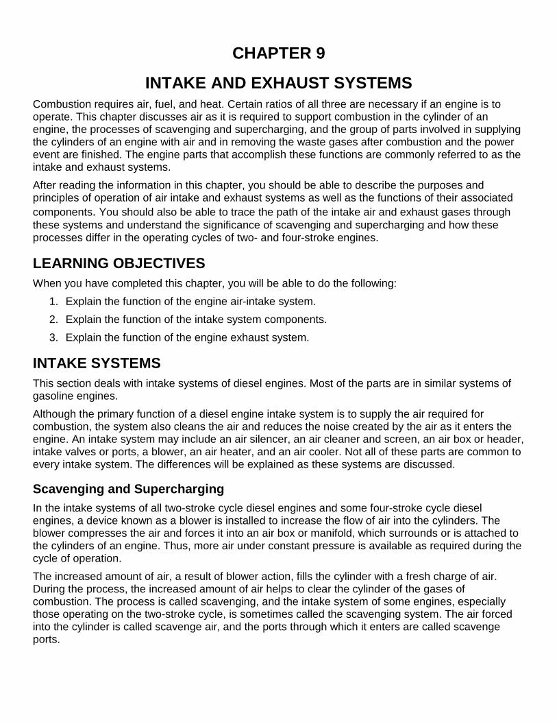
Silencers, Screens, and Cleaners Diesel engines use a great amount of air that enters from the intake system. This air must enter as quietly and clean as possible. Unless a silencer is installed, the air that rushes through the air-cleaning devices will sound like an extremely high-pitched whistle. Consequently, silencers are generally constructed as part of the air-cleaning components. One type of air-intake silencer assembly is shown in Figure 9-4. The silencer assembly is bolted to the intake side of the blower (Figure 9-2). A perforated steel partition divides the silencer lengthwise into two sections. Air enters the end of the silencer and passes through the inner section into the blower. The noise of the air passes through the silencer where it is reduced by a sound-absorbent, flameproof, felted cotton waste, which fills the outer section of the silencer. Upon leaving the silencer, the air enters the blower through an air-intake screen (Figure 9-4). The air-intake screen prevents particles of foreign material from entering the engine. Unless it is filtered from the intake air, foreign material might seriously damage the blower assembly and internal engine parts, such as pistons, piston rings, and liners. The silencer-and-screen assembly just described is sometimes referred to as a dry-type cleaner and silencer. Another type of air cleaner and silencer is the viscous type. In both dry and viscous types, intake air is drawn through a fine mesh or screen, which filters the air. The mesh of such cleaners may consist of cotton fabric, wire screening, specially wound copper crimp, or metal wool. The principal difference between cleaners of the dry and viscous types is that the mesh of a viscous-type cleaner is wet, usually, with a medium-weight oil. An air cleaner and silencer assembly of the viscous type is shown in Figure 9-5. The filter and silencer of this unit form a cylinder silencing chamber, the ends of which are packed with sound-deadening material. Air enters the silencer through the circumferential surface of the silencing chamber. The filter element fits over the air inlet. The element of the filter consists of a series of oil-wetted wire baffles, which collect any airborne dirt entering the chamber.
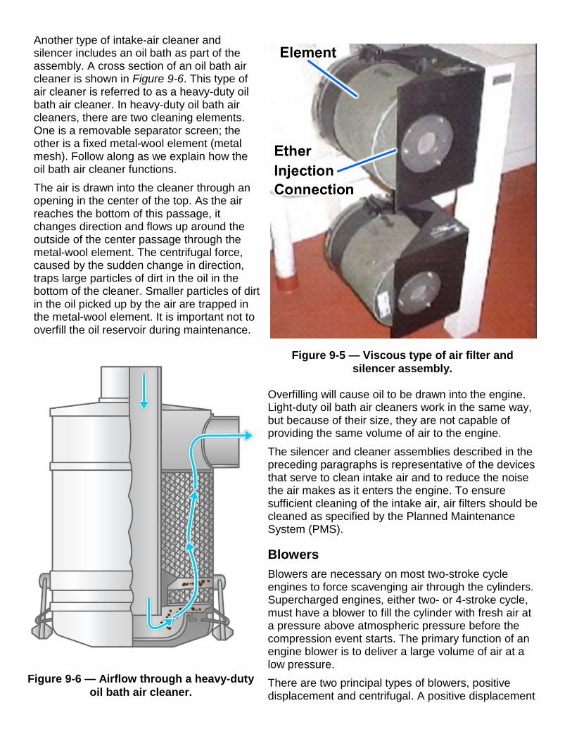
Figure 9-5 — Viscous type of air filter and silencer assembly.
Another type of intake-air cleaner and silencer includes an oil bath as part of the assembly. A cross section of an oil bath air cleaner is shown in Figure 9-6. This type of air cleaner is referred to as a heavy-duty oil bath air cleaner. In heavy-duty oil bath air cleaners, there are two cleaning elements. One is a removable separator screen; the other is a fixed metal-wool element (metal mesh). Follow along as we explain how the oil bath air cleaner functions. The air is drawn into the cleaner through an opening in the center of the top. As the air reaches the bottom of this passage, it changes direction and flows up around the outside of the center passage through the metal-wool element. The centrifugal force, caused by the sudden change in direction, traps large particles of dirt in the oil in the bottom of the cleaner. Smaller particles of dirt in the oil picked up by the air are trapped in the metal-wool element. It is important not to overfill the oil reservoir during maintenance.
Overfilling will cause oil to be drawn into the engine. Light-duty oil bath air cleaners work in the same way, but because of their size, they are not capable of providing the same volume of air to the engine. The silencer and cleaner assemblies described in the preceding paragraphs is representative of the devices that serve to clean intake air and to reduce the noise the air makes as it enters the engine. To ensure sufficient cleaning of the intake air, air filters should be cleaned as specified by the Planned Maintenance System (PMS).
Blowers Blowers are necessary on most two-stroke cycle engines to force scavenging air through the cylinders. Supercharged engines, either two- or 4-stroke cycle, must have a blower to fill the cylinder with fresh air at a pressure above atmospheric pressure before the compression event starts. The primary function of an engine blower is to deliver a large volume of air at a low pressure. There are two principal types of blowers, positive displacement and centrifugal. A positive displacement
Figure 9-6 — Airflow through a heavy-duty oil bath air cleaner.

Figure 9-7 — Roots blower.
blower is usually gear driven directly by the engine, while a centrifugal blower is usually driven by an exhaust-gas turbine. Positive displacement blowers may be divided into two groups: the multiple-lobe type, commonly called the lobe, or roots, blower; and the axial-flow blower. Blowers are introduced briefly in Fireman, NAVEDTRA 14104. The roots blower is commonly used on many two-stroke cycle engines. Exhaust-driven centrifugal blowers (turbocharger) found in many four-stroke engine and some two-stroke engines will be discussed later.
Roots Blower Designed for efficient diesel operation, the roots blower, shown in Figure 9-7, supplies the fresh air needed for combustion and scavenging. The air volume needed for the engine to perform scavenging is about 40 times greater than the cylinder volume. The location of the blower on the engine depends on the cylinder arrangement. Figure 9-8 shows the location of the roots blower on a V-type engine. Figure 9-2, shows the blower location on an in-line engine. The operation of the blower is similar to that of a gear-type pump. Two hollow, three-lobe rotors revolve in opposite directions (Figure 9-8). When the rotors turn, air is drawn in the space between the lobes at the inlet, is trapped, and is carried around to the discharge side. The meshing lobes at the discharge side force the air out of the lobe pockets and into the air box, where the air is then available for use. A continuously uniform supply of air can be maintained. The rotor lobes are made with a helical (spiral) shape (Figure 9-9). In the helical design, one discharge phase begins before the previous discharge phase is entirely completed, and the lobes are said to overlap. This overlapping tends to produce a smoother discharge of air than could be realized if the rotor lobes were of a straight design. Helical timing gears located on the drive end of the rotor shafts prevent the meshing rotor lobes from touching (Figure 9-9). Each rotor is supported in the doweled end plates of the blower housing by a roller bearing at the front end and by a two-row radial and thrust ball bearing at the gear end. Lubrication of the blower bearings, timing gears, and governor drive is provided through oil passages that lead from the main oil galleries of the engine to an oil passage in each end plate of the blower. The rotor lobes require no lubrication because they are prevented from touching by the timing gears.

Figure 9-8 — Air-intake system through a root-type blower on a V-type engine.
Figure 9-9 — Components of a root-type blower.
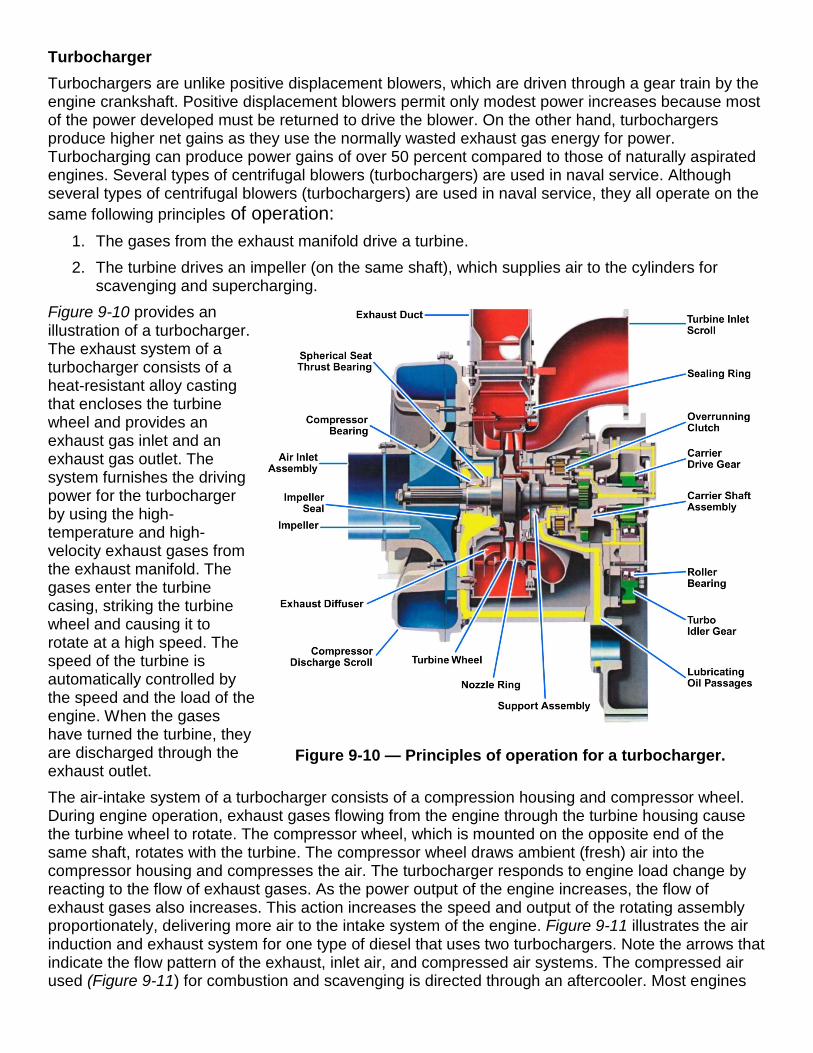
Figure 9-10 — Principles of operation for a turbocharger.
Turbocharger Turbochargers are unlike positive displacement blowers, which are driven through a gear train by the engine crankshaft. Positive displacement blowers permit only modest power increases because most of the power developed must be returned to drive the blower. On the other hand, turbochargers produce higher net gains as they use the normally wasted exhaust gas energy for power. Turbocharging can produce power gains of over 50 percent compared to those of naturally aspirated engines. Several types of centrifugal blowers (turbochargers) are used in naval service. Although several types of centrifugal blowers (turbochargers) are used in naval service, they all operate on the same following principles of operation:
1. The gases from the exhaust manifold drive a turbine. 2. The turbine drives an impeller (on the same shaft), which supplies air to the cylinders for
scavenging and supercharging. Figure 9-10 provides an illustration of a turbocharger. The exhaust system of a turbocharger consists of a heat-resistant alloy casting that encloses the turbine wheel and provides an exhaust gas inlet and an exhaust gas outlet. The system furnishes the driving power for the turbocharger by using the high-temperature and high-velocity exhaust gases from the exhaust manifold. The gases enter the turbine casing, striking the turbine wheel and causing it to rotate at a high speed. The speed of the turbine is automatically controlled by the speed and the load of the engine. When the gases have turned the turbine, they are discharged through the exhaust outlet. The air-intake system of a turbocharger consists of a compression housing and compressor wheel. During engine operation, exhaust gases flowing from the engine through the turbine housing cause the turbine wheel to rotate. The compressor wheel, which is mounted on the opposite end of the same shaft, rotates with the turbine. The compressor wheel draws ambient (fresh) air into the compressor housing and compresses the air. The turbocharger responds to engine load change by reacting to the flow of exhaust gases. As the power output of the engine increases, the flow of exhaust gases also increases. This action increases the speed and output of the rotating assembly proportionately, delivering more air to the intake system of the engine. Figure 9-11 illustrates the air induction and exhaust system for one type of diesel that uses two turbochargers. Note the arrows that indicate the flow pattern of the exhaust, inlet air, and compressed air systems. The compressed air used (Figure 9-11) for combustion and scavenging is directed through an aftercooler. Most engines

Figure 9-11 — Air induction and exhaust system.
Figure 9-12 — Engine air system with roots blower and turbocharger assemblies.
that are turbocharged use aftercoolers to cool the compressed air. Aftercoolers, also referred to as heat exchangers, are small radiators placed between the compressor housing and the intake manifold of the engine. As the compressed hot air passes through the aftercooler, the air is cooled to reduce its volume. Consequently, more air is able to enter the cylinder. The result is lower cylinder pressure, more effective cooling of the cylinder component, and a lower exhaust temperature. Without the aftercooler, the air temperature entering the intake manifold will increase sharply because of the compression of the air and heat from the turbocharger. This undesirable condition can result in a loss of air density and power, a higher temperature within the cylinder, and a higher exhaust gas temperature. In some installations, roots blowers and turbochargers are used together within one system. These two components serve to compress the air more efficiently than would be possible if only a blower or a turbocharger were to be used separately. As we discuss this type of system, refer to Figure 9-12. In operation, air is drawn into the blower section of the turbocharger through the air cleaner. Air is compressed, and the temperature is increased. The high-temperature compressed air is then delivered to the intercooler (heat exchanger), where the temperature is reduced. (Intercoolers are heat exchangers that are usually located between the compressor and the roots blower.) The cooled dense charge of air is then routed to the roots blower inlet. The roots blower further compresses the air and delivers it to the engine.
During the intake event, air is forced into the cylinders where it scavenges (cleans) out the combustion gases and fills the cylinder with a clean, dense air charge that is above atmospheric pressure. After the combustion and power event are completed, the exhaust valves open and the hot exhaust gases are discharged to the exhaust manifold. The hot, high-velocity exhaust gases are directed to the turbine section of the turbochargers, where they drive the turbine wheel at high speed. During this process, the pressure and the temperature of the exhaust gases are reduced and some of the energy that would otherwise be lost is used to drive the turbocharger. After the exhaust gases leave the turbocharger, they are routed to a muffler.
Intake Air Passages Air must pass through a number of passages to reach the combustion spaces within an engine. From the blower or turbocharger, the air is discharged into a unit or passage that is directed to the intake valves or ports of the cylinders. In two-stroke cycle engines, the passages that conduct intake air to the cylinders are generally referred to as an air box. The air box surrounds the cylinders (Figure 9-2) and is built into the block. In two-stroke cycle, V-type diesel engines, the air box consists of the space (within the block) between the two banks of the V-construction and the open space between the upper and lower deckplates of each bank (Figure 9-8). In some two-stroke cycle engines, the passage that serves as a reservoir for intake air from the blower is called an air header. Drains are generally provided in air boxes, receivers, and headers to drain off any liquids that may accumulate. A slight amount of vapor from the air charge may condense and settle in the air box, or a small amount of lubricating oil may be blown into the air box as the piston passes the ports on the downstroke following the power event. On some engines, the drains are vented to the atmosphere. In others, a special drain tank collects the drainage from the air box. The purpose of the tank is to prevent drainage of oil into the engine room. Drains are of primary importance when the air cooler is installed between the blower (or turbocharger) discharge and air-intake manifold or receiver. The drains are usually left open during engine operation to prevent condensation or water from leaky coolers from being carried into the engine cylinders with the combustion air. In four-stroke cycle diesel engines, the intake air passages from the blower to the cylinders differ from those in two-stroke cycle engines in that these passages are not an integral part of the block. Instead, a separate unit is attached to the block to conduct intake air to the engine cylinders. The attached unit is generally called an air-intake manifold.
Cylinder Ports and Valves The amount of air that enters the cylinders from the air box or manifold is controlled by the opening and closing of the cylinder valves or ports. Whether air is admitted to the cylinders of engines through ports or by valves depends upon the type of engine. In four-stroke cycle engines, the amount of air that enters the cylinders is controlled by valves. Ports control the discharge of exhaust gases from some two-stroke cycle engines, and valves perform the same function in all four-stroke and many two-stroke cycle engines. We have made frequent reference in this chapter to ports and have illustrated their location in the cylinder liner. Intake ports (Figures 9-1, 9-2, and 9-8) are usually located in such a way that air enters the cylinder in a whirling motion. The turbulence created helps to increase the amount of intake air that is reached by the injected fuel particles. Thus, the power output of the engine is increased. Intake ports as well as exhaust ports are opened and closed by the piston as it moves back and forth in the cylinder. The valves of an engine are opened and closed at the proper point in the cycle of operation by the valve mechanisms.

Figure 9-13 — Cylinder test and safety valves.
Cylinder Test Valves and Safety or Relief Valves In some large engines, each cylinder is equipped with valves that serve different purposes from those of the intake and exhaust valves. Instead of admitting air to the cylinder or permitting the exhaust gases to escape, these valves may be used for testing or safety purposes. Even though they are not a part of the air system of the engine, these valves are definitely related to the air system because they serve to test or relieve pressure that may develop with the combustion space. Figure 9-13 illustrates a test valve (hand operated):
• To vent the cylinder of any accumulated water or oil before an engine is started.
• To relieve cylinder pressure when the engine is being turned by hand.
• To test compression and firing pressures.
Manufacturers use the terms safety valves and relief valves to identify valves installed in cylinder heads or liners that serve to relieve excessive pressure that may develop when the engine is operating. These valves are of the spring-loaded poppet type. These valves are designed to open when the cylinder pressure exceeds a safe operating limit. A sectional view of the safety valve and test valve arrangement is shown in Figure 9-13. Note the passage and adapter for a cylinder pressure indicator. Most test and relief valve arrangements have an adapter for the cylinder pressure measuring instrument. In Figure 9-13, the valves are fitted in passages within the cylinder head. In some engines, the relief valve is attached separately to the exterior of the head or liner
EXHAUST SYSTEMS The parts of engine air systems considered so far have provided a passage for air into the cylinders and for the release of gases from the cylinders after combustion. The relationship of blowers, or turbochargers, to both the intake and exhaust systems has also been pointed out. The system that functions primarily to carry gases away from the cylinders of an engine is called the exhaust system. An exhaust system may be designed to perform one or more of the following functions: muffle exhaust noise, quench sparks, remove solid material from exhaust gases, and furnish energy to a turbine-driven supercharger. In the following sections, we will discuss the principal parts that may be used in combination to accomplish the functions of an engine exhaust system.
Exhaust Manifolds When the gases of combustion are forced from the cylinders of an engine, the gases enter a unit that is generally referred to as the manifold. The exhaust manifold for a large diesel is shown in Figure 9-14. This exhaust manifold is made up of sections; called chamber assemblies, expansion joints, and adapter assemblies. The expansion joints, which are used between chamber assemblies, provide the necessary flexibility to compensate for expansion and contraction of the manifold resulting from
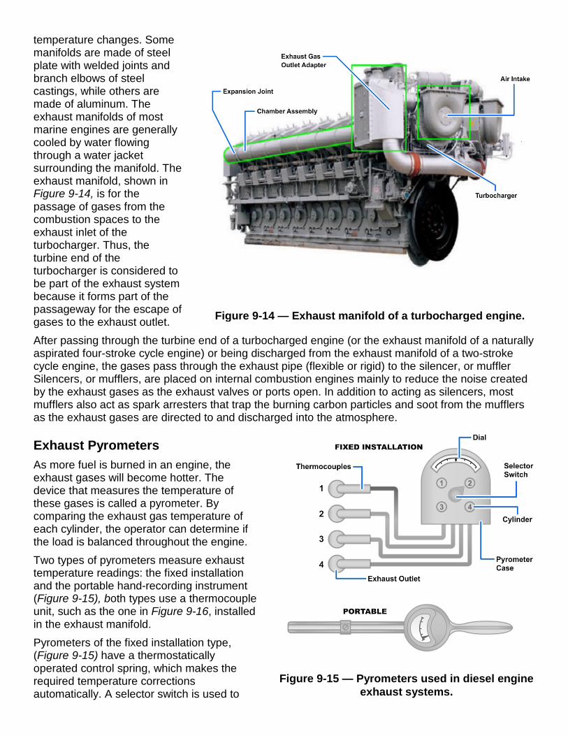
Figure 9-14 — Exhaust manifold of a turbocharged engine.
Figure 9-15 — Pyrometers used in diesel engine exhaust systems.
temperature changes. Some manifolds are made of steel plate with welded joints and branch elbows of steel castings, while others are made of aluminum. The exhaust manifolds of most marine engines are generally cooled by water flowing through a water jacket surrounding the manifold. The exhaust manifold, shown in Figure 9-14, is for the passage of gases from the combustion spaces to the exhaust inlet of the turbocharger. Thus, the turbine end of the turbocharger is considered to be part of the exhaust system because it forms part of the passageway for the escape of gases to the exhaust outlet. After passing through the turbine end of a turbocharged engine (or the exhaust manifold of a naturally aspirated four-stroke cycle engine) or being discharged from the exhaust manifold of a two-stroke cycle engine, the gases pass through the exhaust pipe (flexible or rigid) to the silencer, or muffler Silencers, or mufflers, are placed on internal combustion engines mainly to reduce the noise created by the exhaust gases as the exhaust valves or ports open. In addition to acting as silencers, most mufflers also act as spark arresters that trap the burning carbon particles and soot from the mufflers as the exhaust gases are directed to and discharged into the atmosphere.
Exhaust Pyrometers As more fuel is burned in an engine, the exhaust gases will become hotter. The device that measures the temperature of these gases is called a pyrometer. By comparing the exhaust gas temperature of each cylinder, the operator can determine if the load is balanced throughout the engine. Two types of pyrometers measure exhaust temperature readings: the fixed installation and the portable hand-recording instrument (Figure 9-15), both types use a thermocouple unit, such as the one in Figure 9-16, installed in the exhaust manifold. Pyrometers of the fixed installation type, (Figure 9-15) have a thermostatically operated control spring, which makes the required temperature corrections automatically. A selector switch is used to

Figure 9-16 — Sectional view of a thermocouple.
show the readings of one cylinder at a time. The portable hand pyrometer (Figure 9-15), has a zero adjuster, which must be set by hand and placed in contact temporarily with the terminals of each thermocouple. The indicating unit of the pyrometer is calibrated to give a direct reading of temperature. However, the pyrometer actually measures the difference between the electric current produced by heat acting on dissimilar metals in the thermocouple hot junction and cold junction. The metals most commonly used in the thermocouple are iron and constantin, which are covered by an insulator. The thermocouple is placed so that the hot junction is in contact with the exhaust gases. When the hot junction is heated by the exhaust gases, a small voltage develops in proportion to the temperature. This voltage is transferred by the wires to the pyrometer indicator. The pyrometer indicator is actually a sensitive voltmeter that has a scale that is graduated to show temperatures between the hot junction and the cold junction. Some variations in exhaust temperatures are normal and are to be expected when engines are operating at other than full power. The amount that exhaust temperatures may differ from cylinder to cylinder will depend on the type of engine. Refer to the appropriate manufacturer’s technical manual for the allowable limits for your diesel.
Parts of Other Systems Related to Engine Intake and Exhaust Systems The parts discussed in this chapter are those generally associated with the air systems of most engines. Some engines are equipped with parts that perform special functions. These parts, even though related to the engine air systems, are more frequently considered as parts of other engine systems. Some engines are equipped with intake air heaters or use other methods to overcome the influence of low temperatures in cold weather starting. Many engines are equipped with devices or systems that provide crankcase ventilation. Blower action is necessary in many ventilation systems. The systems operate to prevent contamination of engine-room spaces by heated or fumeladen air to reduce the formation of sludge in lubricating oil and to prevent the accumulation of combustible gases in the crankcase and in the oil pan or sump. Devices that serve to ventilate engine crankcases are discussed with the lubricating systems.
SUMMARY In diesel engines, the passageway for air into the combustion spaces and burnt gases from the combustion spaces is formed by the parts of two systems—the intake and exhaust systems. The combustion spaces serve as the dividing line between these two systems. The primary purpose of an intake system is to supply to the cylinders a large volume of air for combustion and scavenging. The system must clean the air and reduce the noise created by the air as it enters the engine. When the air has served its purpose in the cylinder, the waste gases are expelled to the atmosphere by the exhaust system. In the turbocharged engine, the waste gases serve to drive the turbocharger prior to the expulsion of the gases to the atmosphere by way of the exhaust system.

After studying the information in this chapter, you should understand both the purposes and the principles of operation of the components of the air and exhaust systems in an engine and be able to trace the path of the intake air and exhaust gases through the systems. You should also be able to understand the significance of scavenging and supercharging and how these processes differ in the operating cycles of two- and four-stroke cycle engines. If you are uncertain in any of these areas, go back and review those sections of this chapter before proceeding to the next chapter.

End of Chapter 9
Intake and Exhaust Systems Review Questions 9-1. Which of the following components is part of the diesel engine air-intake system?
A. Muffler B. Air box C. Spark arrester D. Silencer
9-2. What process involves using an increased amount of air to clear the cylinder of combustion
exhaust gases?
A. Natural exhaust B. Turbocharged C. Supercharged D. Scavenging
9-3. Supplying more air to the combustion space than can be supplied from atmospheric pressure
or piston action, on a four-stroke diesel engine, is what process?
A. Supercharged B. Turbocharged C. Natural aspirated D. Scavenging
9-4. Which of the following statements describes the timing difference between a supercharged and
non-supercharged diesel engine compression and power events?
A. Longer in a supercharged engine B. Shorter in a supercharged engine C. No difference D. Compression event longer, and power event shorter on a supercharged engine
9-5. What component is used on a diesel engine air-intake system to ensure the incoming air is as
quiet and clean as possible?
A. Filter B. Cleaner C. Muffler D. Silencer
9-6. What grade of oil is used on the viscous- type air cleaner?
A. Extra-duty weight B. Heavy-duty weight C. Light-duty weight D. Medium-duty weight

9-7. What determines the location of the blower on a diesel engine?
A. Space allotment in the engine room B. Cylinder arrangement C. Placement of gears D. Crankshaft web design
9-8. After the exhaust air leaves the turbocharger but before it enters the air-intake housing, the air
passes through what component to compress its volume?
A. Strainer B. Baffles C. Aftercooler D. Blower
9-9. Most marine engines exhaust manifolds are cooled by what method?
A. Force draft air B. Shell and tube cooler C. Water jacket surrounding manifold D. Installed cooling coils
9-10. What instrument is used to measure exhaust gases?
A. Thermostat B. Gasometer C. Pyrometer D. Thermometer
9-11. What action produces the minimum turbulence and improves the effectiveness of the
scavenging action?
A. Direct line intake B. Cross pattern intake C. Steam line intake D. Uniflow intake
9-12. From what source, if any, do the rotor lobes receive lubrication?
A. Main oil gallery B. Governor drive assembly C. Crankshaft oil passages D. Lubrication not required
RATE TRAINING MANUAL – User Update SWOS makes every effort to keep their manuals up-to-date and free of technical errors. We appreciate your help in this process. If you have an idea for improving this manual, or if you find an error, a typographical mistake, or an inaccuracy in SWOS manuals, please write or e-mail us, using this form or a photocopy. Be sure to include the exact chapter number, topic, detailed description, and correction, if applicable. Your input will be brought to the attention of the Technical Review Committee. Thank you for your assistance. Write: SWOS Project Manager
1534 Piersey Street Suite 321 Norfolk, VA 23511-2613 COMM: (757) 444-5332 DSN: 564-5332
E-mail: Refer to the Engineman Rating page under SWOS on the NKO Web page for current contact information.
Rate____ Course Name_____________________________________________
Revision Date__________ Chapter Number____ Page Number(s)____________
Description
_______________________________________________________________
_______________________________________________________________
_______________________________________________________________
(Optional) Correction
_______________________________________________________________
_______________________________________________________________
_______________________________________________________________
(Optional) Your Name and Address
_______________________________________________________________
_______________________________________________________________
_______________________________________________________________