chapter 9 - nec standards of safety
TRANSCRIPT

C
hapter9NEC Standards
of Safety
Chapter Outline
Conductor Sizing 190
Branch Circuit Sizing 195
AFCI Protection 196
Circuit Rating 197
Feeder Sizing 199
General Use Receptacles 202
Calculating Branch Circuits 203
Feeder and Service Loads 204
General Lighting Loads 204
Additional Service and Feeder Loads 206
Feeder and Service Loads Verses Branch-Circuit Loads 209
Small Appliance and Laundry Loads 210
Electric Clothes Dryer Loads 211
Feeder and Service Load Calculations 211
Service Loads 212
Overcurrent Protection 213
Generators 216
Transformers 218
© 2010 Elsevier Inc. All rights reserved.
Doi: 10.1016/B978-1-85617-654-5.00009-1
189
190 Electrical Safety Code Manual
Clearance Safety 219
ARC Welding 220
As an electrician, you are responsible for the health and safety of
both yourself and the public. Many people think of NEC requirements
as a performance standard, when they actually provide the bare mini-
mum for safe installations. The guidelines are not meant to provide
the most convenient or efficient installations and don’t even guarantee
good service or allow for future expansion. They are designed to pro-
vide a standard for safety that protects against electrical shock and
thermal effects, as well as dangerous overcurrents, fault currents, and
overvoltage.
Conductor sizing
The insulation on a conductor imprisons the dangerous electrical cur-
rent running through it and guards against shock, fire, and arc inci-
dents. For this reason, you must size conductors properly so that
excessive loads do no overheat the conductors and damage the protec-
tive insulation. Article 310 of the NEC deals with the minimum size
requirements for conductors based on their voltage rating as illustrated
in Figure 9.1.
NEC Article 310.15 addresses ampacity, which needs to be cross-
referenced to NEC Table 310.5, because Article 310.15 doesn’t take
voltage drop into consideration. When you run calculations from the
tables, you might come up with more than one ampacity, in which
case you have to use the lower of two or more ampacities. Additionally,
you have to adjust or “derate” your ampacity calculations based on
ambient temperature or more than three current-carrying conductors
in a wireway. The conductor ampacity that you adjusted from the
ambient temperature de-ration calculation has to be multiplied by the
percentage of ampacity de-ration that is required by NEC 310.15(B)(2)a
(Figure 9.2).

CONDUCTOR AND LOAD SUMMARY
· Step 1: Size the overcurrent protection device in accordance with Sections210.20(A), 215.3, and 384.16(D). These three NEC rules require that the breaker or fuse overcurrent protection device be sized at no less than 100% of thenoncontinuous load, plus 125% of the continuous load.
NOTE: Section 240.6(A) contains the list of standard size overcurrent protection devices.
· Step 2: Select the proper conductor size in accordance with Sections 110.4(C),and also NEC 210.19(A), 215.2, and 230.42(A) which required that the conductor be sized no less than 100% of the noncontinuous load, plus 125% of the continuous load. In addition, Section 110.14(C) required you to consider the temperature rating of the equipment terminals when you size the conductors. In order to do this, you need to size the circuit conductors according to the 60°C column of Table 310-16 for equipment that is rated 100 amperes and less. Equipment rated over 100 amperes needs be sized based on the 75°C column of Table 310-16.
· Step 3: Now that you have selected the proper conductors to use, you have toprotect them against overcurrent in accordance with NEC 240.3, which requiresthe branch circuit, feeder, and service conductors be protected in accordance withtheir ampacities as specified in Table 310.16. Remember when you do this, thatsection 240.3(B) allows you to use the next size up if the conductors are not partof a multi-outlet branch circuit that supplies receptacles, and as long as theampacity of the conductors doesn’t correspond with the standard ampere rating of a overcurrent protection fuse or a circuit breaker listed in NEC 240.6(A). Also, the next higher standard rating can not exceed 800 amperes.
Assume you have 19 kVA of nonlinear loads with 75°C terminals, and that the branch-circuit is supplied by a 208/120 volt, 4-wire, 3-phase. Let’s walk through the steps to determine what size branch-circuit overcurrent protection device and conductor (THHN) is required for this installation based on the process we just reviewed.
Step 1: Size the overcurrent protection device in accordance with210.20(A) and 384.16(D). The first thing that you need to do is to convertthe nonlinear load from kVA to amperes:
Amperes = VA/(Volts � 1.732), Amperes = 19,000/(208 volts � 1.732), Amperes = 52.74amperes. Round up 53 amperes
The branch-circuit overcurrent protection device has to be sizedbased on at least 125% of the 53 amperes.
53 amperes � 125% = 66 amperes*
*You need a minimum 70 ampere overcurrent protection device,based on NEC 240.6(A).
Step 2: Select the proper conductor size in accordance with Sections110.4(C), and also NEC 210.19(A), 215.2, and 230.42(A). NEC 210.19(A) also requires that the branch-circuit conductor be sized no less than 125% of the continuous load.
Figure 9.1—Cont’d
NEC Standards of Safety 191

53 amperes � 125% = 66 amperes
You need to pick the conductor based on the 75°C terminals temperaturerating of the equipment terminals. No. 6 THHN has a rating of 65 amperesat 75°C, so you can not use that size. You need to go to the next size up.
Use #4 THHN which has a rating of 85 amperes at 75°C.
Step 3: Protect the #4 THHN conductor against overcurrent inaccordance with NEC 240.3. First, you need to confirm that the #4 THHNis properly protected against overcurrent by the 70 ampere overcurrent protection device listed. To do this, you need to look at the fact that you have a 4-wire, 3-phase service. Since that are more than three current-carrying conductors in the same raceway, you have to adjust the #4 THHN conductor ampacity to the amperage listed in the 90°C column of NEC Table 310.16.
Corrected Ampacity for #4 THHN = Ampacity � Note 8(A). The Adjustment Factor Corrected Ampacity of #4 THHN = 95 amperes � 80%.
Corrected Ampacity #4 THHN = 76 amperes
For the #4THHN that is rated at 76 amperes after ampacityfactors, the proper overcurrent protection device will need to berated at 70 amps in order to comply with the general requirementsof NEC 240.3.
Let’s work through another example using a 184 amp feeder continuous load on a panelboard with 75°C terminals that supplies nonlinear loads. We will assume that the feeder is supplied by a 4-wire, 3-phase, wye connected system and determine what size feeder overcurrent protection device and THHN conductor are required to meet code standards.
· Step 1: Size the overcurrent protection device in accordance with NEC 215.3 and384-16(D). The feeder overcurrent protection device be sized at least 125% of the184 amperes.
184 amperes � 125% = 230 amperes.
NOTE: According to NEC 240.6(A) you must use a minimum 250 ampereovercurrent protection device.
· Step 2: Select the conductor that will comply with NEC 110.14(C) and withNEC 215.2 which requires the feeder conductor to be sized no less than 125% of the continuous load.
184 amperes � 125% = 230 amperes. You then need to select a conductoraccording to the 75°C temperature rating of the panelboards terminals.
#4/0 THHN has a rating of 230 amperes at 75°C.
· Step 3: Protect the #4/0 conductor against overcurrent based on the requirementsin NEC 240.3. Start by verifying that the #4/0 THHN conductor would beadequately protected by a 250 amp overcurrent protection device. Since our
Figure 9.1—Cont’d
192 Electrical Safety Code Manual

sample installation is a 4-wire, 3-phase, wye connected system, you know youwill have more than three current-carrying conductors in the same raceway, soyou have to correct the #4/0 THHN conductor ampacity by the 90°C column ofNEC Table 310-16.
Corrected Ampacity for #4/0 THHN = Ampacity � Note 8(A). The AdjustmentFactor Corrected Ampacity for #4/0 THHN = 260 amperes � 80%
Corrected Ampacity for #4/0 THHN = 208 amperes
The #4/0 THHN that is rated at 208 amps after you applied the ampacitycorrection would not be properly protected by a 250 amp overcurrent protectiondevice, because “the next size up rule” in NEC 240.3(B) would only permit a 225amp OCPD on your 208 amp conductor. This means you have to increase theconductor size to 250 kcmil in order to comply with the overcurrent protectionrules of NEC 240.3
Figure 9.1—Cont’d Minimum conductor sizes permitted in NEC 310.5.
Number of Current-Carrying Conductors
Values in NEC Tables 310.16 - 310.19 Adjusted for Ambient Temperature,
if Necessary
4-6 80 %7-9 70 %
10-20 50 %21-30 45 %31-40 40 %
40 and above 35 %
Figure 9.2 Adjustment factors are required for more than three current-carrying con-ductors in a raceway or cable.
NEC Standards of Safety 193
Here is an example of applying these requirements:
n Assume you plan on running a #8 AWG TW copper conductor in
an attic that has an approximate average ambient temperature of
130�F. There will be a total of 26 current-carrying conductors in the
conduit.
n STEP 1: Begin by looking at NEC Table 310.16 in the first
column (for 60 �C/140�F). You will see that #8 copper TW is rated
at 40 A.
194 Electrical Safety Code Manual
n STEP 2: In order to determine what correction factor to use, you
will need to convert 130�F to centigrade. The formula for this is:
C ¼ (F�32) � 9 � 5.
So using this formula, your conversion would work like this:
130� 32 ¼ 98 98� 9 ¼ 10.888 10.9� 5 ¼ 54:5
n STEP 3: Locate 55 �C in the ambient temperature column of the
correction factors section of Table 310.16. You will see that the
corresponding correction factor is 0.41.
n STEP 4: Multiply the 40 A from Step 1 by the 41% correction factor
in Step 3, which will give you a total of 16.4. This means you have
16.4 A of ampacity after the temperature de-ration calculation.
n STEP 5: Next, you need to turn back to NEC Table 310.15 (B)(2)
and locate the number of current-carrying conductors in your race-
way, which we listed in the essential installation information as 26
conductors, and find the adjustment value for ambient temperature
that correlates to the quantity of conductors. For between 21 and
30 conductors, you will use the value of 45%.
n STEP 6: Next, take the amps you calculated in Step 4 of 16.4 and
multiply that times the 45% value you came up with in Step 6:
16.4 � 0.45 ¼ 7.38. This means that 7.38 is the total reduction of
ampacity after the ambient temperature de-ration and de-ration for
the quantity of conductors are factored in. Round this amperage
DOWN and you have 7 A as the true adjusted total ampacity rating
of the #8 AWG TS copper conductor.
n STEP 7: The NEC requires you to have a minimum ampacity of 15
A for any conductor that is used in a wiring system of 120 V or more
(NEC Table 210.3). Furthermore, the conductor must have an
ampacity that is no less than the maximum load to be served, based
on the requirements of NEC 210.19(A)1.
You just ran all of these calculations only to find that the #8 AWG TW
conductor you planned to use in this installation is not permitted for
this use. Not only is it not rated at the minimum required 15 A, but
because it is smaller than 15 A it is too small to carry the 120-volt ser-
vice load.

NEC Standards of Safety 195
Branch circuit sizing
Branch circuits are the section of a wiring circuit between the final set of
fuses or final breaker and the outlets it supplies. Dwelling units require
branch circuits with voltages that do not exceed 120 V nominal, and if
the circuits are for luminaires or cord-and-plug connected loads don’t
exceed 1440 V A, or less than ¼ horsepower (Figure 9.3).
NEC Article 210.11 provides the number of branch circuits permitted
in any given system and explains that a load that is computed on a
VA/area basis has to be evenly proportioned. A wiring system, includ-
ing the branch circuit panelboard, has to be proportioned to serve the
calculated loads and can never exceed the maximums which are speci-
fied in NEC 220. Loads must also be evenly proportioned and
distributed among the multi-outlet branch circuits with a panelboard.
Branch circuit overcurrent protection devices (OCPD) and circuits only
have to be installed to serve connected loads. Branch circuit OCPD
must have an ampacity of no less than 125% of the continuous loads,
plus 100% of the noncontinuous loads.
There are three categories of branch circuit requirements in NEC 210
for dwelling units. The first is the small appliance branch circuit regula-
tion that requires two or more 20-amp small appliance branch circuit
outlets. The next is laundry branch circuits, which must have one
Coiled white wireconnection to
Load Center neutral
Arc-FaultCircuit
BreakerNeutral
wire(white)
Hot (load)Power Wire
(black)
120v DuplexReceptacle
Figure 9.3 A single-pole branch circuit wiring example.

Figure 9.4 Small-appliance and laundry circuits must be included in load calculations.
196 Electrical Safety Code Manual
20-amp branch circuit that does not supply any other outlets and
supplies just a laundry receptacle. The third requirement is that there
must be a 20-amp branch circuit in any bathroom and that the circuit
does not supply any other receptacle (Figure 9.4).
AFCI PROTECTION
Arc-fault circuit interrupter protection is outlined in NEC 210.12. You
need to understand that AFCI is not the same as GFCI, even though
there are combination units available. The function of an AFCI, which
operates at 30 mA, is to protect equipment while a GFCI, which operates
at between 4 and 6 mA, is designed to protect people. An AFCI provides
protection against the effects of arc faults because it identifies the unique
characteristics of arcing and will de-energize a circuit when an arc fault is
detected. Any of the 15 or 20 A, 120 V, single-phase branch circuits in a
dwelling unit bedroom must have AFCI protection. The 2008 edition of
the NEC allows the AFCI device to be located any distance from the
panelboard, so long as required wiring methods are used to protect the
AFCI device against physical damage. Additionally, the code requires
that all 15 and 20 A branch circuits installed in dwelling units have
arc-fault circuit interrupter protection (Figure 9.5).
The new clarification in the 2008 NEC 210.12 spells out locations that
require AFCI-protection requirements for branch circuits that supply
outlets in dwelling unit family rooms, dining rooms, living rooms, par-
lors, libraries, dens, bedrooms, sunrooms, recreation rooms, closets,

1-Pole Circuit Breakerwith AFCI
Hot (black) wireDuplex Receptacle
120
Neutral
PanelNeutral
(white) wire
Equipment GroundingConductor
Ground
Figure 9.5 An AFCI wiring diagram.
NEC Standards of Safety 197
hallways, or similar areas. However, it is important to note that this
120-volt circuit limitation means AFCI protection isn’t required for
equipment such as baseboard heaters or room air conditioners that
are rated at 230 V.
NEC 210.12. Arc-Fault Circuit-Interrupter Protection states that anAFCI provides “protection from the effects of arc faults by recognizingcharacteristics unique to arcing and by functioning to de-energize the cir-cuit when an arc fault is detected.” It is not a GFCI, though combinationunits do exist. The purpose of an AFCI (30 mA) is to protect equipment.The purpose of a GFCI (4-6 mA) is to protect people.
CIRCUIT RATING
NEC 210.19 provides the rules for minimum amperages and sizes of
conductors. One of the key points that you need to be sure you under-
stand is that before you apply any adjustments or correction factors,
branch conductors must have an allowable amperage that is not lower
than the noncontinuous load of the circuit plus 125% of the continuous
load. Table 210.21(B)(2) illustrates that the maximum load on any
given circuit is 80% of the receptacle rating and circuit rating. You
might find it easiest to read the table from right to left because then
you will be identifying the load you need to supply first and the circuit
rating you need to provide afterwards. Looking at the table in this way,
you can see that if you need to supply a 20-amp load, you need to

Maximum Load In Amps
Receptacle Rating In Amps
Circuit Rating In Amps
12 15 15 or 20 16 20 2024 30 30
Maximum Cord-and-Plug Connected Load to a Receptacle
Figure 9.6 Maximum loads by circuit rating.
198 Electrical Safety Code Manual
install at least a 30-amp receptacle on a 30-amp circuit. An example of
the table information is listed in Figure 9.6.
The next rating table in NEC 210.21(B)(3) lists the various sizes of cir-
cuits connected to a receptacle. Receptacle ratings for branch circuits that
supply two or more receptacles have to fall within the values shown in
the table. If the receptacle rating is more than 50 A, then the receptacle
cannot be rated less than half of the branch circuit rating (Figure 9.7).
The total rating of utilization equipment fastened in place, with the
exception of light fixtures, cannot exceed 50% of the branch-circuit
amperage rating when lighting units, cord-and-plug connected equip-
ment that isn’t fastened in place, or both of these are also supplied.
The safety rationale behind this is to prevent a circuit overload when
an additional load is added, for example if someone plugs in a vacuum
cleaner. The solution is to separate circuits by putting lights on one cir-
cuit, dedicated loads (fastened in place) on different circuits, and conve-
nience receptacles on separate circuits.
Place lights on separate circuits, dedicated (fastened in place) loads onseparate circuits, and convenience receptacles on separate circuits.
Receptacle Rating In Amps
Circuit Rating In Amps
15 15 or 20
20 20
30 30
Receptacle Ratings for Associated Circuit Sizes
Figure 9.7 Receptacles for branch circuits.

NEC Standards of Safety 199
Cord-and-plug connected equipment that is not fastened in place, such
as a table saw for example, cannot have an amperage rating that is
more than 80% of the branch-circuit rating. Portable equipment, like
a hair dryer, may have a UL listing up to 100% of the circuit rating,
but you have to remember that the NEC is an installation standard,
not a product standard. As an electrician, you have no way of knowing
if a circuit will be used at 80% of the branch-circuit rating, but you
must install to that standard.
To keep things simple when you are sizing conductors for branch cir-
cuits, remember that the OCPD defines the circuit. If a 20-amp circuit
contains 8 AWG conductors because of voltage drop, it is still a 20 A
circuit. The rating of the branch circuit is determined by the size of
the OCPD. An individual receptacle on a single branch circuit cannot
have an amperage that is less than the rating of the OCPD, as specified
in NEC Article 210.21(B)(1). Also remember that a single receptacle has
only one contact device on its yoke as described in Article 100, which
means that you would treat a duplex receptacle as two receptacles.
Everything you need to know on a regular basis about branch circuitrequirements is summarized in NEC Table 210.24. Simply look for the cir-cuit rating, which is based on the load you need to supply, and the tableindicates the minimum conductor and tap sizes, overcurrent protection,and maximum load. It also lists which lamp holders are permitted andthe required receptacle rating.
Feeder sizing
The definition of a feeder is the circuit conductors that supply power to
a branch-circuit overcurrent device or to a panel that contains the
OCPD. The power can come from the service equipment, a separately
derived system, or other power supply source. So, what is the main dif-
ference between a branch circuit and a feeder? A feeder runs between an
OCPD at the supply and a downstream OCPD typically supplying a
branch circuit. On the other hand, a branch circuit runs between the
OCPD and an outlet, which is considered the final load. In other words,
a feeder supplies power to a branch-circuit OCPD and that OCPD, in
200 Electrical Safety Code Manual
turn, powers the branch circuit. You need to remember that you don’t
size that branch circuit OCPD based on feeder calculations, but rather
on the branch-circuit load calculations and receptacle outlet require-
ments. NEC Article 215 is fairly short because it only outlines the rules
for installation, minimum size, and ampacity of feeders.
If your computations result in a fraction of an ampere that is less than 0.5,you are permitted to drop the fraction. This is because you are just calcu-lating here, not selecting components, which are available only in stan-dard sizes. The various safety factors in the code already account forenough headroom that dropping a fraction of an amp won’t matter.
When you calculate feeder-circuit conductor loads, the minimum size,
before any adjustments or correction factors are applied, needs to be
no less than the non-continuous load plus 125% of the continuous load.
If the feeder conductors carry the total load supplied by service conduc-
tors that are 55 A or less, then the feeder conductor amperage cannot
be less than the service conductor amperage. To size feeders that supply
transformers, you need to add the transformer nameplate ratings
together and make sure that the feeder conductor amperage is not less
than that sum.
THINK BACKWARDS AND FORWARDS: As you run calculationsas they are laid out in NEC Article 220, keep in mind that these are usedin conjunction with provisions from other articles. Results from calcula-tions in Parts III, IV, and V of Article 220, for example, are used withthe provision in 215.2(A)(1) to find the minimum feeder-circuit conductorsize. The calculations in NEC 220 are also necessary in determiningthe minimum fuse or breaker size allowed for feeders as required byNEC 215.3.
To protect feeder circuits, you must install overcurrent protection. If a
feeder supplies a continuous load, or a combination of continuous and
non-continuous loads, then the OCPD cannot be rated any less than the
non-continuous load plus 125% of the continuous load amperage. Both
of the rating requirements have an exception for assemblies that are
listed to operate at 100% of their ratings, including the OCPD. In these
cases, the ratings can be equal to the sum of the continuous and non-
continuous loads.

NEC Standards of Safety 201
A common neutral is permissible for two sets of four-wire or five-wire fee-
ders, as well as for two or three sets of three-wire feeders. Grounding is
required for all feeders that supply branch circuits that require equipment
grounding conductors. You can tap two-wire DC circuits or AC circuits
with two or more ungrounded conductors. In this situation you would
tap from the ungrounded conductors of the circuits that have a grounded
neutral conductor and use switching devices in each tapped circuit that
have a pole in each ungrounded conductor. The grounded conductor of
a feeder circuit must follow the same standards of identification as any
grounded conductor, which means it must have a continuous white or
gray outer insulated covering or three continuous white stripes on an insu-
lated covering that is not green. Equipment grounding conductors need to
be identified in accordance with NEC 250.119.
NFPA 70E also addresses current-carrying conductors, buses, switches,and disconnects, and requires that they be maintained to conduct ratedcurrent without overheating and to withstand available fault current.
One of the most important aspects of planning a safe electrical installa-
tion is running accurate load calculations. There are a couple of things
to keep in mind when you are running these computations. First of
all, load calculations are affected by demand factors, which is the
ratio of the maximum demand of a system to the total connected load
of that system. While different loads have different demand factors,
the demand factor is always equal to or less than one. Safe and com-
pliant installations depend of your ability to achieve accurate calcula-
tion results. Let’s walk through the process, beginning with common
receptacles.
The computed load of a feeder or service cannot be less than the sum of
computed loads on the branch circuits. You do not select the feeder or
service breakers based on the sum of the branch breaker ratings. You
select them based on the total load supplied by that feeder or service.
That total load must account for demand factors and diversity factors
(for example, you don’t run your air conditioner and heater at the same
time, and you wouldn’t be using all 19 welding receptacles in a small
shop at one time) and other items detailed elsewhere in Article 220.
NEC Table 220.11 lists the demand factors for lighting loads in various

202 Electrical Safety Code Manual
types of occupancies. This is not the reference you use to determine the
quantity of branch circuits for general illumination.
GENERAL USE RECEPTACLES
All general-use receptacle outlets that are rated at either 15 or 20 A
installed in dwellings are included as a part of the general lighting-load
calculations. Let’s look at an example. Assuming that a living room in
a single-family home is 13 feet � 15 feet, first you have to space the
receptacle installation in accordance with NEC 210.52 (Figure 9.8).
Because of the room’s dimensions, nine receptacle outlets are required.
Unlike receptacles for non-dwelling installations that must be calcu-
lated at 180 V A each, dwelling receptacles do not require any addi-
tional load. The general lighting load for this room would need to be
calculated in accordance with 220.12 and Table 220.12, which would
be 3 V A per square foot. For a 13 feet � 15 feet living room, this
equates to 195 square feet times 3 V A, for a total 585 Units. The next
step in the calculation process is not spelled out in the code article.
Based on a normal residential service size of 120/240 V, you need to
complete the calculation by dividing the unit total by 120 (V). This
results in 4.875 (585/120 ¼ 4.875), which should be rounded up to 5.
6�
15�
15�
5�
5�
13�
6�
3�
3� 6� 6�
1�
2�
3�
6�
3�6�2� 6�
4�
6�
2�
4�
6�
Figure 9.8 Living room receptacle requirements.

NEC Standards of Safety 203
The load calculation formula does not change when the number of recep-tacle outlets, specified in 220.14(J)(1) through (J)(3), is more than therequired minimum.
Load calculation does not vary, even if you add more outlets for a
space than are required by the standard. Going back to our 13 feet �15 feet living room example, if you added twice as many receptacles,
the load for space would be calculated exactly the same as in our
example: 195 square feet � 3 ¼ 585/120 ¼ 4.875, which still rounds
up to 5.
CALCULATING BRANCH CIRCUITS
To determine the minimum number of 15-amp and 20-amp branch cir-
cuits needed in dwellings for lighting and general-use outlets, you need
to start with the floor area again. Begin by determining the square foot-
age of the space and then, using Table 220.12, find the general lighting
load required. The resulting lighting load is in amps, which needs to
be divided by either 15 or 20 A for the branch circuits. Let’s look at a
new example. Assume you have a single-family home with outside
dimensions of 50 feet by 30 feet.
n STEP 1: Determine the square footage of the dwelling by multiply-
ing the length time the width: 50 feet � 30 feet ¼ 1500 square feet.
n STEP 2: Calculate the general light load using Table 220.12, which
indicates that the unit load for a dwelling unit is 3 V A per square
foot. So, you would multiply 1500 sq ft � 3 ¼ 4500 V A.
n STEP 3: Confirm that the dwelling voltage is 120/240 V and divide
the minimum light load that you calculated in Step 2 by 120 V: 4500/
120 ¼ 37.5 which should be rounded up to 38.
n STEP 4: Now, to determine the minimum number of 15-amp, two-
wire circuits that are required by the code, you need to divide the
load you determined in Step 3 by 15 A. This comes out to 38 divided
by 15 which equals 2533, which needs to be rounded up to 3. Now
you have determined that at least three 15 A, two-wire circuits are
required for your 50 feet � 30 feet dwelling installation.

204 Electrical Safety Code Manual
To calculate the minimum number of 20-amp general-purpose branch
circuits, you use 20 as your factor in Step 14 instead of 15. So the
calculation process ends up looking like this:
n 50 feet � 30 feet ¼ 1500 sq feet
n 1500 sq feet � 3 ¼ 4500 V A
n 4500/120 ¼ 37.5 (round up to 38)
n 38 divided by 20 ¼ 1.9 which needs to be rounded up to 2
So, based on our sample, the minimum number of 20-amp, two-wire
branch circuits required for our dwelling is two. But wait, there’s more.
You need to have at least one 20-amp laundry circuit and a minimum of
two 20-amp small appliance branch circuits to meet code requirements,
even though your minimum load calculation resulted in only two. Think
about any other associated code requirements that you may need to
consider. For example, bathroom branch circuits that supply receptacle
outlets also must be rated at 20 A. However, no additional load calcula-
tion is required for the bathroom circuits, so you still only need three.
Feeder and service loads
Understanding how to perform load calculations is an important
part of an electrician’s professional career and critical for hazard-free
installations. Feeder and service load calculations include demand
factors that should be applied to some of the branch-circuit load calcu-
lations that you have already run. NEC Annex D is made up of numer-
ous examples intended to explain how to calculate loads based on
actual examples of various conditions such as multifamily dwellings
and industrial feeders in a common raceway.
GENERAL LIGHTING LOADS
You can actually lower the calculated lighting load of a feeder or ser-
vice by utilizing the lighting load demand factors for certain occupancy
types. NEC Table 220.42 lists the demand factors that apply to the por-
tion of the total branch circuit load calculated for general lighting (illu-
mination). Four types of occupancy lighting load conditions are

NEC Standards of Safety 205
provided: single-family and multifamily dwelling units, hospitals, hotels
and motels, and storage warehouses. The hotel and motel standard
includes apartment or rooming houses that do not have provisions for
cooking by the tenants.
General lighting loads are based on the square footage (or square meter)of the occupancy space and the calculation factors only vary based on thetype of occupancy.
Let’s look at a single-family home with a calculated floor area of 4000
square feet as an example of how to apply these demand factors. The
portion of the lighting load that is calculated at 100% is first 3000 V
A or less. The demand factor is 35% for the portion of the lighting load
that ranges between 3001 and 120,000 V A. Next, we have to go
through the process of calculating the comprehensive general lighting
load by using all of the code requirements and this table to apply
demand factors for our 4000 square foot home.
n STEP 1: Since you know the total floor area, begin by multiplying the
square footage of 4000 by the 3 V A per square foot required in NEC
Table 220.12: 4000� 3¼ 12,000. This is the base general lighting load.
n STEP 2: Next, we need to add the minimum of a single laundry cir-
cuit and two small appliance circuits that we know are required for a
single-family dwelling—this was discussed in the section on NEC
210.11 in the previous chapter. Now that we have looked backwards,
we have to read ahead to the circuit load requirements in NEC
220.52. Here we see that we must use 1500 V A for each two-wire,
small appliance branch circuit. So we multiply 1500 � 2 ¼ 3000.
n STEP 3: NEC 220.52(B) requires that we multiply each laundry
branch circuit by 1500 V A also, so we need to include another
1500 V A to our calculation.
n STEP 4: At this point, let’s add together what we have so far:
n 12,000 (from Step 1) þ 3000 (from Step 2) þ 1500 (from Step 3) ¼
16,500n STEP 5: Use this total of 16,500 as your base to run the demand
factors. The first 3000 is a straight 100% which is simply 3000 V A.

206 Electrical Safety Code Manual
The remaining 13,500 (16,500-3000 ¼ 13,500) is subject to the 35%
demand: 13,500 � 35% ¼ 4725.
n STEP 6: This means that the general lighting load for this one-family
dwelling ends up being: 3000 (from Step 1)þ 4725 (Step 5)¼ 7725VA.
Now you have determined the most basic general lighting load for the
house. However, there are additional electrical load elements that can
affect service, circuit, and feeder sizing for any installation.
ADDITIONAL SERVICE AND FEEDER LOADS
Any fixed electric space heater loads are calculated at 100% of the total
connected load. Under no circumstances can the feeder or service load
current ratings be less than the largest supplied branch circuit rating.
Whereas motor and motor-compressor loads must be calculated at
125%, fixed electric space heating loads are simply based on 100%,
but 100% of what exactly?
Assume you are reviewing plans for a small office and the specifications
call for seven wall heaters. Each heater has a rating of 3000 W at 240 V
(Figure 9.9).
Wall Heater3,000 watts240 volts
Figure 9.9 Office heater loads must be based on the total current draw of all the heaters.

NEC Standards of Safety 207
How much load will these heaters add to a 240-volt, single-phase ser-
vice? If you just take NEC 220.51 on face value, then you would calcu-
late the heaters at 100% (7 � 3000 ¼ 21,000 W) and call your formula
done. However, we also need to determine the total current draw of the
heaters. To do this, divide the total watts you just calculated by the 240 V:
n 21,000 � 240 ¼ 87.5 Remember to round-up to 88 A
The calculated load for these seven 3000-watt, 240-volt heaters on a
240-volt, single-phase service is 88 A.
This process is fine if you just have standard heating only units. But
what if you are installing a heating and cooling combination unit?
Heating units that are equipped with blower motors must be calculated
in accordance with NEC 220.50 and 220.51. To do this, let’s assume we
are going to install a heating/cooling package unit in a single-family
dwelling. The specs for the unit indicate that the electric heater is rated
9.6 kW and 240 V and the blower motor inside the package unit is a ½
horsepower, 240-volt motor. Your job is to find out how much of a
load this combination unit adds to the home’s 240-volt, single-phase
service. Follow the steps in the process below:
n STEP 1: Convert the 9.6 kW from kilowatts to basic watts. This is
from your basic electrical math that you had to learn before you
could get your electrician’s license. 9.6 � 1000 (kilo) ¼ 9600 W.
Since the load needs to be eventually determined in amps, you will
need to convert the watts to amps. Using Ohm’s Law, this is done
by dividing the watts by the amps: 9600 � 240 ¼ 40 A (Figure 9.10).
n STEP 2: Next, you need to determine the full-load current in
Fig
amperes of the ½ horsepower, single-phase, 240-volt motor. The
information on how to do this is located in NEC article 430
AMPS OHMS
VOLTS
ure 9.10 Ohms Law diagram.
208 Electrical Safety Code Manual
that focuses on motors, motor circuits, and controllers. NEC
Table 430.248 is a simple chart that lists the horsepower of A/C
motors running at full-load currents and usual speeds with normal
torque characteristics. In other words, the table is geared toward
generic, average conditions. The motor we are using in our example
is rated at 240 V, but when you look at Table 430.248, you may get a
little confused because there is no column for motors rated at 240 V.
Just read the description of the table and you will see that the cur-
rents listed can be used for 110-120 V and 220-240 V (Figure 9.11).
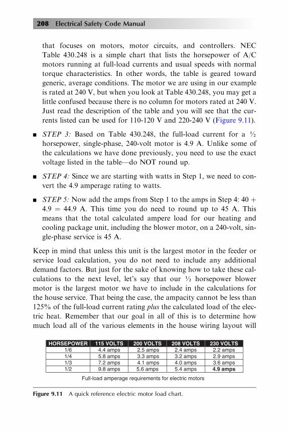
n STEP 3: Based on Table 430.248, the full-load current for a ½
horsepower, single-phase, 240-volt motor is 4.9 A. Unlike some of
the calculations we have done previously, you need to use the exact
voltage listed in the table—do NOT round up.
n STEP 4: Since we are starting with watts in Step 1, we need to con-
vert the 4.9 amperage rating to watts.
n STEP 5: Now add the amps from Step 1 to the amps in Step 4: 40 þ
4.9 ¼ 44.9 A. This time you do need to round up to 45 A. Thismeans that the total calculated ampere load for our heating and
cooling package unit, including the blower motor, on a 240-volt, sin-
gle-phase service is 45 A.
Keep in mind that unless this unit is the largest motor in the feeder or
service load calculation, you do not need to include any additional
demand factors. But just for the sake of knowing how to take these cal-
culations to the next level, let’s say that our ½ horsepower blower
motor is the largest motor we have to include in the calculations for
the house service. That being the case, the ampacity cannot be less than
125% of the full-load current rating plus the calculated load of the elec-
tric heat. Remember that our goal in all of this is to determine how
much load all of the various elements in the house wiring layout will
HORSEPOWER 115 VOLTS 200 VOLTS 208 VOLTS 230 VOLTS 1/6 4.4 amps 2.5 amps 2.4 amps 2.2 amps 1/4 5.8 amps 3.3 amps 3.2 amps 2.9 amps 1/3 7.2 amps 4.1 amps 4.0 amps 3.6 amps 1/2 9.8 amps 5.6 amps 5.4 amps 4.9 amps
Full-load amperage requirements for electric motors
Figure 9.11 A quick reference electric motor load chart.

NEC Standards of Safety 209
add to the dwelling’s service requirements. To determine how much
load this package unit will add to our 240-volt, single-phase service,
we need to multiply the motor’s full-load current by 125% before add-
ing it to the electric heat: 4.9 (from Table 430.248, Step 4 above) �125% ¼ 6.125. Next we have to add in the amps we calculated in Step
1 above of 40 A to arrive at our total amperage: 40 þ 6.125 ¼ 46 A.
You can see the difference in the calculated load when the blower
motor is the largest motor in the service load calculation. It has gone
from 45 to 46 A. This 1 A change can be the difference in a service load
that is code compliant and one that is not.
FEEDER AND SERVICE LOADS VERSES BRANCH-CIRCUIT LOADS
Although fixed electric space heating loads are calculated in accordance
with NEC 220.51 to determine the appropriate feeder and service loads,
branch-circuit loads must be calculated in accordance with NEC article
424. By looking at NEC Table 220.3, we know that we have to specifi-
cally go to Section 424.3 to find “Fixed Electric Space Heater Equip-
ment, Branch-Circuit Sizing.” As previously discussed, branch-circuit
conductors must have an ampacity that is not less than 125% of the
continuous load. If we use our heating and cooling package unit as
an example again, how would we now establish that the minimum size
75 �C branch-circuit conductors are required for the unit?
n STEP 1: The service load for this unit was calculated at 100%, but
in accordance with NEC 430.22(A), the blower motor also had to
be calculated at 125%. We went through this process and came up
with a combined blower motor and heating element current of 44.9
A. Now we have to multiply that amperage by 125%: 44.9 �125% ¼ 56.125 Round this DOWN to 56 A.
n STEP2:Wehave now established that the 75 �Cbranch-circuit conduc-
tors needed for our heating/cooling package unit must be at least 56 A.
n STEP 3: If you wanted to find out the minimum size 75 �C conduc-
tors that would be required to feed this heating/cooling package unit,
you would need to look in Annex B, Table B310.3 in the back of the
code book. Here you will see that for 50 A at 75 �C you can use
8 AWG, but since we need 56 A, we have to jump up to the next level
which is 6 AWG copper conductors for use between 51 and 68 A.

210 Electrical Safety Code Manual
No additional calculations are necessary as long as the heating and
cooling unit provides minimum circuit ampacity and maximum
branch-circuit overcurrent protection that is shown on the nameplate.
If our heating and cooling package unit was listed for a minimum/
maximum fuse or HACR-type breaker of 100 A on the nameplate then
the branch-circuit load would have to be protected by a 100-ampere
fuse or HACR-type circuit breaker.
SMALL APPLIANCE AND LAUNDRY LOADS
Small-appliance branch-circuit loads must be included in the load cal-
culations in order to determine the approved feeder and service loads
for dwelling units. We included them already when we were calculating
our comprehensive general lighting loads. NEC 220.52 requires 1500
V A for each two-wire small-appliance branch circuit. Two or more
20-ampere small-appliance branch circuits required by NEC 210.11(C)
(1) have to serve all wall and floor receptacle outlets, as well as all of
the countertop outlets and all of the receptacle outlets for refrigeration
equipment.
If the load is subdivided through two or more feeders, the calculated
load for each cannot be less than the 1500 V A for each two-wire
small-appliance branch circuit. For example, let’s say that a one-family
dwelling will have three panelboards, not counting the service equip-
ment. One of the panelboards is going to supply three small-appliance
branch circuits and the other two panelboards will not supply any
small-appliance branch circuits. We have to multiply the three small
appliance branch circuits by the required 1500 A: 3 � 1500 ¼ 4500. This
means that 4500 A must be included when we calculate the load for the
panelboard with the three small-appliance branch circuits. But, since
the other two panelboards don’t supply any small-appliance branch
circuits, we will not include these loads in our calculations.
When you are looking at small-appliance circuits, remember that not all
circuits in a kitchen are required to have 20 A circuits. Refrigeration
equipment can be supplied from an individual branch circuit that is
rated at 15 A or more. But, if the refrigeration equipment is not sup-
plied by its own individual branch circuit, then it has to be supplied

NEC Standards of Safety 211
by a 20 A small-appliance branch circuit, and the load has to be calcu-
lated at the same 1500 V A as any of the other small-appliance circuits.
The load for laundry circuits is a flat 1500 A and only one circuit has to
be provided. Again, you can add more circuits, but you always have to
provide at least one.
ELECTRIC CLOTHES DRYER LOADS
The load for each household electric clothes dryer in a dwelling unit has
to be the larger of either the nameplate rating or 5000 V A. Unlike the
required minimum load of 1500 V A for a laundry branch circuit, there
is no required minimum load if an electric clothes dryer is not going to be
installed, for example if a gas dryer is going to be installed. When you
calculate the load for a feeder or service when an electric clothes
dryer will be installed, you have to include a load of at least 5000 V A
and one to four dryers is calculated at 100%.
FEEDER AND SERVICE LOAD CALCULATIONS
Dwelling unit feeder and service loads with a connected load that are
served by a single 120/240-volt or 208Y/120-volt three-wire service or
feeder conductors of 100 A or more must have a total calculated load
that is the result of adding the loads formulas in NEC 220.82(B) and
220.82(C). The first step is to take 100% of the first 10 kW and add
to it 40% of the following loads:
n 3 V A per square foot of the dwelling unit for the general lighting
and general-use receptacles. Remember that the dwelling unit square
footage should not include any garages, open porches, or unfinished
spaces that will not be finished off in the future.
n 1500 V A for every two-wire, 20 A small appliance branch circuit
and laundry branch circuit.
n The nameplate rating of all of the appliances that will be fastened in
place or permanently connected, such as ranges, clothes dryers, and
water heaters.
n The nameplate amperage or kVA rating of any motors and of any
low-power-factor loads.

212 Electrical Safety Code Manual
Next, you need to add the largest of the following kVA loads:
n 100% of any air conditioning/cooling nameplate ratings.
n 100% of any heating nameplate rating if you are installing a heat
pump without any supplemental electric heating.
n 100% of the nameplate rating of any heating systems, such as elec-
tric thermal storage units, that will have a typical continuous load
that will be at the full value listed on the equipment nameplate.
n 100% of any heat pump compressor nameplate rating and 65% of
any supplemental central electric space heaters. There is an exemp-
tion to this part of the calculation, which is that if the heat pump
compressor is installed in a manner that keeps it from operating at
the same time as the supplemental heaters then it doesn’t have to
be added to the heaters as part of the total central heating load.
n 65% of the nameplate rating for any electric space heating if there
are less than four individually controlled units.
n 40% of the nameplate rating for any electric space heating if there
are four or more separately controlled units.
SERVICE LOADS
The NEC lists two calculation requirements for determining the ampa-
city of the service-entrance conductors before any adjustment or correc-
tion factors are applied. The ampacity cannot be less than:
n The total of all non-continuous loads plus 125% of the continuous
loads
n The total of all of the non-continuous loads, plus the continuous
load if the service-entrance conductors are terminated in an OCPD
that is rated to operate at 100% of the conductor’s rating
The service equipment has to be either enclosed or guarded per NEC
230.62 (A)(1) and (A)(2). This means that any energized parts must be
enclosed so they cannot be exposed to accidental contact or, if they
are not enclosed, they must be installed on a panelboard, switchboard,
or control board in a suitable location as described in NEC 110.27.

NEC Standards of Safety 213
The service disconnect means cannot be rated at less than the load it
would carry, and it can never be rated lower than any of the following:
n 15 A minimum for disconnects to a service for the limited loads of
single branch circuits
n 30 A minimum for disconnects to a service for no more than two
two-wire branch circuits
n 100 A minimum for disconnects to a single-family dwelling service
n 60 A minimum for all other service disconnect means
There are limited types of equipment which can be connected to the
supply side of a service disconnect means, including cable limiters,
instrument transformers for current and voltage, impedance shunts,
arrestors, and ground-fault protection devices that are installed as part
of the equipment that is listed and only if a suitable overcurrent pro-
tection and disconnect means is provided. In addition, ground-fault
protection of equipment is required to be directly connected to ground
for any solidly grounded wye electrical services between 150 V to
ground and 600 V phase-to-phase for any service disconnect that is
rated at 1000 A or more.
Overcurrent protection
OCPD are meant to protect against the potentially dangerous effects of
overcurrents, such as an overload current or a short-circuit current,
referred to as fault current. Equipment damage or personal injury or even
death can result from the improper application of a device’s voltage rating,
current rating, or interrupting rating. Something as simple as a circuit
breaker can protect against this damage, but if a fuse or circuit breaker
doesn’t have an adequate voltage rating, it can rupture or explode while
attempting to stop fault currents beyond their interrupting ratings.
The OCPD voltage rating is a function of its capacity to open a circuit
under overcurrent conditions, and determines the ability of the OCPD
to suppress and snuff out the internal arcing that occurs during an
overcurrent condition. OCPD can be rated for AC voltage, DC voltage,
or both, and often an AC/DC voltage rated OCPD will have an AC

combination panel(service panel)
circuitbreakers service box
fuses
OVERCURRENT DEVICES CAN BE CIRCUIT BREAKERS OR FUSES
distribution panel
branch circuit conductors
toground
to ground
Figure 9.12 Typical overcurrent protection devices are either circuit breakers or fuses.
214 Electrical Safety Code Manual
voltage rating that is different from its DC voltage rating. There are
two types of AC rated OCPD: straight voltage rated and slash voltage
rated. All fuses are straight voltage rated, but some circuit breakers
are slash voltage rated at 480/277 V, 240/120 V, or 600/347 V
(Figure 9.12).
NEC 240.4(D) establishes conductor size limitation standards. The
ampere rating of a fuse or circuit breaker is the maximum amount of
current that it can safely carry without opening. The OCPD cannot
exceed the following:
n 15 A for 14 AWG
n 20 A for 12 AWG
n 30 A for 10 AWG
n 15 A for 12 AWG and 25 A for 10 AWG aluminum and copper-clad
aluminum after any correction factors for ambient temperature and
number of conductors have been applied
Standard circuit breaker sizes are listed in Figure 9.13.

15, 20, 25, 30, 35, 40,45, 50, 60, 70, 80, 90,100, 110, 125, 150, 175,200, 225, 250, 300, 350,400, 450, 500, 600, 700,800, 1000, 1200, 1600,2000, 2500, 3000, 4000,5000, and 6000
STANDARD CIRCUIT BREAKER SIZES
Figure 9.13 Standard circuit breaker sizes.
NEC Standards of Safety 215
Typically, the amperage rating of a fuse or a circuit breaker is based
on 125% of the continuous load current. And since conductors are
also typically calculated at 125% of the continuous load current, the
conductor ampacity wouldn’t be exceeded. For example, a 40-amp con-
tinuous load conductor multiplied by 125% must be rated to carry
50 A, so a 50-amp circuit breaker is the largest that should be used
(Figure 9.14).
There are certain circumstances when you can use a fuse or circuit
breaker ampere rating that is greater than the current-carrying capacity
of the circuit. A typical example would be motor circuits because dual-
element, time-delay fuses are generally allowed to be sized up to 175%
or the next standard of the motor full-load amps. Figure 9.15 illustrates
a 1.15 SF motor.
50 amp conductor
50 amp circuit breaker600 volt fuse
480 volts 40 ampload
Figure 9.14 Multiplying both the conductor size and the circuit breaker size by 125%protects the circuit ampacity from being exceeded.

460 volt 3-phase Motor rated @ 25Hp, 34 amps50 amp Conductor rated for 8 AWG, 75� C
25Hp
60 amp DualElementFuse
25Hp
110 amp NonTime-delayFuse
25Hp
90 ampCircuitBreaker
Figure 9.15 This motor circuit would allow fuses sized at exactly 1.75 � 34 A ¼59.5 A, requiring the use of the next standard size of 60 A.
216 Electrical Safety Code Manual
GENERATORS
As with other motors, NEC 445.11 requires a generator to have a
nameplate giving the manufacturer’s name, the rated frequency, power
factor, number of AC phases, the subtransient and transient impe-
dances, the rating in kilowatts or kilovolt amperes, a rating for the nor-
mal volts and amps, rated revolutions per minute, insulation system
class, any rated ambient temperature or temperature rise, and a time
rating. The size and type of OCPD will be based on this critical data.
NEC 445.12 defines the basic overcurrent protection standards for
various types of generators. A constant-voltage generator must be
protected from overloads by either the generator’s inherent design or
circuit breakers, fuses, or other forms of overcurrent protection that
are considered suitable for the conditions of use. This is true except
for AC generator exciters (Figure 9.16).
Two-wire, DC generators are allowed to have overcurrent protection in
only one conductor if the overcurrent device is triggered by the entire
current that is generated other than the current in the shunt field. For
this reason, the overcurrent device cannot open the shunt field. If the
two-wire generator operates at 65 V or less and is driven by an individ-
ual motor then the overcurrent device protection device needs to kick-in

OvercurrentProtectionbuilt-in to theconstructionof a portableskid generator
Figure 9.16 All generators must have some form of overcurrent protection.
NEC Standards of Safety 217
if the generator is delivering up to 150% of its full-load rated current.
When a two-wire DC generator is used in conjunction with balancer
sets it accomplishes the neutral points for the three-wire system. This
means it requires an overcurrent device that is sized to disconnect the
three-wire system if an extreme unbalance occurs in the voltage or
current.
For three-wire DC generators, regardless of whether they are com-
pound or shunt wound, one overcurrent device must be installed in each
armature lead, and must be connected so that it is activated by the
entire current from the armature. These overcurrent devices need to
have either a double-pole, double-coil circuit breaker or a four-pole cir-
cuit breaker connected in both the main and equalizer leads, plus two
more overcurrent devices, one in each armature lead. The OCPD must
be interlocked so that no single pole can be opened without simulta-
neously disconnecting both leads of the armature from the system.
The ampacity of the conductors that run from the generator terminals
to the first distribution device that contains overcurrent protection can-
not be less than 115% of the nameplate current rating for the generator
per NEC 445.13.
All generators must be equipped with at least one disconnect that is
lockable in the open position that will allow the generator and all of

218 Electrical Safety Code Manual
its associated protective devices and controls to be disconnected entirely
from the circuits that are supplied by the generator.
TRANSFORMERS
NEC 450 covers the installation requirements for transformers. Trans-
formers have a primary and a secondary voltage. The calculation of
the relationship between the primary and secondary voltage is the pri-
mary coil voltage divided by the number of turns in the primary equals
the total of the secondary coil voltage divided by the number of turns in
the wire of the secondary:
Primary coil voltage
# of turns of wire in the primary¼ Secondary coil voltage
# of turns of wire in the secondary
Let’s say you know the incoming, or “primary,” voltage to a trans-
former is going to be 120 V. You also know that the primary has 75
turns and the secondary has 150 turns, but you don’t know what the
secondary voltage will be. All you have to do is start by dividing the pri-
mary volts by the number of primary turns: 120 � 75 ¼ 1.6.
Since you know the number of turns in the secondary, you would
now multiply the 150 secondary turns by the primary current of
1.6:150 � 1.6 ¼ 240. Now you have determined that the secondary
voltage is 240 V.
Transformer overcurrent protection methods are based on the voltage
size of the transformer, and the overcurrent device has to be rated
or set no more than 125% of the rated full-load input current of the
autotransformer. If you run you calculation and the rated input current
is 9 A or more, but the size doesn’t correspond to the standard rating
of a fuse or nonadjustable circuit breaker, you need to use the next
higher standard size overcurrent device. If the rated input current of
the autotransformer is less than 9 A, an overcurrent device rated
or set at not more than 167% of the input current should be used.
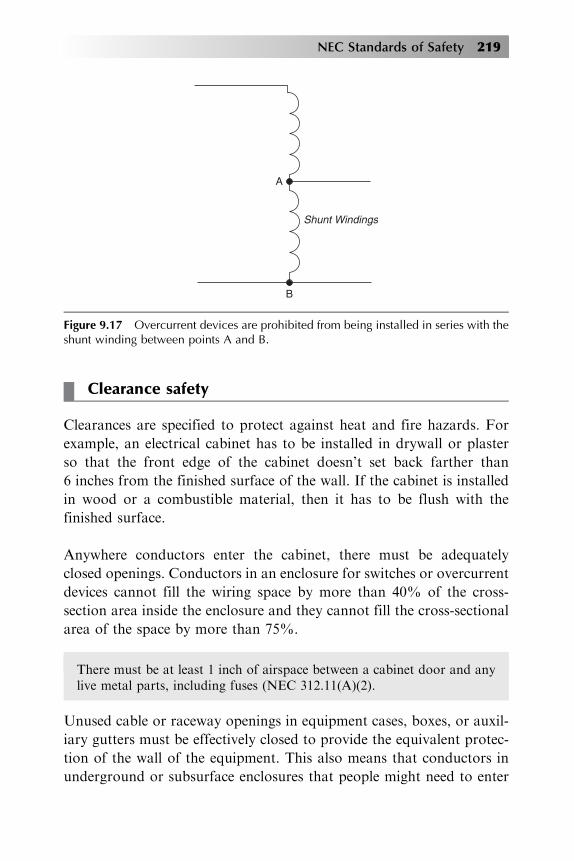
Overcurrent devices cannot be installed in series with the shunt winding
of the autotransformer between points A and B as shown in
Figure 9.17.
B
Shunt Windings
A
Figure 9.17 Overcurrent devices are prohibited from being installed in series with theshunt winding between points A and B.
NEC Standards of Safety 219
Clearance safety
Clearances are specified to protect against heat and fire hazards. For
example, an electrical cabinet has to be installed in drywall or plaster
so that the front edge of the cabinet doesn’t set back farther than
6 inches from the finished surface of the wall. If the cabinet is installed
in wood or a combustible material, then it has to be flush with the
finished surface.
Anywhere conductors enter the cabinet, there must be adequately
closed openings. Conductors in an enclosure for switches or overcurrent
devices cannot fill the wiring space by more than 40% of the cross-
section area inside the enclosure and they cannot fill the cross-sectional
area of the space by more than 75%.
There must be at least 1 inch of airspace between a cabinet door and anylive metal parts, including fuses (NEC 312.11(A)(2).
Unused cable or raceway openings in equipment cases, boxes, or auxil-
iary gutters must be effectively closed to provide the equivalent protec-
tion of the wall of the equipment. This also means that conductors in
underground or subsurface enclosures that people might need to enter

220 Electrical Safety Code Manual
to install or maintain equipment have to be racked. This provides safe
and easy access. Also, internal parts of electrical equipment, such as
busbars, insulators, or wiring terminals cannot be damaged, bent, bro-
ken or cut, or contaminated by materials like paint or plaster, abrasives,
or corrosive residues.
Switchboards that are not totally enclosed must have a clearance of
3 feet from the top of the switchboard to a ceiling constructed of
wood, drywall, or any other combustible material. Transformers must
be readily accessible to qualified personnel for inspection and mainte-
nance per NEC 450.13. Dry-type transformers rated less than 600 V
and 112½ kVA must be separated from combustible materials, such
as drywall, by a fire-resistant, heat insulating barrier or a minimum
of 12 inches of open space. If transformers exceed 112½ kVA,
Class 155 then they must be separated by either the fire-resistant barrier
or 6 feet horizontally and 12 feet vertically from combustible
materials.
ARC WELDING
Welders can encounter major health hazards including fumes and
gases, arc rays and sparks, and electric shock. Arc welding uses a
welding power supply to create an electric arc between two surfaces
or by a heating rod with an electrode until it melts from overcurrent.
They can use either DC or AC current, and consumable or non-
consumable electrodes. Either method results in a large momentary
current draw. NEC Article 630 focuses on adequately sizing the
conductors and circuit protection to handle these welding loads.
The supply conductors for welders cannot be less than the current
values calculated by multiplying the rated primary current in amperes
that are shown on the welding machine nameplate by the factor for the
machine’s duty cycle that is listed in NEC 630-11(A). Each welder
must have overcurrent protection rated no less than 200% of the rated
primary current of the welder. Because of the safety risks from over-
heating conductors, welding cable has requirements other conductors
don’t have. For example, the insulation on these cables must be
flame-retardant.

NEC Standards of Safety 221
Regardless of the application, conductors and loads must be sized
based on the National Electrical Code to guard against hazards. Over-
current protection, insulation, airspace, and distance from combustible
materials all work together to reduce the risk of shock, overheating, and
fire damage. When you are installing basic electrical elements, remem-
ber that both your safety and the safety of the people and property
you are working for are at risk. Since NEC standards are established
to ensure installations that are focused on safety, compliance is both
mandatory and your best way of reducing your professional and per-
sonal risk (Figure 9.00).
CONDUCTOR AND
OVERCURRENT
PROTECTION
SIZING
Determine conductor sizing and overcurrent protection based on:
1. Continuous loads 2. Terminal temperature ratings 3. Conductor insulation 4. Conductor ampacity 5. Special application 6. System voltage
Size overcurrent protection devices in accordance with Sections210-20(a), 215-3, and 384-16(d)
Select the proper conductor that complies with Sections 110-14(c),210-19(a), 215-2, and 230-42(a). Section 110-14(c) requires the circuit conductors to be sized according to Table 310-16. Sections 210-19(a), 215-2 and 230-42(a) required the conductor to be sized no less than 100% of the non-continuous load, plus 125% of the continuous load.
Protect conductors against overcurrent in accordance withSection 240-3. Section 240-3.
Figure 9.00 Conductor and Over Current Protection Tips.