chapter 9 welding, bonding, and the design of permanent joints...welding symbols arrow side of a...
TRANSCRIPT

Chapter 9
Welding, Bonding, and the
Design of Permanent
Joints

Chapter Outline
Shigley’s Mechanical Engineering Design
Introduction
Shigley’s Mechanical Engineering Design
Welding is the process of joining two pieces of metal
together by hammering, pressure or fusion. Filler metal
may or may not be used.
The strongest and most common method of permanently
joining steel components together.
Arc welding is the most important since it is adaptable to
various manufacturing environments and is relatively
cheap.
A weldment is fabricated by welding together a collection
of metal shapes.

Shigley’s Mechanical Engineering Design
Introduction
A pool of molten metal in which the components and
electrode material coalesce, forming a homogeneous
whole (ideally) when the pool later resolidifies.
The materials of components and electrode must be
compatible from the point of view of strength, ductility
and metallurgy.

Welding Symbols
Welding symbol standardized by American Welding Society
Specifies details of weld on machine drawings
Shigley’s Mechanical Engineering Design
Fig. 9–4

AWS Standard
Weld symbol
◦ Graphic symbol that indicates weld required
Welding symbol
◦ Following eight elements:
Reference line (required)
Arrow (required)
Basic weld symbols
Dimensions and other data
Supplementary symbols
Finish symbols
Tail
Other specifications

Welding Symbol Components

Welding Symbols
Shigley’s Mechanical Engineering Design
Fig. 9–1

Joints in drawings may be indicated:
•by detailed sketches, showing every dimension
•by symbolic representation
Weld symbols on drawings

Elementary Weld Symbols
Square Groove Weld
Single V Groove Weld

Single Bevel Groove Weld
Single V Groove Weld with Broad Root Face
Elementary Weld Symbols

Single Bevel Groove Weld with Broad Root Face
Single U Groove Weld
Elementary Weld Symbols
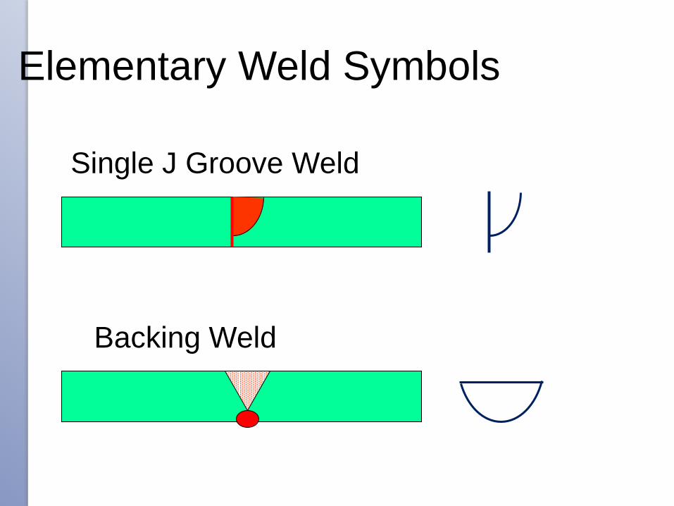
Single J Groove Weld
Backing Weld
Elementary Weld Symbols
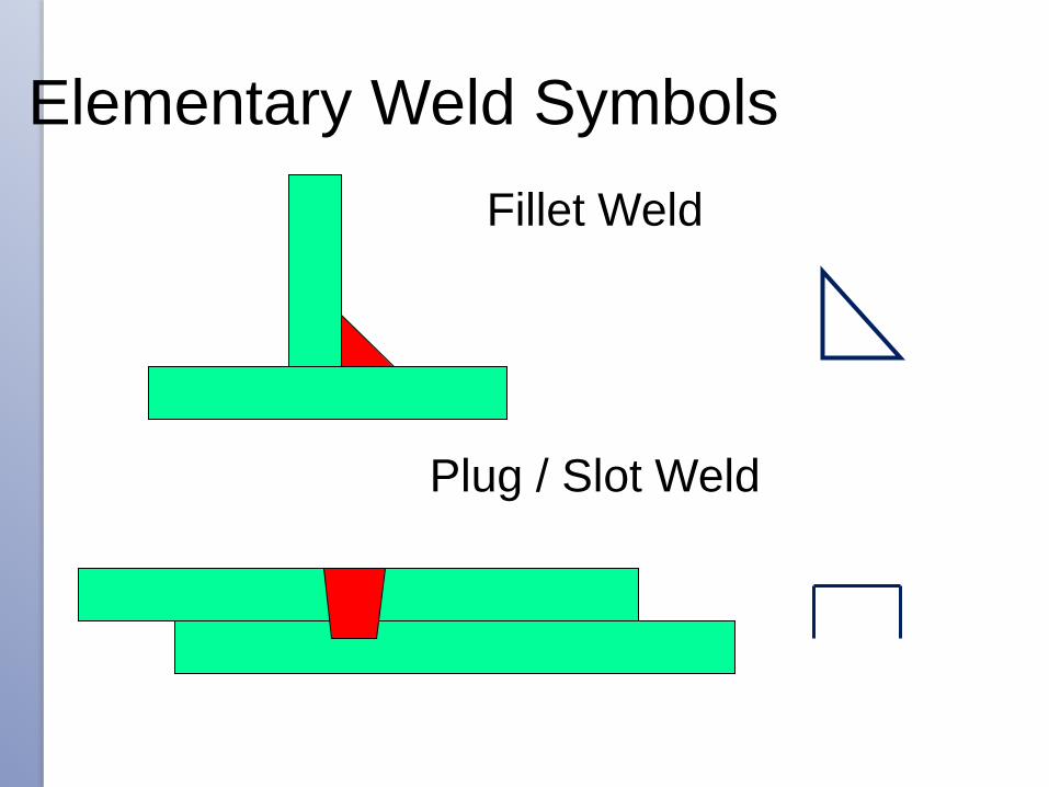
Fillet Weld
Plug / Slot Weld
Elementary Weld Symbols

Spot Weld
Seam Weld
Elementary Weld Symbols

Edge Weld
Surfacing
Elementary Weld Symbols

SUPPLEMENTARY SYMBOLS
Flat
Convex Concave
Weld Profile

SUPPLEMENTARY SYMBOLS
Toes blended
smoothly Permanent Backing
Strip
M
Removable
Backing Strip
MR

SUPPLEMENTARY SYMBOLS
Peripheral Welds

Welding Symbols
Arrow side of a joint is the line, side, area, or near member to
which the arrow points
The side opposite the arrow side is the other side
Shape of weld is shown with the symbols below
Shigley’s Mechanical Engineering Design
Fig. 9–2

Welding Symbol Examples
Shigley’s Mechanical Engineering Design
Weld leg size of 5 mm
Fillet weld
Both sides
Intermittent and
staggered 60 mm along
on 200 mm centers
Leg size of 5 mm
On one side only
(outside)
Circle indicates all the
way around

Welding Symbol Examples
Shigley’s Mechanical Engineering Design
Fig. 9–5
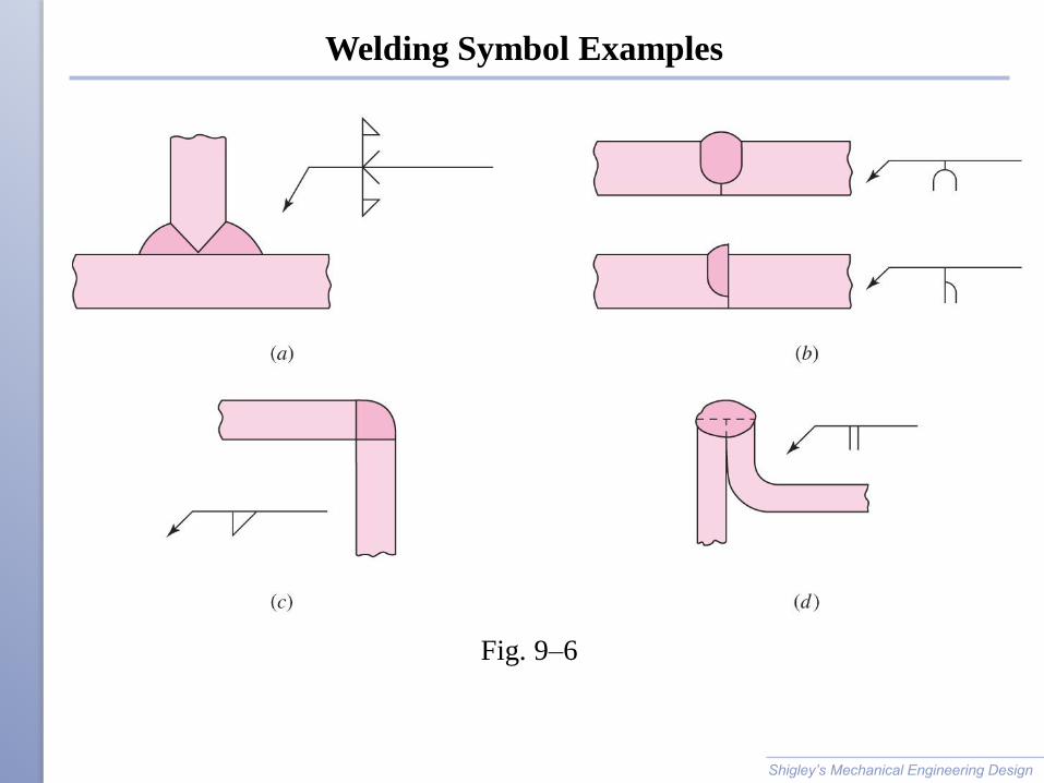
Welding Symbol Examples
Shigley’s Mechanical Engineering Design
Fig. 9–6

Tensile Butt Joint
Simple butt joint loaded in tension or compression
Stress is normal stress
Throat h does not include extra reinforcement
Reinforcement adds some strength for static loaded joints
Reinforcement adds stress concentration and should be ground
off for fatigue loaded joints
Shigley’s Mechanical Engineering Design Fig. 9–7a

Shear Butt Joint
Simple butt joint loaded in shear
Average shear stress
Shigley’s Mechanical Engineering Design
Fig. 9–7b

Transverse Fillet Weld
Joint loaded in tension
Weld loading is complex
Shigley’s Mechanical Engineering Design
Fig. 9–8
Fig. 9–9

Transverse Fillet Weld
Summation of forces
Law of sines
Solving for throat thickness t
Shigley’s Mechanical Engineering Design
Fig. 9–9

Transverse Fillet Weld
Nominal stresses at angle q
Von Mises Stress at angle q
Shigley’s Mechanical Engineering Design
Fig. 9–9

Transverse Fillet Weld
Largest von Mises stress occurs at q = 62.5º with value of
s' = 2.16F/(hl)
Maximum shear stress occurs at q = 67.5º with value of
tmax = 1.207F/(hl)
Shigley’s Mechanical Engineering Design
Fig. 9–9

Parallel Fillet Welds
Same equation also applies for simpler case of simple shear
loading in fillet weld
Shigley’s Mechanical Engineering Design
Fig. 9–11
Throat Width
= 0.707h

Fillet Welds Loaded in Torsion
Fillet welds carrying both direct shear V and moment M
Primary shear
Secondary shear
A is the throat area of all welds
r is distance from centroid of weld group to point of interest
J is second polar moment of area of weld group about centroid of group
Shigley’s Mechanical Engineering Design
Fig. 9–12

Shigley’s Mechanical Engineering Design

Example of Finding A and J
Rectangles represent
throat areas. t = 0.707 h
Shigley’s Mechanical Engineering Design
Fig. 9–13
Using the parallel axis theorem, the second polar moment of area of the weld group is
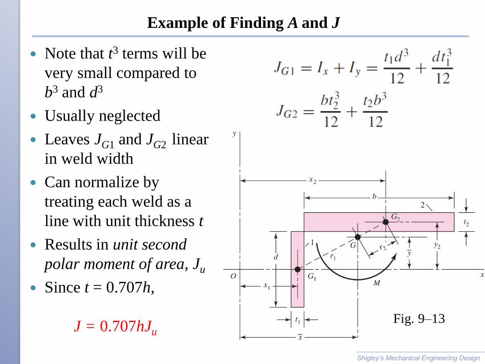
Example of Finding A and J
Note that t3 terms will be
very small compared to
b3 and d3
Usually neglected
Leaves JG1 and JG2 linear
in weld width
Can normalize by
treating each weld as a
line with unit thickness t
Results in unit second
polar moment of area, Ju
Since t = 0.707h,
J = 0.707hJu
Shigley’s Mechanical Engineering Design
Fig. 9–13
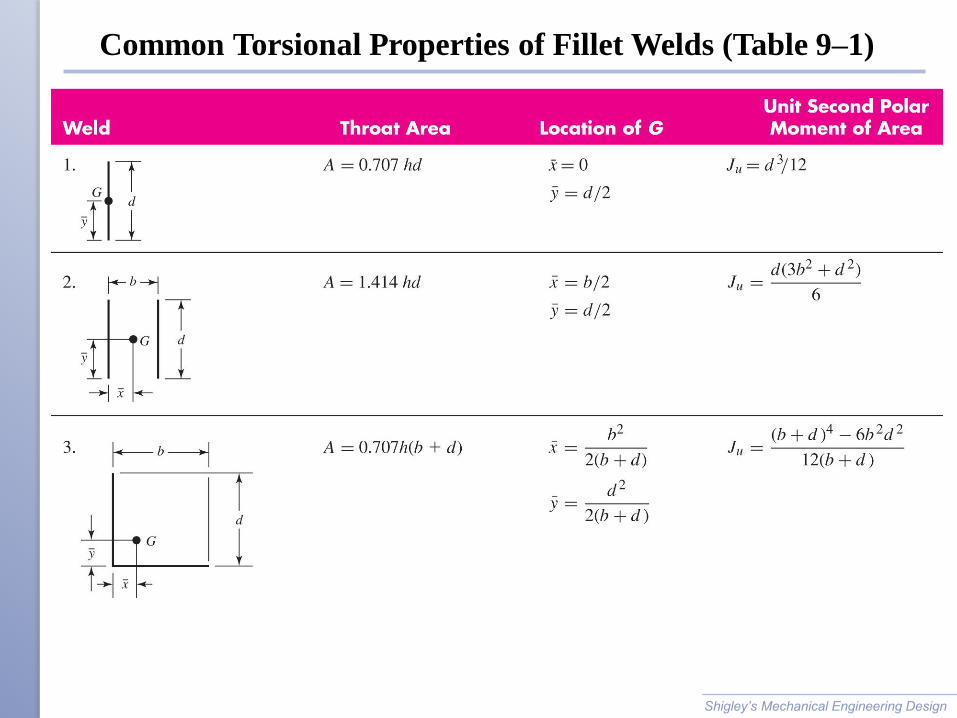
Common Torsional Properties of Fillet Welds (Table 9–1)
Shigley’s Mechanical Engineering Design

Common Torsional Properties of Fillet Welds (Table 9–1)
Shigley’s Mechanical Engineering Design

Example 9–1
Shigley’s Mechanical Engineering Design
Fig. 9–14

Example 9–1
Shigley’s Mechanical Engineering Design
Fig. 9–15

Example 9–1
Shigley’s Mechanical Engineering Design
Fig. 9–15

Example 9–1
Shigley’s Mechanical Engineering Design
Fig. 9–15

Example 9–1
Shigley’s Mechanical Engineering Design

Example 9–1
Shigley’s Mechanical Engineering Design
Fig. 9–16

Example 9–1
Shigley’s Mechanical Engineering Design Fig. 9–16

Fillet Welds Loaded in Bending
Fillet welds carry both shear V and moment M
Shigley’s Mechanical Engineering Design
Fig. 9–17

Bending Properties of Fillet Welds (Table 9–2)
Shigley’s Mechanical Engineering Design
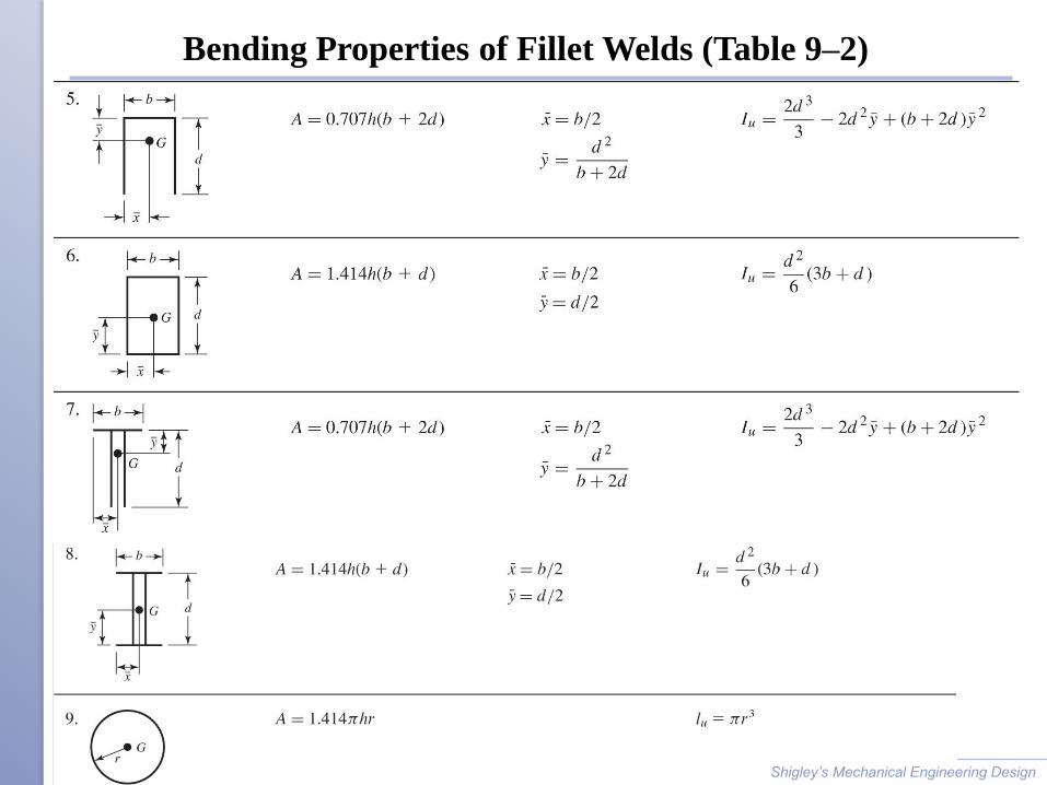
Bending Properties of Fillet Welds (Table 9–2)
Shigley’s Mechanical Engineering Design

Strength of Welded Joints
Must check for failure in parent material and in weld
Weld strength is dependent on choice of electrode material
Weld material is often stronger than parent material
Parent material experiences heat treatment near weld
Cold drawn parent material may become more like hot rolled in
vicinity of weld
Often welded joints are designed by following codes rather than
designing by the conventional factor of safety method
Shigley’s Mechanical Engineering Design

Minimum Weld-Metal Properties (Table 9–3)
Shigley’s Mechanical Engineering Design

Stresses Permitted by the AISC Code for Weld Metal
Shigley’s Mechanical Engineering Design
Table 9–4

Allowable Load or Various Sizes of Fillet Welds (Table 9–6)
Shigley’s Mechanical Engineering Design

Minimum Fillet Weld Size, h (Table 9–6)
Shigley’s Mechanical Engineering Design

Example 9–2
Shigley’s Mechanical Engineering Design
Fig. 9–18
Table A-20, Sy = 27.5 kpsi

Example 9–2
Shigley’s Mechanical Engineering Design
h =3/8=0.375 in
t = 1/2 in
l = 2 in

Example 9–2
Shigley’s Mechanical Engineering Design

Example 9–4
Shigley’s Mechanical Engineering Design
Fig. 9–20
Table A-20,
Sy = 32 kpsi, Sut= 58 kpsi
Table 9-3,
Sy = 50 kpsi,
Sut= 62 kpsi

Example 9–4
Shigley’s Mechanical Engineering Design

Example 9–4
Shigley’s Mechanical Engineering Design
Eq. 5-21
Ssy= 0.577 Sy
Eq. 5-19

Example 9–4
Shigley’s Mechanical Engineering Design
Given n=3

Fatigue Stress-Concentration Factors
Kfs appropriate for application to shear stresses
Use for parent metal and for weld metal
Shigley’s Mechanical Engineering Design
For Welding codes, see the fatigue stress allowable in the AISI manual.

Example 9–5
Shigley’s Mechanical Engineering Design
Fig. 9–21
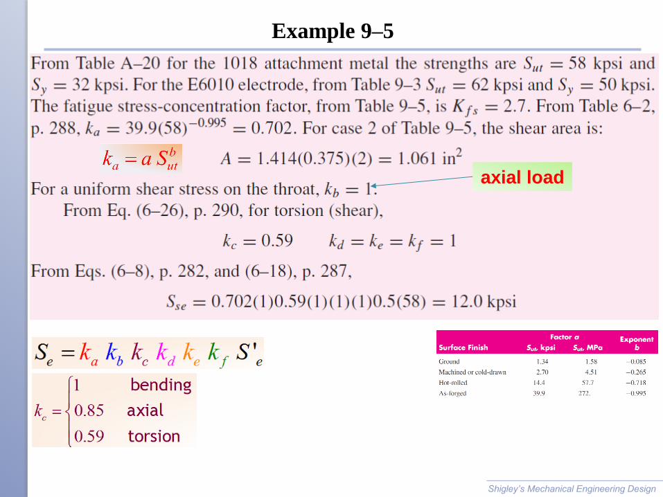
Example 9–5
Shigley’s Mechanical Engineering Design
axial load

Example 9–5
Shigley’s Mechanical Engineering Design

Example 9–6
Shigley’s Mechanical Engineering Design
Fig. 9–22
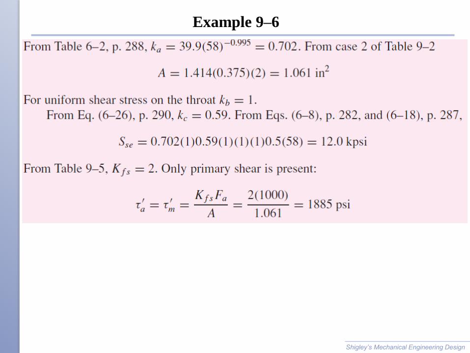
Example 9–6
Shigley’s Mechanical Engineering Design

Example 9–6
Shigley’s Mechanical Engineering Design

Resistance Welding
Welding by passing an electric current through parts that are
pressed together
Common forms are spot welding and seam welding
Failure by shear of weld or tearing of member
Avoid loading joint in tension to avoid tearing
Shigley’s Mechanical Engineering Design Fig. 9–23

Adhesive Bonding
Adhesive bonding has unique advantages
Reduced weight, sealing capabilities, reduced part count, reduced
assembly time, improved fatigue and corrosion resistance, reduced
stress concentration associated with bolt holes
Shigley’s Mechanical Engineering Design
Fig. 9–24

Types of Adhesives
May be classified by
◦ Chemistry
Epoxies, polyurethanes, polyimides
◦ Form
Paste, liquid, film, pellets, tape
◦ Type
Hot melt, reactive hot melt, thermosetting, pressure sensitive,
contact
◦ Load-carrying capability
Structural, semi-structural, non-structural
Shigley’s Mechanical Engineering Design

Mechanical Performance of Various Types of Adhesives
Shigley’s Mechanical Engineering Design
Table 9–7

Stress Distributions
Adhesive joints are much stronger
in shear loading than tensile loading
Lap-shear joints are important for
test specimens and for practical
designs
Simplest analysis assumes uniform
stress distribution over bonded area
Most joints actually experience
significant peaks of stress
Shigley’s Mechanical Engineering Design Fig. 9–25

Double-lap Joint
Classic analysis of double-lap joint known as shear-lag model
Double joint eliminates complication of bending from
eccentricity
Shigley’s Mechanical Engineering Design Fig. 9–26

Double-lap Joint
Shear-stress distribution is given by
Shigley’s Mechanical Engineering Design Fig. 9–26b

Example 9–7
Shigley’s Mechanical Engineering Design
Fig. 9–26

Example 9–7
Shigley’s Mechanical Engineering Design

Example 9–7
Shigley’s Mechanical Engineering Design
Fig. 9–27
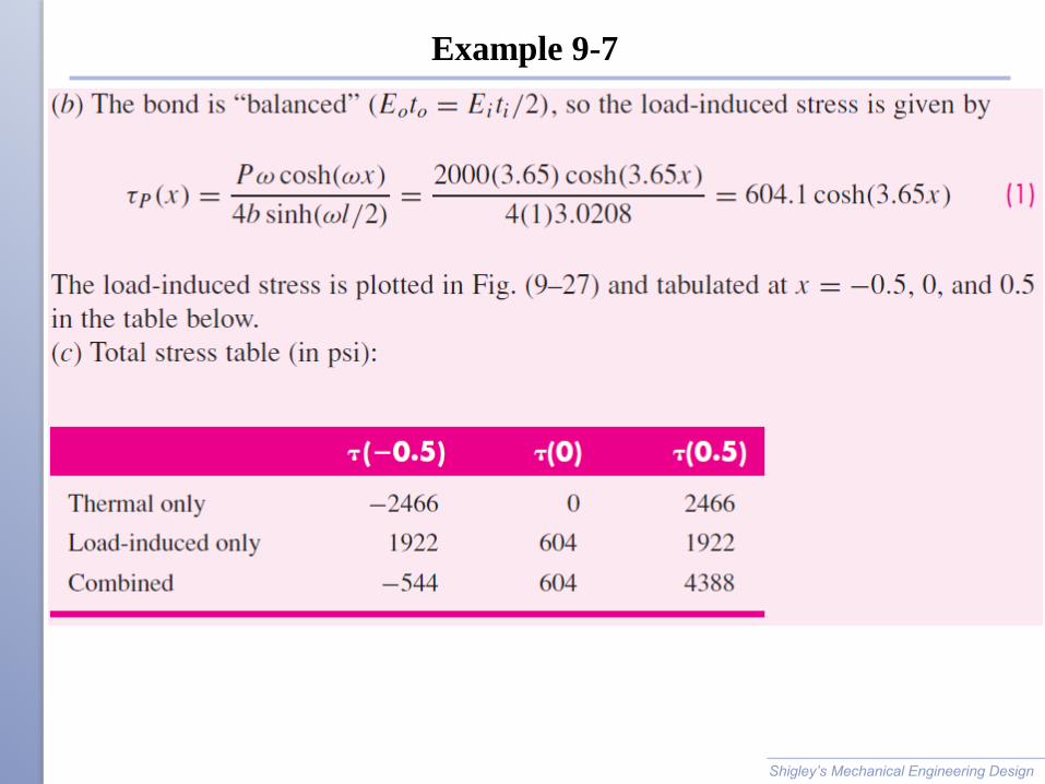
Example 9-7
Shigley’s Mechanical Engineering Design

Example 9-7
Shigley’s Mechanical Engineering Design

Single-lap Joint
Eccentricity introduces bending
Bending can as much as double the resulting shear stresses
Near ends of joint peel stresses can be large, causing joint failure
Shigley’s Mechanical Engineering Design Fig. 9–28

Single-lap Joint
Shear and peal stresses in single-lap joint, as calculated by Goland
and Reissner
Volkersen curve is for double-lap joint
Shigley’s Mechanical Engineering Design Fig. 9–28

Adhesive Joint Design Guidelines
Design to place bondline in shear, not peel.
Use adhesives with adequate ductility to reduce stress
concentrations and increase toughness to resist debond
propagation.
Recognize environmental limitations of adhesives and surface
preparation.
Design to facilitate inspection.
Allow sufficient bond area to tolerate some debonding before
becoming critical.
Attempt to bond to multiple surfaces to support loads in any
direction.
Consider using adhesives in conjunction with spot welds, rivets, or
bolts.
Shigley’s Mechanical Engineering Design

Design Ideas for Improved Bonding
Shigley’s Mechanical Engineering Design Fig. 9–29

Design Ideas for Improved Bonding
Shigley’s Mechanical Engineering Design Fig. 9–29

Design Ideas for Improved Bonding
Shigley’s Mechanical Engineering Design Fig. 9–29