chapter 4harmanani.github.io/classes/csc320/notes/ch04.pdf · cpu overview. chapter 4 —the ......
TRANSCRIPT
COMPUTERORGANIZATION AND DESIGNThe Hardware/Software Interface
ARMEdition
Chapter 4The Processor
Chapter 4 — The Processor — 2
Introductionn CPU performance factors
n Instruction countn Determined by ISA and compiler
n CPI and Cycle timen Determined by CPU hardware
n We will examine two LEGv8 implementationsn A simplified versionn A more realistic pipelined version
n Simple subset, shows most aspectsn Memory reference: LDUR, STURn Arithmetic/logical: add, sub, and, or, sltn Control transfer: beq, j
§4.1 Introduction
Chapter 4 — The Processor — 3
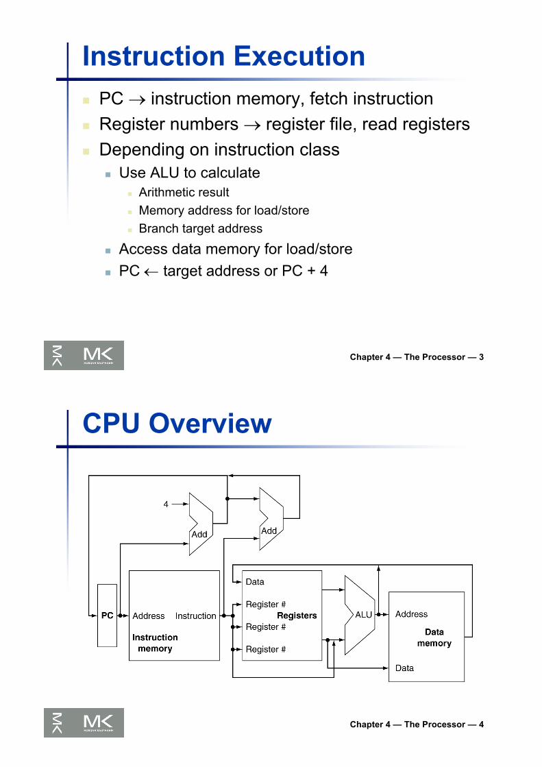
Instruction Executionn PC ® instruction memory, fetch instructionn Register numbers ® register file, read registersn Depending on instruction class
n Use ALU to calculaten Arithmetic resultn Memory address for load/storen Branch target address
n Access data memory for load/storen PC ¬ target address or PC + 4
Chapter 4 — The Processor — 4
CPU Overview
Chapter 4 — The Processor — 5
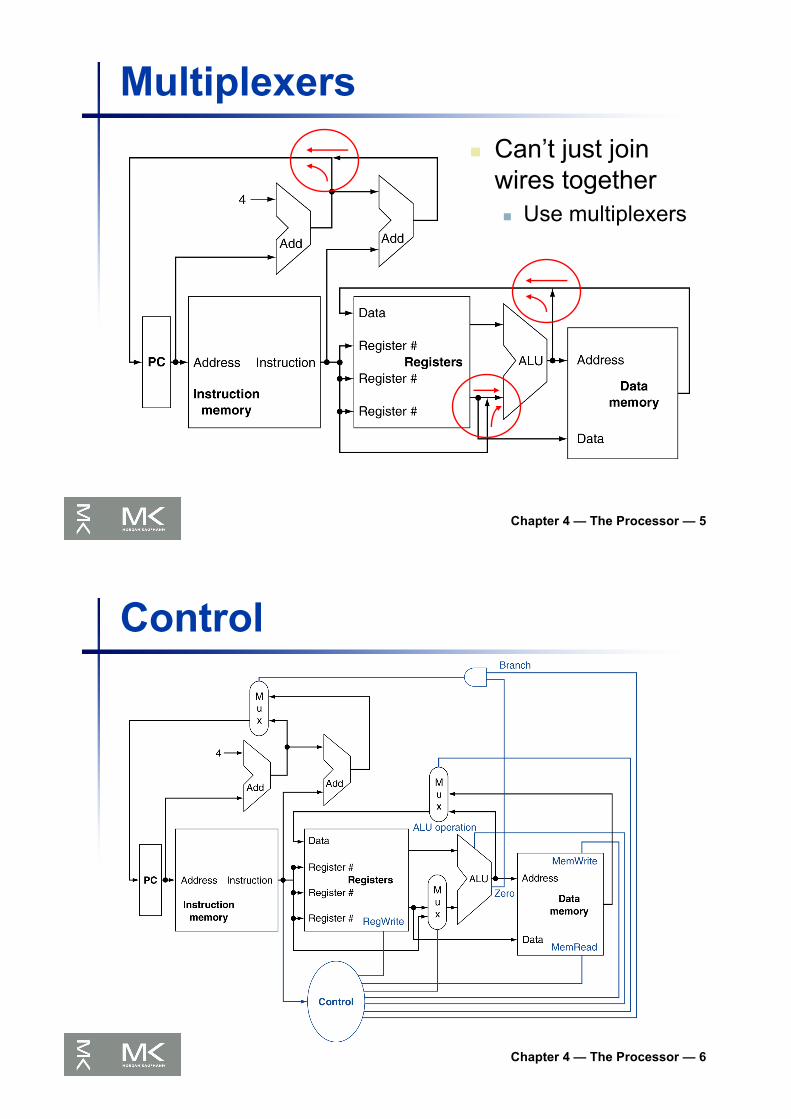
Multiplexersn Can’t just join
wires togethern Use multiplexers
Chapter 4 — The Processor — 6
Control

Chapter 4 — The Processor — 7
Logic Design Basics§4.2 Logic D
esign Conventions
n Information encoded in binaryn Low voltage = 0, High voltage = 1n One wire per bitn Multi-bit data encoded on multi-wire buses
n Combinational elementn Operate on datan Output is a function of input
n State (sequential) elementsn Store information
Chapter 4 — The Processor — 8
Combinational Elements
n AND-gaten Y = A & BAB
Y
I0I1
YMux
S
n Multiplexern Y = S ? I1 : I0
A
B
Y+
A
B
YALU
F
n Addern Y = A + B
n Arithmetic/Logic Unitn Y = F(A, B)
Chapter 4 — The Processor — 9
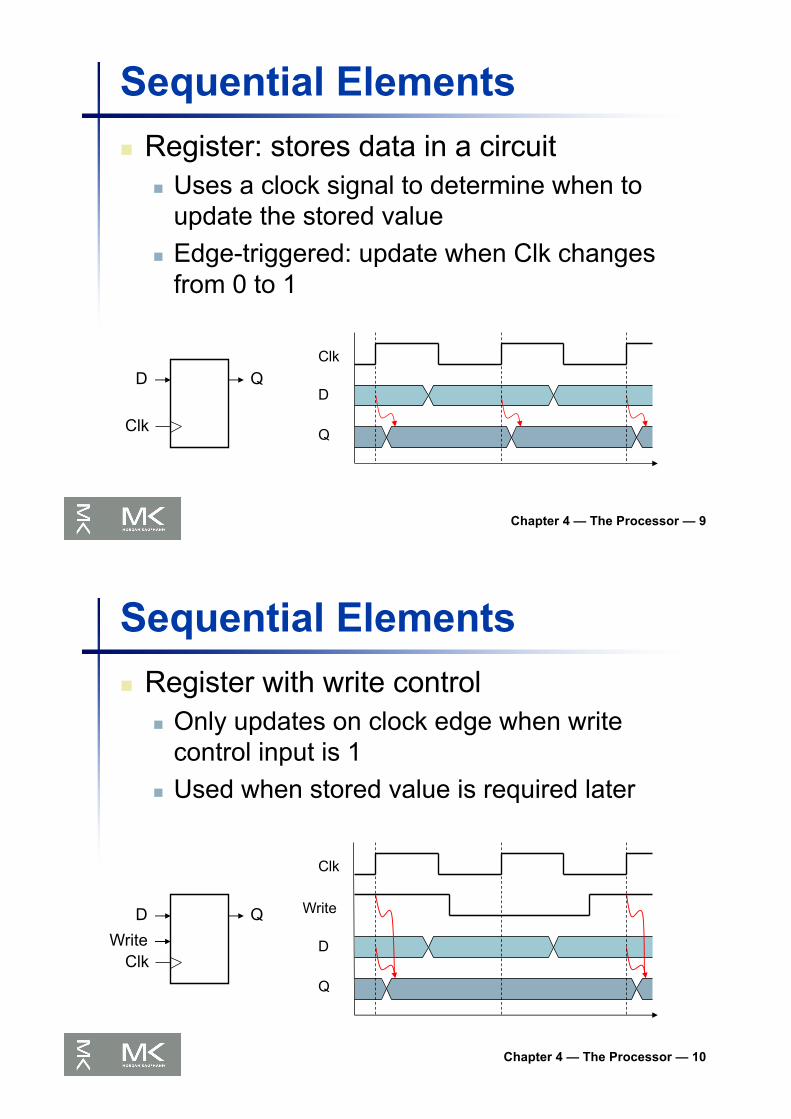
Sequential Elementsn Register: stores data in a circuit
n Uses a clock signal to determine when to update the stored value
n Edge-triggered: update when Clk changes from 0 to 1
D
Clk
QClk
D
Q
Chapter 4 — The Processor — 10
Sequential Elementsn Register with write control
n Only updates on clock edge when write control input is 1
n Used when stored value is required later
D
Clk
Q
Write
Write
D
Q
Clk
Chapter 4 — The Processor — 11
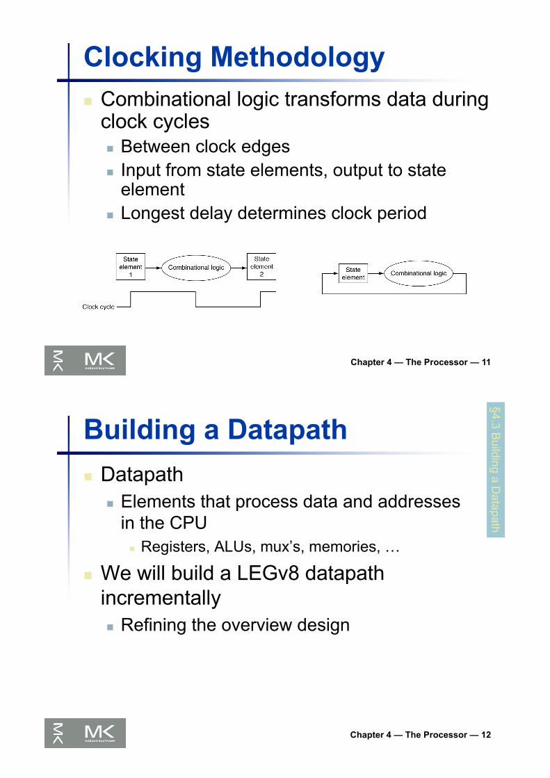
Clocking Methodologyn Combinational logic transforms data during
clock cyclesn Between clock edgesn Input from state elements, output to state
elementn Longest delay determines clock period
Chapter 4 — The Processor — 12
Building a Datapathn Datapath
n Elements that process data and addressesin the CPU
n Registers, ALUs, mux’s, memories, …
n We will build a LEGv8 datapath incrementallyn Refining the overview design
§4.3 Building a D
atapath
Chapter 4 — The Processor — 13
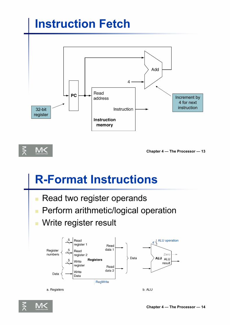
Instruction Fetch
32-bit register
Increment by 4 for next instruction
Chapter 4 — The Processor — 14
R-Format Instructionsn Read two register operandsn Perform arithmetic/logical operationn Write register result

Chapter 4 — The Processor — 15
Load/Store Instructionsn Read register operandsn Calculate address using 16-bit offset
n Use ALU, but sign-extend offsetn Load: Read memory and update registern Store: Write register value to memory
Chapter 4 — The Processor — 16
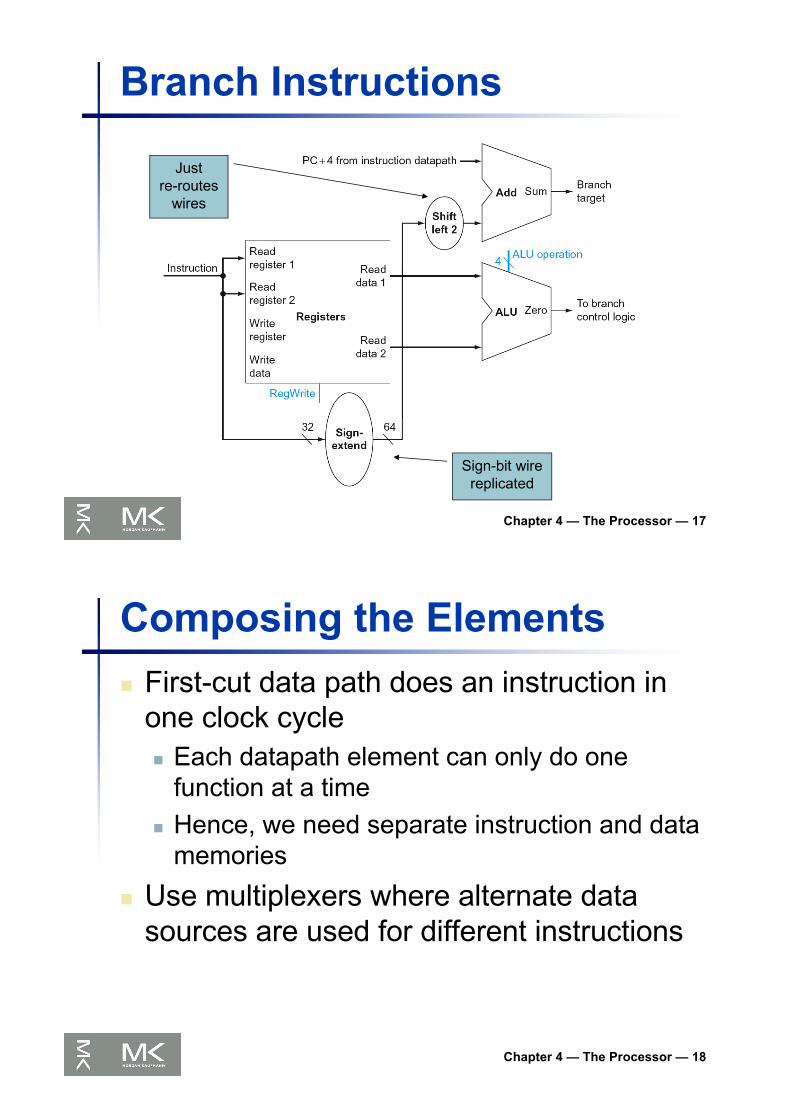
Branch Instructionsn Read register operandsn Compare operands
n Use ALU, subtract and check Zero output
n Calculate target addressn Sign-extend displacementn Shift left 2 places (word displacement)n Add to PC + 4
n Already calculated by instruction fetch
Chapter 4 — The Processor — 17
Branch Instructions
Justre-routes
wires
Sign-bit wire replicated
Chapter 4 — The Processor — 18
Composing the Elementsn First-cut data path does an instruction in
one clock cyclen Each datapath element can only do one
function at a timen Hence, we need separate instruction and data
memories
n Use multiplexers where alternate data sources are used for different instructions
Chapter 4 — The Processor — 19
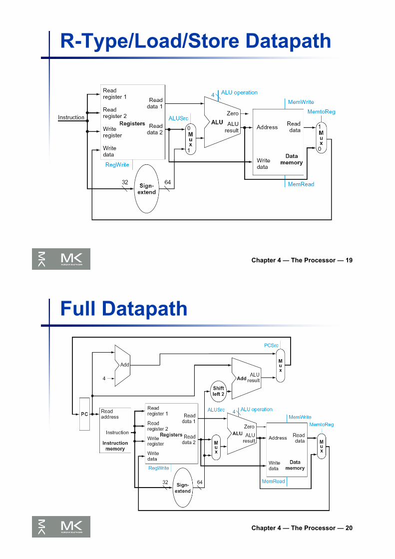
R-Type/Load/Store Datapath
Chapter 4 — The Processor — 20
Full Datapath
Chapter 4 — The Processor — 21
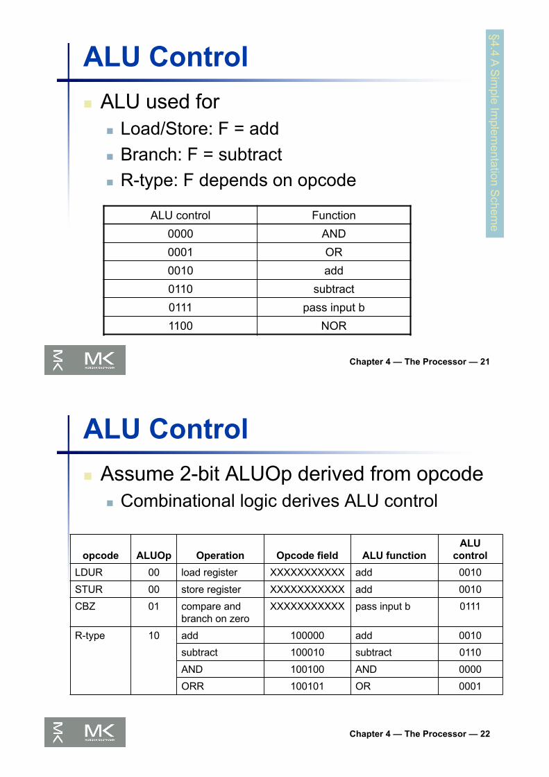
ALU Controln ALU used for
n Load/Store: F = addn Branch: F = subtractn R-type: F depends on opcode
§4.4 A Sim
ple Implem
entation Schem
eALU control Function
0000 AND
0001 OR
0010 add
0110 subtract
0111 pass input b
1100 NOR
Chapter 4 — The Processor — 22
ALU Controln Assume 2-bit ALUOp derived from opcode
n Combinational logic derives ALU control
opcode ALUOp Operation Opcode field ALU functionALU
controlLDUR 00 load register XXXXXXXXXXX add 0010
STUR 00 store register XXXXXXXXXXX add 0010
CBZ 01 compare and branch on zero
XXXXXXXXXXX pass input b 0111
R-type 10 add 100000 add 0010
subtract 100010 subtract 0110
AND 100100 AND 0000
ORR 100101 OR 0001

Chapter 4 — The Processor — 23
The Main Control Unitn Control signals derived from instruction
Chapter 4 — The Processor — 24
Datapath With Control
Chapter 4 — The Processor — 25
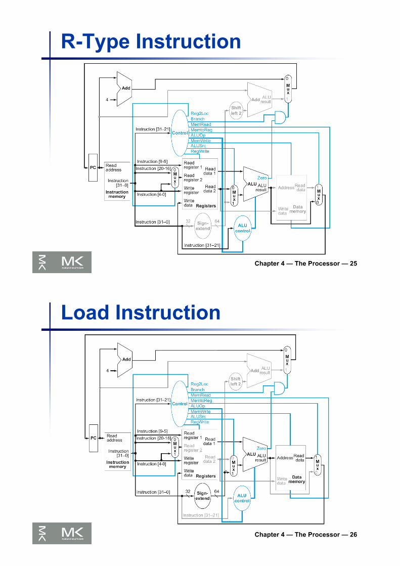
R-Type Instruction
Chapter 4 — The Processor — 26
Load Instruction
Chapter 4 — The Processor — 27
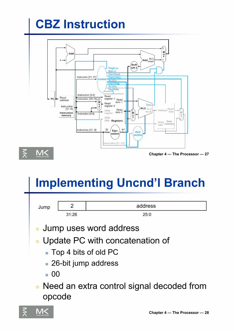
CBZ Instruction
Chapter 4 — The Processor — 28
Implementing Uncnd’l Branch
n Jump uses word addressn Update PC with concatenation of
n Top 4 bits of old PCn 26-bit jump addressn 00
n Need an extra control signal decoded from opcode
2 address31:26 25:0
Jump
Chapter 4 — The Processor — 29
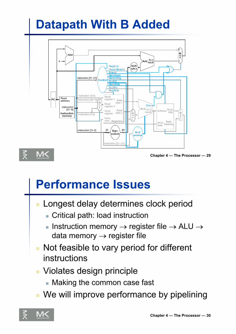
Datapath With B Added
Chapter 4 — The Processor — 30
Performance Issuesn Longest delay determines clock period
n Critical path: load instructionn Instruction memory ® register file ® ALU ®
data memory ® register file
n Not feasible to vary period for different instructions
n Violates design principlen Making the common case fast
n We will improve performance by pipelining

Chapter 4 — The Processor — 31
Pipelining Analogyn Pipelined laundry: overlapping execution
n Parallelism improves performance
§4.5 An O
verview of P
ipeliningn Four loads:n Speedup
= 8/3.5 = 2.3
n Non-stop:n Speedup
= 2n/0.5n + 1.5 ≈ 4= number of stages
Chapter 4 — The Processor — 32
LEGv8 Pipelinen Five stages, one step per stage
1. IF: Instruction fetch from memory2. ID: Instruction decode & register read3. EX: Execute operation or calculate address4. MEM: Access memory operand5. WB: Write result back to register

Chapter 4 — The Processor — 33
Pipeline Performancen Assume time for stages is
n 100ps for register read or writen 200ps for other stages
n Compare pipelined datapath with single-cycle datapath
Instr Instr fetch Register read
ALU op Memory access
Register write
Total time
LDUR 200ps 100 ps 200ps 200ps 100 ps 800ps
STUR 200ps 100 ps 200ps 200ps 700ps
R-format 200ps 100 ps 200ps 100 ps 600ps
CBZ 200ps 100 ps 200ps 500ps
Chapter 4 — The Processor — 34
Pipeline PerformanceSingle-cycle (Tc= 800ps)
Pipelined (Tc= 200ps)

Chapter 4 — The Processor — 35
Pipeline Speedupn If all stages are balanced
n i.e., all take the same timen Time between instructionspipelined
= Time between instructionsnonpipelined
Number of stages
n If not balanced, speedup is lessn Speedup due to increased throughput
n Latency (time for each instruction) does not decrease
Chapter 4 — The Processor — 36
Pipelining and ISA Designn LEGv8 ISA designed for pipelining
n All instructions are 32-bitsn Easier to fetch and decode in one cyclen c.f. x86: 1- to 17-byte instructions
n Few and regular instruction formatsn Can decode and read registers in one step
n Load/store addressingn Can calculate address in 3rd stage, access memory
in 4th stagen Alignment of memory operands
n Memory access takes only one cycle
Chapter 4 — The Processor — 37
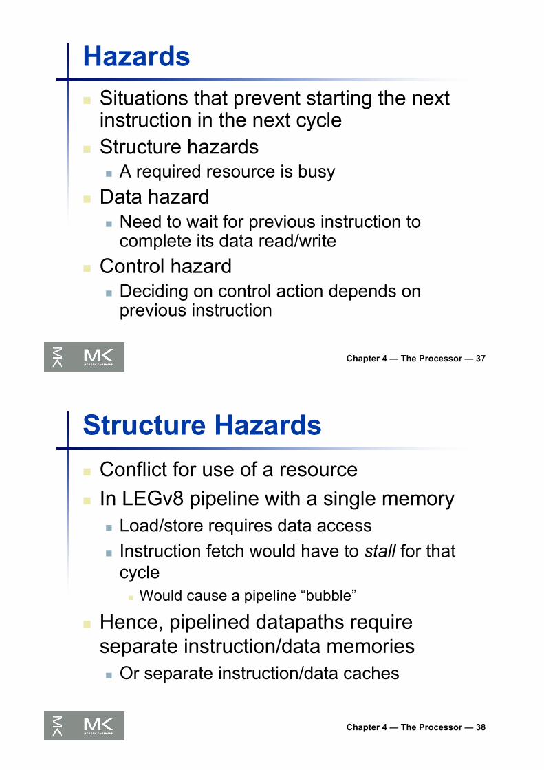
Hazardsn Situations that prevent starting the next
instruction in the next cyclen Structure hazards
n A required resource is busyn Data hazard
n Need to wait for previous instruction to complete its data read/write
n Control hazardn Deciding on control action depends on
previous instruction
Chapter 4 — The Processor — 38
Structure Hazardsn Conflict for use of a resourcen In LEGv8 pipeline with a single memory
n Load/store requires data accessn Instruction fetch would have to stall for that
cyclen Would cause a pipeline “bubble”
n Hence, pipelined datapaths require separate instruction/data memoriesn Or separate instruction/data caches
Chapter 4 — The Processor — 39
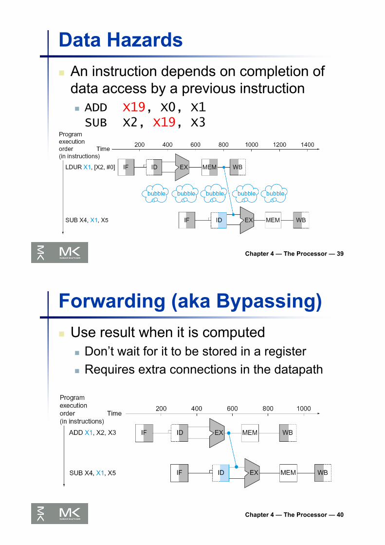
Data Hazardsn An instruction depends on completion of
data access by a previous instructionn ADD X19, X0, X1SUB X2, X19, X3
Chapter 4 — The Processor — 40
Forwarding (aka Bypassing)n Use result when it is computed
n Don’t wait for it to be stored in a registern Requires extra connections in the datapath

Chapter 4 — The Processor — 41
Load-Use Data Hazardn Can’t always avoid stalls by forwarding
n If value not computed when neededn Can’t forward backward in time!
Chapter 4 — The Processor — 42
Code Scheduling to Avoid Stallsn Reorder code to avoid use of load result in
the next instructionn C code for A = B + E; C = B + F;
LDUR X1, [X0,#0]
LDUR X2, [X0,#8]
ADD X3, X1, X2
STUR X3, [X0,#24]
LDUR X4, [X0,#16]
ADD X5, X1, X4
STUR X5, [X0,#32]
stall
stall
LDUR X1, [X0,#0]
LDUR X2, [X0,#8]
LDUR X4, [X0,#16]
ADD X3, X1, X2
STUR X3, [X0,#24]
ADD X5, X1, X4
STUR X5, [X0,#32]
11 cycles13 cycles

Chapter 4 — The Processor — 43
Control Hazardsn Branch determines flow of control
n Fetching next instruction depends on branch outcome
n Pipeline can’t always fetch correct instructionn Still working on ID stage of branch
n In LEGv8 pipelinen Need to compare registers and compute
target early in the pipelinen Add hardware to do it in ID stage
Chapter 4 — The Processor — 44
Stall on Branchn Wait until branch outcome determined
before fetching next instruction

Chapter 4 — The Processor — 45
Branch Predictionn Longer pipelines can’t readily determine
branch outcome earlyn Stall penalty becomes unacceptable
n Predict outcome of branchn Only stall if prediction is wrong
n In LEGv8 pipelinen Can predict branches not takenn Fetch instruction after branch, with no delay
Chapter 4 — The Processor — 46
More-Realistic Branch Predictionn Static branch prediction
n Based on typical branch behaviorn Example: loop and if-statement branches
n Predict backward branches takenn Predict forward branches not taken
n Dynamic branch predictionn Hardware measures actual branch behavior
n e.g., record recent history of each branch
n Assume future behavior will continue the trendn When wrong, stall while re-fetching, and update history

Chapter 4 — The Processor — 47
Pipeline Summary
n Pipelining improves performance by increasing instruction throughputn Executes multiple instructions in paralleln Each instruction has the same latency
n Subject to hazardsn Structure, data, control
n Instruction set design affects complexity of pipeline implementation
The BIG Picture
Chapter 4 — The Processor — 48
LEGv8 Pipelined Datapath
§4.6 Pipelined D
atapath and Control
WB
MEM
Right-to-left flow leads to hazards
Chapter 4 — The Processor — 49
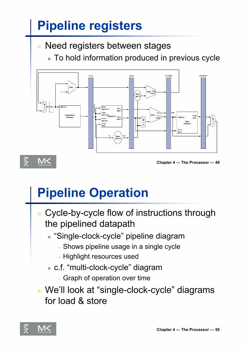
Pipeline registersn Need registers between stages
n To hold information produced in previous cycle
Chapter 4 — The Processor — 50
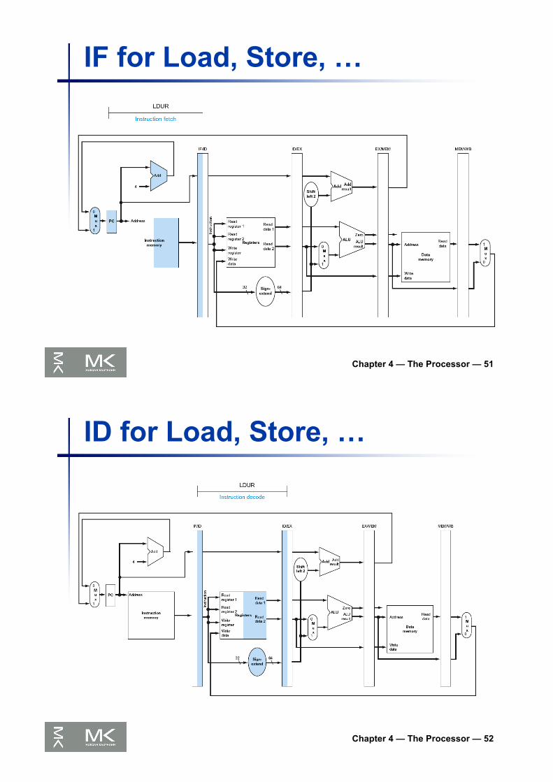
Pipeline Operationn Cycle-by-cycle flow of instructions through
the pipelined datapathn “Single-clock-cycle” pipeline diagram
n Shows pipeline usage in a single cyclen Highlight resources used
n c.f. “multi-clock-cycle” diagramn Graph of operation over time
n We’ll look at “single-clock-cycle” diagrams for load & store
Chapter 4 — The Processor — 51
IF for Load, Store, …
Chapter 4 — The Processor — 52
ID for Load, Store, …
Chapter 4 — The Processor — 53
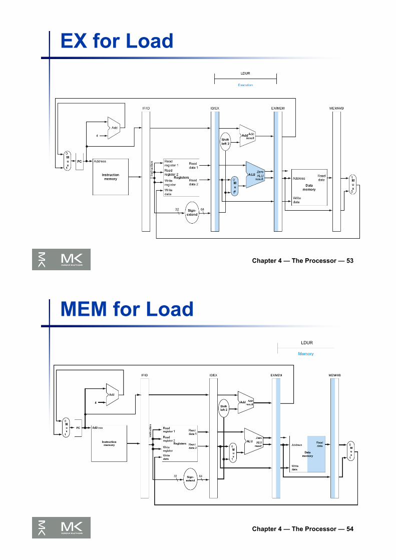
EX for Load
Chapter 4 — The Processor — 54
MEM for Load

Chapter 4 — The Processor — 55
WB for Load
Wrongregisternumber
Chapter 4 — The Processor — 56
Corrected Datapath for Load

Chapter 4 — The Processor — 57
EX for Store
Chapter 4 — The Processor — 58
MEM for Store

Chapter 4 — The Processor — 59
WB for Store
Chapter 4 — The Processor — 60
Multi-Cycle Pipeline Diagramn Form showing resource usage

Chapter 4 — The Processor — 61
Multi-Cycle Pipeline Diagramn Traditional form
Chapter 4 — The Processor — 62
Single-Cycle Pipeline Diagramn State of pipeline in a given cycle

Chapter 4 — The Processor — 63
Pipelined Control (Simplified)
Chapter 4 — The Processor — 64
Pipelined Controln Control signals derived from instruction
n As in single-cycle implementation
Chapter 4 — The Processor — 65
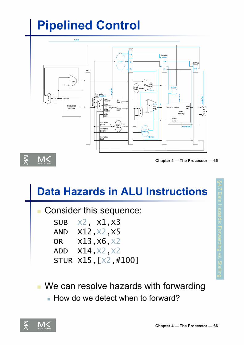
Pipelined Control
Chapter 4 — The Processor — 66
Data Hazards in ALU Instructionsn Consider this sequence:
SUB X2, X1,X3AND X12,X2,X5OR X13,X6,X2ADD X14,X2,X2STUR X15,[X2,#100]
n We can resolve hazards with forwardingn How do we detect when to forward?
§4.7 Data H
azards: Forwarding vs. S
talling
Chapter 4 — The Processor — 67
Dependencies & Forwarding
Chapter 4 — The Processor — 68
Detecting the Need to Forward
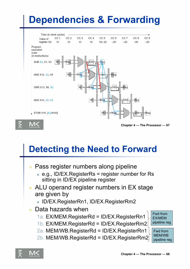
n Pass register numbers along pipelinen e.g., ID/EX.RegisterRs = register number for Rs
sitting in ID/EX pipeline registern ALU operand register numbers in EX stage
are given byn ID/EX.RegisterRn1, ID/EX.RegisterRm2
n Data hazards when1a. EX/MEM.RegisterRd = ID/EX.RegisterRn11b. EX/MEM.RegisterRd = ID/EX.RegisterRm22a. MEM/WB.RegisterRd = ID/EX.RegisterRn12b. MEM/WB.RegisterRd = ID/EX.RegisterRm2
Fwd fromEX/MEMpipeline reg
Fwd fromMEM/WBpipeline reg

Chapter 4 — The Processor — 69
Detecting the Need to Forwardn But only if forwarding instruction will write
to a register!n EX/MEM.RegWrite, MEM/WB.RegWrite
n And only if Rd for that instruction is not XZRn EX/MEM.RegisterRd ≠ 31,
MEM/WB.RegisterRd ≠ 31
Chapter 4 — The Processor — 70
Forwarding Paths

Chapter 4 — The Processor — 71
Forwarding ConditionsMux control Source ExplanationForwardA = 00 ID/EX The first ALU operand comes from the register file.
ForwardA = 10 EX/MEM The first ALU operand is forwarded from the prior ALU result.
ForwardA = 01 MEM/WB The first ALU operand is forwarded from data memory or an earlierALU result.
ForwardB = 00 ID/EX The second ALU operand comes from the register file.
ForwardB = 10 EX/MEM The second ALU operand is forwarded from the prior ALU result.
ForwardB = 01 MEM/WB The second ALU operand is forwarded from data memory or anearlier ALU result.
Chapter 4 — The Processor — 72
Double Data Hazardn Consider the sequence:
add X1,X1,X2add X1,X1,X3add X1,X1,X4
n Both hazards occurn Want to use the most recent
n Revise MEM hazard conditionn Only fwd if EX hazard condition isn’t true

Chapter 4 — The Processor — 73
Revised Forwarding Conditionn MEM hazard
n if (MEM/WB.RegWrite
and (MEM/WB.RegisterRd ≠ 31)
and not(EX/MEM.RegWrite and (EX/MEM.RegisterRd ≠ 31)
and (EX/MEM.RegisterRd ≠ ID/EX.RegisterRn1))
and (MEM/WB.RegisterRd = ID/EX.RegisterRn1)) ForwardA = 01
n if (MEM/WB.RegWrite
and (MEM/WB.RegisterRd ≠ 31)
and not(EX/MEM.RegWrite and (EX/MEM.RegisterRd ≠ 31)
and (EX/MEM.RegisterRd ≠ ID/EX.RegisterRm2))
and (MEM/WB.RegisterRd = ID/EX.RegisterRm2)) ForwardB = 01
Chapter 4 — The Processor — 74
Datapath with Forwarding
Chapter 4 — The Processor — 75
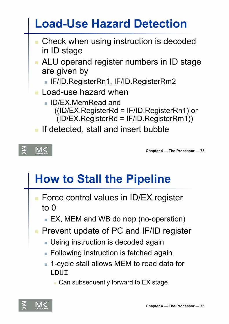
Load-Use Hazard Detectionn Check when using instruction is decoded
in ID stagen ALU operand register numbers in ID stage
are given byn IF/ID.RegisterRn1, IF/ID.RegisterRm2
n Load-use hazard whenn ID/EX.MemRead and
((ID/EX.RegisterRd = IF/ID.RegisterRn1) or(ID/EX.RegisterRd = IF/ID.RegisterRm1))
n If detected, stall and insert bubble
Chapter 4 — The Processor — 76
How to Stall the Pipelinen Force control values in ID/EX register
to 0n EX, MEM and WB do nop (no-operation)
n Prevent update of PC and IF/ID registern Using instruction is decoded againn Following instruction is fetched againn 1-cycle stall allows MEM to read data for LDUI
n Can subsequently forward to EX stage
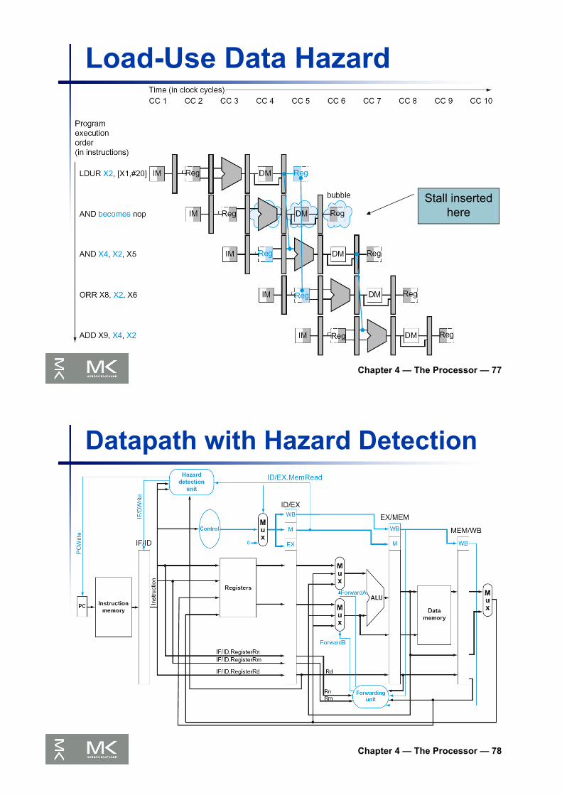
Chapter 4 — The Processor — 77
Load-Use Data Hazard
Stall inserted here
Chapter 4 — The Processor — 78
Datapath with Hazard Detection

Chapter 4 — The Processor — 79
Stalls and Performance
n Stalls reduce performancen But are required to get correct results
n Compiler can arrange code to avoid hazards and stallsn Requires knowledge of the pipeline structure
The BIG Picture
Chapter 4 — The Processor — 80
Branch Hazardsn If branch outcome determined in MEM
§4.8 Control H
azards
PC
Flush theseinstructions(Set controlvalues to 0)

Chapter 4 — The Processor — 81
Reducing Branch Delayn Move hardware to determine outcome to ID
stagen Target address addern Register comparator
n Example: branch taken36: SUB X10, X4, X840: CBZ X1, X3, 844: AND X12, X2, X548: ORR X13, X2, X652: ADD X14, X4, X256: SUB X15, X6, X7
...72: LDUR X4, [X7,#50]
Chapter 4 — The Processor — 82
Example: Branch Taken
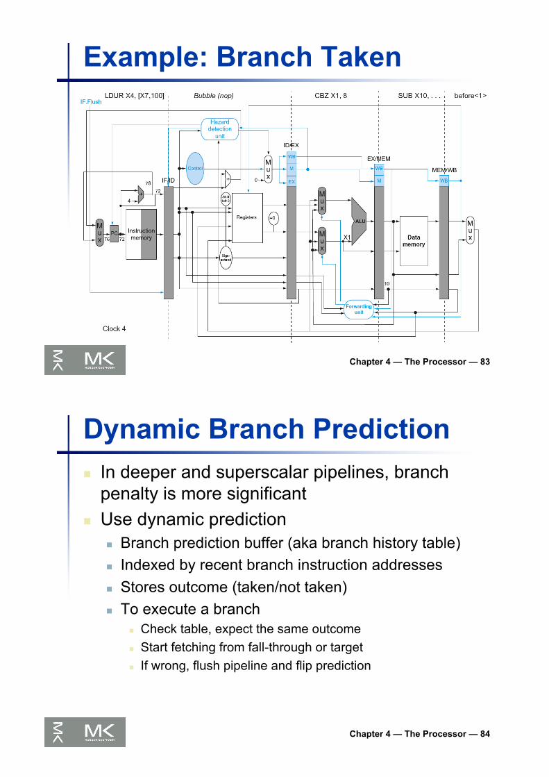
Chapter 4 — The Processor — 83
Example: Branch Taken
Chapter 4 — The Processor — 84
Dynamic Branch Predictionn In deeper and superscalar pipelines, branch
penalty is more significantn Use dynamic prediction
n Branch prediction buffer (aka branch history table)n Indexed by recent branch instruction addressesn Stores outcome (taken/not taken)n To execute a branch
n Check table, expect the same outcomen Start fetching from fall-through or targetn If wrong, flush pipeline and flip prediction
Chapter 4 — The Processor — 85
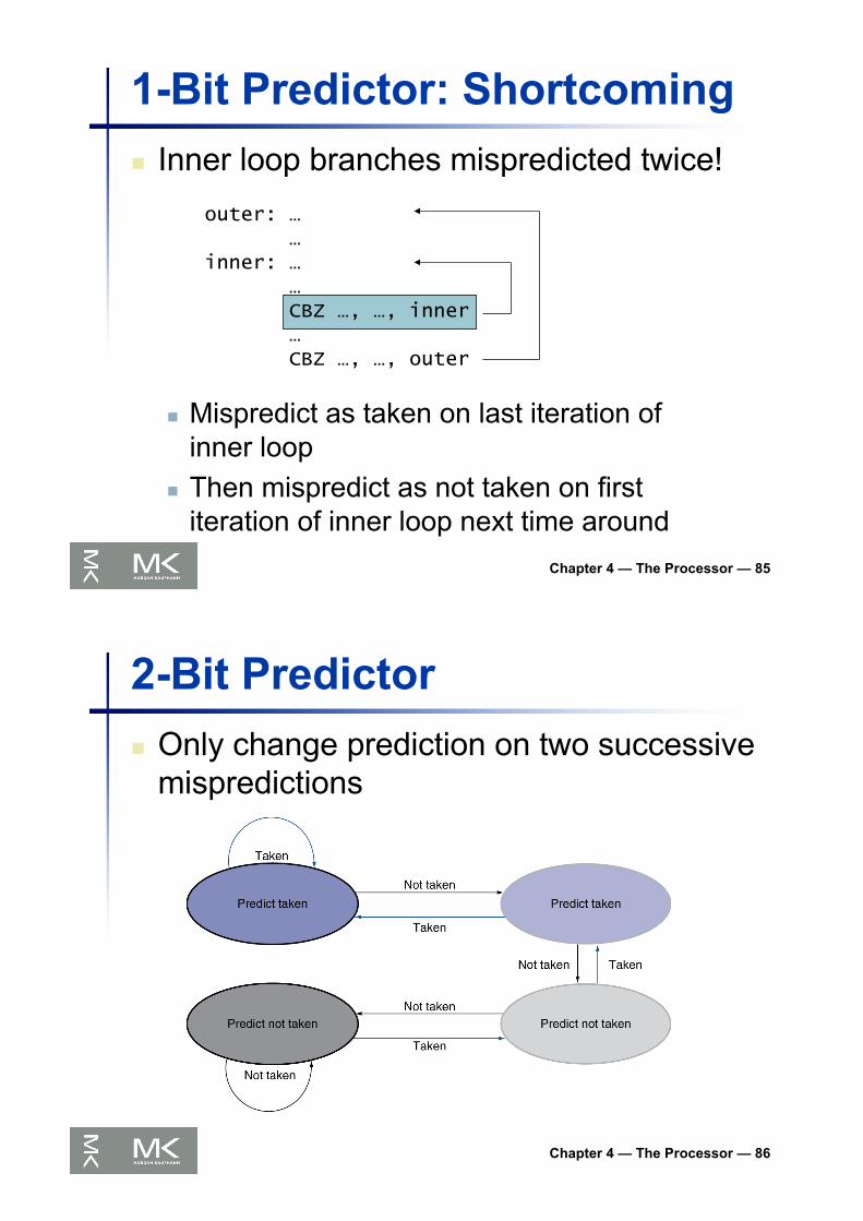
1-Bit Predictor: Shortcomingn Inner loop branches mispredicted twice!
outer: ……
inner: ……CBZ …, …, inner…CBZ …, …, outer
n Mispredict as taken on last iteration of inner loop
n Then mispredict as not taken on first iteration of inner loop next time around
Chapter 4 — The Processor — 86
2-Bit Predictorn Only change prediction on two successive
mispredictions

Chapter 4 — The Processor — 87
Calculating the Branch Targetn Even with predictor, still need to calculate
the target addressn 1-cycle penalty for a taken branch
n Branch target buffern Cache of target addressesn Indexed by PC when instruction fetched
n If hit and instruction is branch predicted taken, can fetch target immediately
Chapter 4 — The Processor — 88
Exceptions and Interruptsn “Unexpected” events requiring change
in flow of controln Different ISAs use the terms differently
n Exceptionn Arises within the CPU
n e.g., undefined opcode, overflow, syscall, …
n Interruptn From an external I/O controller
n Dealing with them without sacrificing performance is hard
§4.9 Exceptions

Chapter 4 — The Processor — 89
Handling Exceptionsn Save PC of offending (or interrupted) instruction
n In LEGv8: Exception Link Register (ELR)
n Save indication of the problemn In LEGv8: Exception Syndrome Rregister (ESR)n We’ll assume 1-bit
n 0 for undefined opcode, 1 for overflow
Chapter 4 — The Processor — 90
An Alternate Mechanismn Vectored Interrupts
n Handler address determined by the causen Exception vector address to be added to a
vector table base register:n Unknown Reason: 00 0000two
n Overflow: 10 1100two
n …: 11 1111two
n Instructions eithern Deal with the interrupt, orn Jump to real handler

Chapter 4 — The Processor — 91
Handler Actionsn Read cause, and transfer to relevant
handlern Determine action requiredn If restartable
n Take corrective actionn use EPC to return to program
n Otherwisen Terminate programn Report error using EPC, cause, …
Chapter 4 — The Processor — 92
Exceptions in a Pipelinen Another form of control hazardn Consider overflow on add in EX stage
ADD X1, X2, X1
n Prevent X1 from being clobberedn Complete previous instructionsn Flush add and subsequent instructionsn Set ESR and ELR register valuesn Transfer control to handler
n Similar to mispredicted branchn Use much of the same hardware

Chapter 4 — The Processor — 93
Pipeline with Exceptions
Chapter 4 — The Processor — 94
Exception Propertiesn Restartable exceptions
n Pipeline can flush the instructionn Handler executes, then returns to the
instructionn Refetched and executed from scratch
n PC saved in ELR registern Identifies causing instructionn Actually PC + 4 is saved
n Handler must adjust

Chapter 4 — The Processor — 95
Exception Examplen Exception on ADD in
40 SUB X11, X2, X444 AND X12, X2, X548 ORR X13, X2, X64C ADD X1, X2, X150 SUB X15, X6, X754 LDUR X16, [X7,#100]…
n Handler80000180 STUR X26, [X0,#1000]80000184 STUR X27, [X0,#1008]…
Chapter 4 — The Processor — 96
Exception Example
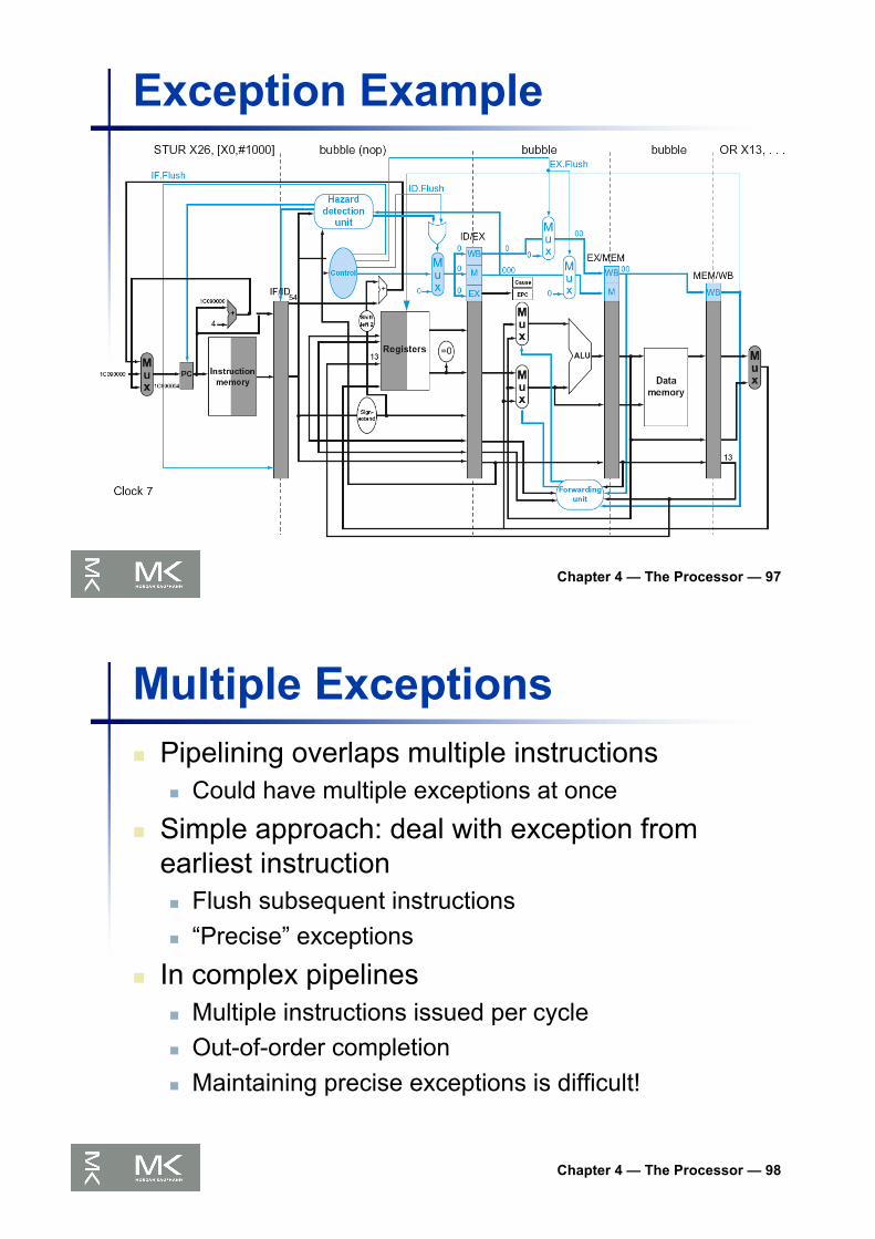
Chapter 4 — The Processor — 97
Exception Example
Chapter 4 — The Processor — 98
Multiple Exceptionsn Pipelining overlaps multiple instructions
n Could have multiple exceptions at once
n Simple approach: deal with exception from earliest instructionn Flush subsequent instructionsn “Precise” exceptions
n In complex pipelinesn Multiple instructions issued per cyclen Out-of-order completionn Maintaining precise exceptions is difficult!

Chapter 4 — The Processor — 99
Imprecise Exceptionsn Just stop pipeline and save state
n Including exception cause(s)
n Let the handler work outn Which instruction(s) had exceptionsn Which to complete or flush
n May require “manual” completion
n Simplifies hardware, but more complex handler software
n Not feasible for complex multiple-issueout-of-order pipelines
Chapter 4 — The Processor — 100
Instruction-Level Parallelism (ILP)n Pipelining: executing multiple instructions in
paralleln To increase ILP
n Deeper pipelinen Less work per stage Þ shorter clock cycle
n Multiple issuen Replicate pipeline stages Þ multiple pipelinesn Start multiple instructions per clock cyclen CPI < 1, so use Instructions Per Cycle (IPC)n E.g., 4GHz 4-way multiple-issue
n 16 BIPS, peak CPI = 0.25, peak IPC = 4n But dependencies reduce this in practice
§4.10 Parallelism
via Instructions
Chapter 4 — The Processor — 101
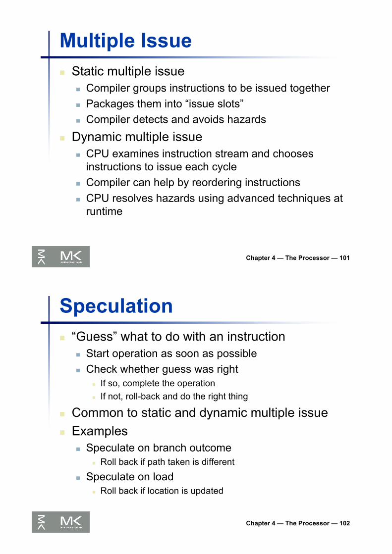
Multiple Issuen Static multiple issue
n Compiler groups instructions to be issued togethern Packages them into “issue slots”n Compiler detects and avoids hazards
n Dynamic multiple issuen CPU examines instruction stream and chooses
instructions to issue each cyclen Compiler can help by reordering instructionsn CPU resolves hazards using advanced techniques at
runtime
Chapter 4 — The Processor — 102
Speculationn “Guess” what to do with an instruction
n Start operation as soon as possiblen Check whether guess was right
n If so, complete the operationn If not, roll-back and do the right thing
n Common to static and dynamic multiple issuen Examples
n Speculate on branch outcomen Roll back if path taken is different
n Speculate on loadn Roll back if location is updated

Chapter 4 — The Processor — 103
Compiler/Hardware Speculationn Compiler can reorder instructions
n e.g., move load before branchn Can include “fix-up” instructions to recover
from incorrect guess
n Hardware can look ahead for instructions to executen Buffer results until it determines they are
actually neededn Flush buffers on incorrect speculation
Chapter 4 — The Processor — 104
Speculation and Exceptionsn What if exception occurs on a
speculatively executed instruction?n e.g., speculative load before null-pointer
checkn Static speculation
n Can add ISA support for deferring exceptionsn Dynamic speculation
n Can buffer exceptions until instruction completion (which may not occur)
Chapter 4 — The Processor — 105
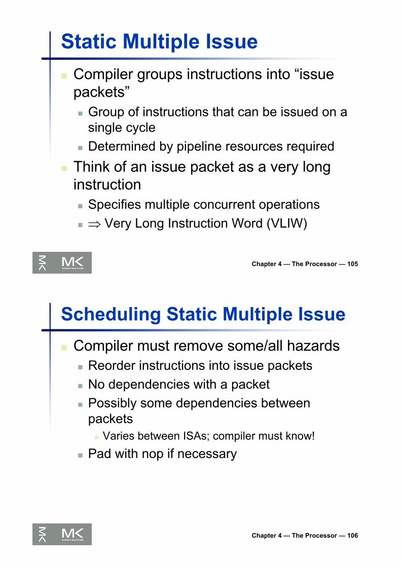
Static Multiple Issuen Compiler groups instructions into “issue
packets”n Group of instructions that can be issued on a
single cyclen Determined by pipeline resources required
n Think of an issue packet as a very long instructionn Specifies multiple concurrent operationsn Þ Very Long Instruction Word (VLIW)
Chapter 4 — The Processor — 106
Scheduling Static Multiple Issuen Compiler must remove some/all hazards
n Reorder instructions into issue packetsn No dependencies with a packetn Possibly some dependencies between
packetsn Varies between ISAs; compiler must know!
n Pad with nop if necessary

Chapter 4 — The Processor — 107
LEGv8 with Static Dual Issuen Two-issue packets
n One ALU/branch instructionn One load/store instructionn 64-bit aligned
n ALU/branch, then load/storen Pad an unused instruction with nop
Address Instruction type Pipeline Stages
n ALU/branch IF ID EX MEM WB
n + 4 Load/store IF ID EX MEM WB
n + 8 ALU/branch IF ID EX MEM WB
n + 12 Load/store IF ID EX MEM WB
n + 16 ALU/branch IF ID EX MEM WB
n + 20 Load/store IF ID EX MEM WB
Chapter 4 — The Processor — 108
LEGv8 with Static Dual Issue

Chapter 4 — The Processor — 109
Hazards in the Dual-Issue LEGv8n More instructions executing in paralleln EX data hazard
n Forwarding avoided stalls with single-issuen Now can’t use ALU result in load/store in same packet
n ADD X0, X0, X1LDUR X2, [X0,#0]
n Split into two packets, effectively a stall
n Load-use hazardn Still one cycle use latency, but now two instructions
n More aggressive scheduling required
Chapter 4 — The Processor — 110
Scheduling Examplen Schedule this for dual-issue LEGv8
Loop: LDUR X0, [X20,#0] // X0=array elementADD X0, X0,X21 // add scalar in X21STUR X0, [X20,#0] // store resultSUBI X20, X20,#4 // decrement pointerCMP X20, X22 // branch $s1!=0BGT Loop
ALU/branch Load/store cycle
Loop: nop LDUR X0, [X20,#0] 1
SUBI X20, X20,#4 nop 2
ADD X0, X0,X21 nop 3
CMP X20, X22 sw $t0, 4($s1) 4
BGT Loop STUR X0, [X20,#0] 5
n IPC = 7/6 = 1.17 (c.f. peak IPC = 2)

Chapter 4 — The Processor — 111
Loop Unrollingn Replicate loop body to expose more
parallelismn Reduces loop-control overhead
n Use different registers per replicationn Called “register renaming”n Avoid loop-carried “anti-dependencies”
n Store followed by a load of the same registern Aka “name dependence”
n Reuse of a register name
Chapter 4 — The Processor — 112
Loop Unrolling Example
n IPC = 15/8 = 1.875n Closer to 2, but at cost of registers and code size
ALU/branch Load/store cycle
Loop: SUBI X20, X20,#32 LDUR X0, [X20,#0] 1
nop LDUR X1, [X20,#24] 2
ADD X0, X0, X21 LDUR X2, [X20,#16] 3
ADD X1, X1, X21 LDUR X3, [X20,#8] 4
ADD X2, X2, X21 STUR X0, [X20,#32] 5
ADD X3, X3, X21 sw X1, [X20,#24] 6
CMP X20,X22 sw X2, [X20,#16] 7
BGT Loop sw X3, [X20,#8] 8

Chapter 4 — The Processor — 113
Dynamic Multiple Issuen “Superscalar” processorsn CPU decides whether to issue 0, 1, 2, …
each cyclen Avoiding structural and data hazards
n Avoids the need for compiler schedulingn Though it may still helpn Code semantics ensured by the CPU
Chapter 4 — The Processor — 114
Dynamic Pipeline Schedulingn Allow the CPU to execute instructions out
of order to avoid stallsn But commit result to registers in order
n ExampleLDUR X0, [X21,#20]ADD X1, X0, X2SUB X23,X23,X3ANDI X5, X23,#20
n Can start sub while ADD is waiting for LDUI
Chapter 4 — The Processor — 115
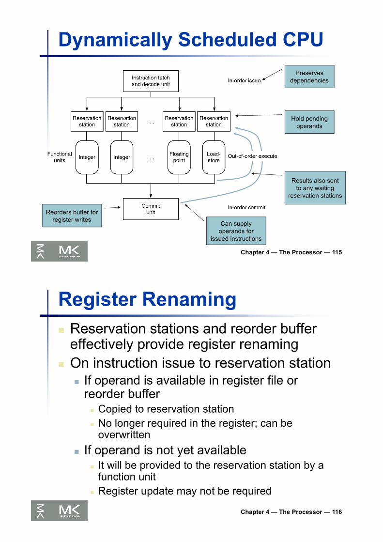
Dynamically Scheduled CPU
Results also sent to any waiting
reservation stations
Reorders buffer for register writes
Can supply operands for
issued instructions
Preserves dependencies
Hold pending operands
Chapter 4 — The Processor — 116
Register Renamingn Reservation stations and reorder buffer
effectively provide register renamingn On instruction issue to reservation station
n If operand is available in register file or reorder buffer
n Copied to reservation stationn No longer required in the register; can be
overwrittenn If operand is not yet available
n It will be provided to the reservation station by a function unit
n Register update may not be required
Chapter 4 — The Processor — 117
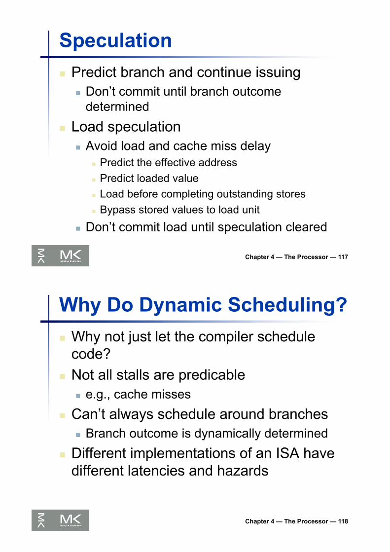
Speculationn Predict branch and continue issuing
n Don’t commit until branch outcome determined
n Load speculationn Avoid load and cache miss delay
n Predict the effective addressn Predict loaded valuen Load before completing outstanding storesn Bypass stored values to load unit
n Don’t commit load until speculation cleared
Chapter 4 — The Processor — 118
Why Do Dynamic Scheduling?n Why not just let the compiler schedule
code?n Not all stalls are predicable
n e.g., cache misses
n Can’t always schedule around branchesn Branch outcome is dynamically determined
n Different implementations of an ISA have different latencies and hazards
Chapter 4 — The Processor — 119
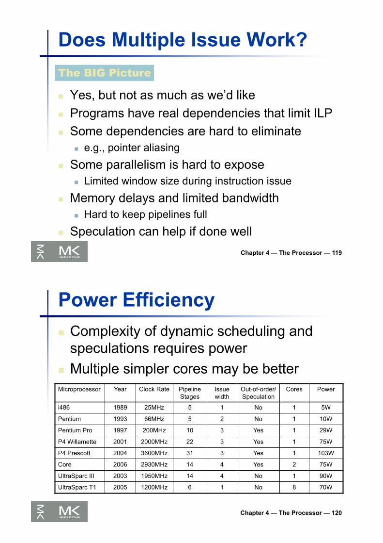
Does Multiple Issue Work?
n Yes, but not as much as we’d liken Programs have real dependencies that limit ILPn Some dependencies are hard to eliminate
n e.g., pointer aliasing
n Some parallelism is hard to exposen Limited window size during instruction issue
n Memory delays and limited bandwidthn Hard to keep pipelines full
n Speculation can help if done well
The BIG Picture
Chapter 4 — The Processor — 120
Power Efficiencyn Complexity of dynamic scheduling and
speculations requires powern Multiple simpler cores may be betterMicroprocessor Year Clock Rate Pipeline
StagesIssue width
Out-of-order/ Speculation
Cores Power
i486 1989 25MHz 5 1 No 1 5W
Pentium 1993 66MHz 5 2 No 1 10W
Pentium Pro 1997 200MHz 10 3 Yes 1 29W
P4 Willamette 2001 2000MHz 22 3 Yes 1 75W
P4 Prescott 2004 3600MHz 31 3 Yes 1 103W
Core 2006 2930MHz 14 4 Yes 2 75W
UltraSparc III 2003 1950MHz 14 4 No 1 90W
UltraSparc T1 2005 1200MHz 6 1 No 8 70W

Cortex A53 and Intel i7Processor ARM A53 Intel Core i7 920
Market Personal Mobile Device Server, cloud
Thermal design power 100 milliWatts(1 core @ 1 GHz)
130 Watts
Clock rate 1.5 GHz 2.66 GHz
Cores/Chip 4 (configurable) 4
Floating point? Yes Yes
Multiple issue? Dynamic Dynamic
Peak instructions/clock cycle 2 4
Pipeline stages 8 14
Pipeline schedule Static in-order Dynamic out-of-order with speculation
Branch prediction Hybrid 2-level
1st level caches/core 16-64 KiB I, 16-64 KiB D 32 KiB I, 32 KiB D
2nd level caches/core 128-2048 KiB 256 KiB (per core)
3rd level caches (shared) (platform dependent) 2-8 MB
Chapter 4 — The Processor — 121
§4.11 Real S
tuff: The AR
M C
ortex-A8 and Intel C
ore i7 Pipelines
ARM Cortex-A53 Pipeline
Chapter 4 — The Processor — 122

ARM Cortex-A53 Performance
Chapter 4 — The Processor — 123
Core i7 Pipeline
Chapter 4 — The Processor — 124

Core i7 Performance
Chapter 4 — The Processor — 125
Matrix Multiplyn Unrolled C code1 #include <x86intrin.h>2 #define UNROLL (4)34 void dgemm (int n, double* A, double* B, double* C)5 {6 for ( int i = 0; i < n; i+=UNROLL*4 )7 for ( int j = 0; j < n; j++ ) {8 __m256d c[4];9 for ( int x = 0; x < UNROLL; x++ )10 c[x] = _mm256_load_pd(C+i+x*4+j*n);1112 for( int k = 0; k < n; k++ )13 {14 __m256d b = _mm256_broadcast_sd(B+k+j*n);15 for (int x = 0; x < UNROLL; x++)16 c[x] = _mm256_add_pd(c[x],17 _mm256_mul_pd(_mm256_load_pd(A+n*k+x*4+i), b));18 }1920 for ( int x = 0; x < UNROLL; x++ )21 _mm256_store_pd(C+i+x*4+j*n, c[x]);22 }23 }
Chapter 4 — The Processor — 126
§4.12 Instruction-Level Parallelism
and Matrix M
ultiply

Matrix Multiplyn Assembly code:1 vmovapd (%r11),%ymm4 # Load 4 elements of C into %ymm42 mov %rbx,%rax # register %rax = %rbx3 xor %ecx,%ecx # register %ecx = 04 vmovapd 0x20(%r11),%ymm3 # Load 4 elements of C into %ymm35 vmovapd 0x40(%r11),%ymm2 # Load 4 elements of C into %ymm26 vmovapd 0x60(%r11),%ymm1 # Load 4 elements of C into %ymm17 vbroadcastsd (%rcx,%r9,1),%ymm0 # Make 4 copies of B element8 add $0x8,%rcx # register %rcx = %rcx + 89 vmulpd (%rax),%ymm0,%ymm5 # Parallel mul %ymm1,4 A elements10 vaddpd %ymm5,%ymm4,%ymm4 # Parallel add %ymm5, %ymm411 vmulpd 0x20(%rax),%ymm0,%ymm5 # Parallel mul %ymm1,4 A elements12 vaddpd %ymm5,%ymm3,%ymm3 # Parallel add %ymm5, %ymm313 vmulpd 0x40(%rax),%ymm0,%ymm5 # Parallel mul %ymm1,4 A elements14 vmulpd 0x60(%rax),%ymm0,%ymm0 # Parallel mul %ymm1,4 A elements15 add %r8,%rax # register %rax = %rax + %r816 cmp %r10,%rcx # compare %r8 to %rax17 vaddpd %ymm5,%ymm2,%ymm2 # Parallel add %ymm5, %ymm218 vaddpd %ymm0,%ymm1,%ymm1 # Parallel add %ymm0, %ymm119 jne 68 <dgemm+0x68> # jump if not %r8 != %rax20 add $0x1,%esi # register % esi = % esi + 121 vmovapd %ymm4,(%r11) # Store %ymm4 into 4 C elements22 vmovapd %ymm3,0x20(%r11) # Store %ymm3 into 4 C elements23 vmovapd %ymm2,0x40(%r11) # Store %ymm2 into 4 C elements24 vmovapd %ymm1,0x60(%r11) # Store %ymm1 into 4 C elements
Chapter 4 — The Processor — 127
§4.12 Instruction-Level Parallelism
and Matrix M
ultiply
Performance Impact
Chapter 4 — The Processor — 128

Chapter 4 — The Processor — 129
Fallaciesn Pipelining is easy (!)
n The basic idea is easyn The devil is in the details
n e.g., detecting data hazards
n Pipelining is independent of technologyn So why haven’t we always done pipelining?n More transistors make more advanced techniques
feasiblen Pipeline-related ISA design needs to take account of
technology trendsn e.g., predicated instructions
§4.14 Fallacies and Pitfalls
Chapter 4 — The Processor — 130
Pitfallsn Poor ISA design can make pipelining
hardern e.g., complex instruction sets (VAX, IA-32)
n Significant overhead to make pipelining workn IA-32 micro-op approach
n e.g., complex addressing modesn Register update side effects, memory indirection
n e.g., delayed branchesn Advanced pipelines have long delay slots
Chapter 4 — The Processor — 131
Concluding Remarksn ISA influences design of datapath and controln Datapath and control influence design of ISAn Pipelining improves instruction throughput
using parallelismn More instructions completed per secondn Latency for each instruction not reduced
n Hazards: structural, data, controln Multiple issue and dynamic scheduling (ILP)
n Dependencies limit achievable parallelismn Complexity leads to the power wall
§4.14 Concluding R
emarks