chapter eleven rev08 - electrical engineeringanders/courses/ee481lf07/nearspacecraft/nearspac… ·...
TRANSCRIPT

© Parallax Inc. Rev 1.0 2006
CHAPTER ELEVEN
Chase And Recovery "Do you chase UFO's?"
"No, I know what I chase." - Conversation with a stranger at a gas station in Kansas
Chapter Objectives
1.0 The Chase............................................................................................................ 1 2.0 The Recovery ..................................................................................................... 25 Good To Know - An Introduction To Packet And APRS .................................................... 36 Near Space Humor - Top Six Chase Songs...................................................................... 38
1.0 The Chase Chasing balloons makes my Saturday a fantastic day. Being on a mission that most people will never experience. Using high tech equipment that really catches the eye. Feeling like I’m on a mission like the actors in the movie, Twister. It all adds up to a great day.
High tech equipment - Really catches the eye
1.1. The Chase Or Tracking Vehicle Two names are commonly heard for the cars that chase after the balloon, Chase vehicles and Tracking Vehicles. I suppose if the car carries an APRS tracker, then it is more properly called a Tracking Vehicle and if the car only carries communications equipment and depends on a Tracking Vehicle it is more properly called a Chase Vehicle. Take your pick or make up a new name. Most automobiles

Page 2 of 39 · Near Space Exploration with the BASIC Stamp by Paul Verhage
© Parallax Inc. Rev 1.0 2006
work well for near space chase. Any car capable of carrying an APRS tracker and/or communication equipment is suitable for a Near Space Tracking And Recovery vehicle. You'd be amazed at the 1984 Ford Escort the author took on many balloon chases. It’s amazing that gutless wonder didn't have a heart attack. There are times when a car designed for off-road driving is better. A Jeep of other SUV (or should that be UAV for, Urban Assault Vehicle?) is a good match at the end of the chase where the roads may become non-existent. In the author’s experience, the Midwest has descent roads very close to the recovery site, but in mountainous states like Idaho it’s a bit more problematical. There aren't many paved roads on the tops of 12,000-foot mountains.
Chase Vehicle Interior
1.1.1. Mobile APRS Setup The next four subsections will help you set up a mobile Automatic Packet Reporting System (APRS) tracker for your near space tracking and recovery vehicle. Your local APRS community is usually happy to help also. Before launching and chasing a balloon, there must be at least one Tracking Vehicle. For added insurance, at least two cars should be tracking. Multiple trackers prevent one tracking failure from stranding the Chase Team and losing the near spacecraft. Of course it even better if every car carries an APRS tracker, but this isn’t realistic. There are enough versions of APRS that any laptop can be used as a tracker. The quality of the maps depends on the capabilities of the laptop. There’s even a version of APRS for Palm Pilots. APRS functions by parsing text data received through the laptop’s comm port (at 1200 baud, N81) and displaying it on moving maps. Not only does APRS display graphical data, it can also send and receive text messages sent over packet radio. It is truly an amazing program. Along with the laptop, a terminal node controller (TNC) is required for APRS. The TNC connected to a laptop running APRS completes the following steps.
• Accepts text data from a PC or laptop • Breaks the text string into shorter packets (if the text is larger than one packet) • Adds the appropriate address headers to the packet • Creates a cyclical redundancy code (CRC) for each packet for error correction purposes • Keys the radio connected to the TNC • Converts the text packets into audio tones for transmission over the radio • Unkeys the radio

Chapter Eleven: Chase And Recovery · Page 3 of 39
© Parallax Inc. Rev 1.0 2006
Packets received over the radio go through the same process, but in reverse order and without having to key and unkey the radio. A PC (usually a laptop) with a TNC and radio are required to operate APRS. However a GPS receiver connected to the laptop makes APRS an even more powerful tool for the Chase Team by displaying their position along with the near spacecraft’s position on a moving map. Any standard GPS receiver is suitable for APRS (the author would hesitate using an older model GPS receiver until after it is determined that the GPS receiver follows the NMEA 0183 standard. Don't let a balloon chase be a tracker’s first exposure to using APRS. Give a new tracker a chance to practice using APRS by letting them track a functioning near spacecraft carried around in a car or truck. At a minimum a tracker should know APRS well enough to do the following tasks.
• Start and stop logging TNC data • Determine the near spacecraft's position in relationship to the landmarks • Zoom the display in and out • Estimate distances on the display
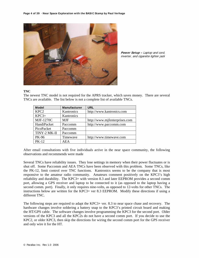
1.1.2. Setting Up A Mobile APRS Tracker The next eight items are suggested for your APRS Tracker. For additional help, contact your local APRS community, they will be happy to show you the ropes and help you set up a tracker. This section assumes the tracking and recovery vehicle carries a laptop to run APRS. There are other ways to run APRS that uses a Palm Pilot or Kenwood Data Radio. These last methods are not as useful as a laptop because of their limited mapping capability, but they do complement a laptop APRS tracker. Laptop The newer the model laptop used, the more powerful the tracking program that can be loaded on it. If your TNC does not include a second comm. port, the PC should have one (possibly through a PC card). With the bouncing around inside a chase vehicle on a mission, it is very difficult (read, almost impossible) for the Navigator to use the built-in mouse cursor on the laptop. So instead of relying on the installed mouse, use a larger external mouse and give the Navigator a mouse pad and solid base. Power A good quality inverter connected to the cigarette lighter (the only good use of a cigarette lighter in my not so humble opinion) should be the primary power source for the laptop. The laptop’s batteries should be used to provide power when the car is shut off. Use an inverter because most laptops cannot be connected directly into an automobile’s 12-volt system. Even if the laptop uses a 12-volt wall transformer, the voltage spikes present in the electrical system plays havoc with the laptop and sooner or later will damage the laptop. Wal-Mart carries a line of inexpensive 12-volt inverters. Check the power requirements of the laptop’s wall transformer before purchasing a 12-volt inverter. All inverters list the amount of current they can supply, so make sure this number is greater than the laptop’s requirement. Another option for external power is to carry a separate 12-volt battery for the laptop. In this case, use a deep cycle battery, like a marine battery. The deep cycle battery design allows them to be deeply discharged before being recharged. Deep discharging a standard automobile battery reduces the battery’s lifetime. Mount the separate battery inside a marine battery case and place it on the car floor where it cannot tip over. In addition, consider adding a voltmeter and ammeter to the battery to monitor its voltage and discharge rate during the chase
Page 4 of 39 · Near Space Exploration with the BASIC Stamp by Paul Verhage
© Parallax Inc. Rev 1.0 2006
Power Setup – Laptop and cord, inverter, and cigarette lighter jack
TNC The newest TNC model is not required for the APRS tracker, which saves money. There are several TNCs are available. The list below is not a complete list of available TNCs.
Model Manufacturer URL KPC2 Kantronics http://www.kantronics.com KPC3+ Kantronics MJF-1270C MJF http://www.mjfenterprises.com HandiPacket Paccomm http://www.paccomm.com PicoPacket Paccomm TINY-2 MK-II Paccomm PK-96 Timewave http://www.timewave.com PK-12 AEA
After email consultations with five individuals active in the near space community, the following observations and recommends were made Several TNCs have reliability issues. They lose settings in memory when their power fluctuates or is shut off. Some Paccomm and AEA TNCs have been observed with this problem. Some TNCs, like the PK-12, limit control over TNC functions. Kantronics seems to be the company that is most responsive to the amateur radio community. Amateurs comment positively on the KPC3’s high reliability and durability. The KPC3+ with version 8.3 and later EEPROM provides a second comm port, allowing a GPS receiver and laptop to be connected to it (as opposed to the laptop having a second comm. port). Finally, it only requires nine-volts, as opposed to 12-volts for other TNCs. The instructions below are written for the KPC3+ ver 8.3 EEPROM. Modify these directions if using a different TNC. The following steps are required to adapt the KPC3+ ver. 8.3 to near space chase and recovery. The hardware changes involve soldering a battery snap to the KPC3’s printed circuit board and making the HT/GPS cable. The software changes involve programming the KPC3 for the second port. Older versions of the KPC3 and all the KPC2s do not have a second comm port. If you decide to use the KPC2, or older KPC3, then skip the directions for wiring the second comm port for the GPS receiver and only wire it for the HT.

Chapter Eleven: Chase And Recovery · Page 5 of 39
© Parallax Inc. Rev 1.0 2006
Hardware Changes Battery Snap The KPC 3+ does not have a factory installed battery snap. You must add one. List of Materials 9-volt battery snap (use the heavy-duty battery snap from Radio Shack, 270-324) Procedure
√ Open the KPC 3+ case √ Locate the battery snap pads
Look in the KPC3+ Manual for directions. Instructions are located under the section, Installing Your KPC3+ in subsection, Internal Power, from a Battery. Currently the nine-volt battery snap is soldered to pads located in the back left of the TNC’s PCB.
√ Solder the red 9V battery snap lead to the + pad and the black lead to the - pad √ Glue a sheet of foam rubber onto the inside of the lid, over the battery
This places pressure on the battery once you bolt the lid back onto the TNC. The pressure keeps the battery from bouncing around inside the case, possibly causing mischief.
Inside of KPC 3+ - Note the solder pads for the battery snap, circled at upper left.
HT and GPS Cable The Radio Port will be wired for the HT and GPS Receiver. List of Components
• Six lengths of #22 or #24 gauge stranded wire (about 12” long) o Use three different colors of wires, with two black wires for the ground connections
• Capacitor (see KPC3 directions for proper capacitor value for your HT) • Resistor (see KPC3 directions for proper resistor value for your HT) • 1/8” male phono jack

Page 6 of 39 · Near Space Exploration with the BASIC Stamp by Paul Verhage
© Parallax Inc. Rev 1.0 2006
• 3/16” male phono jack • Two male D-subminiature connectors (DB-9) • Female D-subminiature connectors (DB-9) • Three ½” lengths of ¼” diameter heat shrink • Two ¾” lengths of ¼” diameter heat shrink • Two DB-9 plastic housing kits
Procedure To Make The HT Cable
Connection Diagram for HT Cable
√ Strip back ¼” of insulation from one end of each wire √ Solder the wires to the solder cups of one of the male DB-9 connectors as listed below
GND: Pin 6 Use both black colored wires TX: Pin 1 PTT: Pin 3 NMEA Input: Pin 2 Audio Input: Pin 5
√ Slide a length of heat shrink on each wire and cover the exposed solder connection √ Cut both leads of the resistor and capacitor to a length of ½” √ Solder one lead of the capacitor and resistor to the tip connection of the 3/16” phono jack √ Tin the other lead of the resistor and capacitor √ Strip two inches of insulation from the other end of one of the black GND wires √ Connect and solder the open end of the GND wire to the base of the 1/8” phono jack √ Slide a ¾” length of heat shrink over the PTT and TX wires √ Plug both jacks into the HT and the DB-9 connector into the TNC √ Separate the TNC from the HT, stretching the GND wire out √ Lay the TX wire up to the base of the capacitor and cut and strip the wire to length √ Lay the PTT wire up to the base of the resistor and cut and strip the wire to length √ Tin the leads of the PTT and TX wires √ Solder the wires to their respective components √ Note there is no need to twist the wires and leads together, just let the solder flow around the
wires √ Solder the Audio Input wire to the tip of the 1/8” phono jack √ Slide the heat shrink tubing up and cover the exposed soldered connections

Chapter Eleven: Chase And Recovery · Page 7 of 39
© Parallax Inc. Rev 1.0 2006
√ Use hot glue to cover the solder cups of the DB-9 connector Do the next steps in quick succession so that glue doesn’t get cold before closing the housing
√ Place the bolts into the DB-9 housing √ Pour some hot glue into the bottom half of the DB-9 housing √ Place the DB-9 connector and it’s wires into the housing √ Pour some hot glue into the top half of the DB-9 housing √ Close and bolt the housing halves together √ Back fill the housing with hot glue √ Label the housing as Radio Port
The GPS Cable (Skip to Close DB-9 Housing step if not using a version 8.3 or later EEPROM)
√ Cut three #24 AWG stranded wires to a length of 12” o use a meaningful color scheme, the ground wire should be black
√ Strip ¼” of insulation from the ends of the wires √ Get the second DB-9 connector and housing ready √ Separate the NMEA Input and second Ground wire from the other wires in the first DB-9
connector √ Slide ¼” length of heat shrink on both wires √ Solder the GND wire (black) to pin 5 of the male DB-9 connector √ Solder the NMEA Input and a second wire to pin 2 of the male DB-9 connector (TX from
the GPS) √ Solder the remaining wire to pin 3 of the male DB-9 connector (RX from the GPS) √ Slide the heat shrink over the solder connections and shrink √ Use hot glue to cover the solder cups of the DB-9 connector
Do the next steps in quick succession so that glue doesn’t get cold before closing the housing Close The DB-9 Housing
√ Place the bolts into the DB-9 housing √ Pour some hot glue into the bottom half of the DB-9 housing √ Place the DB-9 connector and it’s wires into the housing √ Pour some hot glue into the top half of the DB-9 housing √ Close and bolt the housing halves together √ Back fill the housing with hot glue √ Label the housing as GPS

Page 8 of 39 · Near Space Exploration with the BASIC Stamp by Paul Verhage
© Parallax Inc. Rev 1.0 2006
Completed GPS cable
Laptop Comm Port Use a standard DB-25 to DB-9 serial cable to connect the TNC to the laptop. Software Changes The following commands instruct the KPC 3+ ver 8.3 TNC to operate as an APRS tracker. INT TERMINAL GPSPORT 4800 NORMAL CHECKSUM BT “Your message about the chase, or being a part of it” Note: Precede text with a right caret (>) BLT 1 00:05:00 GPSHEAD 1 $GPRMC HEADERLINE OFF CD SOFTWARE LTP 1 GPSLV VIA RELAY,WIDE2-2 LTP1 notes GPSLV under the LTP1 setting indicates the icon to display under APRS for your chase vehicle. A few of the options are as follows GPSLV Van Symbol GPSMV Car Symbol GPSLK Truck Symbol Check with your local APRS community about the RELAY and WIDE setting. Not every location accepts the same settings. GPS Receiver A GPS receiver is not strictly needed, but it is so useful that there’s no reason not to carry one during chase. Any GPS receiver outputting NMEA 0183 standard signals (this should be all commercially available current GPS receivers) works with APRS. There are two popular locations for the GPS receiver, on the dash and on the roof of the car. There are benefits for using each type of GPS receiver. The roof mounted GPS receiver has more consistent satellite reception and is normally desired over a dash-mounted position where satellite reception depends on which way the car is pointed. The roof-mounted GPS receiver costs more than the basic Garmin Etrex (a handheld GPS

Chapter Eleven: Chase And Recovery · Page 9 of 39
© Parallax Inc. Rev 1.0 2006
receiver without a magnetic face). A roof-mounted GPS receiver needs a connection to the car’s cigarette lighter for power whereas the handheld Etrex uses internal batteries (two AA cells). With two fresh alkaline cells, the Etrex operates for 22 continuous hours, almost enough time for a year’s worth of chases. Also, with internal batteries, the clutter of wires inside the chase vehicle is reduced. It’s left as an exercise for the reader to determine how useful it is to have fewer cables snaking their way around the dash. A roof-mounted GPS receiver comes with a serial and power cable already attached to it. However, hand-held models require the purchase of a serial cable. Use the Pfranc serial cables for the handheld models to save money over the manufacturer’s serial cables. The serial cable for the roof-mounted GPS receiver is another cable snaking its way around the car. The Etrex is positioned near the laptop where its serial cable is out of the way. A good place to order some GPS receivers is TAPR, which helps to support amateur radio. Outside of TAPR, 4X4 sells affordable Etrex GPS receivers. There is a hybrid option, using a dash mounted GPS receiver with an external antenna. GPS receivers like the Garmin GPS 48 allows for an external antenna, but the Garmin Etrex does not. The GPS is connected to a second comm port, either on the TNC or the laptop. There are no modifications to make to the GPS in software. Hardware changes only have to be made to roof-mounted GPS receivers with serial cables that do not terminate in DB-9 connectors. Terminating the Garmin GPS35 These directions are for Garmin GPS35 receivers that do not terminate in a DB-9 connector (the end of the cable is bare). The directions are modifications to the directions in Chapter Four, Section One. Materials
• Female DB-9 connector kit with solder cups • DB-9 plastic housing kit • Short length of #22 AWG wire • A three or four foot length of two-conductor stranded cable for GPS power • Note: The final length depends on the placement of the laptop relative to the cigarette lighter • One cigarette lighter power connector • Sort lengths of heat shrink tubing with large enough diameter to cover the solder cups of the
DB-9 • Hot glue
Procedure Strip back two inches of the outer jacket of the GPS35 cable. You’ll see about ten wires inside the cable. The wires needed are the following,
Wire Color Signal Blue RXD1 White TXD1 Black GND Red Vin
√ Strip ½” of insulation from one end of the wires in the power cable √ Strip back ¼” of insulation from the Blue, White, Black, and Red wires of the GPS35 cable √ Slide a short length of heat shrink on the Blue and White wires √ Solder the White wire to pin #3 solder cup of the DB-9 connector √ Solder the Blue wire to pin #2 solder cup of the DB-9 connector √ Slide a short length of heat shrink over the end of the ground wire of the power cable

Page 10 of 39 · Near Space Exploration with the BASIC Stamp by Paul Verhage
© Parallax Inc. Rev 1.0 2006
√ Strip ¼” of insulation from the end of the short length of wire (ground extension) √ Twist the power wire to the Black GPS35 wire and the short length of wire √ Measure the length of the ground extension wire needed to reach pin #5 of the DB-9
connector √ Cut the ground extension to length and strip ¼” of insulation from the end √ Solder the ground extension wire to pin #5 solder cup of the DB-9 connector √ Slide a short length of heat shrink over the end of the positive wire of the power cable √ Solder the 22 AWG wire to the Red GPS35 wire √ Slide the heat shrink over all soldered connections and shrink them √ Fold back the power cable so it will exit the DB-9 hood through the back end, where the data
cable enters √ Note: You may have to enlarge the hole slightly to get both the data and power cable
through the same hole √ Squirt some hot glue over the solder cups of the DB-9 √ Put a layer of hot glue in the bottom half of the DB-9 hood √ Place the DB-9 into the bottom half of the DB-9 hood, being careful not to ooze hot glue all
over the place √ Squirt some more hot glue over the top of the wires in the hood to fill in gaps √ Put a layer of hot glue in the top half of the DB-9 hood √ Close the top over the bottom half, being careful to wipe up any excess hot glue √ Bolt the halves together
√ Strip one inch of insulation from the exposed ends of the power cable √ Insert the free ends into the cigarette light power plug √ Note: Depending on the design of the power plug, this may require the wires to bolted or
crimped to metal contacts GPS Signal Strength Harry Muller (KC5TRB) of ORB in Oklahoma tested the quality of GPS signal with a Tripmate GPS receiver in several locations in his van. Condensed down, the test shows the following resultsA. Location Number of Satellites Average Signal to Noise Ratio (SNR) In The Open 10 36.3/99 Underneath A Fiberglass Roof 10 39.5/99 Six Inches Beneath Carpet, Wood, And Fiberglass Roof
10 38.0/99
From these results it can be seen the placing a GPS receiver beneath the fiberglass ceiling of a van does not attenuate signals enough to drop the number of Navstar satellites detected by the GPS receiver. Oddly enough, it seems to help. The increased SNR may be more affected by the reduction of outside interference rather than the attenuation of GPS signals. Radios (usually an HT) Almost any HT will work as part of an APRS Tracker as long as it supports an external antenna (this removes the Alinco DJ-S11 from consideration unless it is modified for external antenna). Most HTs have greater transmitter power when connected to the 12-volt battery of the chase vehicle than when it runs off its own internal battery. Rather than make a power cable, use the 12-volt cigarette lighter jack supplied with the HT (this assumes the HT is designed for 12-volt use and comes with a cigarette lighter adapter).

Chapter Eleven: Chase And Recovery · Page 11 of 39
© Parallax Inc. Rev 1.0 2006
Magmount Antenna An external magmount antenna for the HT is the only suitable antenna, as an internal antenna is blocked from most APRS transmissions. Where the antenna coax enters the car, a pass through is needed or else the wind whistles inside the car from the partially opened window. Window Pass-Through
Example of Window Pass-Through on Vehicle – Sign reads "STOP Emergency Exit Only"
Materials
• 3/8” thick plywoodB • #6-32 hardware • Wood construction glue • Spray paint • Laminated signC (if desired) •
Procedure

Page 12 of 39 · Near Space Exploration with the BASIC Stamp by Paul Verhage
© Parallax Inc. Rev 1.0 2006
Window Pass-Through Diagram
√ Measure the width of a car window the antenna cables are to pass through √ Cut two strips of plywood to measure the width of the window and three inches deep √ Cut a third strip of plywood to measure one inch deep and the length of the window √ Glue and clamp the wood together, sandwiching the narrow strip inside the two wider strips
and all pieces flush at the top √ Measure the diameter of the coax cables that must pass through the window √ At the top of the pass-through, cut and smooth notches in the wood for the coax cables √ Paint the pass-through √ Drill two holes in the pass-through for the bolts √ Note: Center the holes in the narrow inner piece of plywood and two inches from the sides (I
don’t trust the glue to hold-up, so I also add bolts) √ Bolt the glued plywood pieces together with the sign √ Note: The sign must be bolted to the inside face of the pass-through or else winds generated
while driving will eventually rip it off

Chapter Eleven: Chase And Recovery · Page 13 of 39
© Parallax Inc. Rev 1.0 2006
APRS +SA The letters in APRS + SA stands for Automatic Packet Reporting system, plus Street Atlas. There are many versions of APRS, including some that do not require Street Atlas. Other mapping programs can be used, including maps that you generate yourself. This book focuses on using APRS +SA because it has become something of a standard and because of its usefulness. All versions of APRS can be found at the Tucson Amateur Packet Radio (TAPR) website at http://www.tapr.org. Download and install the Shareware version on a PC or laptop. Street Atlas There are many versions of Street Atlas. Versions beginning with version four (and possibly earlier versions) are capable with APRS +SA. The newer versions have more complete road information. However, an older version still may be actuate enough for chase, which may save you money. Using A Monitor If laptop visibility is an issue (for example, when glare makes the laptop’s LCD screen unreadable), consider connecting a monitor to the laptop’s video port. Vans, with lots of space between the driver and passenger, are examples of cars where monitors can be used.
1.1.3. TVNSP Suggested APRS Setting These are the APRS setting most frequently used by the TVNSP Chase Team. Note that APRS is an evolving program. Settings and the names of the settings change from time to time, but this guide will get you through most of the hurdles. SETUP Menu Main Dropdown Menu Callsign: Enter your callsign Lat: Enter your latitude in decimal degrees

Page 14 of 39 · Near Space Exploration with the BASIC Stamp by Paul Verhage
© Parallax Inc. Rev 1.0 2006
Long: Enter your longitude in decimal degrees Registration: Enter your APRS registration number Note: If west of the Prime Meriden (like the US), the precede the longitude with a negative sign Optional, if not programmed in the TNC Symbol Button: Select symbol from the Primary Symbol Table Via: RELAY,WIDE3-3 TNC Configuration Select your TNC’s initialization settings Note: INITKAM works for KPC2 INITKPC works for KPC3 INITVHF for other TNCs Port 1 TNC Baud: Enter your TNC baud rate (normally 4800) Port: 1 Com1 Note: This is assuming your TNC is connected to COM Port 1. Mode: Pico Note: Ignore PORT 2 GPS if using the KPC3+ GPS Port Port 2 GPS Baud: 4800 Port: 2 Com2: (or 1 Com1: if using a HSP) Mode: NMEA Click the Smart button Click Enable Transmit TNC/TCPIP option Note: At least one chase vehicle should enable this feature, it lets Mission Control locate the position of the Chase Team Click Smart button Note: Accept the defaults to begin with Close Main Window SETUP Menu Lists Dropdown Menu Click the Only Track This List option Close Lists Window SETUP Menu Program Dropdown Menu Click SA4 (or your version of Street Atlas) option Click Turn Scrolling On After Menu Action On Position Page option Note: The above option is called Turn Pause Off After Menu Action On Position Page in older versions of APRS.
Chapter Eleven: Chase And Recovery · Page 15 of 39
© Parallax Inc. Rev 1.0 2006
Click the Position Page Update On New Positions Only option Fill information in Agent Character window to use a text-to-speech add-on like Peedy Close Setup Window COMMANDS Menu Map Dropdown Menu APRS Tab Click Include Track Lines option Click Bring SA To The Front On New Map option Click Include Callsigns option Click “Locate” Functions ignore Fixed Center option Click the OK button COMMANDS Clear Click Remove Lat/Long = 0 90 180 option COMMANDS Click Start Street Atlas option If using a Tripmate GPS receiver, then complete the following step COMMANDS TNC Commands Tripmate Select either ASTRAL To TNC Port Or ASTRAL To GPS Port Note: The Tripmate does not come with a power switch. If the Tripmate is connected to the KPC3+ GPS Port, then select ASTRAL To TNC Port. If the Tripmate is connected to the laptop, then select ASTRAL To GPS Port. Sending the text ASTRAL to the Tripmate over its comm port starts it.
1.1.4. Notes On TVNSP Suggested APRS Settings SETUP/Main FCC regulations require all amateur radio transmissions to identify themselves with a callsign at regular intervals. Every APRS packet that is transmitted with the callsign prefixed. The latitude and longitude is the initial location of the APRS station and is the position reported if the GPS is left off when APRS is started. A negative longitude is the standard for a west longitude as a positive longitude is the standard for east longitude. Many APRS stations in the US are displayed in the Asia because longitudes are not preceded with a negative symbol. SETUP/Main/Port 1 TNC and Port 2 GPS The most effective APRS stations appear to use two separate comm ports for the GPS and TNC as opposed to a hardware serial port (HSP). The HSP electronically switches one comm port between
Page 16 of 39 · Near Space Exploration with the BASIC Stamp by Paul Verhage
© Parallax Inc. Rev 1.0 2006
two serial devices. Note, the serial port for the GPS can be located on the KPC3+ TNC (version 8.3 EEPROM), rather than on the laptop. Currently, most packet traffic occurs at 1200 baud (although the technology for 9600 packet does existD) and NMEA compliant GPS receivers operate at 4800 baud. Setting the TNC mode to Pico, the GPS to NMEA and clicking the smart button activates smart beaconing. In smart beaconing, positions from the GPS are sent less frequently as long as there is no change in the speed and direction of the chase vehicle. When the speed or direction does change, an immediate position report is transmitted notifying Mission Control the Chase Team has changed directions. Smart beaconing reduces the amount of packet data required to specify the position of the Chase Team. When using Smart Beaconing, program the TNC to CLEAR the LT Buffers after each packet to avoid sending old position reports. SETUP/Main/TNC Configuration TNC configuration files are text files containing TNC commands for each particular TNC. When started, a PC running APRS puts the TNC into the proper setting by sending the commands in the TNC’s initialization file to the TNC. SETUP/Main/Via Note: Consult with your local APRS community. Some locations do not support RELAYing. A WIDE3-3 setting lets packets from the near spacecraft be relayed three times through digi-peaters. SETUP/Program Click the Turn Pause Off After Menu Action On Position Page (in older versions of APRS) or Turn Scrolling On After Menu Action On Position Page (in newer versions of APRS) prevents the position reports from scrolling down automatically as packet reports come in. Selecting to Position Page Update On New Positions Only prevents APRS from updating the map with every position report it receives (this includes position reports from stations other than the near spacecraft). If the map is updated every time someone reports a position, you’ll lose track of the near spacecraft. Several text to speech programs are available for APRS. Peedy is one popular one. Peedy is a parrot program that moves its beak when speaking the text it is receiving. Peedy also moves his head around between text packets. Text-to-speech agents are popular with the civvies that have never watched the tracking of a near spacecraft. Other Microsoft Agents include, Genie, Merlin, and Robie. They can be found at http://www.microscoft.com/msagent/ COMMANDS/Map/APRS Tab Track lines show the past location of the near spacecraft. Without track lines only the current location is seen, and without the context of a history (previous flight path). Bringing SA to the front keeps the Street Atlas map in the front window. If the map is not brought to then front, then the Chase Team must click to bring the map to where you can see it. Displaying the callsigns of tracked objects is optional, but useful when trying to identify chase vehicles. COMMANDS/Clear Removing Latitudes and Longitudes containing 0, 90, and 180 degrees prevents a bad GPS coordinate from sending the map to a location off the west coast of Africa. Bad coordinates can occur when a GPS loses its lock or when an APRS’ GPS has not been started. In which case, a latitude and longitude of zero degrees is sent.

Chapter Eleven: Chase And Recovery · Page 17 of 39
© Parallax Inc. Rev 1.0 2006
COMMANDS By selecting to start Street Atlas, APRS opens Street Atlas when you start APRS. There is no need to start both programs.
1.1.5. Chasing With APRS +SA Now that APRS +SA and Street Atlas are installed and configured, here are the directions for starting APRS for the near space chase. Start APRS, which also starts Street Atlas Click SETUP Click Lists Enter callsigns to be tracked in the Keep All Tracking Data column Click Maps Tab Click Select Maps button Click Maps in dropdown menu Click Map3: Map3 Click Maps Tab Click Select Maps button Click Maps in dropdown menu Click Map4: Map4 Click Track tab Click ENABLE TRACKING option Click Auto Map Update option Enter callsigns to track in the <Callsign window Or Double click callsigns to track in either the Stationary or Moving columns Now the stations selected are displayed on the SA map Click Position2 tab Right click on callsign of near spacecraft Click Turn ON Range/Bearing Update option Click My Location option Click File Click Start Logging TNC Data Enter name for log file in the window and click the Open button After recovery of the near spacecraft, stop logging TNC data Click File Click Stop Logging TNC Data
1.1.6. Chasing With Balloon Track Rick von Glahn (N0KKZ) of EOSS has done it again. His latest update to Balloon Track for Windows not only predicts the flight of a near spacecraft from winds aloft data, but also displays a wealth of information during the mission. Rick has written a manual for Balloon Track. The manual

Page 18 of 39 · Near Space Exploration with the BASIC Stamp by Paul Verhage
© Parallax Inc. Rev 1.0 2006
along with the program is available at the EOSS website, http://www.eoss.org. Select the Downloads option. Here are just three of many reasons to track near spacecraft with Balloon Track for Windows. Dash Board Balloon Track has a Dash Board window displaying such information as, altitude, course and speed of the near spacecraft, and bearing, range, and distance of the near spacecraft from the tracking vehicle. The questions asked most frequently after, “Where is the balloon?” are, “How high is the balloon?”, “Where is the balloon heading?”, and “How fast is the balloon moving?”. All this information is quickly accessible from Dash Board and not APRS, which is a more generic packet radio program and not fine tuned to the needs of amateur near space exploration like Balloon Track. To get to the Dash Board, do the following
√ Start Balloon Track for Windows √ Click on the Packet Data menu √ Select Packet Terminal from the drop down menu √ Click the Dash Board button
Flight Analysis Another useful window is the Flight Analysis window. Flight analysis much of the same data as found in the Dash Board, but also includes selectable graphs of flight characteristics over time like, Attitude, Ascent Rate, Speed, Range, Track, and Course. In addition, trends in vertical speed, horizontal speed, and course are also displayed. To get to the Flight Analysis, do the following
√ Start Balloon Track for Windows √ Click on Packet Data menu √ Select Packet Terminal from the drop down menu √ Click on the Flight Analysis button √ Click YES to Clear Data File
Updated Predictions No flight is launched without first making a prediction of its flight and recovery zone (unless it is a disposable flight). Once launched, the near spacecraft is traveling winds that are different than those used to predict its recovery zone. Wouldn’t it be great if new predictions could be made from the winds experienced by the near spacecraft as it travels through them? Rick has added just this feature to Balloon Track. To activate this feature, do the following
√ Start Balloon Track √ Click on Packet Data menu √ Select Packet Terminal from the drop down menu √ Enter the callsign of the near spacecraft in the Target Callsign field √ Click the Target Capture button
After the balloon bursts, click on the Extract Data button

Chapter Eleven: Chase And Recovery · Page 19 of 39
© Parallax Inc. Rev 1.0 2006
1.1.7. Communications The most popular band to chase with is two-meters, since almost every ham radio operator owns one and two-meter repeaters are plentiful. Most hams only have a handheld to take on chase, rather than a portable, so they require a magmount antenna on their car. Coordinate which frequency (or frequencies) to use several days before launch. If you'll be passing close to a repeater, use that frequency to increase the participation in the chase. Even those staying at home will be listening in on the excitement of the chase. Of course you'll need permission to use the repeater if it doesn't belong to your club and you’ll need to use the repeater for a while (I have yet to see or hear permission to use a repeater denied). Chasing the near spacecraft may lead the Chase Team away from the coverage of a repeater, so have a simplex frequency picked out for the chase. One member of the Chase Team should be responsible to determining when to change frequencies. There's nothing worse that having multiple people trying to decide when to change frequencies. This Frequency Coordinator needs to be familiar with repeater coverage and frequencies, as you may pass through several repeaters during a flight. After selecting the chase frequency, make sure all radios have the chase frequency programmed into it. Most hams forget how to program their radios and seldom carry the radio’s directions around. It would be a good idea to have a programming party for members of the Chase Team many days in advance of the launch. Decide on a simplex frequency and a set of repeaters to use and program them into all the radios. If possible, program chase frequencies into the same memory locations to simplify changing chase frequencies. Other Forms Of Communication Citizen Band (CB) And Family Radio Service (FRS) Give some consideration to carrying a CB or FRS radio. Why? Not everyone interested in near space is a licensed ham. Of course amateur near space is a good reason to get a radio license, and you should mention this. But not everyone is going to earn his or her ticket. For those in the process of studying for his or her license, CB or FRS is the only reasonable way to chase a balloon. To increase support for your program, have someone carry a CB or FRS radio. Besides, FRS radios are getting very inexpensive and very popular. Cell Phones There are two audiences for cell phone use on a near space chase. First is those requesting official communications during the launch, chase, and recovery. For example, your FAA contact may ask for updates on the launch or flight. The cell phone is the best way for the Chase Team to contact them. The other audience is members of the Chase Team without any radio in their car and possibly the local media that may be interested in a status update during a chase (this happened once with KNSP). Keep in mind that more people own a cell phone than amateur, CB, or FRS radios. Keep Everyone Informed Speaking of communications, the Chase Team needs to use them. There’s almost nothing worse for the first time chaser than to drive after the other chase vehicles with no idea what is going on or why decisions where made. Remember that not all members of the Chase Team have an APRS tracker available. Most people really are interested in knowing the status of the balloon and chase. Update members of the Chase Team to status items like, the near spacecraft’s altitude, speed, and heading. The near spacecraft’s range and bearing from the Chase Team or whether or not the Chase Team is ahead of the balloon is also something people like to hear. When the balloon enters the jet stream is another interesting tidbit to know. Informing the rest of the Chase Team of the predicted time to burst or landing or the updated predicted recovery zone is some more useful information.
Page 20 of 39 · Near Space Exploration with the BASIC Stamp by Paul Verhage
© Parallax Inc. Rev 1.0 2006
It’s not just status information that is important, but also the reasoning behind a decision is also important. Missions don't go as predicted, there's always some kind of change. For example, sometimes the predicted recovery zone changes and there is a corresponding change in the driving directions. Think of chase as on-the-job training. Explaining the reasoning behind a change in plans teaches future chase team leaders how to lead the chase. Not only that, but an important factor for a decision may have been left out. Someone listening in may catch it and prevent a wasted side trip. Keep the Chase Team informed if you want them all back to chase another day. Using Multiple Bands If a vehicle carries mobile APRS with it’s own radio and a multi-watt mobile two-meter radio for communications, there is a good chance communications from the two-meter mobile rig will desense the APRS radio. For these situations, select an alternate 440 frequency for the Chase Team to use.
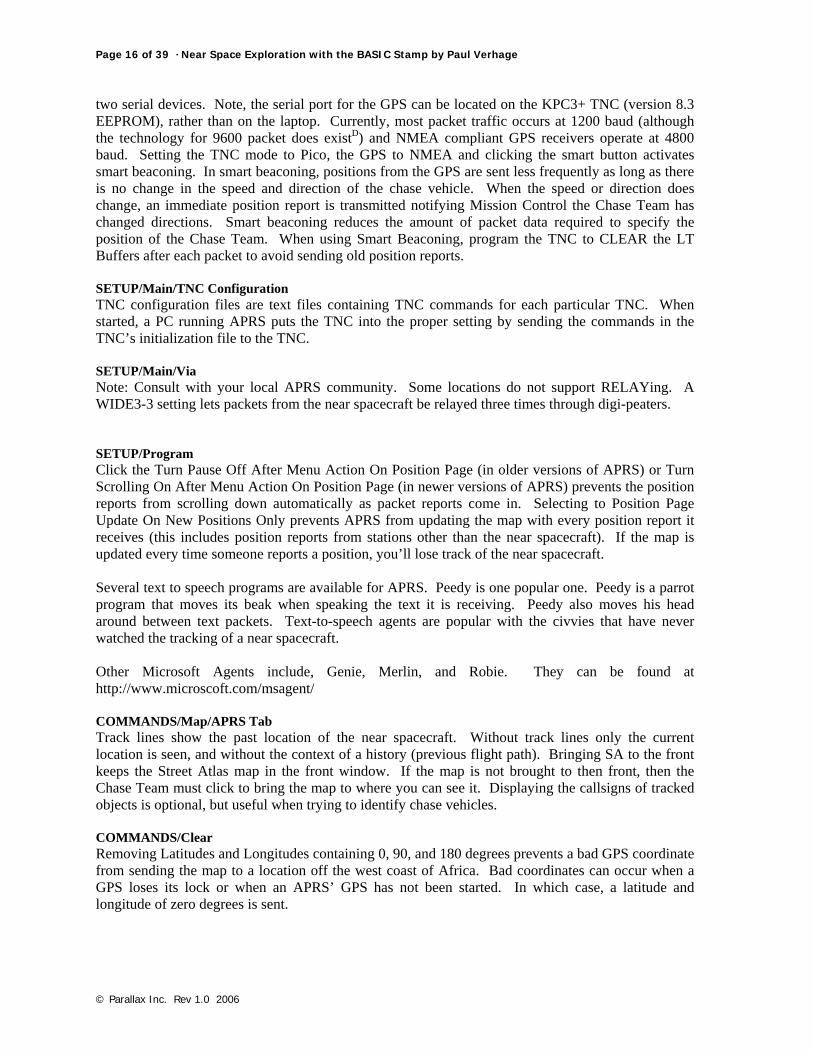
1.1.8. Safety The standard safely rules apply when chasing near spacecraft; everyone wears their seat belts and the driver must keep a safe distance behind the car ahead (at least two seconds is recommended). Laptops In Accidents The position of the laptop running APRS is an important safety issue. The airbags in a car isn’t concerned with the location of a laptop. If an accident should occur, the deployment of the airbag can hurl the laptop with great force. Place laptops where the Navigator can see them but not where an air bag will turn the laptop into a two-pound projectile.
A Safe Laptop
Just A Driver Won’t Do You can tell when the driver is looking at the laptop by how the car drifts out of the lane. Look at how cell phones are becoming a factor in auto accidents. The person who is driving the automobile (the pilot) is doing too many things to be talking to the rest of the Chase Team and watching an APRS display.

Chapter Eleven: Chase And Recovery · Page 21 of 39
© Parallax Inc. Rev 1.0 2006
Don't Track and Drive!
The pilot really needs someone else (the navigator) to perform navigation and communication functions. Don't add to the statistics by trying to run both communication and navigation while you drive the car. Try to have at least two people per vehicle if there's a laptop or cell phone onboard.
Pilot and Navigator
Spare Tire And Tools Every vehicle needs to carry simple repair tools. The extra oil, radiator fluid, or a spare tire and jack may be just the thing to keep a chase from going sour. Just ask TVNSP Chase Team what it’s like to have a flat tire during chase (at midnight no less!).

Page 22 of 39 · Near Space Exploration with the BASIC Stamp by Paul Verhage
© Parallax Inc. Rev 1.0 2006
The Flat Tire
1.2. The Organized Chase
1.2.1. The Chase Leader Someone really needs to coordinate radio frequencies to use and when to change to them, and another person should coordinate the roads to take during the chase. By laying out these functions, someone is responsible for monitoring two important aspects of the chase. A clearly appointed person will reduce the uncertainty of where to turn or what frequency to use during a chase. Note, I'm defining two functions for the Chase Team, but they don't need to be tasked to two separate people. One team member can fulfill both roles.
1.2.2. Bring Something To Eat And Drink Members of the Launch and Chase Team have been up for a couple of hours by the time the chase begins. Their energy levels may be sagging a little bit by now (but you may not notice it because they tend to run on adrenaline during a mission. Bringing a snack and drink for the chase can help keep those energy levels high.
1.2.3. Document On Windshield Who can you afford a HUD (heads up display) in their car? The author finds it incredibly useful to bring a dry erase marker on trips, including chase (it’s funny how such a simple idea surprises people). Document information like frequencies or driving plans on the windshield where they can be found without having to dig around a pile of paper notes. Even if the information is sitting on the passenger seat, taking your eyes off the road to look at them increases the risk of driving. Of course you defeat the usefulness if the windshield is cluttered with factoids. Just write brief statements. After chase, wipe the windshield down with a Kleenex.
1.2.4. The Night Before Launch And Chase Stopping right after launch to call the AAA or to correct a flashing oil light has a way of slowing down a chase. Do the following before a launch
√ Check the car’s fluids

Chapter Eleven: Chase And Recovery · Page 23 of 39
© Parallax Inc. Rev 1.0 2006
√ Check tire pressure √ Fill the gas tank
1.3. Mission Control There should be a controller just for the flight on the amateur radio repeater. This creates a mission control position allowing those who don't chase to be very involved with the flight. The person selected as Mission Control should be familiar with the flight procedures and balloon prediction. A flight may be launched before the next winds aloft report is available, but may recover after its available. Mission Control should know how to run the prediction software (Balloon Track for Windows) and update the recovery prediction during the flight.
1.3.1. Function Of Mission Control While not strictly necessary, a good Mission Control is invaluable. A Mission Control performs the following three actions in support of the Chase Team. 1. Ascent Functions
• Give updated status reports on the near spacecraft • Monitors repeater traffic on the near spacecraft repeater
2. Guide Functions
• Communicate with other individuals who know the area the Chase Team is traveling through • Consults maps of the recovery zone • Forwards information to the Chase Team
3. Recovery Functions
• Makes new recovery zone predictions from current winds as they become available • Posts updated predicted recovery zones
Ascent Functions of Mission Control Depending on how busy the Chase Team is, Mission Control may be in a better position to keep everyone informed on the near spacecraft’s status. Mission Control is the ideal source for those listening to the chase and recovery on the repeater, but who are not otherwise involved with the mission. One of the best ways to get more people involved is to explain to them what is happening during the mission. That burden is not really appropriate for the Chase Team. If a radio repeater is part of the manifest on a near spacecraft, then someone at Mission Control needs to be tasked with controlling communications over the repeater. Occasionally they need to explain to listeners where the repeater is located and how to use it. In addition, Mission Control should monitor callsigns using the repeater to issue QSL cards after the flight. By the way, the QSL cards should be carried inside the near spacecraft. Guidance Functions Of Mission Control Mission Control is in a location that has large tables and no motion. So it is easier for Mission Control to consult maps that it is for the Chase Team. There are times when people listening to the chase on the repeater will be more familiar with the recovery zone or how to get there than anyone in Mission Control or the Chase Team. Mission Control needs to responsible for collecting this information and making it available to the Chase Team. This means Mission Control also needs to control who is speaking to the Chase Team. It is very confusing for the Chase Team that to get multiple and contradicting instructions over the radio.

Page 24 of 39 · Near Space Exploration with the BASIC Stamp by Paul Verhage
© Parallax Inc. Rev 1.0 2006
Recovery Function Of Mission Control Often new winds aloft reports are available after the launch of the mission. Mission Control is in the ideal location to run the new winds aloft reports through Balloon Track and report the new predicted recovery zone. The Balloon Track program should run another set of predictions should be run after the balloon bursts with the Extract feature of Balloon Track. APRS allows positions to be posted. Mission Control should post the updated recovery zone after the balloon bursts. Chase Teams will see this posted location, making it easier to drive there (as opposed to being told where to drive). How To Post A Position In APRS To post an icon at the predicted recovery site of a near spacecraft, Mission Control must send a position report in APRS. These directions explain how to post a location. In APRS, click the Message Screen Enter the location packet in the message window in the following format !3602.654N/11149.559W-Recovery Location Where: The position report begins with an exclamation point (!) No Space Latitude is given in the format of degrees, minutes, decimal point, fractional minutes,N A slash and no Space Longitude is given in the format of degrees, minutes, decimal point, and fractional minutes,W A Dash (-) A Text message, not to exceed 43 characters If the above position report is sent, a message stating Recovery Location would show up at the Grand Canyon.
1.3.2. Good Locations For Mission Control Depending on the ultimate function of Mission Control, it can be located either at someone’s ham shack (usually includes a well equipped APRS station) or in a more public location. When located at home, it’s easier for that person who lives there, especially if the launch is very early. When located at a more public location, it’s easier to get civvies involved with the program. Good public locations are at malls, schools, museums (like aerospace museums), or parks. Get permission top set up Mission Control in a public location, as there’s nothing more embarrassing for a near space program than to have someone ask you to leave. In a public setting, make sure power is available. Determine if the program will have to bring its own tables and chairs. Locating Mission Control in a more public location requires the launch to occur later in the day, unless Mission Control has a captive audience likes scouts or students getting extra credit for attending that early in the morning. When located in a public space, give visitors a chance to talk to the Chase Team. It may be necessary to assign someone to take the role of Public Affairs. Display materials showing the kind of environment conditions the near spacecraft is experiencing. Photographs and video are great to have on hand. Test a private Mission Control before a launch. Test it by monitoring APRS traffic for a couple of hours. Even have someone drive around with the near spacecraft. Set up a public Mission Control the night before launch. Then give it test by monitoring APRS traffic for a while.

Chapter Eleven: Chase And Recovery · Page 25 of 39
© Parallax Inc. Rev 1.0 2006
1.3.3. Equipment Needed For Mission Control The following items are needed for a Mission Control (read, an APRS station). If Mission Control is going to be portable, then keep the equipment in plastic tubs (when possible) along with a laminated list of equipment to verify nothing was left behind.
• PCs or laptops • TNC with spare batteries or a wall-wart • Radio with extra battery of wall-wart • Extension cord • Power strip • APRS on PC • Maps • Documentation from the FRR
2.0 The Recovery The balloon has now burst, and is on its way down. Initially the near spacecraft descends at speeds in excess of 100 mph, even though the parachute is fully opened! Now the Chase Team becomes the Recovery Team and has about an hour before the near spacecraft touches down.
2.1. Making The Final Prediction The true winds aloft are never as they are predicted. On Street Atlas you will notice the near spacecraft deviating from the predicted flight path. This is to be expected, so don’t worry when you see it. However it does mean that your driving plans will have to change to an extent.
2.1.1. Making The Final Prediction For Chase Either let Balloon Track make a prediction based on the balloon’s ascent or make a prediction manually. Click the Extract Data button of Balloon Track to make a prediction based on the wind profile determined by the balloon’s performance. For a manual prediction, take a line from launch site to burst point, and extend it out 50% farther. This method makes the assumptions that the average descent rate is twice as great as the average ascent rate and that the wind profile doesn’t change significantly over the flight. These two assumptions are quite reasonable and helped KNSP make updated predictions for the Recovery Team. The ascent and descent profiles for the near spacecraft are more accurately determined after the first flight.

Page 26 of 39 · Near Space Exploration with the BASIC Stamp by Paul Verhage
© Parallax Inc. Rev 1.0 2006
The 50% Method
2.1.2. Making The Final Prediction For Hiking If the Recovery Team is lucky, they will have GPS data from the near spacecraft as it lands. However, if there's any hills or mountains in the recovery zone, the Recovery Team will get a last GPS report from the near spacecraft when it is still some distance above the ground. Instead of hiking to the last know position, take into account what the surface winds will do the descending near spacecraft. Ask yourself, “What did the near spacecraft do on the way up?” For instance, did it change its direction of travel at a particular altitude? What ever it did on the way up it will do on the way down. You may have a last report of the near spacecraft traveling north at 5,000 feet, but if the traveled west for the first 4,000 feet, then expect to travel west from the last known position. As you get closer to the near spacecraft, look into the current surface winds. A valley can force a change in wind directions that wasn’t seen at launch.
2.1.3. Last Word On Updated Predictions Now is probably the most dangerous time of the chase. Everyone will want to rush to the landing site. This is one justification for being close to the recovery zone before stopping to wait for balloon burst. By being close to the recovery zone, the final chase is more leisurely. So avoid stopping early during the chase and don’t be upset if the near spacecraft lands before the Recovery Team gets there. That said, the KNSP Recovery Team has often been less than a mile of the landing near spacecraft. This is close enough to visually observe the landing. In one particular instance in October 1998, the KNSP Recovery Team observed the near spacecraft under its parachute at an altitude of 2,000 feet

Chapter Eleven: Chase And Recovery · Page 27 of 39
© Parallax Inc. Rev 1.0 2006
AGL and drifting along a county road. The team continued down the road for less than a mile where Dan Miller (KE4SLC) was able to jump out of his car and catch the balloon as it landed. I do not believe this has happened for any other near space flight. It was quite amazing to see. Now that you have finally caught up with the near spacecraft again, it’s time to take a hike and get your equipment back. Suggested here is a list of equipment to bring and how to make the final recovery.
2.2. What To Take On Recovery They can tell you’re a nerd from a mile away when you chase near spacecraft properly. Here are some suggestions on what to take when you chase. Some of them are very important, so please do not skip this section.
2.2.1. Recovery Chic You won’t believe the places a near spacecraft will recover. Ticks, thorns, and poison ivy are just a few of the wildlife waiting for you at recovery. The clothing you wear can make the difference between having an adventure or having a miserable time. Suggested Wear A good pair of boots makes the hike to recovery safer for your feet and ankles. A pair of hiking boots with ankle support helps out when crossing rough or steep terrain. Remember, the near spacecraft is under no obligation to recover on paved roads or sidewalks. Always wear long sleeve pants on chase, even if it’s a hot summer day. Make sure the pants are durable enough they won't rip a part when you walk through a thorny patch. Not only do long pants keep your legs from being ripped up, they also give protection from Lyme disease and Poison Ivy. If you get either of these problems, the recovery will be very memorable. Even with long pants, do a tick check after recovering the near spacecraft. Hats. If you're hiking any distance on a sunny day you'll need the sun protection. Getting heat stroke is another way to create a memorable recovery experience. If I sound a little paranoid, I am being a little paranoid (only a little though). Having suffered through poison ivy and Lyme disease, I can tell you how perfectly miserable they can be. There’s no need for either of them to be the results of a balloon chase. The suggested clothing items aren't very expensive, and in fact you probably already have them. So wear them on chase. Nice To Have Here are two other items found to be useful during chase. First is a pair of rain or mud boots. Several KNSP missions recovered in muddy farm fields. On one mission, members of the Recovery Team spend over ten minutes cleaning the mud from shoes before they could get back into their cars (that means we were ten minutes late for lunch). From that point on, several of us carried an inexpensive pair of rain boots in the trunks of our cars. The rain boots are tall (calf high) and cost $10 at a farm supply store. Another nice item to have is a vest with pockets. Most members of the Recovery Team are carrying an HT and GPS with them. Pants aren't very comfortable when their pockets are filled with bulky items like these. Something like a fisherman, hunter or photographer's vest is ideal.
2.2.2. The Recovery Bag It’s easier to return the near spacecraft to the chase vehicle if you can stuff the parachute and balloon into a backpack or knapsack. By why limit this recovery bag to just hauling parts of the near spacecraft back after it’s found? A backpack filled with recovery gear should be put into one chase

Page 28 of 39 · Near Space Exploration with the BASIC Stamp by Paul Verhage
© Parallax Inc. Rev 1.0 2006
vehicle. The recovery bag is also a great place to store your snacks and drinks. I recommend the following equipment be packed into the recovery bag.
• Tree spikes • Limb Saw • Nylon cord • Fish Weights • Pocketknife or scissors • Film Changing Bag • Nylon Mesh Laundry Bag • Compass • Binoculars
Tree spikes, a limb saw, nylon cord, and fish weights are tools for recovering a near spacecraft caught in a tree. Be aware that in National and State Forests, you probably won’t be allowed to cut limbs from a tree. In that case you will rely on climbing the tree or using a fish weight on the end of a cord to pull the near spacecraft lose. Bring a pocketknife or scissors to cut load lines. In the field it is easier to cut the lines than to try and untie them. Save untying knots for home, after you’ve recovered the near spacecraft and had lunch. Never open cameras in the daylight to retrieve their film. The cold of near space may have jammed the film rewind function of the camera. Use the film-changing bag when removing the film from a camera in the field. While a roll of film isn’t expensive, the cost or replacing the image on the film may be impossible. The film-changing bag is your insurance. At times, it is desirable to remove some items from inside the near spacecraft at the time of recovery, in the field. Please don’t be a litterbug. Upon opening a near spacecraft in the field, Styrofoam peanuts will blow all over the place. You should reuse the clean Styrofoam peanuts and try to keep the mess down. Use a nylon mesh bag to collect the Styrofoam peanuts inside the modules of the near spacecraft. A GPS receiver indicates heading only when it is moving. A compass indicates headings independent of whether it is moving. So toss an inexpensive compass into the recovery bag. Binoculars let Recovery Teams cover an area faster than they can on foot. They also eliminate false sightings without spending the time to investigate them on foot. When possible, get up to a high spot and you can scout around with the binoculars. Nice To Have The following items would be nice to carry into the field.
• Walking stick • First aid kit • Camera • Foxhunter Antenna For a HT • Amplifying Microphone (Big Ear) • Module Carrier (to be built)
As any hiker can tell you, a walking stick is useful for rugged terrain. That extra foot on the ground helps prevent you from tripping up. Pick up a basic first aid kit from an outdoor supply store. Each recovery is unique and there should be a record the condition of the recovered near spacecraft and it’s terrain. If a camera is tossed inside the recovery bag, be sure the camera lens is covered. If not, then the lens can be scratched during the hike to the near spacecraft. Alternatively, the camera can be carried on a camera strap. However, if you have ever had the opportunity to carry a swinging camera with you on a hike, you’ll realize how unpleasant that can be as the heavy metal camera slams into your chest with each footstep. Fortunately a restraining belt is available at photography and outdoors stores. The nylon belt is adjusted to size and wraps around your chest. A neoprene disk in the belt

Chapter Eleven: Chase And Recovery · Page 29 of 39
© Parallax Inc. Rev 1.0 2006
traps the camera between your chest and the neoprene pad, preventing the camera from swing around. Best of all, the neoprene pad lets you pull the camera free, where it is instantly available to take photographs. There’s no need to open the recovery bag just to pull the camera out. If APRS onboard the near spacecraft has failed but the near spacecraft is still transmitting, then radio direction finding (RDF), or foxhunting is the only reasonable method to find the near spacecraft. Foxhunting antennas for HTs are available. At least one should be carried on each mission as it is better to have carried one and not needed it that is to leave one at home when your needed it. There’s no need to carry RDF equipment in the recovery bag. Just store the RDF equipment in the car until it is needed. It’s beyond the scope of this book to teach you to foxhunt. There are books that go into detail that you should reference. Basically foxhunting involves finding several azimuths to the transmitter from several locations. The intersection of these azimuths indicates the location of the hidden transmitter. EOSS has found they get a lot more support in recovering the near spacecraft if they let foxhunters look for the near spacecraft first. There’s no reason foxhunters can’t be involved with a chase and recovery when APRS is working. Letting them practice on a perfectly good near spacecraft trains them for those times when the near spacecraft may not be perfectly good. A near spacecraft on the ground may hide itself with bushes, tall grasses, or trees. Even when you are only 100 feet (which is a typical precision of a GPS receiver) away from such a hidden near spacecraft, you will have difficulty in locating it. The audio beacon shines when foliage hides the near spacecraft. Just listen for the 90 dB beep! You may want to add an amplifying microphone (Big Ear) to your recovery pack, in case you are still too far away from the near spacecraft to hear it. Besides, using a Big Ear is a really cool thing to do! The Module Carrier After the near spacecraft is recovered, it needs to be carried back to the chase vehicles. It takes two hands to safely carry each module back. This means each person with a module has no free hands during the hike back. Depending on the terrain, this can be a dangerous situation that leads to injuries and damaged modules when someone slips or falls. I myself have slipped while carrying modules, once on a mountain trail and another time while walking on level ground. I’ve come up with this idea (but have not yet tested it) and believe it will help prevent accidents, which may damage a module. The idea is to mount the modules to a stick that can be carried over one shoulder or between two people.
The Module Carrier
Materials • ¾” or 1” diameter wooden dowel (broom handle) • 200# test Dacron line • Four snap swivel bearings • Thin heat shrink tubing, large enough to cover a knot in the Dacron line • Four wide rubber bands
Procedure
√ Cut the dowel to a length between four and six feet

Page 30 of 39 · Near Space Exploration with the BASIC Stamp by Paul Verhage
© Parallax Inc. Rev 1.0 2006
√ Set two modules next to each other, with about a one foot gap between them √ Mark on the dowel the location where the module’s spilt rings touch the dowel √ Drill four small holes through the dowel for the Dacron line to pass through √ Cut four pieces of Dacron line to a length of three feet each √ Melt the cut ends to keep them from unraveling √ Find and mark the center of the lines √ Pass each line through one hole in the dowel and center the lines √ Tie two knots in each line trapping the lines in the dowel √ Cut eight pieces of heat shrink tubing, one inch long √ Slide a length of heat shrink tubing on to each end of the Dacron line √ Tie snap swivels at the end of each Dacron line √ Slide the heat shrink over each knot and shrink
Using The Module Carrier
√ Wrap the Dacron lines around the dowel before taking the carrier out √ Use the rubber bands to keep the lines from unwinding √ Removed the modules from the parachute and balloon √ Note: The parachute and balloon should be carried in the recovery bag √ Latch the snap swivels to split rings of each module
2.2.3. HT and GPS Anytime recovery crews divide up and are out of sight, they must carry an HT. Never let anyone separate from the group without having some way to keep in contact. Not only will radios help locate a lost or injured team member; they also get the entire Recovery Crew to the near spacecraft quickly once it is found. Think how frustrated you’d be if the near spacecraft was found and brought back to the car before you had a chance to see it or if you had to wait for someone to come back from the bush after the near spacecraft had been recovered an hour ago. Bring a GPS receiver if the near spacecraft has recovered in an area like a forest without hiking trails. You’ll be surprised how fast you can get turned around walking among trees with no external source of direction. Before leaving the cars and starting the hike to the near spacecraft, program two positions into the receiver. The first is of the chase vehicles. This is especially necessary if the hike is going to be long and it might be difficult to find the cars again. Error on the side of caution and mark the location of the car if there’s the slightest chance of possibly getting lost. The second location is the last known location of the near spacecraft into the GPS. Depending on the last recorded position of the near spacecraft, the GPS can then lead an on-foot Chase Team to the near spacecraft's location. Otherwise it gives them a starting position to begin the search for the near spacecraft. Programming Positions Into A Garmin Handheld GPS Receiver The Garmin series of handhelds are probably the most popular GPS receiver. Here’s how I add a new location to my Garmin GPS48, which should be similar to other Garmin GPS receivers
√ Press the MARK button a second time to record your current position √ Press the Up Arrow button to the name field √ Press the ENTER button to edit the name field √ Use the Right Arrow button to select the next character field √ Use the Up or Down Arrow button to change each character √ Note: Use a meaningful name, as you’ll have to select this location form the GPS receiver’s
waypoint list √ Press the ENTER button to exit the name field

Chapter Eleven: Chase And Recovery · Page 31 of 39
© Parallax Inc. Rev 1.0 2006
√ Press the Down Arrow button to select the save option √ Press the ENTER button to save location √ Press the PAGE button until the GPS is on the Main Page (MAIN MENU) √ Press the Down Arrow button to high the NEAREST WPTS option (nearest waypoints) √ Use the Down Arrow button to highlight the saved location √ Press the ENTER button to select the waypoint √ Press the Down Arrow button to enter the latitude position field √ Press the ENTER button √ Press the Right Arrow button to move the cursor to the latitude numeric value that needs to
be changed √ Press the Up or Down Arrow button to change the numeric value √ Continue pressing the Right Arrow button to enter the longitude position field √ Press the Right Arrow button to move the cursor to the longitude numeric value that needs to
be changed √ Press the Up or Down Arrow button to change the numeric value √ Press the ENTER button √ Press the GOTO button √ Use the Down Arrow button to highlight the saved location √ Press the ENTER button to select the waypoint √ Start walking and follow the compass rose to the last known location of the near spacecraft
2.2.4. Get Permission Before Going Into The Field Chances are the near spacecraft has recovered on private property. If at all possible, contact the landowner before recovering the near spacecraft. However, there may be times when it lands in private property miles away from the owner or the landowner cannot be found. If a landowner cannot be found, then contact a neighbor and explain what you want to do. In some cases the neighbor can locate the landowner when you can’t. When a landowner or neighbor cannot be located, KNSP has recovered the near spacecraft quickly. Do not leave the burst balloon or any other debris behind. Do not damage private property while recovering the near spacecraft. Close all gates that you opened. Treat private property like you'd want someone to treat yours.
2.2.5. Carry Snacks, Drinks, And A Hat If the hike to the near spacecraft is any significant distance or the terrain is difficult, each Recovery Crew needs to carry something to eat and drink. Going on a hike is not the time to diet.

Page 32 of 39 · Near Space Exploration with the BASIC Stamp by Paul Verhage
© Parallax Inc. Rev 1.0 2006
Recovery Crews need to keep their bodies functioning properly. Energy and hydration levels can drop fast when hiking. To keep the pace of the hike brisk and the recovery short, eat and drink during the hike to the near spacecraft. This is less of an issue for KNSP in Kansas, but a significant concern for TVNSP in Idaho with Idaho’s rugged terrain. Most near space missions take place in summer months. Hiking significant distances in the sun without a hat is asking for trouble. Everyone on foot needs to bring a hat with a brim for protection from the sun.
2.3. Powering Down, Documentation, And Lunch You’ve finally reached the recovered near spacecraft. Now what?
2.3.1. Site Documentation The following applies if there is no immediate danger to Recovery Crews of the near spacecraft. Avoiding hazards takes precedence over site documentation. Before handling or moving the recovered near spacecraft, document the recovery. Most and perhaps all near space Recovery Crews record the recovery site. Its location is recorded in a GPS receiver and the location photographed. Record the condition of the near spacecraft photographically. Identify and damage experienced by the near spacecraft during the flight and landing (most damage is incurred during landing). This way any damaged incurred during the trip home can be separated from mission damage. The way the near spacecraft is laid out can indicate its direction of movement. Seldom will the near spacecraft be positioned in a single heap of Styrofoam and fabric. More typical, the near spacecraft is laid out in a line, with the modules at one end and the parachute and balloon at the other end. Here are a couple more things to document.
• Is the balloon free of the parachute? • Is there a debris field, was the near spacecraft dragged by the parachute after landing? • Is there unusual damage, for instance, did the near spacecraft recover on a rock or fence?

Chapter Eleven: Chase And Recovery · Page 33 of 39
© Parallax Inc. Rev 1.0 2006
• Are experiments in the positions expected, for instance, are droppers retracted and samplers closed?
• How many photographs does the camera claimed to have taken? • Has the camera rewound the film?
Recovered Near Spacecraft
2.3.2. Power Down And Disassembly You may want to generate a Power Down and Disassembly checklist for the near space missions. Here’s a suggested checklist, similar to what KNSP and TVNSP has used.
√ Shut off audio locator beacon (While helpful in locating the near spacecraft, these beacons are a major pain to work close to)
√ Shut off power to modules (Main, Servo, TNC, and HT) √ Disconnect link lines between modules √ Disconnect the umbilical √ Shut down the camera √ Rewind the camera’s film √ Open camera and remove film in a changing bag √ Collect experiments that need to be removed from the near spacecraft (Like biological
samples) √ Pack removed experiments into their storage and transport container (KNSP transported
Petri dishes in an ice chest) √ Cut the balloon loose from the parachute √ Disconnect the parachute shroud lines from the top module √ Roll up the parachute √ Pack the parachute and balloon into the recovery bag √ Scout the recovery area for loose materials (Pick after yourself) √ Say thank you to the landowner and get their address (Send them photographs taken by the
near spacecraft) Once back to the cars, let anyone who couldn’t go on the hike see the modules. I know I keep stressing this, make sure everyone who is present see the recovered modules. On my first chase I arrived a little late and didn’t get a chance to go recover the capsule and not much of a chance to see the recovered capsule. Let everyone see the equipment and answer questions about how it works and

Page 34 of 39 · Near Space Exploration with the BASIC Stamp by Paul Verhage
© Parallax Inc. Rev 1.0 2006
how it was recovered. You never know when a new chase crew will become one of your greatest crewmembers or begin designing their own modules to launch.
Outstanding in their field – Loading the modules
Afterward, load up the modules and other recovery equipment. If you recovered in a muddy field, doff your mud boots and put on your clean shoes. Determine where the Recovery Crew wants to eat lunch and how to get there. Make sure everyone present knows how to get back to the main road. Be sure to ask who wants photographs.
2.3.3. Lunch Ideally, lunch is at a restaurant located near a one-hour photo processor. Drop off any film at the processors and request enough copies for everyone. Inform the photo lab technician that these are photographs taken at high altitude where the skies will turn black. Some machines in photo labs attempt to balance out the colors on photographs. In that case, images with lots of contrast can end up being printed gray. Most of the Chase Team will probably want a copy of the pictures, so get a count and have enough copies made. After one near space mission, KNSP blitzed the Lawrence, Kansas Wal-Mart photo lab with copy requests. After dropping off our photographs, the lab was no longer one-hour. The photo lab was telling customers to expect their photographs in an hour and a half.

Chapter Eleven: Chase And Recovery · Page 35 of 39
© Parallax Inc. Rev 1.0 2006
Lunch
Next, head on over to the restaurant. In some cases, KNSP and TVNSP crews have split up, with one group reserving room at the restaurant while a second group dropped off the film. There may be a bunch of you, be sure the restaurant can handle all of you. Ask for a location where tables can be pushed together and that is near an outlet, as you’ll need power for the laptops. Bring the following items to lunch (depending on what experiments were flown)
• Laptop • Digital camera cable • Thermochron reader • Extra diskettes and labels • Near spacecraft with Flight Data Recorder
I toss my digital camera downloading cable and Thermochron Reader into my laptop bag, so I can’t forget them. The extra diskettes are for Recovery Crews who want their own copy of the data from the mission. During lunch, KNSP and TVNSP crews do the following
√ Download digital photographs √ Download Thermochron data √ Download flight data √ Copy APRS logs √ Make diskette copies for everyone who wants one √ Eat lunch!

Page 36 of 39 · Near Space Exploration with the BASIC Stamp by Paul Verhage
© Parallax Inc. Rev 1.0 2006
I find these lunches to be one of the best aspects of the chase. It’s a good meal with good company that has similar interests and now a shared experience. After lunch, if you borrowed a launch site, head back and finish cleaning up the site. Don't lose a good launch site by leaving equipment lying around all day.
Good To Know - An Introduction To Packet And APRS There are several digital communication modes in use today. From the old Radio Teletype (RTTY) which sent simple text data at 60 words per minute with no error correction, to PACTOR used on HF radios, to packet radio. Before 1980, packet radio did not exist. In March of that year, the FCC granted amateur radio operators permission to transmit ASCII data over radio. Canadians were granted permission to transmit ASCII data over radio earlier and at the time of the FCC decision, were designing a protocol for what would become packet radio. Along with the protocol, A Canadian by the name of Doug Lockhart (VE7APU) was developing a device for transmitting and receiving packet radio. The device converted the binary ASCII text into a series of tones in a process referred to as modulating. The device keyed its radio and transmitted the tones. At the receiving end, a separate device received the tones and demodulated then, that is converted the tones back into binary-based ASCII. The process of modulating and demodulating signals is used to name the device, the modem (MODulate-DEModulate). The Canadians further when on to give this radio modem a new name, the terminal node controller (TNC). By the end of 1980, Hank Magnuski (KA6M) of the California Bay Area developed his own TNC and began digipeating on two meters. Local amateur radio operators joined with Hank, forming the Pacific Packet Radio Society. Later other groups formed, including AMRAD and TAPR (more about TAPR, later). A popular networking protocol at the time, called X.25, was adapted to packet radio use. The modified protocol was renamed to amateur X.25, or AX.25 TAPR (Tucson Amateur Packet Radio) formed in 1981 to experiment with packet. Two members of TAPR developed their first successful prototype TNC on 26 June 1982. By 1983 they were selling a TNC of their own design, the TNC-1. TAPR went on to develop standard designs for TNCs in the TNC-1 and TNC-2. The TNC-1 that forms the basis for the majority of the TNCs we use today and the TNC-2 that was the first commercially available TNC kit available to the public. Today there are many TNCs on the market. The three TNCs mentioned in this book are the Kantronics KPC 3+, the Byonics Tiny Trak II and Tiny Trak III, and Dr. Clement’s (now Spacecraft Kits) MIM. Today you’ll find packet on VHF and UHF radios communicating at 1200 baud. Compare this to the much older RTTY, which transmits data at only 45 baud. Packet can send the entire ASCII character set and binary files. RTTY is limited to the numbers, letters, and some control characters. The only digital communication mode older than RTTY is CW (Morse code). APRS, the Automatic Position Reporting System, made modern amateur near space exploration possible. Early amateur near space flights relied on radio direction finding to recover capsules after they landed. Flight data collected during the mission was encoded on a radio carrier that had to be interpreted during or after the flight. The amount of data that could be collected was limited as was the flexibility in designing experiments for near space. Without APRS we wouldn’t have as much detailed data about the flight as we can now have. Currently the National Weather Service relies on this old method of collecting and transmitting weather conditions from radiosondes to the ground. Packet radio originally started out as a DOS program that displayed text data on a PC monitor. With the advent of APRS, this data is now displayed graphically. The difference between packet radio and

Chapter Eleven: Chase And Recovery · Page 37 of 39
© Parallax Inc. Rev 1.0 2006
APRS is the same difference as between MS-DOS and Windows. They both work with the same data, but APRS displays the data in a graphical format that is more intuitive. The term APRS is only half descriptive. Not only is position data from a GPS receiver displayed graphically, but so are sensor data and messages. How the data is displayed on the monitor depends on how the data is formatted within the packet. Because data follows a defined format, each PC running APRS can quickly parse and display the data. This makes APRS a real-time method for displaying information. The series of rules used to format pieces of data according to their nature is referred to as a protocol. If you want to send APRS data in a way that it is presented correctly, then the data must be formatted according to the protocol for that data. Bob Bruninga (WB4APR) initially developed the APRS protocol and a program for displaying data written in his protocol on PCs running MS-DOS in 1992. The Sproul brothers, Keith (WU2Z) and Mark (KB2ICI) developed the Macintosh (1994) and Windows versions (1996) of APRS. APRS centers around a map displayed on the monitor of a PC or LCD screen of a laptop. Most packets transmitted for APRS are displayed some place on that map. Data sent over packet radio doesn’t get transmitted just as you enter it on the PC. Depending on the length of the message or data being sent, it may be broken into shorter length blocks of data, or packets. Each packet is transmitted with information used to verify the content of the packet was decoded properly at the receiving PC. In some cases, corrupted packets can be corrected by this verification information. Each packet is preceded with the callsign and SSID of the station transmitting it. You should be familiar with callsigns, but what about SSIDs? The SSID is the Secondary Station Identifier of a packet station. It shows up as a modification to a callsign that allows multiple devices to use the same callsign. In my chase vehicle my callsign and SSID would be KD4STH-9 and my near spacecraft’s callsign and SSID is KD4STH-11. With the SSID, one can operate several packet stations and know which station is being referenced. Also, the SSID graphically explains how APRS is to display the icon for that that station. So the –9 SSID is displayed as a car icon while the –11 SSID is displayed as a hot air balloon icon (okay, so a hot air balloon is not quite right for a near spacecraft, but it’s close enough). Think of the confusion that would result if no one understood if the packet they just received was from your chase vehicle (SSID-9) or your near spacecraft (SSID-11). In the olden days, most packet data was sent to a specific callsign and SSID. In this case, the intended recipient of the message was also added to the packet. However, packets formatted for APRS are preceded with a UI, or unnumbered information frame. These packets are not meant for a specific individual, but instead are meant for anyone listening. These packets typically contain the location of the transmitting station (usually from a GPS receiver at the station) and a message in the proper format. The message is then displayed according to the APRS protocol at the location specified in the packet. Everyone running an APRS terminal sees the data displayed the same way and in the same location on the map. APRS makes a very fast way to send information to everyone. Every APRS station must include a TNC and radio. A GPS receiver and PC is optional. Fixed locations don’t require a GPS receiver, as they never move. However, the position of the station must be known before going on air. The coordinates are coded into the station and transmitted with each packet. APRS stations that just transmit status information do not require a PC running APRS to display incoming data. A typical station without a GPS receiver and PC is a weather station. Examples of status data transmitted by an APRS station include weather conditions, speed and heading, current status, and announcements and bulletins. The APRS protocol is very flexible and capable of displaying a wide variety of information.E

Page 38 of 39 · Near Space Exploration with the BASIC Stamp by Paul Verhage
© Parallax Inc. Rev 1.0 2006
Near Space Humor - Top Six Chase Songs 1. The Battle of New Orleans 2. On The Road Again Willy Nelson 3. William Tell Overture Rossini 4. Ride of the Valkryies Richard Wagner 5. When Johnny Comes Marching Home (This reminds me of the bomber scenes in the movie, Dr. Strangelove) 6. Carefree Highway Gordon Lightfoot My Modification To “On The Road Again” (With apologies to Willie Nelson) On the road again, Just can’t wait to get on the road again, My life’s love is balloon chasing with my friends, And I can’t wait to get on the road again On the road again, Traveling bad roads I’ve never been, Searching for capsules I’ll never find again, I can’t wait to get on the road again. On the road again, Looking like the X-Files, we drive down the highway, We’re the best of friends, Hoping the balloon’s drifting our way, And our way…. Is on the road again. Just can’t wait to get on the road again, My life’s love is balloon chasing with my friends, And I can’t get on the road again, And I can’t get on the road again. A The values are the average of the first six satellite vehicles for three consecutive records taken over a period of a few minutes before the movement of satellites could influence the results. B This should be just greater than the thickness of window glass in the car. C For example, a sign warning people not to open the door (to prevent pulling on the antenna cables) D Most amateur radios do not pass a 9600 baud signal. To use 9600 baud packet requires radios with direct connections to the transmitter modulator varactor and discriminator, which is not available on most amateur radios (notes from Mike Manes, EOSS). E Information for this précis was found at the following sources. Consult them for more in depth information. APRS Protocol Reference, The APRS Working Group, http://www.tapr.org

Chapter Eleven: Chase And Recovery · Page 39 of 39
© Parallax Inc. Rev 1.0 2006
Getting On Track With APRS, Stan Horzepa (WA1LOU) Introduction To Packet Radio, Larry Kenney (WB9LOZ), http://www.choisser.com/packet/part01.html http://home.teleport.com/~nb6z/frame.htm