chapter eleven — visual aids — day · pdf filechapter eleven — visual aids...
TRANSCRIPT
Visual Aids – Day
April 2001
CHAPTER ELEVEN — VISUAL AIDS — DAY Page
1 — APPLICABILITY 11 - 1 2 — GENERAL 11 - 1 3 — REMOVAL OF VISUAL AIDS 11 - 1 4 — USE OF COLOURS 11 - 1 5 — MARKINGS 11 - 2 6 — MARKERS 11 - 2 7 — RUNWAY MARKINGS 11 - 3
General 11 - 3 Pre-runway-end markings 11 - 4 Runway centreline markings 11 - 5 Runway designation markings 11 - 5 Runway end markings 11 - 7 Runway side-stripe markings 11 - 7 Runway fixed distance markings and runway touchdown zone markings 11 - 7 Runway threshold markings 11 - 8 Temporarily displaced threshold markings 11 - 8 Runway land and hold short and runway hold short markings 11 - 15 Runway strip markers 11 - 15
8 — TAXIWAY MARKINGS 11 - 17 Taxi guideline markings 11 - 17 Taxi holding position markings 11 - 17 Taxiway intersection markings 11 - 19 Taxiway edge markers and markings 11 - 19 Holding bay markings 11 - 19 Taxiway pavement-strength limit markings 11 - 20
9 — APRON MARKINGS 11 - 20 Apron taxi guideline markings 11 - 21 Apron edge markings 11 - 21 Parking clearance line 11 - 22 Aircraft type limit line 11 - 22 Parking weight limit line 11 - 23 Leased area line 11 - 23 Equipment clearance line 11 - 24 Equipment storage and apron road markings 11 - 24 Aircraft parking position markings 11 - 25 Lead-in line 11 – 25 Taxi lead-in line designation 11 – 26

Rules and Practices for Aerodromes Chapter 11
April 2001
9 — APRON MARKINGS (Continued) Pilot turn line 11 - 28 Primary aircraft parking position markings 11 - 28 Marshaller stop line 11 - 28 Pilot stop line 11 - 29 Alignment line 11 - 29 Secondary aircraft parking position markings 11 - 30 Keyhole marking 11 - 30 Triangle marking 11 - 31 Lead-out line 11 - 31 Designation markings 11 - 32 Aircraft parking position designation 11 - 32 Designation characters for taxi and apron markings 11 - 33
10 — TUG OPERATOR GUIDANCE MARKINGS 11 - 35 Aircraft push-back lines 11 - 35 Tug parking position lines 11 - 35 Towbar disconnect markings 11 - 36 Push-back limit markings 11 - 36 Push-back alignment bars 11 - 37 Passenger path markings 11 - 37 Typical apron markings 11 - 37
11 — MARKINGS OF AERODROME FACILITIES FOR HELICOPTERS 11 - 39 Helicopter landing and lift-off area markings 11 - 39 Helicopter apron markings 11 - 39 Helicopter parking position markings 11 - 39 Helicopter taxi guideline designation 11 - 40 Helicopter parking position numbers 11 - 41 Helicopter apron edge markings 11 - 41 Typical helicopter apron markings 11 - 42
12 — MOVEMENT AREA GUIDANCE SIGNS 11 - 44 General 11 - 44 Dimensions, location and lettering 11 - 44 Structural 11 - 45 Illumination 11 - 45 MAGS with mandatory instructions 11 – 46 MAGS with information 11 - 48

Visual Aids – Day
April 2001
13 — UNSERVICEABILITY MARKINGS AND MARKERS 11 - 51 Unserviceability markings 11 - 51 Unserviceability markers 11 - 52 Works limit markers 11 - 52 Signal areas and ground signals 11 - 52
14 — WIND DIRECTION INDICATORS 11 - 52 15 — OBSTACLE MARKINGS 11 - 54
General 11 - 54 Obstacle marking implementation 11 - 54 Marking of obstacles 11 - 54 Marking of temporary and transient obstacles 11 - 56
16 — MARKING OF GLIDER RUNWAY STRIPS 11 - 57

Rules and Practices for Aerodromes Chapter 11
April 2001
THIS PAGE INTENTIONALLY LEFT BLANK

Visual Aids – Day
November 1990 11 – 1
CHAPTER 11 VISUAL AIDS — DAY
1 — APPLICATION 1.1 Operators of aerodromes established under the Air Navigation Regulations 1947, and holders of aerodrome licences issued under regulation 88 of the Civil Aviation Regulations 1988 are required to provide, and maintain, at or in the vicinity of their aerodrome, visual aids of the type approved by the Authority.
1.2 This chapter specifies the Authority’s approved visual aids. Visual aids not conforming to those specified in this chapter are not to be used unless the Authority has been given specific approval, in writing, to do so.
2 — GENERAL 2.1 Visual aids are cues for pilots, marshallers, air traffic controllers and ground vehicle drivers to help them in ensuring safe aircraft operations. Visual aids assist pilots to locate an aerodrome, determine the areas of an aerodrome upon which it is safe and permissible to land and take-off, taxi aircraft safely on the movement area, and precisely position aircraft on the apron.
2.2 Visual aids comprise markings and markers, lights and beacons, and wind direction indicators. This chapter deals only with markings, markers and wind direction indicators intended to be clearly visible by day. Lights and beacons, which are meant to be visible at night, and also during the day when visibility is poor, are dealt with in Chapter 12.
2.3 Although specifications are given here in metric measurements, existing visual aids which were made to Imperial measurements may continue to be used until replacement is required for other reasons. However, new visual aids are to be made and located in accordance with the metric measurements.
2.4 Visual aids provided must be accurate and unambiguous as any incorrect visual aids, or incorrectly place visual aids, would be a hazard to aviation safety.
3 — REMOVAL OF VISUAL AIDS 3.1 When an aerodrome, or part of an aerodrome, is to be closed permanently, all visual aids on the closed aerodrome or on the part of the aerodrome to be closed, visible from the air, are to be removed or obscured, except for unserviceability markings or markers, where required.
4 — USE OF COLOURS 4.1 Colours used for VGA are to conform to the Australian colour standard AS 2700-1985 as set out in Fig 11.1 below: Colour AS Colour Code AS Colour Name Blue B 41 Blue Bell Green G 35 Lime Green Orange X 15 Orange Red R 13 Signal Red Yellow Y 14 Golden Yellow

Rules and Practices for Aerodromes Chapter 11
11 – 2 November 1990
5 — MARKINGS 5.1 Markings are to be clearly visible against the background upon which they are placed. On a surface of light colour, a contrasting black surround is to be provided to improve the visibility of the marking.
5.2 Where provided, the width of the black surround should ensure an adequate visibility contrast. In the case of line markings, the width of the black surround on either side of the marking is not to be less than the width of the line.
6 — MARKERS 6.1 Markers are to be used on unpaved areas in lieu of markings. They are to be either cones or gables.
6.2 Standard cones are to have a height (h) of 0.5m and a base diameter (w) of 0.75m. They are to be painted in a variety of colours, in accordance with the specific information being conveyed, as detailed in Fig 11.2 below.
Taxiway and apron edge marker (yellow)
Helicopter apron edge marker (blue)
Runway strip marker (white)
Note: Runway marker (white h=0.3m, w=0.4m)
Unserviceability marker (white and red)
Runway strip marker (displaced threshold)
(split white and background colour)
Works limit marker (orange)
Fig 11.2 - Cone markers
Visual Aids – Day
June 1998 11 – 3
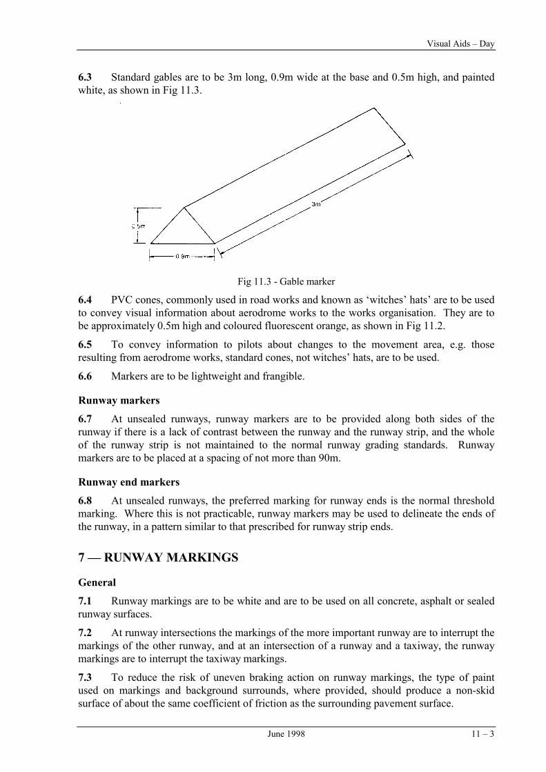
6.3 Standard gables are to be 3m long, 0.9m wide at the base and 0.5m high, and painted white, as shown in Fig 11.3.
Fig 11.3 - Gable marker
6.4 PVC cones, commonly used in road works and known as ‘witches’ hats’ are to be used to convey visual information about aerodrome works to the works organisation. They are to be approximately 0.5m high and coloured fluorescent orange, as shown in Fig 11.2.
6.5 To convey information to pilots about changes to the movement area, e.g. those resulting from aerodrome works, standard cones, not witches’ hats, are to be used.
6.6 Markers are to be lightweight and frangible.
Runway markers
6.7 At unsealed runways, runway markers are to be provided along both sides of the runway if there is a lack of contrast between the runway and the runway strip, and the whole of the runway strip is not maintained to the normal runway grading standards. Runway markers are to be placed at a spacing of not more than 90m.
Runway end markers
6.8 At unsealed runways, the preferred marking for runway ends is the normal threshold marking. Where this is not practicable, runway markers may be used to delineate the ends of the runway, in a pattern similar to that prescribed for runway strip ends.
7 — RUNWAY MARKINGS
General
7.1 Runway markings are to be white and are to be used on all concrete, asphalt or sealed runway surfaces.
7.2 At runway intersections the markings of the more important runway are to interrupt the markings of the other runway, and at an intersection of a runway and a taxiway, the runway markings are to interrupt the taxiway markings.
7.3 To reduce the risk of uneven braking action on runway markings, the type of paint used on markings and background surrounds, where provided, should produce a non-skid surface of about the same coefficient of friction as the surrounding pavement surface.

Rules and Practices for Aerodromes Chapter 11
11 – 4 June 1998
Pre-runway-end markings
7.4 The pre-runway-end marking is to be used where an area exceeding 60m in length before the runway has a sealed, concrete or asphalt surface, and is not suitable for normal use by aircraft. This marking is to consist of yellow chevrons, spaced 30m apart, comprising lines 0.9m wide and angled at 45 degrees to the runway centreline, and is to terminate at the runway end marking, as shown in Fig. 11.4.
7.5 The area marked by the pre-runway-end marking will not normally be used for landing or take-off. If this area is declared as a stopway, it may only be used by an aircraft in the case of an abandoned take-off from the other direction under emergency conditions.

Visual Aids – Day
November 1990 11 – 5
Runway centreline markings
7.6 The runway centreline marking is to be provided on all sealed, concrete or asphalt runways to give pilots directional guidance when landing or taking-off. In the case of runways of 18m width, runway centreline marking may be omitted if runway side stripe markings are provided.
7.7 Runway centreline marking is to consist of a line of uniformly spaced gaps and white stripes as shown in Fig 11.5. The combined overall length of a stripe and a gap (G) is to be not less than 50m and not more than 75m. The length of each stripe is to be at least equal to the length of each gap, or 30m, whichever is greater. The first stripe is to commence 12m from the runway designation number.
7.8 The width (W) of the runway centreline marking is to be as follows:
(a) 0.3m on all non-instrument runways, and instrument non-precision approach runways where the code number is 1 or 2;
(b) 0.45m on instrument non-precision approach runways where the code number is 3 or 4, and Category I precision approach runways; and
(c) 0.9m on Category II and Category III precision approach runways.
Fig 11.5 - Runway centreline markings
Runway designation markings
7.9 Runway designation markings (also known as runway numbers) are numbers painted at the ends of runways to help pilots identify the runway they are landing on. They are to be provided at the thresholds of all sealed, concrete or asphalt runways.
7.10 The runway designation marking is to consist of a two-digit number. The number is to be derived from the magnetic bearing of the runway centreline, when viewed from the direction of approach, rounded to the nearest ten degrees. If a bearing becomes a single digit number, an `0' is to be placed before it. If a bearing becomes a three-digit number, the last `0' digit is to be omitted. For parallel runways appropriate letters L(left), C(centre) or R(right) are to be added to the two-digit number.
7.11 The number selected for a runway designation marking is to be acceptable to the Authority. When two or more runway ends have designations which may be confusing, either on the same or a nearby aerodrome, the Authority will determine the designations to be used.
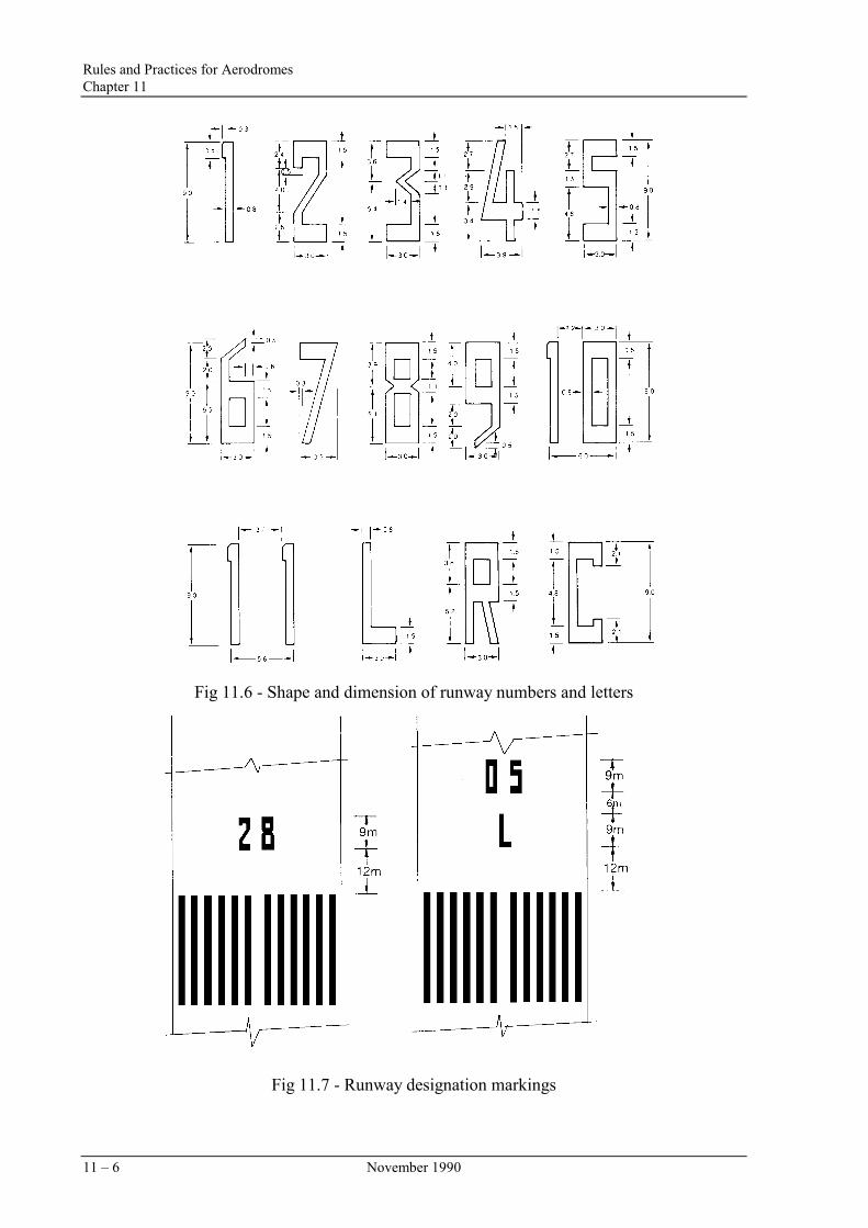
7.12 The shape and dimensions of the numbers and letters to be used as runway designation markings are shown in Fig 11.6 (over page). The location of the marking on the runway is to follow the dimensions shown in Fig 11.7.
7.13 The runway designation number should be provided, as far as practicable, at the thresholds of an unpaved runway.
Rules and Practices for Aerodromes Chapter 11
11 – 6 November 1990
Fig 11.6 - Shape and dimension of runway numbers and letters
Fig 11.7 - Runway designation markings

Visual Aids – Day
Runway end markings
7.14 The runway end marking is a white line, 1.2m wide, extending the full width of the runway, to be used to mark the end of runways. It is to be provided on all sealed, concrete, or asphalt runways, as shown in Fig 11.8. Where the threshold is located at the end of the runway, the runway end marking will coincide with the corresponding part of the threshold marking.
Fig 11.8 - Runway end marking
Runway side-stripe markings
7.15 The runway side-stripe marking is to consist of two continuous (except where broken for taxiways and other runways) white lines, the same width as the runway centreline marking, to be used on all sealed, concrete, or asphalt runways to delineate the width of the runway. In the case of runways of 18m width with no runway centreline marking, the width of the side-stripe marking is to be 0.3m. The distance between the outer edges of the stripes is to be equal to the width of the runway. The stripes are to extend the full length of the runway between the runway end markings and to be parallel to the runway centreline, as shown in Fig 11.9. Side-stripe markings are not to extend across intersecting runways or taxiways. For a runway with no sealed shoulders, the side stripe markings may be omitted if there is a distinct contrast between the runway edges and the surrounding terrain. This marking may also be used to mark the edges of a runway turning node.
Runway fixed d
7.16 The runwassociated markrunway and the provided at both1500m long or g
April 2000 11 – 7
Fig 11.9 - Runway side-stripe markings
istance markings and runway touchdown zone markings
ay fixed distance marking and the runway touchdown zone marking are ings which, respectively, advise the pilot of the aircraft's position along the part of the runway on which touchdown should commence. They are to be ends of all sealed, concrete, or asphalt runways 30m wide or greater, and reater.

Rules and Practices for Aerodromes Chapter 11
11 – 8 April 2000
7.17 Runway fixed distance and runway touchdown zone markings are to be white and to comprise the following as shown in Fig 11.10:
(a) two stripes 45m long, each having a width (W). Their inside edges are separated by a prescribed distance (D). The ends of the stripes nearest the threshold are to be located 300m from the line of the threshold. Dimensions W and D vary according to the runway width, as follows:
W = 6m for runways 30m wide, and 9m for runways 45m wide or greater;
D = 17m for runways 30m wide, and 23m for runways 45m wide or greater.
(b) four stripes, each 30m long and 3m wide, located in pairs such that the ends nearest the threshold of each pair of stripes are 150m and 450m respectively from the line of threshold. Their inside edges are separated by the distance (D).
7.18 If runway fixed distance and runway touchdown zone markings are provided on runways less than 1500m in length, then the markings at 450m from the end of the threshold are to be omitted.
Fig 11.10 - Runway fixed distance and runway touchdown zone markings
Runway threshold markings
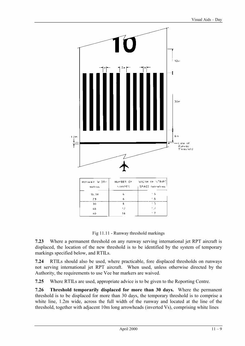
7.19 The permanent, or permanently displaced, threshold is to be indicated by a line, 1.2m wide, painted white and extending the full width of the runway at the location of the threshold, and `piano key' markings, consisting of adjacent, uniformly-spaced, white-painted, 30m long, longitudinal stripes of specified width, as shown in Fig 11.11 (next page). This marking should also be used to indicate permanent, or permanently displaced, threshold at gravel and natural surfaced runways.
7.20 Information on the location of thresholds is provided in Chapter 7.
Temporarily displaced threshold markings
7.21 Whenever a permanent threshold is temporarily displaced, a new system of visual cues must be provided, which may include the provision of new markings, the obscuring and alteration of existing markings, and the use of CASA approved Runway Threshold Identification Lights (RTILs).
Note: RTIL details are given in Chapter 20.
7.22 Where a threshold is temporarily displaced less than 300m from the end of the runway, there is no additional survey requirement for obstacles. However, where a threshold is to be displaced more than 300m from the end of the runway, the aerodrome licence holder is to refer the matter to the Authority.
Note: Landing aids such as T-VASIS and ILS will be affected by the temporary relocation of a threshold.
Visual Aids – Day
April 2000 11 – 9
Fig 11.11 - Runway threshold markings
7.23 Where a permanent threshold on any runway serving international jet RPT aircraft is displaced, the location of the new threshold is to be identified by the system of temporary markings specified below, and RTILs.
7.24 RTILs should also be used, where practicable, fore displaced thresholds on runways not serving international jet RPT aircraft. When used, unless otherwise directed by the Authority, the requirements to use Vee bar markers are waived.
7.25 Where RTILs are used, appropriate advice is to be given to the Reporting Centre.
7.26 Threshold temporarily displaced for more than 30 days. Where the permanent threshold is to be displaced for more than 30 days, the temporary threshold is to comprise a white line, 1.2m wide, across the full width of the runway and located at the line of the threshold, together with adjacent 10m long arrowheads (inverted Vs), comprising white lines

Rules and Practices for Aerodromes Chapter 11
11 – 10 April 2000
1.2m wide. The existing runway centreline markings between the two thresholds are to be converted to arrows. The permanent threshold marking and associated runway designation number are to be obscured and a temporary runway designation number is to be provided 12m from the new threshold, as shown in Fig 11.12.
Fig 11.12 - Temporarily displaced threshold markings (more than 30 days
7.27 Threshold temporarily displaced for more than 5 days but not more than 30 days, or by more than 450m. The new location is to be indicated by “Vee-bar” markers comprising gable markers painted white and positioned on each side of the runway together with flush, white, arrow markings, as shown in Fig 11.13, and the existing threshold markings are to be obscured. For runways more than 18m wide, or accommodating RPT service aircraft, 2 gables and 2 arrows are to be provided on each side of the runway. In other cases a single gable and arrow on each side of the runway may be used.

Visual Aids – Day
November 2000 11 – 11
Fig 11.13 - Temporarily displaced threshold markings (less than 30 days)
7.28 Threshold temporarily displaced for 5 days or less. Where a threshold is to be temporarily displaced for 5 days or less, and the displacement is less than 450m, the new threshold location is to be indicated by the markings shown in Fig. 11.13 but the permanent thresholds markings may be retained.
7.29 Where a threshold at an air traffic controlled aerodrome is to be temporarily displaced for 5 days or less, and the displacement is more than 450 m, the new threshold location is to be indicated by the markings shown in Fig 11.13 but the permanent threshold markings may be retained.

Rules and Practices for Aerodromes Chapter 11
11 – 12 November 2000
7.30 Markings of typical thresholds and displaced thresholds are illustrated in Figs 11.14 (a), (b), (c), (d), (e) and (f).
Fig 11.14 (a) - Markings for a typical runway with the threshold at the runway end
Fig 11.14 (b) - Markings for a typical runway with a permanently displaced threshold