chapter four - airport studymonterey.airportstudy.com/files/2012/12/df-ch4.pdf · parallel taxiway...
TRANSCRIPT

Now that existing capacities and projected demands have been established, the spe¬ci ic types and quantities of facilities needed to adequately serve projected demand levels can be identi ied. This chapter addresses air ield (i.e., runways, taxiways, naviga¬tional aids, marking and lighting, and support facilities) and landside (i.e., passenger terminal building, cargo buildings, general aviation terminal facilities, hangars, aircraft parking apron, support facilities) facil¬ity requirements based on the analysis completed in Chapters Two and Three.
The objective of this effort is to identify, in general terms, the adequacy of the existing facilities and outline what and when new facilities may be needed, to accommodate the forecast demands. Having established these facility requirements, alternatives for providing these facilities will be evaluated in Chapter Five - Alternatives to assess the most cost-effective and ef icient means for implementation.
AIRFIELD REQUIREMENTS
Airport facilities include both air ield and landside components that are related to the arrival, departure, and ground movement of aircraft. These components include:
• Runway Design Standards• Runway Design Components• Taxiway Design Standards • Navigational Approach Aids• Lighting, Marking, and Signage
4-1
Chapter FourChapter FourChapter Four
Draft Final -June 2015

MASTER PLAN – Monterey Regional Airport
FACILITY REQUIREMENTS 4-2 DRAFT FINAL – JUNE 2015
RUNWAY DESIGN STANDARDS The FAA has established several imaginary surfaces to protect aircraft operational areas and keep them free from obstructions. These include the runway safety area (RSA), run-way object free area (ROFA), runway obstacle free zone (ROFZ), and runway protection zone (RPZ). In addition, standards for separation of facilities and aircraft have been estab-lished. Exhibit 4A presents the runway design standards as they apply to Monterey Re-gional Airport. The entire RSA, ROFA, and ROFZ must be under the direct ownership of the airport sponsor to ensure these areas remain free of obstacles and can be readily accessed by maintenance and emergency personnel. RPZs should also be under airport ownership. Alternatives to outright ownership of the RPZ are the purchase of avigation easements (acquiring control of designated airspace within the RPZ) or having sufficient land use control measures in places to ensure the RPZ remains free of incompatible development. Dimensional standards for the various safety areas associated with the runways are a func-tion of the type of aircraft using or expected to use the runways as well as the instrument approach capability. The Runway Design Code (RDC) for each runway defines the appro-priate design standards. As identified in Chapter Two – Forecasts, the RDC for Primary Runway 10R-28L is D-III-2400 and for Parallel Runway 10L-28R it is B-I-1A. Exhibit 4B depicts the current conditions related to the various safety areas associated with the runway system at the Airport. Runway Safety Area (RSA) The RSA is defined in FAA Advisory Circular (AC) 150/5300-13A, Airport Design, as a “sur-face surrounding the runway prepared or suitable for reducing the risk of damage to air-planes in the event of undershoot, overshoot, or excursion from the runway.” The RSA is centered on the runway and dimensioned in accordance to the approach speed of the criti-cal design aircraft using the runway. The FAA requires the RSA to be cleared and graded, drained by grading or storm sewers, capable of accommodating the design aircraft and fire and rescue vehicles, and free of obstacles not fixed by navigational purpose such as runway edge lights or approach lights. The FAA has placed a high significance on maintaining adequate RSA at all airports. Under Order 5200.8, effective October 1, 1999, the FAA established the Runway Safety Area Pro-gram. The Order states, “The objective of the Runway Safety Area Program is that all RSAs at federally-obligated airports…shall conform to the standards contained in Advisory Circu-lar 150/5300-13(A), Airport Design, to the extent practicable,” by December 31, 2015. The standard for the primary runway is an RSA measuring 500 feet wide and providing 1,000 feet beyond the departure end. On the approach end, at least 600 feet is required. Prior to the current RSA Project, the primary runway did not fully meet the design stand-ards beyond the ends of the runway.

Design Aircraft D-III-4 B-I-1A (small)Example Aircraft MD-88 King Air 200Runway Design Code (RDC) D-III-2400 B-I-5000 (small)Approach Reference Code (APRC) B-I-2400 B-I-5000 (small)Departure Reference Code (DPRC) B-II B-I (small)Visibility Minimums ½-Mile (10R)/1-Mile(28L) 1¼-MileRUNWAY DESIGN Runway Width 150 60Runway Shoulder Width 25 10RUNWAY PROTECTION Runway Safety Area (RSA)¹ Width 5002 120 Length Beyond Departure End 1,000 240 Length Prior to Threshold 600 240Runway Object Free Area (ROFA) Width 800 250 Length Beyond Departure End 1,000 240 Length Prior to Threshold 600 240Runway Obstacle Free Zone (ROFZ) Width 400 250 Length Beyond End 200 200Precision Obstacle Free Zone (POFZ) Width 800 NA Length 200 NAApproach Runway Protection Zone (RPZ) Length 2,500 (10R) / 1,700 (28L) 1,000 Inner Width 1,000 (10R) / 1,000 (28L) 250 Outer Width 1,700 (10R) / 1,510 (28L) 450Departure Runway Protection Zone (RPZ) Length 1,700 1,000 Inner Width 500 250 Outer Width 1,010 450RUNWAY SEPARATION Runway Centerline to: Parallel Runway3 700 (500) Same Holding Position 250 (200) 125 Parallel Taxiway 400 (275)4 150 Aircraft Parking Area 500 (330) 125
Design Aircraft is comprised of the Aircraft Approach Category (AAC), the Airplane Design Group (ADG), and the Taxiway Design Group (TDG). RDC is comprised of the AAC, the ADG, and the Runway Visibility Range (RVR). APRC is comprised of the AAC, ADG, and RVR and is based on the existing runway/taxiway separation. DPRC is comprised of the AAC and ADG and is based on the existing runway/taxiway separation.
¹ Upon completion of the RSA Project, RSA beyond the runway ends will meet standard.2 Hold lines on taxiways F,G,H, and K are within the RSA south of Runway 10R-28L. 3 For simultaneous visual operations (does not consider wake turbulence). 4 At its narrowest point, Taxiway A is 275 feet from the runway.
All dimensions in feetBOLD TYPE indicates current condition.
Source: FAA AC 150/5300-13A, Airport Design
Runway 10R-28L Runway 10L-28R
Exhibit 4ARUNWAY DESIGN STANDARDS

0 1000 2000
SCALE IN FEET
NORTH
xxxxxxxxxxxxxx
xxx
xxxxxxxxxxxxxx
xxx
218
ARRIVAL RPZ
DEPARTURE RPZ
EMAS 390’ x 170’WITH 35’ LEAD-IN
ARRIVAL RPZ
68
Monterey Salinas HighwayMonterey Salinas Highway
Garden Rd.
Garden Rd.
68
N. Fremont St.
N. Fremont St.Cabr
illo
Hig
hway
Cabr
illo
Hig
hway
EMAS 390’ x 170’WITH 35’ LEAD-IN
DEPARTURE RPZ
35’35’
425’425’425’
35’35’
Runway 10R-28LRunway 10R-28L
Runway 10L-28R
300’
500’500’
327.5’327.5’275’275’
800’500’
327’327’
390’390’ 390’390’
’’ 88888888
150’
200’22222222222222222250’120’ 22
Exhibit 4BSAFETY AREAS
E
F
B
A
G
G
J K
H J K L
L
N
N
C M
E
D
LEGENDAirport Property Line
Runway Protection Zone (RPZ)
Departure RPZ
Runway Safety Area (RSA)
Object Free Area (OFA)
Obstacle Free Zone (OFZ)
Precision Obstacle Free Zone(POFZ)
To Be Removed
Retaining Wall
Engineered Materials Arresting System (EMAS)
xxxxxxxxxx

MASTER PLAN – Monterey Regional Airport
FACILITY REQUIREMENTS 4-3 DRAFT FINAL – JUNE 2015
The current RSA Project at the Airport is intended to provide 100 percent compliance with RSA standard at each end of Runway 10R-28L. The project will include installation of engi-neered materials arresting system (EMAS) at both runway ends. This system of crushable concrete is capable of stopping an aircraft overrun with minimal aircraft damage. As de-signed, EMAS provides the equivalency of a standard RSA. For this Master Plan study, the RSAs beyond the primary runway ends are considered to meet design standards as the pro-ject is currently underway. The RSA design standard width for primary Runway 10R-28L is 500 feet as centered on the runway. This standard is met and should be maintained. The RSA may be penetrated by aircraft under the following current conditions:
a. Between Taxiways E and K, Taxiway A is 275 feet from the runway centerline. Therefore, any aircraft taxiing on Taxiway A with a wingspan greater than 50 feet (25 feet to each side) will encroach into the RSA.
b. The airport design aircraft falls in ADG-III (wingspans up to 118 feet). When these aircraft are taxiing on Taxiway A (between Taxiways F and K), their wings will pene-trate the RSA by up to 34 feet.
c. The hold lines for Taxiways F, G, H, and K are 200 feet from the runway centerline, placing them and holding aircraft within the RSA.
Currently, the Airport and airport traffic control tower (ATCT) implement special operating procedures in order to reduce the potential for encroachment into the RSA during active use of the runway. This includes limiting the type of aircraft that can operate on Taxiway A when the runway is in use by aircraft in AAC C or greater. The Alternatives chapter will present options to mitigate the potential for penetration of the RSA. The hold lines for Taxiways F, G, J, and K, are situated within the RSA (but outside the OFZ) because of a lack of runway to taxiway separation. The Alternatives chapter will also exam-ine options to relocate the hold lines outside the RSA. The RSA standard for parallel Runway 10L-28R is 120 feet wide extending 240 feet beyond the runway end. This standard is met and should be maintained. Runway Object Free Area (ROFA) The ROFA is “a two-dimensional ground area, surrounding runways, taxiways, and tax-ilanes, which is clear of objects except for objects whose location is fixed by function (i.e., airfield lighting).” The ROFA does not have to be graded and level like the RSA; instead, the primary requirement for the ROFA is that no object in the ROFA penetrates the lateral ele-vation of the RSA. The ROFA is centered on the runway, extending out in accordance to the critical design aircraft utilizing the runway. The current ROFA standard for the primary runway is 800 feet wide and extends 1,000 feet beyond the runway ends. For the parallel runway, the ROFA width standard is 250 feet and

MASTER PLAN – Monterey Regional Airport
FACILITY REQUIREMENTS 4-4 DRAFT FINAL – JUNE 2015
extends 240 feet beyond the runway ends. The ROFA standards are met for both runways and should be maintained. Runway Obstacle Free Zone (ROFZ) The ROFZ is an imaginary volume of airspace which precludes object penetrations, includ-ing taxiing and parked aircraft. The only allowance for ROFZ obstructions is navigational aids mounted on frangible bases which are fixed in their location by function, such as air-field signs. The ROFZ is established to ensure the safety of aircraft operations. If the ROFZ is obstructed, the airport’s approaches could be removed or approach minimums could be increased. The ROFZ for the primary runway is 400 feet wide and extends 200 feet beyond the run-way ends. The ROFZ for the parallel runway is 250 feet wide and extends 200 feet beyond the runway end. This design standard is met for both runways at the Airport and should be maintained. A precision obstacle free zone (POFZ) is further defined for runway ends with a precision approach, such as the instrument landing system (ILS) approach to Runway 10R. The POFZ is 800 feet wide and extends from the runway threshold a distance of 200 feet. The POFZ is in effect when the following conditions are met:
a) The runway supports a vertically guided approach; b) Reported ceiling is below 250 feet and/or visibility is less than ¾-mile; and c) An aircraft is on final approach within two miles of the runway threshold.
When the POFZ is in effect, a wing of an aircraft holding on a taxiway may penetrate the POFZ; however, neither the fuselage nor the tail may infringe on the POFZ. The POFZ standard is met at the Airport and should be maintained. Runway Protection Zones (RPZ) The RPZ is a trapezoidal area centered on the runway, typically beginning 200 feet beyond the runway end. The RPZ has been established by the FAA to provide an area clear of ob-structions and incompatible land uses in order to enhance the protection of people and property on the ground. The dimensions of the RPZ vary according to the visibility mini-mums serving the runway and the type of aircraft (design aircraft) operating on the run-way. While the RPZ is intended to be clear of incompatible objects or land uses, some uses are permitted with conditions and other land uses are prohibited. According to AC 159/5300-13A, Airport Design, the following land uses are permissible within the RPZ:
• Farming that meets the minimum buffer requirements; • Irrigation channels as long as they do not attract birds;

MASTER PLAN – Monterey Regional Airport
FACILITY REQUIREMENTS 4-5 DRAFT FINAL – JUNE 2015
• Airport service roads, as long as they are not public roads and are directly con-trolled by the airport operator;
• Underground facilities, as long as they meet other design criteria, such as RSA re-quirements, as applicable; and
• Unstaffed navigational aids (NAVAIDs) and facilities, such as required for airport fa-cilities that are fixed-by-function in regard to the RPZ.
Any other land uses considered within RPZ land owned by the airport sponsor must be evaluated and approved by the FAA Office of Airports. The FAA has published Interim Guidance on Land Uses within a Runway Protection Zone (Interim Guidance; dated Septem-ber 27, 2012), which identifies several potential land uses that must be evaluated and ap-proved prior to implementation. The specific land uses requiring FAA evaluation and ap-proval include:
• Buildings and structures including , but are not limited to: - Residences - Schools - Churches - Hospitals or other medical care facilities - Commercial/industrial buildings
• Recreational land use (examples include, but are not limited to: golf courses, sports fields, amusement parks, other places of public assembly, etc.)
• Transportation facilities. Examples include, but are not limited to: - Rail facilities - light or heavy, passenger or freight
- Public roads/highways - Vehicular parking facilities • Fuel storage facilities (above and below ground) • Hazardous material storage (above and below ground) • Wastewater treatment facilities • Above-ground utility infrastructure (i.e., electrical substations), including any type
of solar panel installations. The Interim Guidance states, “RPZ land use compatibility also is often complicated by own-ership considerations. Airport owner control over the RPZ land is emphasized to achieve the desired protection of people and property on the ground. Although the FAA recognizes that in certain situations the airport sponsor may not fully control land within the RPZ, the FAA expects airport sponsors to take all possible measures to protect against and remove or mitigate incompatible land uses.” Currently, the RPZ review standards are applicable to any new or modified RPZ. The fol-lowing actions or events could alter the size of an RPZ, potentially introducing an incom-patibility:
• An airfield project (e.g., runway extension, runway shift); • A change in the critical design aircraft that increases the RPZ dimensions; • A new or revised instrument approach procedure that increases the size of the RPZ;
and/or • A local development proposal in the RPZ (either new or reconfigured).

MASTER PLAN – Monterey Regional Airport
FACILITY REQUIREMENTS 4-6 DRAFT FINAL – JUNE 2015
The Interim Guidance only addresses the introduction of new or modified land uses to an RPZ and proposed changes to the RPZ size or location. Airport sponsors must continue to remove or mitigate the risk of any existing incompatible land uses in the RPZ as practical. While it is still necessary for the airport sponsor to take all reasonable actions to meet the RPZ design standard, FAA funding priority for certain actions, such as relocating existing roads or acquiring property in the RPZ, are determined on a case-by-case basis. The approach RPZs serving Runways 10R, 28L, and 28R extend beyond Airport property and include incompatibilities such as commercial buildings. The approach RPZ serving Runway 10L is entirely on Airport property and meets design standards. As there are existing incompatibilities within three of the four approach RPZs, the Airport and FAA should pursue opportunities to acquire and remove any incompatibilities. Runway Separation Standards Federal standards are in place to provide adequate separation between the runway center-line and other elements such as parallel runways, taxiways, hold lines, and fixed or mova-ble objects. Parallel Runway Separation The minimum standard for the separation of parallel runways is 700 feet, which permits simultaneous visual operations. The runways at the Airport currently are separated by on-ly 500 feet. The parallel runway system provides several benefits to the Airport. First, it provides for the opportunity to separate small and large aircraft to a greater extent. Second, it reduces the number of operations on the primary runway, thus reducing wear and tear and poten-tially extending its useful life. Third, the parallel runway helps the Airport maintain its commitment to accommodating general aviation activity. As mentioned previously, the Alternatives chapter will consider the future disposition of the parallel runway. Parallel Taxiway Separation The design standard for the separation between runways and parallel taxiways is a func-tion of the critical design aircraft and the instrument approach visibility minimum. The separation standard for RDC D-III aircraft with ½-mile visibility minimums is 400 feet from the runway centerline to the parallel taxiway centerline. Taxiway A is separated by 327 feet on the west end, 327.5 feet on the east end, and by 275 feet nearest the terminal area. Taxiway B, on the north side of the primary runway, is 300 feet from the runway.

MASTER PLAN – Monterey Regional Airport
FACILITY REQUIREMENTS 4-7 DRAFT FINAL – JUNE 2015
The lack of standard separation distance between the runway and Taxiway A has been ad-dressed by the FAA in the past. A conditional waiver for the Taxiway A separation was ap-proved on August 4, 1976 (and reaffirmed on June 19, 1978), provided the Airport imple-ment operating procedures to limit use of Taxiway A by large aircraft (B-737 or larger) when another large aircraft is operating on the runway. These procedures have been im-plemented. For Taxiway B, a request for a modification to standard was suggested but has not been implemented as of this writing in 2014. The separation standard for parallel Runway 10L-28R and parallel taxiways is 125 feet centerline to centerline. Taxiway C is situated 150 feet from the runway and Taxiway B is 200 feet from the runway. Both meet separation standard and should be maintained. The Alternatives chapter will evaluate potential solutions to meeting separation standards between Runway 10R-28L and Taxiways A and B. Hold Line Separation The standard hold line position leading to primary Runway 10R-28L is 250 feet from the runway centerline. The hold lines on Taxiways F, G, J, and K (south of the runway) are cur-rently positioned at 200 feet from the runway centerline. The hold lines on Taxiways A (thresholds), L, and N (south of the primary runway) are positioned at a separation dis-tance of 250 feet. The hold lines north of the runway are 250 feet from the runway center-line. Potential options to meet the standard for hold line position will be examined in the Alternatives chapter. The hold line standard for parallel Runway 10L-28R is 125 feet from the runway center-line. This standard is met and should be maintained. Aircraft Parking Area The design standard for separation between the centerline of primary Runway 10R-28L and aircraft parking areas is 500 feet. On the south side of the runway, the aircraft parking areas are 330 feet from the runway centerline, thus not meeting standard. This will be ad-dressed in the Alternatives chapter. The design standard for separation of aircraft parking areas and parallel Runway 10L-28R is 125 feet. The closest parking area is approximately 270 feet from the runway centerline; thus, the standard is met and should be maintained. RUNWAY DESIGN COMPONENTS The adequacy of the existing runway at the Airport has been analyzed from a number of perspectives, including runway orientation, runway length, runway width, and pavement

MASTER PLAN – Monterey Regional Airport
FACILITY REQUIREMENTS 4-8 DRAFT FINAL – JUNE 2015
strength. This information will identify the adequacy of the runway system and indicate if improvements to the runway system are necessary. Runway Orientation The Airport is currently served by a parallel runway system. Primary Runway 10R-28L is currently 7,603 feet long and 150 feet wide. Following completion of the RSA Project cur-rently under construction, the primary runway will measure 7,175 feet in length with 7,000 feet available for landing in both directions. Analysis related to the primary runway as-sumes that the RSA Project has been completed. Parallel Runway 10L-28R is 3,504 feet long, 60 feet wide, and is 500 feet north of the eastern portion of the primary runway (cen-terline to centerline). Key considerations in the runway configuration of an airport involve the orientation for wind coverage and the operational capacity of the runway system. FAA AC 150/5300-13A, Airport Design, recommends that a crosswind runway should be made available when the primary runway orientation provides less than 95 percent wind coverage for any aircraft forecast to use the airport on a regular basis. The 95 percent wind coverage is computed on the basis of the crosswind component not exceeding 10.5 knots (12 mph) for RDC A/B-I, 13 knots (15 mph) for RDC A/B-II, and 16 knots (18 mph) for RDC A/B-III, C/D-I through C/D-III, and 20 knots (23 mph) for RDC C-III through D-IV. Weather data specific to the airport was obtained from the National Oceanic and Atmos-pheric Administration’s (NOAA) National Climatic Data Center. This data was collected from the on-field automated surface observing system (ASOS) over a continuous 10-year period from 2004 to 2013. A total of 121,131 observations of wind direction and other da-ta points were made. The parallel runways provide 98.57 percent wind coverage for 10.5 knot crosswinds, 99.35 percent coverage at 13 knots, and 99.87 percent at 16 knots. In instrument flight condi-tions (visibility less than three miles and/or cloud ceilings lower than 1,000 feet), the run-way orientation provides for greater than 95 percent wind coverage for each crosswind component. Exhibit 4C presents both the all-weather and instrument flight rules (IFR) wind rose for the Airport. Future Runway Configuration Primary Runway 10R-28L is planned to remain in its current configuration which provides for greater than 95 percent wind coverage, thus meeting FAA standards. Parallel Runway 10L-28R serves an important role as the general aviation training runway; however, it is separated from the primary runway by 500 feet which means it does not provide the capacity benefit that parallel runways are typically intended to do. For exam-ple, a parallel runway system with 700 feet of separation would provide up to a 40 percent

Exhibit 4CWINDROSE

MASTER PLAN – Monterey Regional Airport
FACILITY REQUIREMENTS 4-9 DRAFT FINAL – JUNE 2015
increase in overall capacity. The following two options will be considered in the Alterna-tives chapter:
• Maintaining the runway in its current location; or • Relocating the runway to a separation distance of at least 700.
Runway Length AC 150/5325-4B, Runway Length Requirements for Airport Design, provides guidance for determining runway length needs. A draft revision of this AC is currently available (150/5325-4C) and the FAA is utilizing the draft revision in most cases when evaluating runway length needs for airports. The primary difference between the two ACs is that the current AC provides a general runway length recommendation for business jets weighing more than 12,500 pounds, and the new draft AC requires use of individual aircraft perfor-mance charts published by the manufacturer for all aircraft weighing more than 12,500 pounds. This runway length analysis will consider the recommendations from both ver-sions. Aircraft performance capability is a key factor in determining the runway length needed for takeoff and landing. The performance capability and, subsequently, the runway length re-quirement of a given aircraft type can be affected by five primary factors:
• Mean maximum temperature of the hottest month • Airport elevation • Runway gradient • Critical aircraft type expected to use the runway (design aircraft) • Stage length of the longest non-stop destination (specific to larger aircraft)
The mean maximum daily temperature of the hottest month for Monterey Regional Airport is 69.3 degrees Fahrenheit (F), which occurs in September. The airport elevation is 257 feet above mean sea level (MSL). The change in elevation (gradient) varies by 98.9 feet from the east end (high point) to the west end (low point), providing a runway gradient of 1.4 percent. The design aircraft for primary Runway 10R-28L is classified as D-III-4, which is best represented by the Boeing MD-80 series aircraft (MD-88) in use by Allegiant Air. The design aircraft for parallel Runway 10L-28R is B-I-1A, which is best represented by single and multi-engine piston aircraft weighing less than 12,500 pounds. There is not a direct relationship between the classification of the design aircraft (e.g., B-I, D-III) and runway length as airplanes operate on a wide variety of available runway lengths. The suitability of the runway length is governed by many factors, including eleva-tion, temperature, wind, aircraft weight, wing flap settings, runway condition (wet or dry), runway gradient, vicinity airspace obstructions, useful load, and any special operating pro-cedures. The aircraft load is dependent upon the payload of passengers and/or cargo, plus the amount of fuel it has on board. For departures, the amount of fuel varies depending upon

MASTER PLAN – Monterey Regional Airport
FACILITY REQUIREMENTS 4-10 DRAFT FINAL – JUNE 2015
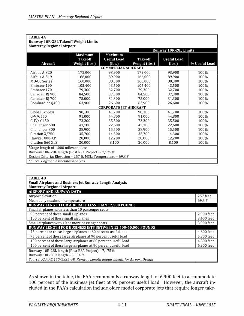
the length of non-stop flight or trip length. As of February 2014, the longest daily non-stop commercial flight was to Denver (834 nautical miles) operated by United using a 50-seat CRJ aircraft. The current (May 12, 2015) longest length is the daily flight to Phoenix which is 518 nautical miles. According to recorded flight plans for 2013 accessed at AirportIQ.com, corporate jet air-craft regularly conduct non-stop operations to east coast destinations such as Teterboro (2,230 nautical miles), Westchester County (2,244 nautical miles), Philadelphia (2,187 nau-tical miles), and Baltimore (2,129 nautical miles). Aircraft conducting these trips include the Bombardier Global Express, Falcon 900/2000, Cessna Citation 750, and Gulfstream 400/500/550 business jet aircraft. Flight plans also reflect non-stop destinations to Hawaii (2,000 nautical miles) and Alaska (1,800 nautical miles). The Airport should have the capability to handle the most demanding aircraft with regards to runway length. Thus, the following discussion considers the most demanding runway length requirements now and in the future. Airport sponsors can pursue policies that can maximize the suitability of the runway length. Policies, such as area zoning and height and hazard restrictions, can protect an air-port’s runway length. Airport ownership (fee simple or easement) of land leading to the runway ends can reduce the possibility of natural growth or man-made obstructions. Planning of runways should include an evaluation of aircraft types expected to use the air-port, or a particular runway now and in the future. Future plans should be realistic and supported by the FAA-approved forecasts and should be based on the critical design air-craft (or family of aircraft). Runway 10R-28L is the primary runway intended to accommodate the critical design air-craft. The performance charts for passenger aircraft and business jets utilizing (or those likely to utilize) the Airport were considered. Table 4A outlines the weight restrictions for key commercial and corporate jet aircraft which may be expected to operate on Runway 10R-28L. Following completion of the RSA Project, the effective length of Runway 10R-28L will be 7,175 feet, with 7,000 feet available for landing in each direction. As shown in the table, most aircraft can operate on Runway 10R-28L at this length with 100 percent useful load (fuel and payload). The MD-80 series aircraft does not have a useful load limitation until non-stop stage lengths exceed 1,000 nautical miles. With only limited payload reduc-tion, it is capable of a 2,000 nautical mile stage length. Most other non-stop U.S. destina-tions which may be considered by airlines or businesses in the future will be capable of op-erating without restricted payloads. As mentioned, FAA AC 150/5325-4B provides general runway length requirements for two categories of aircraft: those weighing less than 12,500 pounds (i.e., small aircraft), and those business jets weighing between 12,500 and 60,000 pounds. Table 4B presents this analysis when applying conditions specific to the Airport.
MASTER PLAN – Monterey Regional Airport
FACILITY REQUIREMENTS 4-11 DRAFT FINAL – JUNE 2015
TABLE 4A Runway 10R-28L Takeoff Weight Limits
Monterey Regional Airport
Runway 10R-28L Limits
Aircraft
Maximum Takeoff
Weight (lbs.)
Maximum Useful Load
(lbs.) Takeoff
Weight (lbs.) Useful Load
(lbs.) % Useful Load COMMERCIAL AIRCRAFT
Airbus A-320 172,000 93,900 172,000 93,900 100% Airbus A-319 166,000 89,900 166,000 89,900 100% MD-80 Series¹ 160,000 80,300 160,000 80,300 100% Embraer 190 105,400 43,500 105,400 43,500 100% Embraer 170 79,300 32,700 79,300 32,700 100% Canadair RJ 900 84,500 37,300 84,500 37,300 100% Canadair RJ 700 75,000 31,300 75,000 31,300 100% Bombardier Q400 63,900 26,600 63,900 26,600 100%
CORPORATE JET AIRCRAFT Global Express 98,100 41,700 98,100 41,700 100% G-V/G550 91,000 44,800 91,000 44,800 100% G-IV/ G450 73,200 35,500 73,200 35,500 100% Challenger 600 43,100 22,600 43,100 22,600 100% Challenger 300 38,900 15,500 38,900 15,500 100% Citation X/750 35,700 14,300 35,700 14,300 100% Hawker 800-XP 28,000 12,200 28,000 12,200 100% Citation 560 XLS 20,000 8,100 20,000 8,100 100% ¹Stage length of 1,000 miles and less. Runway 10R-28L length (Post RSA Project) – 7,175 ft.
Design Criteria: Elevation – 257 ft. MSL; Temperature – 69.3 F. Source: Coffman Associates analysis TABLE 4B Small Airplane and Business Jet Runway Length Analysis Monterey Regional Airport AIRPORT AND RUNWAY DATA Airport elevation 257 feet Mean daily maximum temperature 69.3 F RUNWAY LENGTH FOR AIRCRAFT LESS THAN 12,500 POUNDS Small airplanes with less than 10 passenger seats: 95 percent of these small airplanes 2,900 feet 100 percent of these small airplanes 3,400 feet Small airplanes with 10 or more passenger seats 3,900 feet RUNWAY LENGTH FOR BUSINESS JETS BETWEEN 12,500-60,000 POUNDS 75 percent or these large airplanes at 60 percent useful load 4,600 feet 75 percent of these large airplanes at 90 percent useful load 5,800 feet 100 percent of these large airplanes at 60 percent useful load 4,800 feet 100 percent of these large airplanes at 90 percent useful load 6,900 feet Runway 10R-28L length (Post RSA Project) – 7,175 ft. Runway 10L-28R length – 3,504 ft. Source: FAA AC 150/5325-4B, Runway Length Requirements for Airport Design
As shown in the table, the FAA recommends a runway length of 6,900 feet to accommodate 100 percent of the business jet fleet at 90 percent useful load. However, the aircraft in-cluded in the FAA’s calculation include older model corporate jets that require longer take-

MASTER PLAN – Monterey Regional Airport
FACILITY REQUIREMENTS 4-12 DRAFT FINAL – JUNE 2015
off runway lengths, which are gradually being phased out of the national active fleet mix. It is for this reason that the FAA has published the new draft AC which recommends consult-ing the individual aircraft performance charts. Runway 10R-28L’s ultimate length of 7,175 feet is adequate for the commercial and corpo-rate jets anticipated to use the Airport through the planning period. According to FAA AC 150/5325-4B, Runway Length Requirements for Airport Design, paral-lel general aviation runways should be designed for the critical aircraft anticipated to use the secondary runway. In the case of Monterey Regional Airport, the majority of aircraft that utilize the parallel runway are exclusively small general aviation aircraft weighing less than 12,500 pounds. The recommended runway lengths for small airplanes were calculat-ed utilizing the runway length curve charts in AC 150/5325-4B and are outlined in Table 4B. As shown in the table, the existing runway length of Runway 10L-28R (3,504 feet) meets the FAA recommended runway length for small aircraft with less than 10 seats. A 400-foot extension would be necessary to accommodate small aircraft with 10 or more passenger seats. The airfield capacity analysis completed in Chapter Three – Demand/Capacity did not indicate a need to increase the role of this runway to accommodate an additional class of aircraft (small with 10+ passenger seats). This runway is best suited for training and touch-and-go operations. Other factors, such as the non-standard separation between the runways (which will be discussed later in this chapter) lead to the conclusion that this runway, if it is to be maintained, should remain at its current length. Runway Length Summary Primary Runway 10R-28L is the appropriate length to accommodate the current and future critical design aircraft for the Airport. As shown, the runway length does not limit the use-ful load of most commercial aircraft using or likely to use the runway. All business jets are capable of operating without weight restrictions. Therefore, the current length of the run-way (7,175 feet after the RSA Project is complete) is appropriate and should be maintained. Parallel Runway 10L-28R is capable of accommodating all small aircraft operations; how-ever, some with 10 or more passenger seats may be weight-restricted. This runway is in-tended to accommodate small itinerant aircraft and local training operations. There is not a capacity need to extend the runway. Therefore, it is recommended that this runway re-main at its current length. In the Alternatives chapter, other possibilities will be examined such as relocating the runway (to meet separation standard) or closing the runway. Runway Width The width of the runway is a function of the airplane design group (ADG) for each runway. The standard width is 150 and 60 feet for primary Runway 10R-28L and parallel Runway 10L-28R, respectively. Both runways currently meet standard and should be maintained at their current width.

MASTER PLAN – Monterey Regional Airport
FACILITY REQUIREMENTS 4-13 DRAFT FINAL – JUNE 2015
Runway Strength An important feature of airfield pavement is its ability to withstand repeated use by air-craft. Primary Runway 10R-28L is strength-rated at 100,000 pounds for single wheel loads (SWL), 160,000 pounds for dual-wheel loads, and 300,000 pounds for dual-tandem wheel loads (DTWL). Parallel Runway 10L-28R is strength-rated at 12,500 pounds SWL. The strength rating for both runways is adequate and should be maintained. Line of Sight and Gradient FAA has instituted various line of sight requirements to facilitate coordination among air-craft and between aircraft and vehicles that are operating on active runways. This allows departing and arriving aircraft to verify the location and actions of other aircraft and vehi-cles on the ground that could create a conflict. Line of sight standards for an individual runway are based on whether there is a parallel taxiway available. If a parallel taxiway is available, thus facilitating faster runway exit times, then any point five feet above the runway centerline must be mutually visible, with any other point five feet above the runway centerline that is located at a distance of less than half the length of the runway. If a parallel taxiway is not available, then these points must be mutually visible over the length of the entire runway. Both runways meet the line of sight standard, which should be maintained. The runway gradient is the maximum allowable slope for a runway. For primary Runway 10R-28L the standard is no more than 1.5 percent. The runway slopes upward from the west to the east at a grade of 1.4 percent. The maximum allowable gradient for parallel Runway 10L-29R is 2.0 percent. The gradient is 1.7 percent. Both runways meet gradient standard, which should be maintained. TAXIWAY DESIGN STANDARDS The design standards associated with taxiways are determined by the taxiway design group (TDG) and the airplane design group (ADG) of the critical design aircraft that would potentially use that taxiway. Table 4C presents the various taxiway design standards to be applied at the Airport.

MASTER PLAN – Monterey Regional Airport
FACILITY REQUIREMENTS 4-14 DRAFT FINAL – JUNE 2015
TABLE 4C Taxiway Design Standards
Parallel Runway
10L-28R Primary Runway
10R-28L STANDARDS BASED ON WINGSPAN (ADG) ADG I ADG III
Taxiway Protection Taxiway Safety Area (TSA) width 49' 118' Taxiway Object Free Area (TOFA) width 89' 186' Taxilane Object Free Area width 79' 162'
Taxiway Separation Taxiway Centerline to: Parallel Taxiway/Taxilane 70' 152' Fixed or Movable Object 44.5' 93' Taxilane Centerline to: Parallel Taxilane 64' 140' Fixed or Movable Object 39.5' 81'
Wingtip Clearance Taxiway Wingtip Clearance 20' 34' Taxilane Wingtip Clearance 15' 27' STANDARDS BASED ON TDG 1A/1B TDG 3/4 Taxiway Width Standard 25' 50' Taxiway Edge Safety Margin 5' 10' Taxiway Shoulder Width 10' 20' ADG: Airplane Design Group TDG: Taxiway Design Group
Source: FAA AC 150/5300-13A, Airport Design Taxiway Width Standards The design aircraft for the Airport and for primary Runway 10R-28L falls in classification D-III-4; therefore, the taxiways that may potentially support aircraft within TDG-4 should be at least 50 feet wide. Taxiways associated with a design aircraft in TDG-1A, such as those exclusively associated with parallel Runway 10L-28R, should be at least 25 feet wide. Table 1J previously outlined the various widths of taxiways at the Airport. Taxiways serv-ing the primary runway range between 50 and 75 feet in width. The taxiways on the north side of the parallel runway are all 20 feet wide. Any potential changes to the width of existing taxiways will be considered in the Alterna-tives chapter. Any new taxiways should be planned at standard widths. Other Taxiway Design Considerations FAA AC 150/5300-13A, Airport Design, provides guidance on taxiway design that has a goal of enhancing safety by providing a taxiway geometry that reduces the potential for runway incursions. A runway incursion is defined as, “any occurrence at an airport involving the incorrect presence of an aircraft, vehicle, or person on the protected area of a surface des-ignated for the landing and takeoff of aircraft.”

MASTER PLAN – Monterey Regional Airport
FACILITY REQUIREMENTS 4-15 DRAFT FINAL – JUNE 2015
The following is a list of the taxiway design guidelines and the basic rationale behind each recommendation: 1. Taxi Method: Taxiways are designed for “cockpit over centerline” taxiing, with
pavement being sufficiently wide to allow a certain amount of wander. On turns, sufficient pavement should be provided to maintain the edge safety margin from the landing gear. When constructing new taxiways, upgrading existing intersections should be undertaken to eliminate judgmental over-steering which is when the pilot must intentionally steer the cockpit outside the marked centerline in order to assure the aircraft remains on the taxiway pavement.
2. Steering Angle: Taxiways should be designed such that the nose gear steering an-
gle is no more than 50 degrees, the generally accepted value to prevent excessive tire scrubbing.
3. Three-Node Concept: To maintain pilot situational awareness, taxiway intersec-tions should provide a pilot a maximum of three choices of travel. Ideally, these are right and left angle turns and a continuation straight ahead.
4. Intersection Angles: Design turns to be 90 degrees wherever possible. For acute
angle intersections, standard angles of 30, 45, 60, 120, 135, and 150 degrees are preferred.
5. Runway Incursions: Design taxiways to reduce the probability of runway incur-
sions. - Increase Pilot Situational Awareness: A pilot who knows where he/she is on the air-
port is less likely to enter a runway improperly. Complexity leads to confusion. Keep taxiway systems simple using the “three node” concept.
- Avoid Wide Expanses of Pavement: Wide pavements require placement of signs far from a pilot’s eye. This is especially critical at runway entrance points. Where a wide expanse of pavement is necessary, avoid direct access to a runway.
- Limit Runway Crossings: The taxiway layout can reduce the opportunity for human error. The benefits are twofold – through simple reduction in the number of occur-rences, and through a reduction in air traffic controller workload.
- Avoid “High Energy” Intersections: These are intersections in the middle third of runways. By limiting runway crossings to the first and last thirds of the runway, the portion of the runway where a pilot can least maneuver to avoid a collision is kept clear.
- Increase Visibility: Right angle intersections, both between taxiways and runways, provide the best visibility. Acute angle runway exits provide for greater efficiency in runway usage, but should not be used as runway entrance or crossing points. A right angle turn at the end of a parallel taxiway is a clear indication of approaching a runway.
- Avoid “Dual Purpose” Pavements: Runways used as taxiways and taxiways used as runways can lead to confusion. A runway should always be clearly identified as a runway and only a runway.

MASTER PLAN – Monterey Regional Airport
FACILITY REQUIREMENTS 4-16 DRAFT FINAL – JUNE 2015
- Indirect Access: Do not design taxiways to lead directly from an apron to a runway. Such configurations can lead to confusion when a pilot typically expects to encoun-ter a parallel taxiway.
- Hot Spots: Confusing intersections near runways are more likely to contribute to runway incursions. These intersections must be redesigned when the associated runway is subject to reconstruction or rehabilitation. Other hot spots should be cor-rected as soon as practicable.
6. Runway/Taxiway Intersections:
- Right Angle: Right angle intersections are the standard for all runway/taxiway in-tersections, except where there is a need for a high-speed exit. Right angle taxiways provide the best visual perspective to a pilot approaching an intersection with the runway to observe aircraft in both the left and right directions. They also provide optimal orientation of the runway holding position signs so they are visible to pilots.
- Acute Angle: Acute angles should not be larger than 45 degrees from the runway centerline. A 30-degree taxiway layout should be reserved for high-speed exits. The use of multiple intersecting taxiways with acute angles creates pilot confusion and improper positioning of taxiway signage.
- Large Expanses of Pavement: Taxiways must never coincide with the intersection of two runways. Taxiway configurations with multiple taxiway and runway intersec-tions in a single area create large expanses of pavement, making it difficult to pro-vide proper signage, marking, and lighting.
7. Taxiway/Runway/Apron Incursion Prevention: Apron locations that allow di-
rect access into a runway should be avoided. Increase pilot situational awareness by designing taxiways in such a manner that forces pilots to consciously make turns. Taxiways originating from aprons and forming a straight line across runways at mid-span should be avoided.
- Wide Throat Taxiways: Wide throat taxiway entrances should be avoided. Such large expanses of pavement may cause pilot confusion and makes lighting and marking more difficult.
- Direct Access from Apron to a Runway: Avoid taxiway connectors that cross over a parallel taxiway and directly onto a runway. Consider a staggered taxiway layout that forces pilots to make a conscious decision to turn.
- Apron to Parallel Taxiway End: Avoid direct connection from an apron to a parallel taxiway at the end of a runway.
FAA AC 150/5300-13A, Airport Design, states that, “existing taxiway geometry should be improved whenever feasible, with emphasis on designated hot spots. To the extent practi-cable, the removal of existing pavement may be necessary to correct confusing layouts.” There are several taxiways at the Airport that are of concern which are identified on Exhib-it 4D. Table 4D describes those taxiway areas.

68
Monterey Salinas HighwayMonterey Salinas Highway
Canyon Del Rey Blvd.
Canyon Del Rey Blvd.
Olm
sted Rd.
Olm
sted Rd.
Skypark Dr.
Skypark Dr.
Skypark Dr.
Skypark Dr.
Airport Rd.
Airport Rd.Euclid
Ave.
Euclid Ave.
Garden Rd.
Garden Rd.
Fred Kane Dr.Fred Kane Dr.
68
N. Fremont St.
N. Fremont St.
Runway 10R - 28L ’
Airport TrafficControl Tower
Runway 10L - 28R 150’
200’500’
327.5’327’
300’
275’
218
Airport Rd.
Airport Rd.
D
E
E
B
C
A
D
K
KJGF
G
JH K
L
L
L
M N
N1
2
3
4
G5 6
K7
10
9
811
High-energy middle third of Runway
Identifier Taxiway Description of ConcernWide expanse of pavement.Converging of two taxiways at runway entrance.Direct access to runway from apron.
2 E Direct access to runway from apron.3 F Direct access to runway from apron.4 G Direct access to runway from apron.5 G Direct access to runway from apron.
Direct access to runway from apron.Mid-runway high-energy crossing.Direct access to runway from apron.Mid-runway high-energy crossing.
8 A Not at 90 degree threshold entrance taxiway.9 M Direct access to runway from apron.
10 K Not at 90 degree threshold entrance taxiway.
Source: Coffman Associates utilizing FAA AC 150/5300-13A, Airport Design
E
6 J
7 K
1
LEGENDAirport Property LineArea of ConcernEngineered Materials Arrestor System (EMAS)To Be Removed
Photo Source: Google Earth 5-6-2012
0 800 1600
SCALE IN FEET
NORTH
11 A/N Line-of-sight issue for tower.
Exhibit 4DTAXIWAY AREAS OF CONCERN
1

MASTER PLAN – Monterey Regional Airport
FACILITY REQUIREMENTS 4-17 DRAFT FINAL – JUNE 2015
TABLE 4D Taxiway Areas of Concern Monterey Regional Airport
Identifier Taxiway Description of Concern
1 E Wide expanse of pavement. Converging of two taxiways at runway entrance. Direct access to runway from apron.
2 E Direct access to runway from apron. 3 F Direct access to runway from apron. 4 G Direct access to runway from apron. 5 G Direct access to runway from apron.
6 J Direct access to runway from apron. Mid-runway high-energy crossing.
7 K Direct access to runway from apron. Mid-runway high-energy crossing.
8 A Not at 90 degree threshold entrance taxiway. 9 M Direct access to runway from apron.
10 K Not at 90 degree threshold entrance taxiway. 11 A/N Line-of-sight issue for tower.
Source: Coffman Associates utilizing FAA AC 150/5300-13A, Airport Design The Alternatives chapter will examine possible taxiway geometry changes that would im-prove pilot situational awareness and reduce potential pilot confusion. Any changes will consider the reasonableness of each alternative in terms of cost and benefit. Taxilane Design Considerations Taxilanes are distinguished from taxiways in that they do not provide access to or from the runway system directly. Taxilanes typically provide access to hangar areas. As a result, taxilanes can be constructed to varying design standards depending on the type of aircraft utilizing the taxilane. For example, a taxilane leading to a T-hangar area only needs to be designed to accommodate those aircraft typically accessing a T-hangar. The taxilanes at the Airport are those pavements between hangars. Any future taxilanes will be considered in the Alternatives chapter and will be planned to the appropriate de-sign standard. INSTRUMENT NAVIGATIONAL AIDS Instrumentation for runways is important when weather conditions are less than visual (greater than three-mile visibility and 1,000-foot cloud ceilings). Instrumentation can be classified as precision, nonprecision, and visual. The Airport has a sophisticated precision ILS (CAT-I) instrument approach to Runway 10R. This approach provides for visibility minimums as low as ½-mile and cloud ceilings down to 287 feet. The combination of a glide slope antenna, localizer antenna, and approach

MASTER PLAN – Monterey Regional Airport
FACILITY REQUIREMENTS 4-18 DRAFT FINAL – JUNE 2015
lighting system form the ILS. The ILS provides near all-weather capability for the Airport and should be maintained. The instrument approach to Runway 28L with the lowest visibility minimum is the Re-quired Navigation Performance (RNP) approach which provides 1-mile visibility with 254-foot cloud ceilings. Because winds are predominantly from the west to the east, especially in poor weather conditions, an ILS approach to Runway 28L has been considered in the past; however, the terrain to the east of the Airport has precluded this possibility. In addi-tion, an ILS would require an approach lighting system that would be expensive to install because of the steep terrain drop at the end of the runway and the commercial center at the bottom of the hill. As a result, an ILS is not considered in the future for Runway 28L. The current RNP instrument approach should be maintained. Advancements in GPS technology could lead to lower minimums for approaches to Runway 28L. Localizer Performance with Vertical Guidance (LPV) and RNP approaches are reach-ing ¾-mile visibility minimums currently. In the future, these types of approaches may provide for ½-mile visibility minimums. In the Alternatives chapter, consideration will be given to the possibility of ½-mile visibility minimums. Parallel Runway 10L-28R has non-precision instrument approaches to both runway ends. These are available for use by operators of small aircraft only (those in AAC A and B). The lowest minimums are 1¼-mile and 1,010-foot cloud ceilings. If a pilot needs better mini-mums, they can utilize the primary runway; thereby the existing instrument approaches to the parallel runway are adequate and should be maintained. VISUAL NAVIGATION AIDS The airport beacon is located on top of the ATCT. It should be maintained. If the ATCT were to be relocated, then additional consideration should be given to co-locating the bea-con with it; however, there is no requirement that the beacon be located on the ATCT. Upon completion of the RSA Project, both ends of Runway 10R-28L will be equipped with precision approach path indicator lights (PAPI-4L). These visual approach aids are ade-quate and should be maintained. Parallel Runway 10L-28R does not have any visual aids currently. Because of the variable weather conditions, especially the frequent foggy condi-tions, PAPI-2L will be considered for this runway. Runway end identification lights (REILs) are strobe lights set to either side of the runway. These lights provide rapid identification of the runway threshold. REILs should be in-stalled at runway ends not currently providing an approach lighting system but supporting instrument operations. Typically these runways support jet aircraft and have a strength rating greater than 12,500 pounds. Runway 28L is currently equipped with REILs. This system should be maintained.

MASTER PLAN – Monterey Regional Airport
FACILITY REQUIREMENTS 4-19 DRAFT FINAL – JUNE 2015
WEATHER AND COMMUNICATION AIDS Monterey Regional Airport has three primary windsocks strategically located for the great-est pilot visibility. These wind indicators should be maintained. Monterey Regional Airport is equipped with an Automated Surface Observing System (ASOS). This is an important system that automatically records weather conditions, such as wind speed, wind gust, wind direction, temperature, dew point, altimeter setting, visibil-ity, fog/haze condition, precipitation, and cloud height. This information is then transmit-ted at regular intervals. Aircraft in the vicinity can receive this information if they have their radio tuned to the correct frequency. In addition, pilots and individuals can call a published telephone number and receive the information via an automated voice record-ing. This system should be maintained through the planning period. The Airport has an FAA owned and operated ATCT which is open from 6:00 a.m. to 9:00 p.m. daily. The tower staff provide important safety functions and a tower should be main-tained. The tower at the Airport does not meet various standards for these facilities including the Americans with Disabilities Act (ADA) standards. There is also a line-of-sight issue in that tower personnel cannot see aircraft holding on the apron located at the east end of Taxiway A. Ultimately, the tower may need to be replaced by the FAA. The current Airport Layout Plan (ALP) for the Airport identifies a future location on the northeast side of the Airport. This location will be re-examined during the Alternatives analysis to determine if it is still the best location for a replacement tower. AIR CARGO REQUIREMENTS The primary cargo-related facilities requiring analysis include the cargo apron, sort build-ing space, and staging area (delivery truck and vehicle parking). Currently, there is no ded-icated cargo sort facility. The air cargo operators, West Air/FedEx and Martin Aire/UPS utilize apron areas located at the southeast corner of the general aviation apron/hangar area and on the southwest apron near the fuel farm, to load/unload directly from delivery trucks onto the aircraft. Both operators utilize smaller commuter single engine turboprop aircraft (Cessna Caravan). The cargo apron area requirements are based on the current and projected aircraft type to be utilized in air cargo service at the Airport. As presented in the Forecasts chapter, no sig-nificant change from the current use of the Cessna Caravan type of aircraft is anticipated; however, a modest increase in the number of flights is projected. Apron space require-ments are estimated at 800 square yards per Cessna Caravan; therefore, a current need ex-ists for 1,600 square yards of apron space. Estimates of the appropriate size of an air cargo sort facility are based upon national indus-try standards and range between 1.0 and 2.5 square feet per enplaned ton. For planning purposes, 2.0 square feet per ton is utilized, which results in a current need for a 1,124

MASTER PLAN – Monterey Regional Airport
FACILITY REQUIREMENTS 4-20 DRAFT FINAL – JUNE 2015
square-foot facility. By the long term, a 1,339 square-foot sort facility is projected to be needed. To accommodate the loading and unloading of aircraft, additional space is necessary for the movement of delivery trucks and equipment. This space is called the staging area and is measured in acres and is estimated at three times the forecast building size. Table 4E pre-sents the requirements needed to fully accommodate air cargo activity at the Airport. TABLE 4E Air Cargo Facility Requirements
Monterey Regional Airport
Available Short Term Intermediate
Term Long Term Enplaned Cargo (lbs.) 1,021,856 1,124,000 1,196,000 1,339,000 Cargo Apron (s.y.) 1,000 1,600 1,600 1,600 Cargo Building (s.f.) NA 1,124 1,196 1,339 Staging Area (acres) 0.02 0.05 0.06 0.06 Assumptions: Apron: 800 s.y. per Cessna Caravan (typ.)
Building: 1 s.f. per 1,000 enplaned pounds
Staging Area: 3x building size Source: Coffman Associates GENERAL AVIATION FACILITIES General aviation facilities are those necessary to accommodate airport activity by all avia-tion segments except commercial passenger service. This includes recreational flying, business aviation, charter, military, and some portions of air cargo and air ambulance activ-ity. These airport users require a variety of services, such as fueling, terminal services, maintenance, and aircraft storage. The primary components considered for general avia-tion needs include:
• Aircraft Hangars • Aircraft Parking Aprons • General Aviation Terminal Building Services • Auto Parking and Access
The future need for each of these components has been analyzed based on the aviation de-mand forecasts. AIRCRAFT HANGARS Utilization of hangar space varies as a function of local climate, security, and owner prefer-ences. The trend in general aviation, whether single or multi-engine aircraft, is toward more sophisticated aircraft (and, consequently, more expensive aircraft); therefore, many

MASTER PLAN – Monterey Regional Airport
FACILITY REQUIREMENTS 4-21 DRAFT FINAL – JUNE 2015
aircraft owners prefer enclosed hangar space to outside tie-downs. This is especially true in the region because of the corrosive nature of the frequent marine layers. The demand for aircraft storage hangars is dependent upon the number and type of aircraft expected to be based at an airport in the future. However, hangar construction should be based upon actual demand trends and financial investment conditions. While a majority of aircraft owners prefer enclosed aircraft storage, a number of based air-craft owners may still tie-down outside (due to the lack of hangar availability, hangar rental rates, and/or operational needs). Therefore, enclosed hangar facilities do not necessarily need to be planned for each based aircraft. At Monterey Regional Airport, nearly all aircraft are stored in a covered facility and outside aircraft tie-down storage is typically temporary. For planning purposes, 95 percent of based aircraft are considered to be permanently housed in an enclosed hangar. There are three general types of aircraft storage hangars: T-hangars, box hangars, and con-ventional hangars. T-hangars are similar in size and will typically house a single engine piston-powered aircraft. Some multi-engine aircraft owners may elect to utilize these facil-ities as well. There are typically many T-hangar units “nested” within a single structure. Port-a-Port hangars are considered within the T-hangar discussion. There are 50 T-hangar units at the Airport, encompassing an estimated 71,900 square feet of floor space. For de-termining future aircraft storage needs, a planning standard of 1,200 square feet per based aircraft is utilized for T-hangars. Box hangars are open-space facilities with no interfering supporting structure. Box hang-ars can vary in size and can either be attached to others or be standalone hangars. Typical-ly, box hangars will house larger multi-engine, turboprop, or jet aircraft. At the Airport, there are numerous box hangars with estimated space for 73 aircraft and a total of approx-imately 161,500 square feet of floor space. For future planning, a standard of 2,500 square feet per aircraft is utilized for box hangars. Conventional hangars are the familiar large hangars with open floor plans that can store several aircraft. It is estimated that the conventional hangars can accommodate a total of 71 aircraft and provides 181,400 square feet of floor space. Table 4F presents aircraft storage needs based on the demand forecasts. Assumptions have been made on owner preferences for a hangar type based on trends within the gen-eral aviation segment. All turboprops, business jets, and helicopters are assumed to be stored in box or conventional hangars. T-hangars are assumed to house single engine pis-ton aircraft and a small portion of multi-engine piston aircraft. It is estimated that there is a current total of 414,800 square feet of hangar storage space. The projections indicate that there is enough aircraft storage space at the Airport to ac-commodate the forecast growth in based aircraft. The projected mix of hangar space indi-cates that there may be a need for additional T-hangar space to meet typical owner prefer-ences.

MASTER PLAN – Monterey Regional Airport
FACILITY REQUIREMENTS 4-22 DRAFT FINAL – JUNE 2015
TABLE 4F Hangar Storage Needs
Monterey Regional Airport
Current Supply
Short Term
Intermediate Term Long Term
Total Need Less Current Supply
Based Aircraft 152 160 175 200 Aircraft to be Hangared 144 152 166 190 46 T-Hangar Positions 50 50 66 86 36 Box Hangar Positions 73 56 54 52 -21 Conventional Hangar Positions 71 46 47 52 -19 Hangar Area Requirements T-Hangar Area 71,900 60,000 79,000 103,000 31,100 Box Hangar Area 161,500 140,000 135,000 131,000 -30,500 Conventional Hangar Area 181,400 115,000 116,000 130,000 -51,400 Total Storage Area (s.f.) 414,800 315,000 330,000 364,000 -50,800 Source: Coffman Associates analysis. The analysis indicates that the existing supply of box and conventional hangar space is ad-equate through the long term planning period. Hangar requirements are general in nature and are based on standard hangar size esti-mates and typical user preferences. If a private developer desires to construct or lease a large hangar to house one plane, any extra space in that hangar may not be available for other aircraft. The actual hangar area needs will be dependent on the usage within each hangar. GENERAL AVIATION AIRCRAFT APRON The general aviation aircraft apron is an expanse of paved area intended for aircraft park-ing and circulation. Typically, a main apron is centrally located near the airside entry point, such as the terminal building or FBO facility. Ideally, the main apron is large enough to ac-commodate transient airport users, as well as a portion of locally based aircraft. Often, smaller aprons are available adjacent to FBO hangars and at other locations around an air-port. An aircraft parking apron should provide space for the number of locally based air-craft that are not stored in hangars, transient aircraft, and for maintenance activity. The apron layout at the Airport follows this typical pattern. Exhibit 1J previously documented the various aircraft aprons at the Airport. The northeast and southeast apron areas are considered for local aircraft tie-down needs. The northwest and southwest aprons are considered primarily for transient aircraft parking. Estimates of available spaces have been made based on current markings on the pavement. It is esti-mated there are 63 existing tie-down positions, 28 transient piston positions, and 60 tran-sient business jet positions. FAA AC 150/5300-13A, Airport Design, suggests a methodology by which transient apron requirements can be determined from knowledge of busy-day operations. At Monterey Regional Airport, the number of itinerant spaces required is estimated at 13 percent of the

MASTER PLAN – Monterey Regional Airport
FACILITY REQUIREMENTS 4-23 DRAFT FINAL – JUNE 2015
busy-day itinerant general aviation operations (122 x 0.13 = 16). This results in a current need for 16 itinerant aircraft parking spaces. Of this total, approximately 60 percent are assumed for business jets and commercial transport aircraft. The remaining 40 percent are for transient piston aircraft. A planning criterion of 800 square yards per aircraft was applied to determine future tran-sient apron area requirements for single and multi-engine aircraft. For turboprops and business jets (which can be much larger), a planning criterion of 1,600 square yards per aircraft position was used. The current need for transient apron area is estimated at 43,280 square yards. By the long term planning period, approximately 59,300 square yards is estimated to be needed. The current transient aprons encompass a total of approximately 105,400 square yards; therefore, the total transient space available appears adequate through the long term plan-ning period. Local aircraft tie-down needs are derived from the estimated number of based aircraft which will tie-down, plus an additional ten spaces. The additional spaces allow for an un-expected influx of aircraft or, more typically, for the temporary movement of aircraft into and out of hangars. It is estimated there is a current need for 18 tie-down positions and a long term forecast of 20 positions. Approximately 63 positions are available; thus, local tie-down positions are adequate through the long term. While the Airport has adequate apron area to accommodate local and transient activity, new development may require additional apron area based on business needs. In addition, several times per year, the Airport is unable to accommodate the influx of itinerant aircraft visiting the area for specific events, such as the annual Pebble Beach Professional Golf Tournament, the Concours d’Elegance, and auto racing at Laguna Seca. During these times, it is not unusual for all apron space to be occupied necessitating some aircraft to utilize other area airports. Table 4G presents the calculated aircraft apron needs for the Airport. TABLE 4G Aircraft Apron Requirements
Monterey Regional Airport
FORECAST
Currently Available
(Est)
Current Need
(2014) Short Term
Intermediate Term Long Term
Local Apron Positions 63 18 18 19 20 Local Apron Area (s.y.) 22,400 22,880 23,400 24,400 26,000 Transient Apron Positions
Piston 28 6 7 8 10 Business Jet 60 10 11 12 16 Total Transient Positions 88 16 18 20 26 Transient Apron Area (s.y.)
Piston 10,000 5,100 5,900 6,500 8,000 Business Jet 95,400 15,300 17,700 19,600 25,300 Total Transient Apron Area (s.y.) 105,400 20,400 23,600 26,100 33,300 Total Apron Area (s.y) 127,800 43,280 47,000 50,500 59,300 Source: Coffman Associates analysis
MASTER PLAN – Monterey Regional Airport
FACILITY REQUIREMENTS 4-24 DRAFT FINAL – JUNE 2015
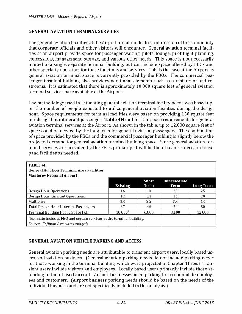
GENERAL AVIATION TERMINAL SERVICES The general aviation facilities at the Airport are often the first impression of the community that corporate officials and other visitors will encounter. General aviation terminal facili-ties at an airport provide space for passenger waiting, pilots’ lounge, pilot flight planning, concessions, management, storage, and various other needs. This space is not necessarily limited to a single, separate terminal building, but can include space offered by FBOs and other specialty operators for these functions and services. This is the case at the Airport as general aviation terminal space is currently provided by the FBOs. The commercial pas-senger terminal building also provides additional elements, such as a restaurant and re-strooms. It is estimated that there is approximately 10,000 square feet of general aviation terminal service space available at the Airport. The methodology used in estimating general aviation terminal facility needs was based up-on the number of people expected to utilize general aviation facilities during the design hour. Space requirements for terminal facilities were based on providing 150 square feet per design hour itinerant passenger. Table 4H outlines the space requirements for general aviation terminal services at the Airport. As shown in the table, up to 12,000 square feet of space could be needed by the long term for general aviation passengers. The combination of space provided by the FBOs and the commercial passenger building is slightly below the projected demand for general aviation terminal building space. Since general aviation ter-minal services are provided by the FBOs primarily, it will be their business decision to ex-pand facilities as needed. TABLE 4H General Aviation Terminal Area Facilities
Monterey Regional Airport
Existing Short Term
Intermediate Term Long Term
Design Hour Operations 16 18 20 25 Design Hour Itinerant Operations 12 14 16 20 Multiplier 3.0 3.2 3.4 4.0 Total Design Hour Itinerant Passengers 37 46 54 80 Terminal Building Public Space (s.f.) 10,000¹ 6,800 8,100 12,000 ¹Estimate includes FBO and certain services at the terminal building. Source: Coffman Associates analysis GENERAL AVIATION VEHICLE PARKING AND ACCESS General aviation parking needs are attributable to transient airport users, locally based us-ers, and aviation business. (General aviation parking needs do not include parking needs for those working in the terminal building, which were projected in Chapter Three.) Tran-sient users include visitors and employees. Locally based users primarily include those at-tending to their based aircraft. Airport businesses need parking to accommodate employ-ees and customers. (Airport business parking needs should be based on the needs of the individual business and are not specifically included in this analysis.)

MASTER PLAN – Monterey Regional Airport
FACILITY REQUIREMENTS 4-25 DRAFT FINAL – JUNE 2015
A planning standard of 3.0 times the design hour itinerant passenger count provides the minimum number of vehicle spaces needed for transient users. The multiplier represents an average number of passengers on a general aviation aircraft. Locally based parking spaces are calculated as one-half the number of based aircraft. And, a planning standard of 315 square feet per space is utilized to determine total vehicle parking area necessary, which includes area needed for circulation and handicap clearances. Parking requirements for the Airport are summarized in Table 4J. TABLE 4J GA Vehicle Parking Requirements
Monterey Regional Airport
Current Need Short Term Intermediate
Term Long Term Design Hour Itinerant Passengers 37 46 54 80 VEHICLE PARKING SPACES GA Itinerant Spaces 71 86 102 152 GA Based Spaces 76 80 88 100 Airport Business/Office Parking Spaces Individual Business Decision Total Parking Spaces 147 166 190 252 VEHICLE PARKING AREA GA Itinerant Parking Area (s.f.) 22,400 27,000 32,000 48,000 GA Based Parking Area (s.f.) 23,900 25,000 28,000 32,000 Airport Business Parking Area (s.f.) Individual Business Decision Total Parking Area (s.f.) 46,300 52,000 60,000 80,000 Source: Coffman Associates analysis
The challenge with general aviation vehicle parking is that it should be in close proximity to airport services or to an aircraft owner’s hangar. In an effort to limit the level of vehicle traffic on the aircraft movement areas, many airports provide separate parking in support of facilities with multiple aircraft parking positions, such as T-hangars. Vehicle parking spaces will be considered in conjunction with additional facility needs in the Alternatives chapter. Access to general aviation services and hangars should be segregated to the greatest extent possible from access to the commercial terminal complex. Generally, this access is appro-priately separated at the Airport. Access to the southeast apron area is via Olmsted Way. Access to the southwest apron is via Skypark Drive. Access to the northwest and northeast apron areas is via Airport Road. None of these require drivers to pass in front of the termi-nal building. Any new general aviation facilities will be planned to be accessed without adding additional congestion to the passenger terminal complex. Some users of general aviation facilities must drive on the secure side of the airfield, par-ticularly owners of locally based aircraft. Access onto the airfield is strictly limited to au-thorized personnel in accordance with FAR Part 139 standards. Those general aviation us-ers needing to pass through a gate are appropriately badged.

MASTER PLAN – Monterey Regional Airport
FACILITY REQUIREMENTS 4-26 DRAFT FINAL – JUNE 2015
AIRPORT SUPPORT REQUIREMENTS Various facilities that do not logically fall within classifications of airside or landside facili-ties have also been identified. These other areas provide certain functions related to the overall operation of the Airport. AIRCRAFT RESCUE AND FIREFIGHTING (ARFF) FACILITIES Part 139 airports, such as Monterey Regional Airport, are required to provide aircraft res-cue and firefighting (ARFF) services during commercial air carrier operations. The Airport maintains a fleet of ARFF vehicles to respond to Airport emergencies. Current equipment and firefighting agents meet ARFF Index B as required. The ARFF Index level is not antici-pated to change through the planning period. One of the fire trucks is approaching the end of its useful life and should be replaced in a timely manner. The current ARFF building is outdated and does not meet modern design standards for such facilities. In addition, the ARFF building is located only 560 feet from the primary runway centerline, making it an obstruction to the FAR Part 77 Transitional surface. For these reasons, considerations will be given to the location of a replacement ARFF building in the Alternatives chapter. FUEL STORAGE As discussed in Chapter One – Inventory, fuel sales and delivery to aircraft is managed by the FBOs on the Airport. There is a total capacity of 88,000 gallons of storage capacity for Jet A fuel and 37,750 for AvGas. Additional fuel storage capacity should be planned when the Airport is unable to maintain an adequate supply and reserve. While each airport (or FBO) determines their own desired reserve, a 14-day reserve is common for AvGas fuel and a seven-day supply is common for Jet A. When additional capacity is needed, it should be planned in 10,000- to 12,000-gallon increments, which can accommodate common fuel tanker trucks that typically have an 8,000-gallon capacity. The projections for fuel demand are based primarily on the forecast growth in aviation ac-tivity. By the long term planning period, it is estimated that 5.8 million gallons of Jet A and 204,000 gallons of AvGas will be sold annually. When calculating a 7-day reserve, Jet A storage capacity of 112,000 is required and 8,000 gallons for AvGas is required. Additional Jet A fuel storage is needed in the short term, while AvGas fuel storage is adequate through the long term. Table 4K presents the forecast fuel demand for the Airport.

MASTER PLAN – Monterey Regional Airport
FACILITY REQUIREMENTS 4-27 DRAFT FINAL – JUNE 2015
TABLE 4K Fuel Storage Requirements
Monterey Regional Airport
Planning Horizon
Current Capacity
Baseline Consumption* Short Term
Intermediate Term Long Term
Jet A Requirements 88,000 Annual Usage (gal.) 4,362,000 4,736,000 5,072,000 5,817,000 Daily Usage (gal.) 11,951 12,975 13,896 15,937 7-Day Storage (gal.) 83,885 91,077 97,538 111,865 Avgas Requirements 37,750 Annual Usage (gal.) 153,000 166,000 178,000 204,000 Daily Usage (gal.) 419 455 488 559 14-Day Storage (gal.) 5,885 6,367 6,827 7,825 *Reflects an eight-year average of fuel delivered to aircraft including commercial aircraft. Projected growth based on operations growth forecast Source: Airport fuel sales records; Coffman Associates analysis AIRPORT MAINTENANCE FACILITIES The Airport maintains various apparatus needed for the maintenance of the Airport’s facili-ties. This equipment should be maintained in good working order. Replacement of older equipment should be scheduled at regular intervals. It is desirable to provide a single maintenance facility building or complex in order to consolidate these functions. Currently, maintenance buildings are separated into two locations: several small buildings immedi-ately south of Del Monte Aviation; and a hangar located on the southeast apron area. The combined size of the current facilities is approximately 4,300 square feet. Future planning in Chapter Five - Alternatives will consider potential locations for a consolidated mainte-nance building encompassing at least 5,000 square feet. PERIMETER FENCING Perimeter fencing is used at airports primarily to secure the aircraft operational area. The physical barrier of perimeter fencing provides the following functions:
• Gives notice of the legal boundary of the outermost limits of a facility or security-sensitive area.
• Assists in controlling and screening authorized entries into a secured area by deter-
ring entry elsewhere along the boundary. • Supports surveillance, detection, assessment, and other security functions by
providing a zone for installing intrusion-detection equipment and closed-circuit tel-evision (CCTV).

MASTER PLAN – Monterey Regional Airport
FACILITY REQUIREMENTS 4-28 DRAFT FINAL – JUNE 2015
• Deters casual intruders from penetrating a secured area by presenting a barrier that requires an overt action to enter.
• Demonstrates the intent of an intruder by their overt action of gaining entry. • Causes a delay to obtain access to a facility, thereby increasing the possibility of de-
tection. • Creates a psychological deterrent to potential intruders. • Optimizes the use of security personnel while enhancing the capabilities for detec-
tion and apprehension of unauthorized individuals. • Demonstrates a corporate concern for facility security. • Limits inadvertent access to the aircraft operations area by wildlife.
The Airport has perimeter fencing that meets standards for Part 139 airports. The fencing should be maintained. The current CIP for the Airport includes improvements to the pe-rimeter fencing in a manner that implements the FAA-approved Wildlife Hazard Manage-ment Plan (2013) for the Airport. INTERIOR ACCESS Service roads are typically used to segregate vehicles from aircraft operational areas and to provide access to the airfield for authorized users. At the Airport, some service roads are paved and others are gravel/dirt. In the terminal area, the aprons and taxiways are used. The segregation of vehicle and aircraft operational areas is supported by the FAA, and it is recommended that an airport operator limit vehicle operations on the movement areas of an airport to only those vehicles necessary to support the operational activity of an airport. The Airport should maintain the existing paved perimeter access roads, and segregated and marked driving lanes on aircraft aprons through the planning period. In conjunction with the current RSA project, a service road is planned around both ends of the primary runway. There is no service road east of Taxiway K, south of the Taxiway A. As a result, service vehicles typically drive on the taxiway shoulder to access areas to the east. Where feasible, dedicated service roads should be considered and planned in the Al-ternatives chapter. TERMINAL BUILDING SUMMARY The facility requirements for the passenger terminal building were presented in Chapter Three – Demand/Capacity and are shown on Exhibit 3D. Each functional space in the build-ing was analyzed to determine if the current space available is adequate under the current conditions as well as for each planning horizon level.

MASTER PLAN – Monterey Regional Airport
FACILITY REQUIREMENTS 4-29 DRAFT FINAL – JUNE 2015
Overall, the terminal building is approximately 69,000 square feet in size. The current cal-culated need is approximately 64,000 square feet meaning the size of the facility meets in-dustry standards for overall size. In the short term, corresponding with 223,000 total an-nual enplanements, approximately 72,000 square feet is projected to be needed. By the in-termediate and long term, 80,000 and then 92,000 square feet are needed respectively. While the terminal building space calculations show the current size meeting standard, by function several areas are currently undersized and may not be easily expanded or changed. In the ticket lobby functional area, for example, the queuing area in front of the ticket counters and the TSA baggage check area both show to be exceeded in the short term. In the baggage claim area both the floor area and the circulation area show to be un-dersized currently, particularly during peak periods when multiple aircraft are deplaning. Additionally, in the secure concourse area, the circulation areas are currently undersized by almost 70 percent. By the long term, the secure hold rooms are projected to be under-sized. In the concessions area, retail space is shown to be currently undersized. Rental car area is also showing an inadequate queuing area and by the intermediate term inadequate counter frontage. Also considered is administrative space, industry standards indicate that the space currently utilized for these functions is less than what is needed. The Alternatives chapter will consider improvements to the Airport’s terminal building, so that its facilities and amenities better accommodate long term projected demand. TERMINAL SEPARATION REQUIREMENTS As noted in Chapter Three – Demand/Capacity, the existing commercial apron is appropri-ately sized; however, it is long and narrow, which necessitates parallel aircraft parking for larger aircraft (including the MD-80 series, design aircraft) and operating restrictions on Taxiway A. Essentially, there is not enough depth to the aircraft apron. Further, the terminal building itself penetrates the FAR Part 77 Transitional surface, which is an imaginary airspace surface emanating from the edge of the Primary surface at a 7:1 ratio. The primary surface is 1,000 feet wide as centered on the runway, thus the transition surface begins at a distance of 500 feet from the runway centerline. The terminal building is 500 feet from the runway centerline thus it penetrates the transitional surface at its base. There is obstruction lighting in place. The Alternatives chapter will consider options to provide greater depth to the commercial apron. SUMMARY This chapter has outlined the facilities required to meet potential the aviation demand pro-jected for Monterey Regional Airport for the next 20 years. Regarding the airfield, Exhibit 4E presents a summary of the airside considerations and identifies potential improvements to the Airport that are subject to further analysis in the

MASTER PLAN – Monterey Regional Airport
FACILITY REQUIREMENTS 4-30 DRAFT FINAL – JUNE 2015
Alternatives chapter. Similarly, Exhibit 4F presents a summary of the Airport’s general aviation and support needs, highlighting in red font those facilities that would operate at a deficit in any of the Airport Master Plan’s planning periods absent further improvements to the Airport. The next chapter, Chapter Five - Alternatives, examines potential improvements to the air-field system and the landside area. Most of the discussion focuses on those capital im-provements that would be eligible for federal grant funds. Other projects of local concern also are presented on a limited basis. Several facility layouts that meet the forecast de-mands over the next 20 years are presented in Chapter Five; and, ultimately, an overall ALP that presents a long term vision will be developed.

Primary Runway 10R-28L Primary Runway 10R-28L RDC D-III-2400 Maintain 7,175' x 150' Maintain 100-S; 150-D; 300-DT Maintain Standard RSA,OFA, OFZ, POFZ Maintain RPZ Incompatibilities Remove Incompatibilities if Feasible Non-Standard Hold Lines Provide Standard Hold Lines Precision markings Maintain HIRL Maintain Parallel Runway 10L-28R Parallel Runway 10L-28R RDC B-I-5000 Maintain or Relocate 3,503' x 60' Maintain or Relocate 12.5-S Maintain or Relocate Standard RSA, OFA, OFZ Maintain or Relocate Basic marking Maintain or Relocate MIRL Maintain or Relocate RPZ Incompatibilities Remove Incompatibilities if Feasible
Runway to Runway - 500' Consider Relocation to 700' Primary Runway to Taxiway A - 275' Provide 400' to Meet Standard if Feasible Primary Runway to Taxiway B - 300' Provide 400' to Meet Standard if Feasible Primary Runway to Aircraft Parking Area - 300' Provide 500' to Meet Standard if Feasible TDG-4 (Primary Runway) Maintain Various Taxiway Widths Consider Uniform 50' Taxiway Width TDG 1A (Parallal Runway) Maintain 20' Taxiway Width Consider Uniform 25' Taxiway Width MITL Maintain Layout Deficiencies Redesign Layout ASOS, 3 lighted windsocks, Consider replacement ATCT/ Maintain Others segmented circle, beacon, ATCT Primary Runway 10R-28L Primary Runway 10R-28L ½-mile CAT-I ILS Rwy 10R Maintain 1-mile RNP (GPS) Rwy 28L Consider ¾ or ½-mile RNP Rwy 28L 1¼-mile LPV Rwy 10R Consider ¾ or ½-mile LPV Rwy 10R LOC, GPS Rwy 10R Maintain GPS, LOC/DME Rwy28L Maintain Parallel Runway 10L-28R Parallel Runway 10L-28R 1¼-mile GPS Rwy 10L Maintain 1¼-mile GPS Rwy 28R Maintain Primary Runway 10R-28L Primary Runway 10R-28L PAPI-4L Maintain MALSR (10L) Maintain REIL (Rwy 28L) Maintain Parallel Runway 10L-28R Parallel Runway 10L-28R None PAPI-2L
##-S/D/DT - Runway Strength Rating in Thousands of Pounds for Single (S), Dual (D), Dual Tandem (DT)Wheel Struts ASOS - Automated Surface Observation SystemLPV - GPS with Localizer Performance and Vertical Guidance
MALSR - Medium Intensity Approach Lighting System with Runway Alignment Indicator LightsMIRL/HIRL - Medium/High Intensity Runway Lighting MITL - Medium Intensity Taxiway Lighting OFA - Object Free Area OFZ/POFZ - Obstacle Free Zone/Precision Obstacle Free Zone
PAPI - Precision Approach Path IndicatorRDC - Runway Design CodeREIL - Runway End Identification Lights RNP - GPS with Required Navigation PerformanceRPZ - Runway Protection ZoneRSA - Runway Safety Area TDG - Taxiway Design Code
POTENTIAL IMPROVEMENTSRUNWAYSRUNWAYS
Runway to Runway - 500'P i R t T i A 275'
SEPARATION STANDARDS SEPARATION STANDARDS
TAXIWAYSTAXIWAYS
INSTRUMENT NAVIGATION AND WEATHER AIDSINSTRUMENT NAVIGATION AND WEATHER AIDS
VISUAL AIDSVISUAL AIDS
AVAILABLE
Exhibit 4EAIRSIDE REQUIREMENTS
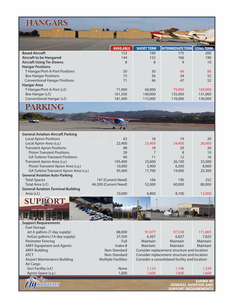
Based Aircraft 152 160 175 200Aircraft to be Hangared 144 152 166 190Aircraft Using Tie-Downs 8 8 9 10Hangar Positions T-Hangar/Port-A-Port Positions 50 50 66 86 Box Hangar Positions 73 56 54 52 Conventional Hangar Positions 71 46 47 52Hangar Area T-Hangar/Port-A-Port (s.f.) 71,900 60,000 79,000 103,000 Box Hangar (s.f.) 161,500 140,000 135,000 131,000 Conventional Hangar (s.f.) 181,400 115,000 116,000 130,000
General Aviation Aircraft Parking Local Apron Positions 63 18 19 20 Local Apron Area (s.y.) 22,400 23,400 24,400 26,000 Transient Apron Positions 88 18 20 26 Piston Transient Positions 28 7 8 10 GA Turbine Transient Positions 60 11 12 16 Transient Apron Area (s.y.) 105,400 23,600 26,100 33,300 Piston Transient Apron Area (s.y.) 10,000 5,900 6,500 8,000 GA Turbine Transient Apron Area (s.y.) 95,400 17,700 19,600 25,300General Aviation Auto Parking Total Spaces 147 (Current Need) 166 190 252 Total Area (s.f.) 46,300 (Current Need) 52,000 60,000 80,000General Aviation Terminal Building Area (s.f.) 10,000 6,800 8,100 12,000
Support Requirements Fuel Storage Jet A gallons (7-day supply) 88,000 91,077 97,538 111,865 AvGas gallons (14-day supply) 37,500 6,367 6,827 7,825 Perimeter Fencing Full Maintain Maintain Maintain ARFF Equipment and Agents Index B Maintain Maintain Maintain ARFF Building Non-Standard Consider replacement structure and location ATCT Non-Standard Consider replacement structure and location Airport Maintenance Building Multiple Facilities Consider a consolidated facility and location Air Cargo Sort Facility (s.f.) None 1,124 1,196 1,339 Apron Space (s.y.) 1,000 1,600 1,600 1,600
AVAILABLE SHORT TERM INTERMEDIATE TERM LONG TERM
Exhibit 4FGENERAL AVIATION AND
SUPPORT REQUIREMENTS