chapter four hydraulic machines contents 1- introduction...
TRANSCRIPT
Chapter Four
Hydraulic Machines Contents 1- Introduction. 2- Pumps. 3- Turbines. )لفرع الميكانيك العام فقط( 4- Cavitation in hydraulic machines. 5- Examples. 6- Problems; sheet No. 4 (Pumps) 7- Problems; sheet No. 4 (Turbines) 1- Introduction: There are two basic types of hydraulic machines:
- Pumps: these machines add energy to fluids. - Turbines: these machines convert the fluid energy into useful
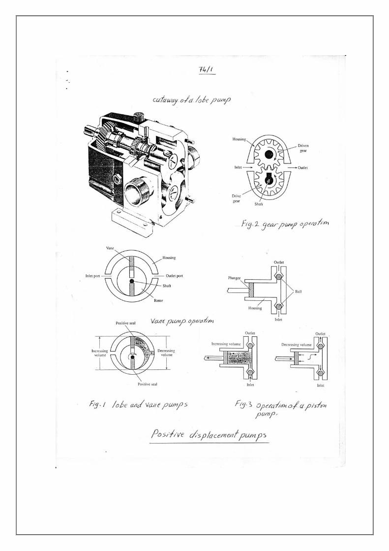
mechanical work. 2- Pumps: Pumps are used to convert mechanical energy to fluid energy. In most of the cases pumps are used for raising fluids from a lower to a higher level. This is achieved by creating a low pressure at the inlet or suction end and high pressure at the outlet or delivery end of the pump. Classification of pumps: a- Positive displacement pumps. (figures (1) through (3)) b- Rotodynamic or (dynamic pressure pumps). (figures (4) and (5)) - Centrifugal pump. - Axial pump. - mixed flow pump.

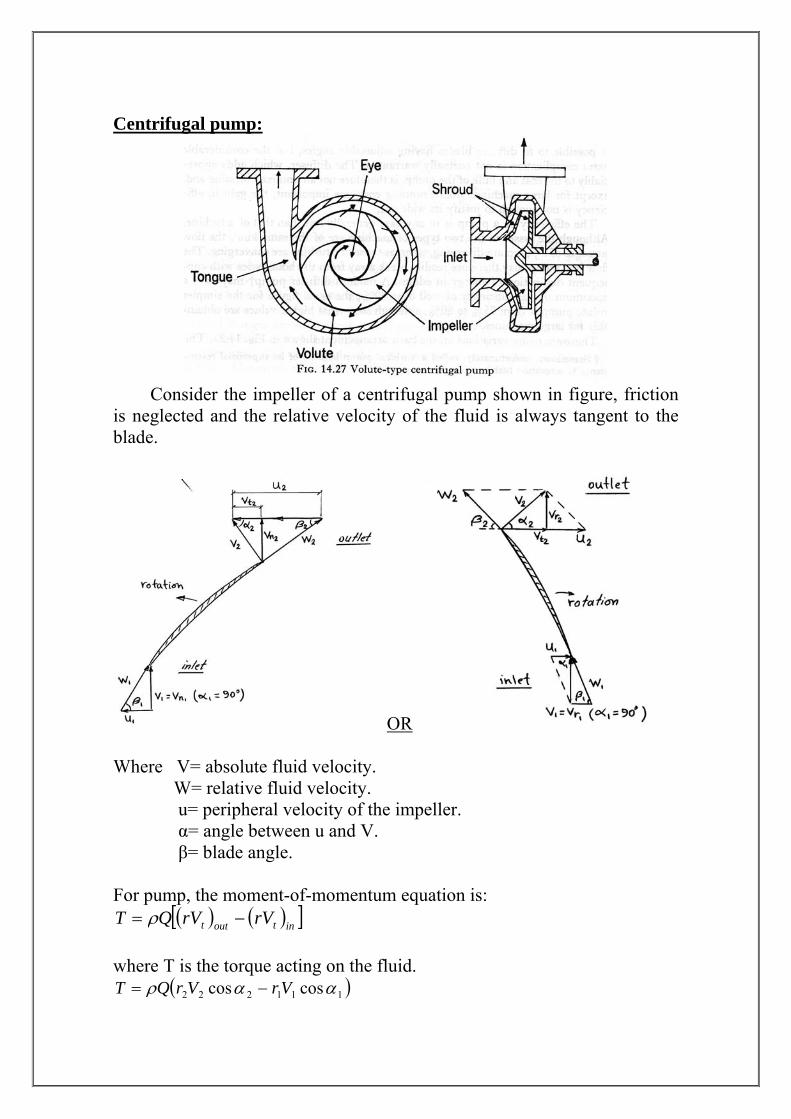
Centrifugal pump:
Consider the impeller of a centrifugal pump shown in figure, friction is neglected and the relative velocity of the fluid is always tangent to the blade.
OR Where V= absolute fluid velocity. W= relative fluid velocity. u= peripheral velocity of the impeller. α= angle between u and V. β= blade angle. For pump, the moment-of-momentum equation is:
( ) ( )[ ]intoutt rVrVQT −= ρ where T is the torque acting on the fluid.
( )111222 coscos ααρ VrVrQT −=
The power is:
( )111222 coscos ααρ VuVuQPower −= The theoretical pump head is:
gVuVu
Hth111222 coscos αα −
=
The hydraulic (or manometric) efficiency of the pump:
lossesthact
th
acth
HHHHH
−=
=
where
η
The hydraulic losses (Hlosses) include shock loss, fluid friction loss, and loss due to circulatory flow. Overall efficiency:
ωγ
ηT
QH act=
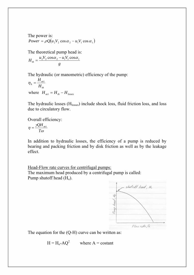
In addition to hydraulic losses, the efficiency of a pump is reduced by bearing and packing friction and by disk friction as well as by the leakage effect. Head-Flow rate curves for centrifugal pumps: The maximum head produced by a centrifugal pump is called: Pump shutoff head (Ho).
The equation for the (Q-H) curve can be written as: H = Ho-AQ2 where A = costant
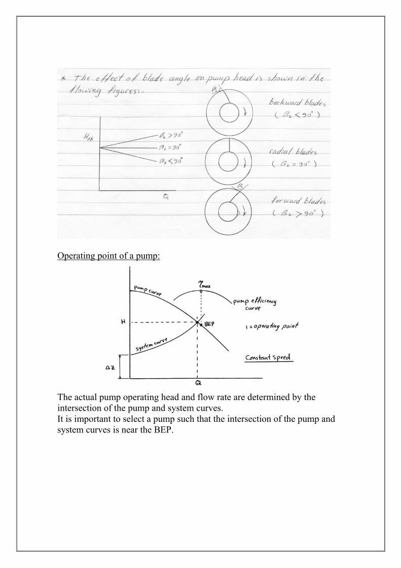
Operating point of a pump:
The actual pump operating head and flow rate are determined by the intersection of the pump and system curves. It is important to select a pump such that the intersection of the pump and system curves is near the BEP.
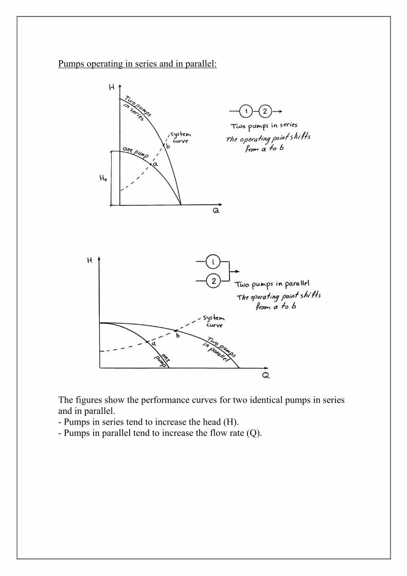
Pumps operating in series and in parallel:
The figures show the performance curves for two identical pumps in series and in parallel. - Pumps in series tend to increase the head (H). - Pumps in parallel tend to increase the flow rate (Q).
Similarity laws for centrifugal pumps:
Flow rate similarity law: pm ND
QND
Q⎟⎠⎞
⎜⎝⎛=⎟
⎠⎞
⎜⎝⎛
33
Head similarity law: pm DN
gHDN
gH⎟⎠⎞
⎜⎝⎛=⎟
⎠⎞
⎜⎝⎛
2222
Input power similarity law: pm DN
powerDN
power⎟⎟⎠
⎞⎜⎜⎝
⎛=⎟⎟
⎠
⎞⎜⎜⎝
⎛5353 ρρ
Overall efficiency similarity law: pm ηη = where: p= prototype ; m= model ; N= pump speed ; D= impeller dia. Specific speed (Ns):
In SI system: ( )4
3)(gH
QNSIN s =
where N in (rad/s) Q in (m3/s) g in (m/s2) H in (m)
In the US customary system: 43)(
H
QNUSN s =
where N in (rpm) Q in (gpm) H in (ft) The conversion factor between them is: )(2730)( SINUSN ss =
Also: 17100
)()(
USNEurN s
s =
The specific speed of a series is usually defined for the point of best efficiency (BEP). Note: when determining specific speed Ns for a multistage pump, use H1, the first stage head rather than the total head of the pump.

Multistage pumps:
General view: In multistage pumps the liquid being transferred is passed successively through several stages.
Total head H developed by n stages is: ∑=n
iHH1
where Hi = head developed by a stage. If the stages are identical then: inHH = All the impellers of the multistage pumps are similar in design. However, in some cases the first stage impeller is made with double entry to improve cavitation characteristics and increase permissible suction lift of the pump. Types of multistage pumps: 1- Multistage chamber pump. The external and axial cross sectional views of this type are shown in the following figures. An important element of this type is a guide vane assembly which passes water to the inlet of the next stage (sections A-A and B-B shown in figures). The assembly is intended to minimize hydraulic losses and ensure axial entry of the flow to the impeller (without swirling).
Multistage chamber pump, external view Guide vane assembly
Multistage chamber pump, axial cross sectional view

2- Multistage pumps with axial joint. The external and axial cross sectional views of this type are shown in the following figures. This type have a cast casing made of two halves are embodied in different ways. The liquid flow path is shown in figure.
Multistage pump with axial joint, external view
Multistage pump with axial joint, axial cross sectional view
Flow path in multistage pump with axial joint

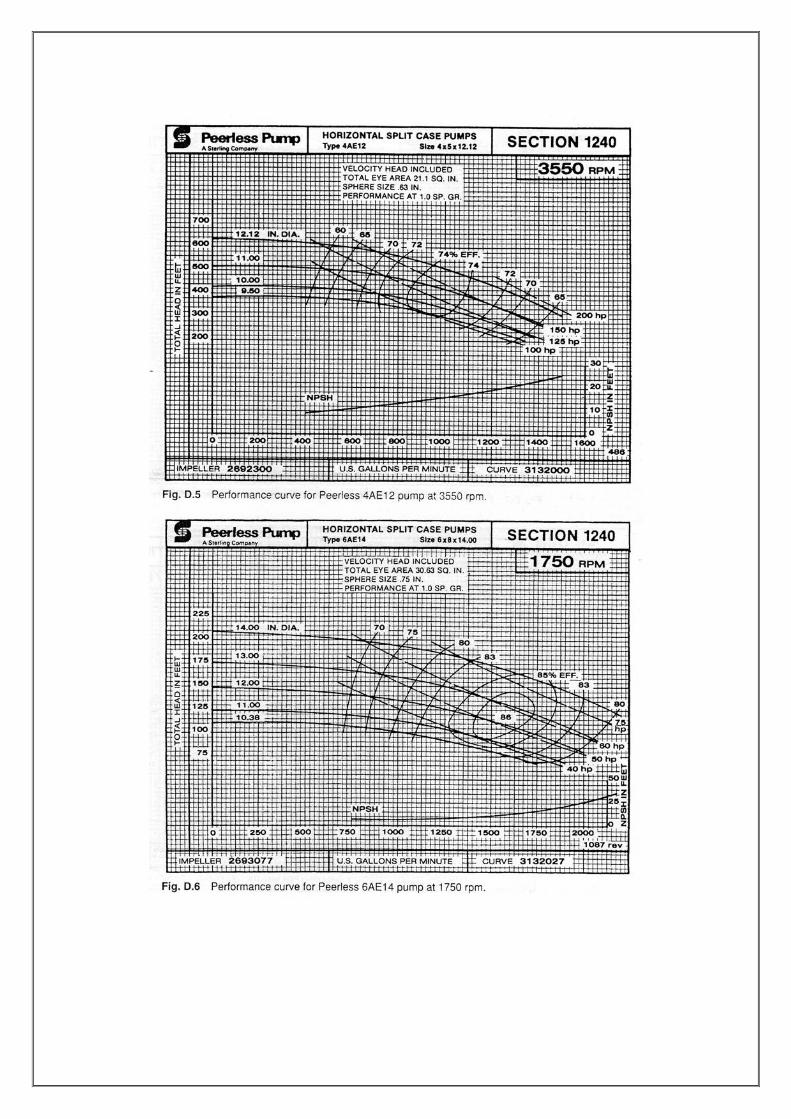
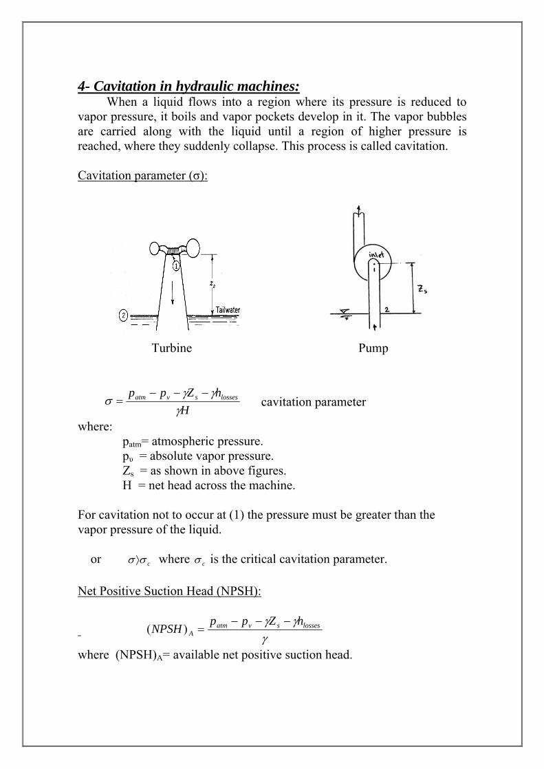
Pump selection: Each pumps manufacturer uses its own system for designating pumps. Choice of a manufacturer may be based on established practice, location, or cost. Once a manufacturer is chosen, pump selection is a four-step process as will be shown in the following example: Example: Select a pump to deliver 0.11 m3/s of water at 36.6 m total head. Choose the appropriate model and driver speed. Specify the pump efficiency, driver power, and NPSH requirement. Solution: Assume the selection is to be made from the full-line catalog of the Peerless Pump Company (USA). The required delivery and head in U.S customary system are: Q= 1750 gpm , H= 120 ft Step 1: select a pump type suited to the application. The Peerless product line catalog specifies a maximum delivery and head of 2500 gpm and 660 ft for series AE pumps. Assume the selection is to be made from this series. Step 2: use selector charts. The desired operating point is not within any pump contour on the 3500 rpm selector chart (Fig D.1). From the 1750 rpm chart (Fig D.2) select a model 6AE14 pump. From the performance curve for 6AE14 pump (Fig D.6) choose a 13 in. impeller. Step 3: use performance charts. On the performance chart for the 6AE14 pump, project up from Q=1750 gpm. Project across from H=120 ft on the ordinate. The intersection is the pump performance at the desired operating point. ( 8.85≈η % , power 64≈ hp) From the operating point, project down to the NPSH curve. At the intersection, read (NPSH)R ft. 17≈ Step 4: verify that the system operating condition has been predicted accurately and the pump has been selected correctly.


3- Turbines:
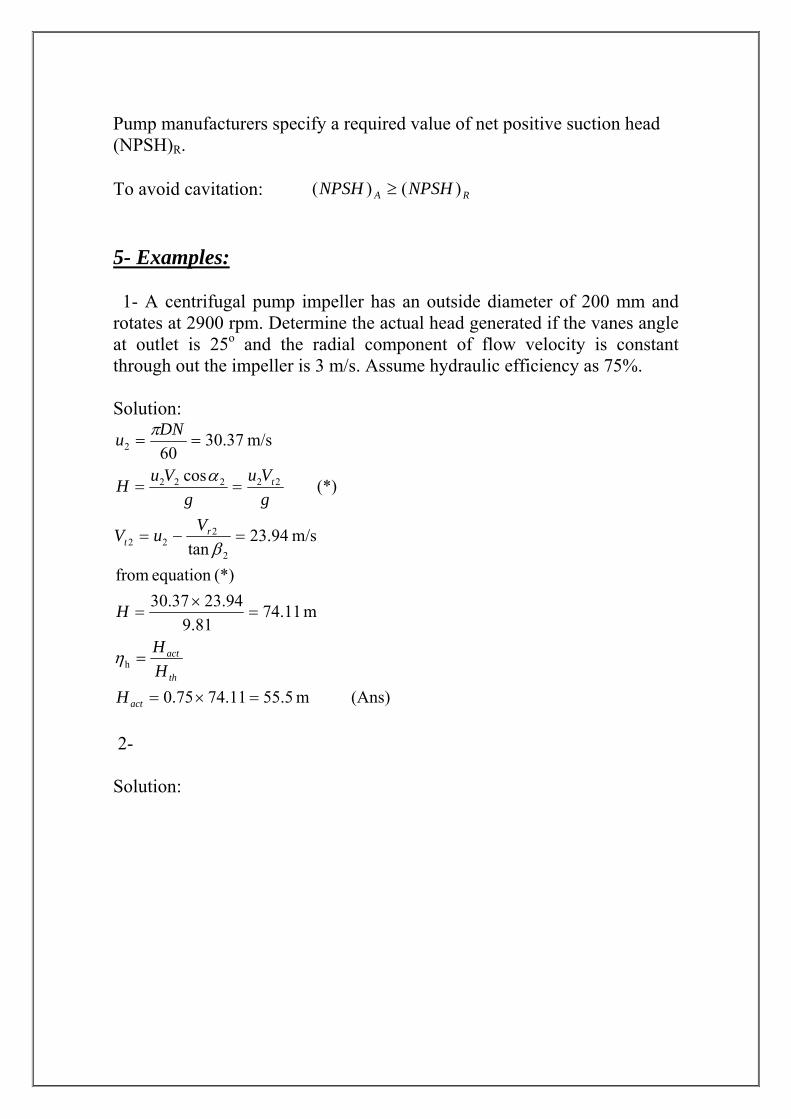
4- Cavitation in hydraulic machines: When a liquid flows into a region where its pressure is reduced to vapor pressure, it boils and vapor pockets develop in it. The vapor bubbles are carried along with the liquid until a region of higher pressure is reached, where they suddenly collapse. This process is called cavitation. Cavitation parameter (σ):
Turbine Pump
H
hZpp lossessvatm
γγγ
σ−−−
= cavitation parameter
where: patm= atmospheric pressure. pυ = absolute vapor pressure. Zs = as shown in above figures. H = net head across the machine. For cavitation not to occur at (1) the pressure must be greater than the vapor pressure of the liquid. or cσσ⟩ where cσ is the critical cavitation parameter. Net Positive Suction Head (NPSH):
γ
γγ lossessvatmA
hZppNPSH
−−−=)(
where (NPSH)A= available net positive suction head.
Pump manufacturers specify a required value of net positive suction head (NPSH)R. To avoid cavitation: RA NPSHNPSH )()( ≥ 5- Examples: 1- A centrifugal pump impeller has an outside diameter of 200 mm and rotates at 2900 rpm. Determine the actual head generated if the vanes angle at outlet is 25o and the radial component of flow velocity is constant through out the impeller is 3 m/s. Assume hydraulic efficiency as 75%. Solution:
(Ans) m 5.5511.7475.0
m 11.7481.9
94.2337.30(*) equation from
m/s 94.23tan
(*) cos
m/s 37.3060
h
2
222
22222
2
=×=
=
=×
=
=−=
==
==
act
th
act
rt
t
HHH
H
VuV
gVu
gVuH
DNu
η
β
α
π
2- Solution:
University of Technology Sheet No. 4 Mechanical Engineering Dep. Pumps Fluid Mechanics II (3 rd year) 2011/2012 1- A centrifugal water pump has an impeller with d1=0.2 m, d2=0.6 m, β1=20o, β2=10o, b1=50 mm, b2=19 mm. For 1800 rpm, neglecting losses and blade thickness, determine: a- the discharge for shock less entrance when α1=90o. b- α2 and Hth. c- the power required. d- the pressure rise through the impeller. [0.216 m3/s ; 15.11o ; 129 m ; 273.4 kW ; 1030 kN/m2] 2- A centrifugal water pump with impeller diameters d1=102 mm, d2=254 mm, and b1=76.2 mm, b2=38.1 mm, β2=60o is to pump 0.142 m3/s at 19.5 m head. Determine: β1, the speed, and the power. Neglect losses and assume no shock at the entrance (α1=90o). [43.56o ; 1146 rpm ; 27.2 kW] 3- The impeller of centrifugal pump has an outer diameter of 25 cm and an effective outlet area of 170 cm2. The blades are bent backward so that the direction of the outlet relative velocity makes an angle of 148o with the tangent drawn in the direction of impeller rotation. The diameters of the suction and delivery pipes are 15 cm and 10 cm respectively. The pump delivers 1860 l/min at 1450 rpm. The gauge points on the suction and delivery pipes close to the pump show heads of 4.6 m below and 18 m above atmosphere respectively. The head losses in the suction and delivery pipes are 2 m and 2.9 m respectively. Find the manometric efficiency assuming that water enters the pump without shock and whirl. [75%] 4- A three-stages centrifugal pump has impeller 40 cm in diameter and 2 cm wide. If the blade angle at outlet is 45o and the area occupied by the thickness of the vanes may be assumed 8% of the outlet area. If the pump delivers 3.6 m3/min when running at 920 rpm, Calculate: a- power of the pump. b- the head. c- specific speed. Assume mechanical efficiency as 88% and manometric efficiency as 77%. [65.75 kW ; 75.69 m ; Ns(U.S)=1033] 5- Tests of a 0.57 m diameter centrifugal water pump at 2134 rpm yield the following data: What is the BEP? What is the specific speed? Estimate the maximum discharge possible. [0.162 m3/s ; Ns(U.S)=1412] 6- A pump with a critical value of σ of 0.2 is to pump against a head of 20 m. The barometric pressure is 98.5 kPa abs, and the vapor pressure is 5.2 kPa abs. Friction losses from the reservoir to the pump are 0.5 m. Find the maximum allowable height of the pump relative to the water surface in the reservoir. [no more than 5 m]
Q (m3/s) 0 0.054 0.108 0.162 0.216 0.27 H (m) 102 102 102 99 90 66
Power (kW) 100.6 119.3 153 190 246 246

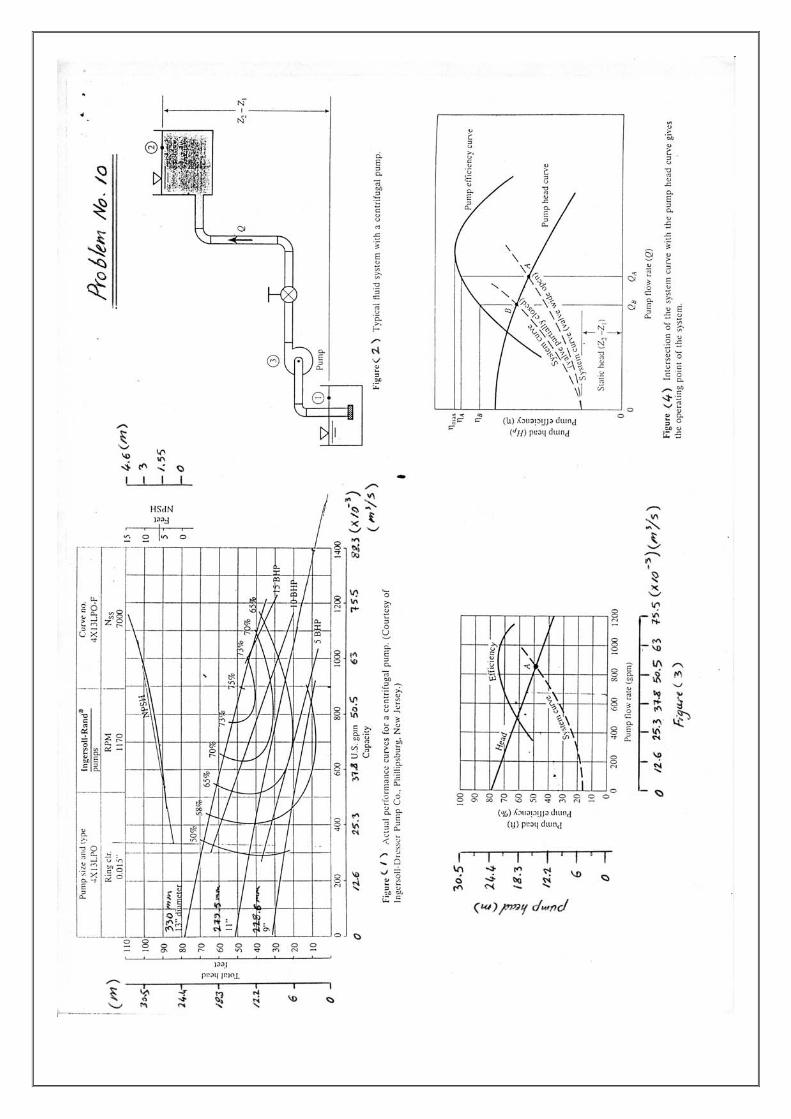
7- A centrifugal pump is installed above an open water tank. The pump is to provide a flow rate of 0.015 m3/s. Under this flow condition, the pump manufacturer specifies (NPSH)R of 5 m. Determine the maximum elevation that the pump can be installed above the water free surface without pump cavitation. The head loss hl in the 100 mm dia. suction pipeline is due to a pump inlet strainer having a loss coefficient of 15. Other head losses are negligibly small, patm= 101 kPa, pυ= 2.3 kPa. [no more than 2.28 m] 8- A centrifugal pump with a 91.5 cm impeller dia. operates at 800 rpm. If the speed is to be increased to 1200 rpm, determine the impeller diameter that should be used so that the same shaft input power would be required. [71.7 cm] 9- A 30 cm diameter centrifugal water pump is geometrically similar to a 38 cm diameter pump. The larger pump has the following test performance characteristics at the best efficiency point: speed=800 rpm, pump head=15 m, flow rate=0.126 m3/s, eff.=80%, input shaft power=23.6 kW. Determine the following for the smaller pump operating with water at 1000 rpm: a- flow rate, b- pump head, c- input power, d- maximum efficiency. [0.0775 m3/s ; 14.6 m ; 14.14 kW ; 80%] 10- The 330 mm dia. centrifugal pump whose performance curves for water are given in figure (1) has been selected to operate in the fluid system of figure (2). The following data are given for this system: Pipe dia.= 152.5 mm Total pipe length= 91.5 m Suction pipe length= 7.6 m Pipe friction factor= 0.03 Loss coefficients (Kstrainer+K1 elbow)= 3 and (Kvalve+K2 elbow)= 1.5 Elevation difference (Z2-Z1)= 4.6 m Elevation difference (Z3-Z1)= 1.55 m Determine:_ a- the pump flow rate. b- the pump efficiency. c- whether or not the selected pump is suitable for this application. (take: patm= 101 kPa, pυ= 2.3 kPa) d- the input power required to drive the pump. [54.25×10⁻³m3/s ; 74% ; suitable ; 10.5 kW]
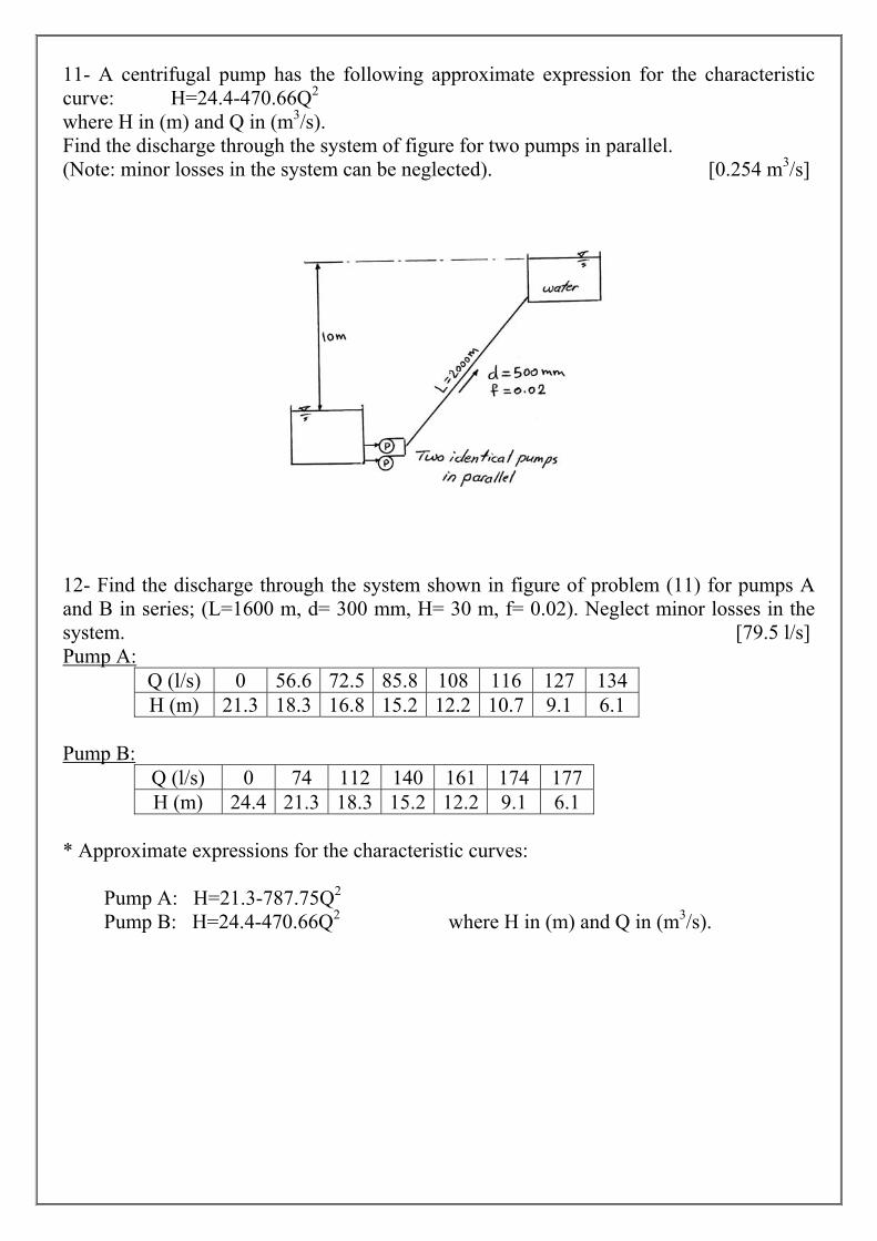
11- A centrifugal pump has the following approximate expression for the characteristic curve: H=24.4-470.66Q2 where H in (m) and Q in (m3/s). Find the discharge through the system of figure for two pumps in parallel. (Note: minor losses in the system can be neglected). [0.254 m3/s]
12- Find the discharge through the system shown in figure of problem (11) for pumps A and B in series; (L=1600 m, d= 300 mm, H= 30 m, f= 0.02). Neglect minor losses in the system. [79.5 l/s] Pump A:
Q (l/s) 0 56.6 72.5 85.8 108 116 127 134 H (m) 21.3 18.3 16.8 15.2 12.2 10.7 9.1 6.1
Pump B:
Q (l/s) 0 74 112 140 161 174 177 H (m) 24.4 21.3 18.3 15.2 12.2 9.1 6.1
* Approximate expressions for the characteristic curves: Pump A: H=21.3-787.75Q2 Pump B: H=24.4-470.66Q2 where H in (m) and Q in (m3/s).