chapter local area networking
TRANSCRIPT

CHAPTER
All-in-1 / A+ Certification Exm Gde, 6th Ed. / Meyers / 6311-3
21Local Area Networking
In this chapter, you will learn how to• Explain network technologies• Explain network operating systems• Install and configure wired networks• Install and configure wireless networks• Troubleshoot networks
Networks dominate the modern computing environment. A vast percentage of busi-nesses have PCs connected in a small local area network (LAN), and big businesses simply can’t survive with connecting their many offices into a single wide area network (WAN). Even the operating systems of today demand networks. Windows XP and Win-dows Vista, for example, come out of the box assuming you’ll attach them to a network of some sort just to make them work past 30 days (Product Activation), and they get all indignant if you don’t.
Because networks are so common today, every good tech needs to know the basics of networking technology, operating systems, implementation, and troubleshooting. Accordingly, this chapter teaches you how to build and troubleshoot a basic network.
Historical-Conceptual
Networking TechnologiesWhen the first network designers sat down at a café to figure out a way to enable two or more PCs to share data and peripherals, they had to write a lot of details on little white napkins to answer even the most basic questions. The first big question was: How? It’s easy to say, “Well, just run a wire between them!” Although most networks do manifest themselves via some type of cable, this barely touches the thousands of questions that come into play here. Here are a few of the big questions:
• How will each computer be identified? If two or more computers want to talk at the same time, how do you ensure all conversations are understood?
905
ch21.indd 905ch21.indd 905 11/27/2006 10:24:34 AM11/27/2006 10:24:34 AM

All-in-1 / A+ Certification Exm Gde, 6th Ed. / Meyers / 6311-3
CompTIA A+ Certification All-in-One Exam Guide
906• What kind of wire? What gauge? How many wires in the cable? Which wires
do which things? How long can the cable be? What type of connectors?
• If more than one PC accesses the same file, how can they be prevented from destroying each other’s changes to that file?
• How can access to data and peripherals be controlled?
Clearly, making a modern PC network entails a lot more than just stringing up some cable! Most commonly, you have a client machine, a PC that requests information or services. It needs a network interface card (NIC) that defines or labels the client on the network. A NIC also helps break files into smaller data units, called packets, to send across the network, and it helps reassemble the packets it receives into whole files. Sec-ond, you need some medium for delivering the packets between two or more PCs—most often this is a wire that can carry electrical pulses; sometimes it’s radio waves or other wireless methods. Third, your PC’s operating system has to be able to communi-cate with its own networking hardware and with other machines on the network. Fi-nally, modern PC networks often employ a server machine that provides information or services. Figure 21-1 shows a typical network layout.
Figure 21-1 A typical network
This section of the chapter looks at the inventive ways network engineers found to handle the first two of the four issues. After a brief look at core technology, the chapter dives into four specific types of networks. You’ll dig into the software side of things later in the chapter.
ch21.indd 906ch21.indd 906 11/27/2006 10:24:46 AM11/27/2006 10:24:46 AM

All-in-1 / A+ Certification Exm Gde, 6th Ed. / Meyers / 6311-3
Chapter 21: Local Area Networking
907
TopologyIf a bunch of computers connect together to make a network, some logic or order must influence the way that they connect. Perhaps each computer connects to a single main line that snakes around the office. Each computer might have its own cable, with all the cables coming together to a central point. Or maybe all the cables from all the comput-ers connect to a main loop that moves data along a track, picking up and dropping off data like a circular subway line.
A network’s topology describes the way that computers connect to each other in that network. The most common network topologies are called bus, ring, star, and mesh. Figure 21-2 shows the four types: a bus topology, where all computers connect to the network via a main line called a bus cable; a ring topology, where all computers on the network attach to a central ring of cable; a star topology, where the computers on the network connect to a central wiring point (usually called a hub); and a mesh topology, where each computer has a dedicated line to every other computer. Make sure you know these four topologies!
Figure 21-2 Clockwise from top left: bus, ring, mesh, and star topologies
If you’re looking at Figure 21-2 and thinking that a mesh topology looks amazingly resilient and robust, it is—at least on paper. Because every computer physically con-nects to every other computer on the network, even if half the PCs crash, the network
ch21.indd 907ch21.indd 907 11/27/2006 10:24:47 AM11/27/2006 10:24:47 AM

All-in-1 / A+ Certification Exm Gde, 6th Ed. / Meyers / 6311-3
CompTIA A+ Certification All-in-One Exam Guide
908still functions as well as ever (for the survivors). In a practical sense, however, imple-menting a true mesh topology network would be an expensive mess. For example, even for a tiny network with only 10 PCs, you would need 45 separate and distinct pieces of cable to connect every PC to every other PC. What a mesh mess! Because of this, mesh topologies have never been practical in a cabled network.
While a topology describes the method by which systems in a network connect, the topology alone doesn’t describe all of the features necessary to make a cabling system work. The term bus topology, for example, describes a network that consists of some number of machines connected to the network via the same piece of cable. Notice that this definition leaves a lot of questions unanswered. What is the cable made of? How long can it be? How do the machines decide which machine should send data at a spe-cific moment? A network based on a bus topology can answer these questions in a number of different ways.
Most techs make a clear distinction between the logical topology of a network—how the network is laid out on paper, with nice straight lines and boxes—and the physical topology. The physical topology describes the typically messy computer network, with cables running diagonally through the ceiling space or snaking their way through walls. If someone describes the topology of a particular network, make sure you understand whether they’re talking about the logical or physical topology.
Over the years, manufacturers and standards bodies created several specific network technologies based on different topologies. A network technology is a practical applica-tion of a topology and other critical technologies to provide a method to get data from one computer to another on a network. These network technologies have names like Ethernet and Token Ring, which will be discussed later in this chapter.
Essentials
Packets/Frames and NICsData is moved from one PC to another in discrete chunks called packets or frames. The terms packet and frame are interchangeable. Every NIC in the world has a built-in identi-fier, a binary address unique to that single network card, called a media access control (MAC) address. You read that right—every network card in the world has its own unique MAC address! The MAC address is 48 bits long, providing more than 281 trillion MAC addresses, so there are plenty of MAC addresses to go around. MAC addresses may be binary, but we represent them using 12 hexadecimal characters. These MAC addresses are burned into every NIC, and some NIC makers print the MAC address on the card. Figure 21-3 shows the System Information utility description of a NIC, with the MAC address highlighted.
NOTE NOTE Even though MAC addresses are embedded into the NIC, some NICs will allow you to change the MAC address on the NIC. This is rarely done.
ch21.indd 908ch21.indd 908 11/27/2006 10:24:47 AM11/27/2006 10:24:47 AM

All-in-1 / A+ Certification Exm Gde, 6th Ed. / Meyers / 6311-3
Chapter 21: Local Area Networking
909
Hey! I thought we were talking about packets? Well, we are, but you need to under-stand MAC addresses to understand packets. All the many varieties of packets share certain common features (Figure 21-4). First, packets contain the MAC address of the network card to which the data is being sent. Second, they have the MAC address of the network card that sent the data. Third is the data itself (at this point, we have no idea what the data is—certain software handles that question), which can vary in size de-pending on the type of frame. Finally, some type of data check (we call it a cyclic redun-dancy check or CRC) is performed and information is stored in the packet to enable the receiving network card to verify if the data was received in good order.
Figure 21-3 MAC address
1001
1011100101101011001010111101
11110001
10010111
Recipient
MAC
100101111111000110111001011010110010101111011001
Sender
MAC
Packet
Data
CRC
Figure 21-4 Generic packet/frame
ch21.indd 909ch21.indd 909 11/27/2006 10:24:47 AM11/27/2006 10:24:47 AM

All-in-1 / A+ Certification Exm Gde, 6th Ed. / Meyers / 6311-3
CompTIA A+ Certification All-in-One Exam Guide
910This discussion of packets raises the question, how big is the packet? Or more spe-
cifically, how much data do you put into each packet? How do you ensure that the re-ceiving PC understands the way that the data was broken down by the sending machine and can thus put the pieces back together? The problem in answering these questions is that they encompass so many items. When the first networks were created, everything from the frames to the connectors to the type of cable had to be invented from scratch.
To make a successful network, you need the sending and receiving PCs to use the same hardware protocol. A hardware protocol defines many aspects of a network, from the topology, to the packet type, to the cabling and connectors used. A hardware proto-col defines everything necessary to get data from one computer to another. Over the years, many hardware protocols have been implemented, with names like Token Ring, FDDI, and ARCnet, but one hardware protocol dominates the modern PC computing landscape: Ethernet. Token Ring contended with Ethernet for many years but has some-what faded from the mainstream.
A consortium of companies centered on Digital Equipment, Intel, and Xerox in-vented the first network in the mid-1970s. More than just creating a network, they wrote a series of standards that defined everything necessary to get data from one computer to another. This series of standards was called Ethernet, and it is the dominant standard for today’s networks. Ethernet comes in three main flavors defined by cabling type: coaxial, unshielded twisted pair, and fiber optic. Because all flavors of Ethernet use the same packet type, you can have any combination of hardware devices and cabling systems on an Ethernet network and all the PCs will be able to communicate just fine.
In the early 1980s, IBM developed the Token Ring network standard, again defining all aspects of the network but using radically different ideas than Ethernet. Token Ring networks continue to exist in some government departments and large corporations, but Ethernet has a far larger market share. Because Token Ring networks use a different structure for their data packets, special equipment must be used when connecting To-ken Ring and Ethernet networks. You’ll read about Token Ring later in this chapter; fo-cus on Ethernet for the moment.
Coaxial EthernetThe earliest Ethernet networks connected using coaxial cable. By definition, coaxial cable (coax for short) is a cable within a cable—two cables that share the same center or axis. Coax consists of a center cable (core) surrounded by insulation. This in turn is covered with a shield of braided cable. The inner core actually carries the signal. The shield ef-fectively eliminates outside interference. The entire cable is then surrounded by a pro-tective insulating cover.
EXAM TIP EXAM TIP You’ve seen coaxial cable before, most likely, although perhaps not in a networking situation. Your cable TV and antenna cables are coaxial, usually RG-59 or the highly shielded RG-6. Watch out for questions on the exams dealing specifically with networking hardware protocols, trying to trip you up with television-grade coaxial answers!
ch21.indd 910ch21.indd 910 11/27/2006 10:24:48 AM11/27/2006 10:24:48 AM

All-in-1 / A+ Certification Exm Gde, 6th Ed. / Meyers / 6311-3
Chapter 21: Local Area Networking
911
Thick Ethernet—10Base5The original Xerox Ethernet specification that eventually became known as 10Base5 defined a very specific type of coaxial cabling for the first Ethernet networks, called Thick Ethernet. (In fact, the name for the cable became synonymous with the 10Base5 specification.) Thick Ethernet, also known as Thicknet, was a very thick (about half an inch in diameter) type of coaxial called RG-8. RG stands for Radio Grade, an industry standard for measuring coaxial cables. The 10 in 10Base5 refers to the fact that data could move through an RG-8 cable at up to 10 Mbps with this Ethernet standard.
Every PC in a 10Base5 network connected to a single cable, called a segment or bus. Thicknet supported attaching up to 100 devices to one segment. The maximum length of a Thicknet segment was 500 meters—that’s what the 5 in 10Base5 meant (Figure 21-5). Networks like 10Base5 are laid out in a bus topology.
07 07 0707 07
10Base5Max. 100 PCs on one segment
Max. segment length is 500 meters{Figure 21-5
10Base5
Bus Topology The Ethernet bus topology works like a big telephone party line—before any device can send a packet, devices on the bus must first determine that no other device is sending a packet on the cable (Figure 21-6). When a device sends its packet out over the bus, every other network card on the bus sees and reads the packet. Ethernet’s scheme of having devices communicate like they were in a chat room is called carrier sense multiple access/collision detection (CSMA/CD). Sometimes two cards talk (send packets) at the same time. This creates a collision, and the cards themselves arbitrate to decide which one will resend its packet first (Figure 21-7).
07 07 07 07 07
CSMA/CD
Waiting... Receiving Waiting... Waiting...Sending
Figure 21-6 Devices can’t send packets while others are talking.
ch21.indd 911ch21.indd 911 11/27/2006 10:24:48 AM11/27/2006 10:24:48 AM

All-in-1 / A+ Certification Exm Gde, 6th Ed. / Meyers / 6311-3
CompTIA A+ Certification All-in-One Exam Guide
912
All PCs on a bus network share a common wire, which also means they share the data transfer capacity of that wire—or, in tech terms, they share its bandwidth. This cre-ates an interesting effect. Ten PCs chatting on a bus each get to use a much higher pro-portion of its total bandwidth than, for instance, 100 PCs on the same bus (in this case, one-tenth compared to one-hundredth). The more PCs on a bus, the more likely you’ll have a communication traffic jam. This problem does not get solved until you get be-yond coaxial Ethernet.
Reflection and Termination The ends of the bus present a bit of a problem for the signal moving along the wire. Any time a device sends voltage along a wire, some voltage bounces back, or reflects, when it reaches the end of the wire (Figure 21-8). Net-work cables are no exception. Because of CSMA/CD, these packets reflecting back and forth on the cable would bring the network down. The NICs that want to send data would wait for no reason because they would misinterpret the reflections as a “busy signal.” After a short while, the bus will get so full of reflecting packets that no other card can send data.
07 07 07 07 07
A CollisionFigure 21-7 Collisions result when two devices send simultaneously.
Figure 21-8 Reflection
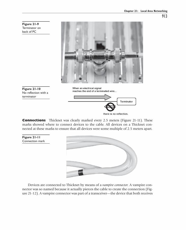
To prevent packets from being reflected, a device called a terminator must be plugged into the end of the bus cable (Figure 21-9). A terminator is nothing more than a resistor that absorbs the signal, preventing reflection (Figure 21-10). The bus topology’s need for termination is a weak spot. If the cable breaks anywhere, the reflections quickly build up and no device can send data, even if the break is not between the devices at-tempting to exchange data.
ch21.indd 912ch21.indd 912 11/27/2006 10:24:49 AM11/27/2006 10:24:49 AM
All-in-1 / A+ Certification Exm Gde, 6th Ed. / Meyers / 6311-3
Chapter 21: Local Area Networking
913
Connections Thicknet was clearly marked every 2.5 meters (Figure 21-11). These marks showed where to connect devices to the cable. All devices on a Thicknet con-nected at these marks to ensure that all devices were some multiple of 2.5 meters apart.
Figure 21-9 Terminator on back of PC
Figure 21-10 No reflection with a terminator
Figure 21-11 Connection mark
Devices are connected to Thicknet by means of a vampire connector. A vampire con-nector was so named because it actually pierces the cable to create the connection (Fig-ure 21-12). A vampire connector was part of a transceiver—the device that both receives
ch21.indd 913ch21.indd 913 11/27/2006 10:24:50 AM11/27/2006 10:24:50 AM

All-in-1 / A+ Certification Exm Gde, 6th Ed. / Meyers / 6311-3
CompTIA A+ Certification All-in-One Exam Guide
914and sends data. Transceivers enable connections between the networked devices and the common cable and detect when collisions take place. Actually, all networks use transceivers, but Thicknet used an external transceiver—often referred to as an access unit interface (AUI). The cable from the vampire connector/transceiver to the device had to be no more than 50 meters in length.
Figure 21-12 10Base5 transceiver (vampire connector)
Thick Ethernet used a bus topology so it needed terminators. A very specific 50-ohm terminator was made just for Thicknet. It had to be placed on each end of the segment. Thicknet connected to a PC’s network card via a 15-pin DB type connector. This connector was called the AUI or sometimes the Digital, Intel, Xerox (DIX) connec-tor. Figure 21-13 shows the corresponding AUI port.
Figure 21-13 DIX or AUI port
Thick Ethernet is on the way out or completely dead. Bus topology is always risky, because one break in the cable will cause the entire network to fail. In addition, Thick-net was expensive and hard to work with. The cable, transceivers, and terminators cost far more than those in any other network.
EXAM TIP EXAM TIP The vast majority of 10Base5 networks have gone away, so it’s unlikely you’ll ever encounter one in the field. The CompTIA A+ certification exams like using older or obscure technology for incorrect answers, though, so watch out for references to 10Base5, AUI, DIX, and Thicknet as wrong answers on exam questions.
ch21.indd 914ch21.indd 914 11/27/2006 10:24:50 AM11/27/2006 10:24:50 AM

All-in-1 / A+ Certification Exm Gde, 6th Ed. / Meyers / 6311-3
Chapter 21: Local Area Networking
915
Thin Ethernet—10Base2Thin Ethernet, also known as Thinnet or Cheapernet, was invented as a cheap alternative to Thicknet. Thinnet used a specific type of coax called RG-58 (Figure 21-14). This type of coax looked like a skinny version of the RG-59 or RG-6 coax used by your cable tele-vision, but it was quite different. The RG rating was clearly marked on the cable. If it was not, the cable would say something like “Thinnet” or “802.3” to let you know you had the right cable (Figure 21-15).
Figure 21-14 RG-58 coaxial
Figure 21-15 Cable markings
Although Thin Ethernet also ran at 10 Mbps, it had several big limitations compared to Thick Ethernet. Thin Ethernet supported only 30 devices per segment, and each seg-ment could be no more than 185 meters long (Figure 21-16). The 2 in 10Base2 originally meant 200 meters, but practical experience forced the standard down to 185 meters.
07 07 0707 07
10Base2Max. 30 PCs on one segment
Max. segment length is 185 meters
{Figure 21-16 10Base2
ch21.indd 915ch21.indd 915 11/27/2006 10:24:51 AM11/27/2006 10:24:51 AM

All-in-1 / A+ Certification Exm Gde, 6th Ed. / Meyers / 6311-3
CompTIA A+ Certification All-in-One Exam Guide
916On the plus side, cabling with Thinnet was a snap compared to Thicknet. The cable
was much thinner and more flexible than Thicknet. In addition, the transceiver was built into the Thinnet network card, so Thinnet did not require an external transceiver. Each Thinnet network card was simply connected to the bus cable with a T connector (Figure 21-17).
Figure 21-17 T connector
The Thinnet cable had twist-on connectors, called BNC connectors, that attached to the T connector to form the network. Termination was handled by twisting small, spe-cialized terminators onto the unused ends of the T connector on the machines at the ends of the chain. When installing Thinnet, it was important that one of the termina-tors be grounded. Special terminators could be grounded to the case of the PC. The PC also had to be grounded. You had to use a T connector! To add another PC to a Thinnet network, you simply removed the terminator from the last PC, added another piece of cable with another T connector, and added the terminator on the new end. It was also very easy to add a PC between two systems by unhooking one side of a T connector and inserting another PC and cable.
Thinnet, like its hefty cousin 10Base5, is on its way out or already dead. Very popu-lar for a time in small office/home office (SOHO) networks, the fact that it used a bus topology where any wire break meant the whole network went down made 10Base2 unacceptable in a modern network.
UTP Ethernet (10/100/100BaseT)Most modern Ethernet networks employ one of three technologies (and sometimes all three), 10BaseT, 100BaseT, or 1000BaseT. As the numbers in the names would suggest, 10BaseT networks run at 10 Mbps, 100BaseT networks run at 100 Mbps, and 1000BaseT networks—called Gigabit Ethernet—run at 1000 Mbps, or 1 Gbps. All three technolo-gies—sometimes referred to collectively as 10/100/1000BaseT—use a star bus topology and connect via a type of cable called unshielded twisted pair (UTP).
ch21.indd 916ch21.indd 916 11/27/2006 10:24:52 AM11/27/2006 10:24:52 AM

All-in-1 / A+ Certification Exm Gde, 6th Ed. / Meyers / 6311-3
Chapter 21: Local Area Networking
917
Star BusImagine taking a bus network and shrinking the bus down so it will fit inside a box. Then, instead of attaching each PC directly to the wire, you attach them via cables to special ports on the box (Figure 21-18). The box with the bus takes care of termination and all those other tedious details required by a bus network. The bus topology would look a lot like a star topology, wouldn’t it?
07
Star Bus
The bus is in the hub
Figure 21-18 Star bus
The central box with the bus is called a hub or switch. The hub provides a common point for connection for network devices. Hubs can have a wide variety of ports. Most consumer-level hubs have 4 or 8, but business-level hubs can have 32 or more ports. A hub is the old style device, still in use in many networks. A switch is a newer, far supe-rior version of a hub. Figure 21-19 shows a typical consumer-level switch.
Figure 21-19 A switch
ch21.indd 917ch21.indd 917 11/27/2006 10:24:53 AM11/27/2006 10:24:53 AM

All-in-1 / A+ Certification Exm Gde, 6th Ed. / Meyers / 6311-3
CompTIA A+ Certification All-in-One Exam Guide
918A hub provides no cure for the bandwidth-sharing problem of Ethernet networks.
If you put 32 PCs on a 32-port 100BaseT hub, you have 32 PCs sharing the 100 Mbps bandwidth. A switch addresses that problem by making each port a separate Ethernet network. Each PC gets to use the full bandwidth available, because a switch stops most collisions. Bottom line? Swap out your old hubs for newer switches and you’ll dra-matically improve your network performance.
Cheap and centralized, a star bus network does not go down if a cable breaks. True, the network would go down if the hub itself failed, but that is very rare. Even if a hub fails, replacing a hub in a closet is much easier than tracing a bus running through walls and ceilings trying to find a break!
Unshielded Twisted PairUTP cabling is the specified cabling for 10/100/1000BaseT and is the predominant ca-bling system used today. Many different types of twisted pair cabling are available, and the type used depends on the needs of the network. Twisted pair cabling consists of AWG 22—26 gauge wire twisted together into color-coded pairs. Each wire is individu-ally insulated and encased as a group in an common jacket.
CAT Levels UTP cables come in categories that define the maximum speed at which data can be transferred (also called bandwidth). The major categories (CATs) are as follows:
CAT 1 Standard phone line CAT 2 Data speeds up to 4 Mbps (ISDN and T1 lines)
CAT 3 Data speeds up to 16 Mbps CAT 4 Data speeds up to 20 Mbps
CAT 5 Data speeds up to 100 Mbps CAT 5e Data speeds up to 1 Gbps
CAT 6 Data speeds up to 10 Gbps
The CAT level should be clearly marked on the cable, as Figure 21-20 shows.
Figure 21-20 Cable markings for CAT level
The Telecommunication Industry Association/Electronics Industries Alliance (TIA/EIA) establishes the UTP categories, which fall under the TIA/EIA 568 specification. Cur-rently, most installers use CAT 5e or CAT 6 cable. Although many networks run at 10 Mbps, the industry standard has shifted to networks designed to run at 100 Mbps and faster. Because only CAT 5 or better handles these speeds, just about everyone is install-ing the higher rated cabling, even if they are running at speeds that CAT 3 or CAT 4 would do. Consequently, it is becoming more difficult to get anything but CAT 5, CAT 5e, or CAT 6 cables.
Implementing 10/100/1000BaseTThe 10BaseT, 100BaseT, and 1000BaseT cabling standards require two pairs of wires: a pair for sending and a pair for receiving. 10BaseT runs on CAT 3, CAT 4, or CAT 5 cable.
ch21.indd 918ch21.indd 918 11/27/2006 10:24:54 AM11/27/2006 10:24:54 AM

All-in-1 / A+ Certification Exm Gde, 6th Ed. / Meyers / 6311-3
Chapter 21: Local Area Networking
919100BaseT requires at least CAT 5 to run. 1000BaseT is a special case because it needs all four pairs of wires in a CAT 5e or CAT 6 cable. These cables use a connector called an RJ-45 connector. The RJ designation was invented by Ma Bell (the phone company, for you youngsters) years ago and is still used today. Currently, only two types of RJ con-nectors are used for networking: RJ-11 and RJ-45 (Figure 21-21). RJ-11 is the connector that hooks your telephone to the telephone jack. It supports up to two pairs of wires, though most phone lines use only one pair. The other pair is used to support a second phone line. RJ-11 connectors are primarily used for dial-up networking (see Chapter 22) and are not used in any common LAN installation, although a few weird (and out of business) “network in a box”–type companies used them. RJ-45 is the standard for UTP connectors. RJ-45 has connections for up to four pairs and is visibly much wider than RJ-11. Figure 21-22 shows the position of the #1 and #8 pins on an RJ-45 jack.
Figure 21-21 RJ-11 and RJ-45
18
Figure 21-22 RJ-45 pin numbers
The TIA/EIA has two standards for connecting the RJ-45 connector to the UTP cable: the TIA/EIA 568A and the TIA/EIA 568B. Both are acceptable. You do not have to follow any standard as long as you use the same pairings on each end of the cable; however, you will make your life simpler if you choose a standard. Make sure that all of your cabling uses the same standard and you will save a great deal of work in the end. Most importantly, keep records!
Like all wires, the wires in UTP are numbered. However, a number does not appear on each wire. Instead, each wire has a standardized color. Table 24-1 shows the official TIA/EIA Standard Color Chart for UTP.
ch21.indd 919ch21.indd 919 11/27/2006 10:24:54 AM11/27/2006 10:24:54 AM
All-in-1 / A+ Certification Exm Gde, 6th Ed. / Meyers / 6311-3
CompTIA A+ Certification All-in-One Exam Guide
920
Plenum versus PVC Cabling Most workplace installations of network cable go up above the ceiling and then drop down through the walls to present a nice port in the wall. The space in the ceiling, under the floors, and in the walls through which cable runs is called the plenum space. The potential problem with this cabling running through the plenum space is that the protective sheathing for networking cables, called the jack-et, is made from plastic, and if you get any plastic hot enough, it will create smoke and noxious fumes.
Standard network cables usually use PVC (poly-vinyl chloride) for the jacket, but PVC produces noxious fumes when burned. Fumes from cables burning in the plenum space can quickly spread throughout the building, so you want to use a more fire-retardant cable in the plenum space. Plenum-grade cable is simply network cabling with a fire-retardant jacket and is required for cables that go in the plenum space. Plenum-grade cable costs about three to five times more than PVC, but you should use it whenever you install cable in a plenum space.
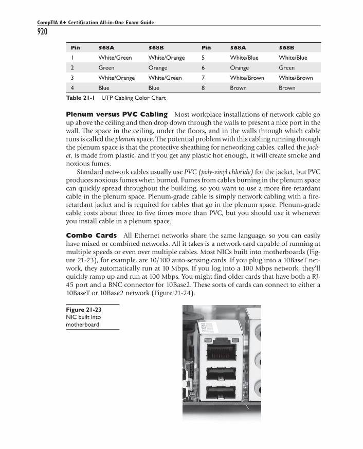
Combo Cards All Ethernet networks share the same language, so you can easily have mixed or combined networks. All it takes is a network card capable of running at multiple speeds or even over multiple cables. Most NICs built into motherboards (Fig-ure 21-23), for example, are 10/100 auto-sensing cards. If you plug into a 10BaseT net-work, they automatically run at 10 Mbps. If you log into a 100 Mbps network, they’ll quickly ramp up and run at 100 Mbps. You might find older cards that have both a RJ-45 port and a BNC connector for 10Base2. These sorts of cards can connect to either a 10BaseT or 10Base2 network (Figure 21-24).
Pin 568A 568B Pin 568A 568B
1 White/Green White/Orange 5 White/Blue White/Blue
2 Green Orange 6 Orange Green
3 White/Orange White/Green 7 White/Brown White/Brown
4 Blue Blue 8 Brown Brown
Table 21-1 UTP Cabling Color Chart
Figure 21-23 NIC built into motherboard
ch21.indd 920ch21.indd 920 11/27/2006 10:24:54 AM11/27/2006 10:24:54 AM

All-in-1 / A+ Certification Exm Gde, 6th Ed. / Meyers / 6311-3
Chapter 21: Local Area Networking
921
Hubs and Switches In a 10/100/1000BaseT network, each PC is connected to a 10/100/1000BaseT hub or switch, as mentioned earlier. To add a device to the network, simply plug another cable into the hub or switch (Figure 21-25). Remember that 10/100/1000BaseT uses the star bus topology. The hub holds the actual bus and allows access to the bus through the ports. Using a star bus topology creates a robust network; the failure of a single PC will not bring down the entire network.
Figure 21-24 Ethernet 10Base2/10BaseT combo card
Figure 21-25 Typical switch with several cables connected
In a 10/100/1000BaseT network, the maximum distance from the hub to any device is 100 meters. No more than one PC can be attached to each segment, and the maxi-mum number of PCs that can be attached to any one hub is 1024—although you will be hard pressed to find a hub with that many connectors (Figure 21-26). Most hubs come with 4, 8, 16, or 24 ports. 10/100/1000BaseT hubs act as repeaters, turning re-ceived signals into binary data and then re-creating a new signal to send out to devices connected to other ports. They need power, so make sure that the hubs are plugged into a good power source.
ch21.indd 921ch21.indd 921 11/27/2006 10:24:55 AM11/27/2006 10:24:55 AM

All-in-1 / A+ Certification Exm Gde, 6th Ed. / Meyers / 6311-3
CompTIA A+ Certification All-in-One Exam Guide
922
Crossover Cables You can actually hook two 10/100/1000BaseT network cards together without a hub by using a special UTP cable called a crossover cable. A crossover cable is a standard UTP cable but with one RJ-45 connector using the 568A standard and the other using the 568B. This reverses the signal between sending and receiving wires and thus does the job of a hub or switch. Crossover cables work great as a quick way to network two PCs. You can purchase a crossover cable at any computer store.
Duplex and Half-Duplex All modern NICs can run in full-duplex mode, mean-ing they can send and receive data at the same time. The vast majority of NICs and switches use a feature called auto-sensing to accommodate very old devices that might attach to the network and need to run in half-duplex mode. Half-duplex means that the device can send and receive but not at the same time. The walkie-talkies you played with as a kid that required you to press and hold the orange button to transmit—at which time you couldn’t hear anything—are an obvious example of a half-duplex de-vice. Half-duplex devices are exceedingly rare in modern computers, but you need to understand this option. Some NICs just can’t handle full-duplex communication when you plug them directly to another NIC using a crossover cable—that is, no switch. Dropping both NICs down from full-duplex or auto-sensing can sometimes enable these odd NICs to communicate.
Fiber Optic EthernetFiber optic cable is a very attractive way to transmit Ethernet network packets. First, because it uses light instead of electricity, fiber optic cable is immune to electrical problems such as lightning, short circuits, and static. Second, fiber optic signals travel much farther, up to 2000 meters (compared with 100 meters for 10/100/1000BaseT) with some standards. Most fiber Ethernet networks use 62.5/125 multimode fiber optic cable. All fiber Ethernet networks that use these cables require two cables. Figure 21-27 shows three of the more common connectors used in fiber optic networks. Square SC connectors are shown in the middle and on the right, and the round ST connector is on the left.
Figure 21-26 10BaseT
ch21.indd 922ch21.indd 922 11/27/2006 10:24:56 AM11/27/2006 10:24:56 AM

All-in-1 / A+ Certification Exm Gde, 6th Ed. / Meyers / 6311-3
Chapter 21: Local Area Networking
923
Like many other fiber optic connectors, the SC and ST connectors are half-duplex, meaning data flows only one way—hence the need for two cables in a fiber installation. Other half-duplex connectors you might run into are FC/PC, SMA, D4, MU, and LC. They look similar to SC and ST connectors but offer variations in size and connection. Newer and higher end fiber installations use full-duplex connectors, such as the MT-RJ connectors.
NOTE NOTE Light can be sent down a fiber optic cable as regular light or as laser light. Each type of light requires totally different fiber optic cables. Most network technologies that use fiber optics use LEDs, or light emitting diodes, to send light signals. These use multimode fiber optic cabling. Multimode fiber transmits multiple light signals at the same time, each using a different reflection angle within the core of the cable. The multiple reflection angles tend to disperse over long distances, so multimode fiber optic cables are used for relatively short distances. Network technologies that use laser light use single-mode fiber optic cabling. Using laser light and single-mode fiber optic cables allows for phenomenally high transfer rates over long distances. Except for long distance links, single-mode is currently quite rare; if you see fiber optic cabling, you can be relatively sure that it is multimode.
The two most common fiber optic standards are called 10BaseFL and 100BaseFX. As you can guess by the names, the major difference is the speed of the network (there are some important differences in the way hubs are interconnected, and so on). Fiber optic cabling is delicate, expensive, and difficult to use, so it is usually reserved for use in data centers and is rarely used to connect desktop PCs.
Figure 21-27 Typical fiber optic cables with connectors
ch21.indd 923ch21.indd 923 11/27/2006 10:24:56 AM11/27/2006 10:24:56 AM
All-in-1 / A+ Certification Exm Gde, 6th Ed. / Meyers / 6311-3
CompTIA A+ Certification All-in-One Exam Guide
924
Token RingToken Ring remains Ethernet’s most significant competitor for connecting desktop PCs to the network, but its market share has continued to shrink in recent years. Developed by IBM, Token Ring uses a combination of ring and star topologies. Because Token Ring has its own packet structure, you need special equipment to connect a Token Ring to an Ethernet network.
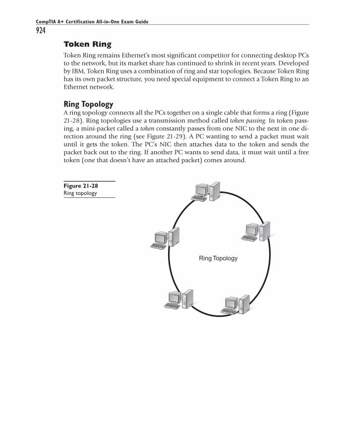
Ring TopologyA ring topology connects all the PCs together on a single cable that forms a ring (Figure 21-28). Ring topologies use a transmission method called token passing. In token pass-ing, a mini-packet called a token constantly passes from one NIC to the next in one di-rection around the ring (see Figure 21-29). A PC wanting to send a packet must wait until it gets the token. The PC’s NIC then attaches data to the token and sends the packet back out to the ring. If another PC wants to send data, it must wait until a free token (one that doesn’t have an attached packet) comes around.
07
Ring Topology
Figure 21-28 Ring topology
ch21.indd 924ch21.indd 924 11/27/2006 10:24:56 AM11/27/2006 10:24:56 AM

All-in-1 / A+ Certification Exm Gde, 6th Ed. / Meyers / 6311-3
Chapter 21: Local Area Networking
925
Implementing Token RingThe CompTIA A+ certification has a very old-school view of Token Ring networks, fo-cusing on the traditional rather than the current iterations. As such, you’ll find the ex-ams test you only on the ancient 4 Mbps or 16 Mbps networks, which depended on the type of Token Ring network cards you bought. Token Ring was originally based around the IBM Type 1 cable. Type 1 cable is a two-pair, shielded twisted pair (STP) cable de-signed to handle speeds up to 20 Mbps (Figure 21-30). Today, Token Ring topologies can use either STP or UTP cables, and UTP cabling is far more common.
Figure 21-29 Token passing
Figure 21-30 Type 1 STP Token Ring cable
ch21.indd 925ch21.indd 925 11/27/2006 10:24:57 AM11/27/2006 10:24:57 AM

All-in-1 / A+ Certification Exm Gde, 6th Ed. / Meyers / 6311-3
CompTIA A+ Certification All-in-One Exam Guide
926
NOTE NOTE Token Ring manufacturers have not rolled over and given in to the pressure of Ethernet standards, but rather have continued to adapt and innovate. Modern IEEE 802.5t Token Ring networks run at 100 Mbps or faster and, because the ring technology does not suffer from the overhead of CSMA/CD, you get phenomenally faster performance from High Speed Token Ring (HSTR) networks than on comparably speedy Ethernet. Check them out here: www.token-ring.com.
STP Types STP cables have certain categories. These are called types and are defined by IBM. The most common types are the following:
• Type 1 Standard STP with two pairs—the most common STP cable
• Type 2 Standard STP plus two pairs of voice wires
• Type 3 Standard STP with four pairs
• Type 6 Patch cable—used for connecting hubs
• Type 8 Flat STP for under carpets
• Type 9 STP with two pairs—Plenum grade
Token Ring Connectors The Type 1 Token Ring connectors are not RJ-45. In-stead, IBM designed a unique hermaphroditic connector called either an IBM-type Data Connector (IDC) or Universal Data Connector (UDC). These connectors are neither male nor female; they are designed to plug into each other (Figure 21-31). Token Ring network cards use a 9-pin female connector. A standard Token Ring cable has a her-maphroditic connector on one end and a 9-pin connector on the other.
Figure 21-31 IDC/UDC connector
Token Ring can also be used with CAT 3, 4, 5, 5e, and 6 UTP. When combined with UTP, Token Ring uses an RJ-45 connector, so from a cabling standpoint, Token Ring UTP and Ethernet UTP look the same. Many Token Ring network cards are combo cards, which means they come with both a 0-pin connection for STP and an RJ-45 con-nection for UTP.
ch21.indd 926ch21.indd 926 11/27/2006 10:24:58 AM11/27/2006 10:24:58 AM

All-in-1 / A+ Certification Exm Gde, 6th Ed. / Meyers / 6311-3
Chapter 21: Local Area Networking
927As discussed earlier, Token Ring uses a star ring topology. The central connecting
device, or concentrator, is sometimes called a hub, but the proper term is multistation access unit (MSAU or MAU). Token Ring MAUs and Ethernet hubs look similar but are not interchangeable. Each Token Ring MAU can support up to 260 PCs using STP and up to 72 PCs using UTP. Using UTP, the maximum distance from any MAU to a PC is 45 meters. Using STP, the maximum distance from any MAU to a PC is 100 meters (Fig-ure 21-32). Token Ring can also uses repeaters, but the repeaters can be used only be-tween MAUs. With a repeater, the functional distance between two MAUs increases to 360 meters (with UTP) and 720 meters (with STP).
07
Token RingMax. 260 PCs on each STP ring
or 72 PCs on a UTP ring
Max. segment length is 100 meters for STPand 45 meters for UTP
Max. 1024 PCs per MAU
{Figure 21-32 Token Ring specifications
Parallel/SerialIt would be unfair not to give at least a token nod to the possibility of making direct cable connections using the parallel or serial ports on a pair of PCs. All versions of Windows have complete support for allowing two, and no more than two, systems to network together using either parallel or serial cables. You need crossover versions of IEEE1284 cables for parallel and RS-232 cables for serial. These should be considered only as a last resort option, given the incredibly slow speeds of parallel and especially serial cable transmission compared to that of Ethernet and Token Ring. Direct cable connections should never be used unless no other viable alternative exists.
FireWireYou can connect two computers together using FireWire cables. Apple designed FireWire to be network aware, so the two machines will simply recognize each other and, assum-ing they’re configured to share files and folders, you’re up and running. See the section “Sharing and Security” later in this chapter for more details.
USBYou can also connect two computers using USB, but it’s not quite as elegant as FireWire. You can use several options. The most common way is to plug a USB NIC into each PC and then run a UTP crossover cable between the Ethernet ports. You can buy a special USB crossover cable to connect the two machines. Finally, at least one company makes a product that enables you to connect with a normal USB cable, called USB Duet.
ch21.indd 927ch21.indd 927 11/27/2006 10:24:58 AM11/27/2006 10:24:58 AM

All-in-1 / A+ Certification Exm Gde, 6th Ed. / Meyers / 6311-3
CompTIA A+ Certification All-in-One Exam Guide
928
IT Technician
Network Operating SystemsAt this point in the discussion of networking, you’ve covered two of the four main re-quirements for making a network work. Through Ethernet or Token Ring hardware protocols, you have a NIC for the PC that handles splitting data into packets and put-ting the packets back together at the destination PC. You’ve got a cabling standard to connect the NIC to a hub/switch or MSAU, thus making that data transfer possible. Now it’s time to dive into the third and fourth requirements for a network. You need an operating system that can communicate with the hardware and with other networked PCs, and you need some sort of server machine to give out data or services. The third and fourth requirements are handled by a network operating system.
EXAM TIP EXAM TIP The CompTIA A+ Essentials exam assumes you have a working knowledge of network operating systems.
In a classic sense, a network operating system (NOS) communicates with the PC hard-ware—of whichever hardware protocol—and makes the connections among multiple machines on a network. The NOS enables one or more PCs to act as a server machine and share data and services over a network—to share resources, in other words. You then need to run software on client computers to enable those computers to access the shared resources on the server machine.
Every Windows OS is an NOS and enables the PC to share resources and access shared resources. But it doesn’t come out of the box ready to work on all networks! You need to configure Windows to handle all three tasks to make all this work: install a network protocol to communicate with hardware, enable server software to share re-sources, and install client software to enable the PC to access shared resources.
All NOSs are not alike, even among Windows. Before you can share resources across a network, you must answer a number of questions. How do you make that happen? Can everyone share his or her hard drives with everyone else? Should you place limits on sharing? If everyone needs access to a particular file, where will it be stored? What about security? Can anyone access the file? What if someone erases it accidentally? How are backups to be handled? Different NOSs answer these questions differently. Let’s look at network organization and then turn to protocols, client software, and server software.
Network OrganizationAll NOSs can be broken into three basic organizational groups: client/server, peer-to-peer, and domain-based. All Windows PCs can function as network clients and servers, so this muddies the waters a bit. Let’s take a look at traditional network organization.
Client/ServerThe client/server solution to all the sharing resources questions is to take one machine and dedicate it as a resource to be shared over the network. This machine will have a
ch21.indd 928ch21.indd 928 11/27/2006 10:24:59 AM11/27/2006 10:24:59 AM

All-in-1 / A+ Certification Exm Gde, 6th Ed. / Meyers / 6311-3
Chapter 21: Local Area Networking
929dedicated NOS optimized for sharing files. This special OS includes powerful caching software that enables high-speed file access. It will have extremely high levels of protec-tion and an organization that permits extensive control of the data. This machine is called a dedicated server. All of the other machines that use the data are called clients (because it’s what they usually are) or workstations.
The client/server system dedicates one machine to act as a “server.” Its only function is to serve up resources to the other machines on the network. These servers do not run Win-dows 9x or Windows XP. They use highly sophisticated and expensive NOSs that are opti-mized for the sharing and administration of network resources. Dedicated server operating systems include Windows 2003 Server, Novell NetWare, and some versions of Linux.
Novell NetWare servers provide the most pure example of a dedicated server. A Net-Ware server doesn’t provide a user environment for running any applications except for tools and utilities. It just serves shared resources; it does not run programs such as Excel or CorelDraw. Many network administrators will even remove the keyboard and moni-tor from a NetWare server to keep people from trying to use it. NetWare has its own commands and requires substantial training to use, but in return, you get an amazingly powerful NOS! While Linux and Windows 2003 server machines can technically run client applications such as word processors, they have been optimized to function as servers and you don’t typically use them to run end-user applications.
NOTE NOTE The terms client and server are, to say the least, freely used in the Windows world. Keep in mind that a client generally refers to any process (or in this context, computer system) that can request a resource or service, and a server is any process (or system) that can fulfill the request.
Novell NetWare provides excellent security for shared resources. Its security permis-sions are similar to Microsoft NTFS permissions.
Peer-to-PeerSome networks do not require dedicated servers—every computer can perform both server and client functions. A peer-to-peer network enables any or all of the machines on the network to act as a server. Peer-to-peer networks are much cheaper than client/server networks, because the software costs less and does not require that you purchase a high-end machine to act as the dedicated server. The most popular peer-to-peer NOSs today are Windows 2000/XP and Macintosh OS X.
The biggest limiting factor to peer-to-peer networking is that it’s simply not de-signed for a large number of computers. Windows has a built-in limit (10) to the num-ber of users who can concurrently access a shared file or folder. Microsoft recommends that peer-to-peer workgroups not exceed 15 PCs. Beyond that, creating a domain-based network makes more sense.
Security is the other big weakness of peer-to-peer networks. Each system on a peer-to-peer network maintains its own security.
Windows 2000 Professional and Windows XP Professional enable you to tighten security by setting NTFS permissions locally, but you are still required to place a local account on every system for any user who’s going to access resources. So, even though you get better security in a Windows 2000 Professional or Windows XP Professional
ch21.indd 929ch21.indd 929 11/27/2006 10:24:59 AM11/27/2006 10:24:59 AM

All-in-1 / A+ Certification Exm Gde, 6th Ed. / Meyers / 6311-3
CompTIA A+ Certification All-in-One Exam Guide
930peer-to-peer network, system administration entails a lot of running around to indi-vidual systems to create and delete local users every time someone joins or leaves the network. In a word: bleh.
Peer-to-peer workgroups are little more than a pretty way to organize systems to make navigating through My Network Places a little easier (Figure 21-33). In reality, workgroups have no security value. Still, if your networking needs are limited—such as a small home network—peer-to-peer networking is an easy and cheap solution.
Figure 21-33 Multiple workgroups in a network
Domain-BasedOne of the similarities between the client/server network model and peer-to-peer net-works is that each PC in the network maintains its own list of user accounts. If you want to access a server, you must log on. When only one server exists, the logon process takes only a second and works very well. The trouble comes when your network contains multiple servers. In that case, every time you access a different server, you must repeat the logon process (Figure 21-34). In larger networks containing many servers, this be-comes a time-consuming nightmare not only for the user, but also for the network ad-ministrator.
ch21.indd 930ch21.indd 930 11/27/2006 10:24:59 AM11/27/2006 10:24:59 AM

All-in-1 / A+ Certification Exm Gde, 6th Ed. / Meyers / 6311-3
Chapter 21: Local Area Networking
931
A domain-based network provides an excellent solution for the problem of multi-ple logins. In a domain-based environment, one or more dedicated servers called do-main controllers hold the security database for all systems. This database holds a list of all users and passwords in the domain. When you log on to your computer or to any computer, the logon request goes to an available domain controller, to verify the ac-count and password (Figure 21-35).
You have
to log on
to me!
You have
to log on
to me!
You have
to log on
to me!
You have
to log on
to me!
Who
should I
log on to?
Figure 21-34 Multiple logins
Figure 21-35 A domain controller eliminates the need for multiple logins.
Modern domain-based networks use what is called a directory service to store user and computer account information. Current versions of Novell NetWare move from the strict client/server model described to a directory service-based model implement-ing the appropriately named NetWare Directory Service (NDS). Large Microsoft-based networks use the Active Directory (AD) directory service. Think of a directory service as a big, centralized index, similar to a telephone book, that each PC accesses to locate resources in the domain.
Server versions of Microsoft Windows look and act similar to the workstation ver-sions, but they come with extra networking capabilities, services, and tools to enable
ch21.indd 931ch21.indd 931 11/27/2006 10:25:00 AM11/27/2006 10:25:00 AM

All-in-1 / A+ Certification Exm Gde, 6th Ed. / Meyers / 6311-3
CompTIA A+ Certification All-in-One Exam Guide
932them to take on the role of domain controller, file server, remote access services (RAS) server, application server, Web server, and so on. A quick glance at the options you have in Administrative Tools shows how much more full-featured the server versions are com-pared to the workstation versions of Windows. Figure 21-36 shows the Administrative Tools options on a typical Windows XP workstation. These should be familiar to you. Figure 21-37 shows the many extra tools you need to work with Windows 2000 Server.
Figure 21-36 Administrative Tools in Windows XP Professional
Figure 21-37 Administrative Tools in Windows 2000 Server
ch21.indd 932ch21.indd 932 11/27/2006 10:25:08 AM11/27/2006 10:25:08 AM

All-in-1 / A+ Certification Exm Gde, 6th Ed. / Meyers / 6311-3
Chapter 21: Local Area Networking
933Every Windows system contains a special account called the administrator account.
This one account has complete and absolute power over the entire system. When you install Windows 2000 or XP, you must create a password for the administrator account. Anyone who knows the administrator password has the ability to install/delete any program, read/change/delete any file, run any program, and change any system setting. As you might imagine, you should protect the administrator password carefully. With-out it, you cannot create additional accounts (including additional accounts with ad-ministrative privileges) or change system settings. If you lose the administrator password (and no other account with administrative privileges exists), you have to reinstall Win-dows completely to create a new administrator account—so don’t lose it!
In Windows 2000, open the Properties window for My Computer, and select the Network Identification tab, as shown in Figure 21-38. This shows your current selec-tion. Windows XP calls the tab Computer Name and renames a few of the buttons (Figure 21-39). Clicking the Network ID button opens the Network Identification Wiz-ard, but most techs just use the Change button (Figure 21-40). Clicking the Change button does the same thing as clicking the Network ID button, but the wizard does a lot of explaining that you don’t need if you know what you want to do. Make sure you have a valid domain account or you won’t be able to log in to a domain.
Figure 21-38 Network Identification tab in Windows 2000
ch21.indd 933ch21.indd 933 11/27/2006 10:25:08 AM11/27/2006 10:25:08 AM

All-in-1 / A+ Certification Exm Gde, 6th Ed. / Meyers / 6311-3
CompTIA A+ Certification All-in-One Exam Guide
934
At this point, you’ve prepared the OS to network in general, but now you need to talk to the specific hardware. For that, you need to load protocols.
Figure 21-39 Computer Name tab in Windows XP
Figure 21-40 Using the Change button
ch21.indd 934ch21.indd 934 11/27/2006 10:25:08 AM11/27/2006 10:25:08 AM

All-in-1 / A+ Certification Exm Gde, 6th Ed. / Meyers / 6311-3
Chapter 21: Local Area Networking
935
ProtocolsSimply moving data from one machine to another is hardly sufficient to make a com-plete network; many other functions need to be handled. For example, if a file is being copied from one machine to another, something must keep track of all the packets so that the file can be properly reassembled. If many machines are talking to the same machine at once, that machine must somehow keep track of which packets it sends to or receives from each of the other PCs.
Another issue arises if one of the machines in the network has its network card re-placed. Up to this point, the only way to distinguish one machine from another was by the MAC address on the network card. To solve this, each machine must have a name, an identifier for the network, which is “above” the MAC address. Each machine, or at least one of them, needs to keep a list of all the MAC addresses on the network and the names of the machines, so that packets and names can be correlated. That way, if a PC’s network card is replaced, the network, after some special queries, can update the list to associate the name of the PC with its new network card’s MAC address.
Network protocol software takes the incoming data received by the network card, keeps it organized, sends it to the application that needs it, and then takes outgoing data from the application and hands it to the NIC to be sent out over the network. All networks use some protocol. Although many different protocols exist, three dominate the world of PCs—NetBEUI from Microsoft, IPX/SPX from Novell, and TCP/IP from UNIX/Internet.
NetBEUIDuring the 1980s, IBM developed NetBIOS Extended User Interface (NetBEUI), the de-fault protocol for Windows for Workgroups, LANtastic, and Windows 95. NetBEUI of-fers small size and a relatively high speed, but it can’t be used for routing. Its inability to handle routing limits NetBEUI to networks smaller than about 200 nodes.
NOTE NOTE A node is any device that has a network connection—usually this means a PC, but other devices can be nodes. For example, many printers now connect directly to a network and can therefore be deemed nodes. I use the term node extensively in the rest of the chapter in place of PC or networked computer. This is especially true when I talk about wireless technologies, because that’s the term the manufacturers use.
IPX/SPXNovell developed the Internetwork Packet Exchange/Sequenced Packet Exchange (IPX/SPX) protocol exclusively for its NetWare products. The IPX/SPX protocol is speedy, works well with routers, and takes up relatively little RAM when loaded. Microsoft imple-ments a version of IPX/SPX called NWLink.
ch21.indd 935ch21.indd 935 11/27/2006 10:25:09 AM11/27/2006 10:25:09 AM

All-in-1 / A+ Certification Exm Gde, 6th Ed. / Meyers / 6311-3
CompTIA A+ Certification All-in-One Exam Guide
936
NOTE NOTE Although IPX/SPX is strongly associated with Novell NetWare networks, versions of NetWare since version 5 have adopted TCP/IP as their default, native protocol.
TCP/IPTransmission Control Protocol/Internet Protocol (TCP/IP) was originally developed for the Internet’s progenitor, the Advanced Research Projects Agency Network (ARPANET) of the U.S. Department of Defense. In 1983, TCP/IP became the built-in protocol for the popular BSD UNIX, and other flavors of UNIX quickly adopted it as well. TCP/IP is the best protocol for larger (more than 200 nodes) networks. The biggest network of all, the Internet, uses TCP/IP as its protocol. Windows NT also uses TCP/IP as its default protocol. TCP/IP lacks speed and takes up a large amount of memory when loaded, but it is robust, well understood, and universally supported.
AppleTalkAppleTalk is the proprietary Apple protocol. Similar to IPX, it is small and relatively fast. The only reason to use the AppleTalk protocol is to communicate with older Apple computers on a network. Apple Macintosh OS X uses TCP/IP natively, so you won’t need AppleTalk to plug a modern Mac into a Windows network.
Client SoftwareTo access data or resources across a network, a Windows PC needs to have client soft-ware installed for every kind of server that you want to access. When you install a net-work card and drivers, Windows installs at least one set of client software, called Client for Microsoft Networks (Figure 21-41). This client enables your machine to do the obvi-ous: connect to a Microsoft network! To connect to a NetWare network, you’d need to add Client Service for NetWare. Internet-based services work the same way. You need a Web client (such as Internet Explorer) to access a Web server. We’ll go through the in-stallation and configuration steps for the Microsoft and NetWare clients a little later in this chapter. For now, you need to know that Windows PCs don’t just access shared data magically but require that client software be installed.
ch21.indd 936ch21.indd 936 11/27/2006 10:25:09 AM11/27/2006 10:25:09 AM

All-in-1 / A+ Certification Exm Gde, 6th Ed. / Meyers / 6311-3
Chapter 21: Local Area Networking
937
Server SoftwareYou can turn any Windows PC into a server, simply by enabling the sharing of files, folders, and printers. Windows 2000 and XP have File and Printer Sharing installed but not acti-vated by default, but activating it requires nothing more than a click on a check box next to the File and Printer Sharing for Microsoft Networks option, as shown in Figure 21-41.
Installing and Configuring a Wired NetworkAlmost halfway through the chapter and we’re finally getting to the good stuff—install-ing and configuring a network! To have network connectivity, you need to have three things in place:
• NIC The physical hardware that connects the computer system to the network media.
• Protocol The language that the computer systems use to communicate.
• Network client The interface that allows the computer system to speak to the protocol.
Figure 21-41 LAN Properties window showing Client for Microsoft Networks installed (along with other network software)
ch21.indd 937ch21.indd 937 11/27/2006 10:25:09 AM11/27/2006 10:25:09 AM

All-in-1 / A+ Certification Exm Gde, 6th Ed. / Meyers / 6311-3
CompTIA A+ Certification All-in-One Exam Guide
938If you want to share resources on your PC with other network users, you also need
to enable Microsoft’s File and Printer Sharing. This installs the services and software that turns a Windows PC into a server.
Plus, of course, you need to connect the PC to the network hub or switch via some sort of cable (preferably CAT 6 with Gigabit Ethernet cranking through the wires, but that’s just me!). When you install a NIC, by default, Windows 2000 and XP Profes-sional install the TCP/IP protocol, the Client for Microsoft Networks, and File and Printer Service upon setup. Other versions of Windows require you to jump through a couple more hoops and install some or all of this stuff to get connectivity.
Installing a NICThe NIC is your computer system’s link to the network, and installing one is the first step required to connect to a network. NICs are manufactured to operate on specific media and network types, such as 100BaseT Ethernet or 16 Mbps Token Ring. Follow the manufacturer’s instructions for installation. If your NIC is of recent vintage, it will be detected, installed, and configured automatically by Windows 2000 or Windows XP. You might need a driver disc or a driver download from the manufacturer’s Web site if you install the latest and greatest Gigabit Ethernet card.
Add Hardware WizardThe Add Hardware Wizard automates installation of non–plug-and-play devices, or plug-and-play devices that were not detected correctly. Start the wizard by clicking Start | Settings | Control Panel, and double-clicking the icon for the Add Hardware applet. (Note that earlier versions of Windows call this the Add/Remove Hardware applet.) Click the Next button to select the hardware task you wish to perform, and follow the prompts to complete the wizard.
NOTE NOTE If you have the option, you should save yourself potential headaches and troubleshooting woes by acquiring new, name-brand NICs for your Windows installation.
Configuring a Network ClientTo establish network connectivity, you need a network client installed and configured properly. You need a client for every type of server NOS to which you plan to connect on the network. Let’s look at the two most used for Microsoft and Novell networks.
Client for Microsoft NetworksInstalled as part of the OS installation, the Client for Microsoft Networks rarely needs configuration, and, in fact, few configuration options are available. To start it in Win-dows XP, click Start, and then right-click My Network Places and select Properties. In Windows 2000, click Start | Settings | Network and Dial-up Connections.
In all versions of Windows, your next step is to double-click the Local Area Connec-tion icon, click the Properties button, highlight Client for Microsoft Networks, and click the Properties button. Note that there’s not much to do here. Unless told to do something by a network administrator, just leave this alone.
ch21.indd 938ch21.indd 938 11/27/2006 10:25:10 AM11/27/2006 10:25:10 AM

All-in-1 / A+ Certification Exm Gde, 6th Ed. / Meyers / 6311-3
Chapter 21: Local Area Networking
939
Client Service for NetWareMicrosoft’s Client Service for NetWare provides access to file and print resources on NetWare 3.x and 4.x servers. Client Service for NetWare supports some NetWare utilities and NetWare-aware applications. To connect Microsoft client workstations to NetWare servers running NDS also requires the Microsoft Service for NetWare Directory Services (NDS). Once installed, Client Service for NetWare offers no configuration options.
NOTE NOTE Client Service for NetWare does not support the IP protocol used in NetWare 5.x and more recent versions of NetWare.
Configuring Simple ProtocolsProtocols come in many different flavors and perform different functions on the net-work. Some, such as NetBEUI, lack elements that allow their signals to travel through routers, making them non-routable (essentially, this protocol is unsuitable for a large network that uses routers to re-transmit data). The network protocols supported by Windows include NetBEUI, NWLink (IPX/SPX), and TCP/IP, although Windows XP drops support for NetBEUI. This section looks at installing and configuring the simple protocols used by Windows 2000: NetBEUI and NWLink.
NetBEUINetBEUI is easy to configure, since no network addresses are needed. Generally, all you need to establish a connection between computer systems using NetBEUI is a NetBIOS computer name. NetBIOS names must be unique and contain 15 or fewer characters, but other than that there isn’t much to it. To install the NetBEUI protocol in any version of Windows except XP, follow these steps:
1. In Windows 2000, click Start | Settings | Network and Dial-up Connections. Double-click the Local Area Connection icon to bring up the Local Area Connection Status dialog box (Figure 21-42).
Figure 21-42 LAN Status dialog box in Windows 2000
ch21.indd 939ch21.indd 939 11/27/2006 10:25:10 AM11/27/2006 10:25:10 AM

All-in-1 / A+ Certification Exm Gde, 6th Ed. / Meyers / 6311-3
CompTIA A+ Certification All-in-One Exam Guide
940 2. Click the Properties button to bring up the Local Area Connection Properties
dialog box (Figure 21-43).
Figure 21-43 LAN Properties dialog box in Windows 2000
3. Click the Install button. In the Select Network Component Type dialog box, highlight Protocol and click the Add button (Figure 21-44).
Figure 21-44 Adding a protocol
4. In the Select Network Protocol dialog box, select NetBEUI Protocol (Figure 21-45), and click the OK button. You will be prompted to reboot the system to make the changes take effect.
ch21.indd 940ch21.indd 940 11/27/2006 10:25:10 AM11/27/2006 10:25:10 AM

All-in-1 / A+ Certification Exm Gde, 6th Ed. / Meyers / 6311-3
Chapter 21: Local Area Networking
941
NWLink (IPX/SPX)As mentioned, NWLink is Microsoft’s implementation of the IPX/SPX protocol. The Microsoft version of NWLink provides the same level of functionality as the Novell protocol and also includes an element for resolving NetBIOS names. NWLink packages data to be compatible with client/server services on NetWare networks, but it does not provide access to NetWare File and Print Services. For this, you also need to install the Client Service for NetWare, as noted earlier.
Follow the same steps used to install NetBEUI to install NWLink, except choose NWLink rather than NetBEUI when you make your final selection. You’ll be prompted to reboot after adding the protocol.
NWLink is a relatively easy protocol to configure. Normally, the only settings you may need to specify are the internal network number and frame type (usually, however, the default values are sufficient). The internal network number is used by the network for routing purposes. The frame type specifies how the data is packaged for transport over the network. For computers to communicate by NWLink, they must have the same frame types. By default, the frame type is set to Auto Detect.
NOTE NOTE When NWLink is set to Auto Detect the frame type, it will detect only one type, searching in the following order: 802.2, 802.3, 802.5.
To configure NWLink properties manually, follow these steps:
1. In Windows XP, click Start | Control Panel and open the Network Connections applet. Double-click the Local Area Connection icon. In Windows 2000, click Start | Settings | Network and Dial-up Connections, and double-click the Local Area Connection icon.
Figure 21-45 Selecting NetBEUI
ch21.indd 941ch21.indd 941 11/27/2006 10:25:10 AM11/27/2006 10:25:10 AM

All-in-1 / A+ Certification Exm Gde, 6th Ed. / Meyers / 6311-3
CompTIA A+ Certification All-in-One Exam Guide
942 2. Click the Properties button, highlight NWLink IPX/SPX/NetBIOS Compatible
Transport Protocol, and click the Properties button.
3. In the NWLink IPX/SPX/NetBIOS Compatible Transport Protocol properties dialog box, set the internal network number and frame type (Figure 21-46).
Figure 21-46 Configuring NWLink
Configuring TCP/IPThis final section on protocols covers TCP/IP, the primary protocol of most modern networks, including the Internet. For a PC to access the Internet, it must have TCP/IP loaded and configured properly. TCP/IP has become so predominant that most net-work folks use it even on networks that do not connect to the Internet. Although TCP/IP is very powerful, it is also a bit of a challenge to set up. So whether you are installing a modem for a dial-up connection to the Internet or setting up 500 computers on their own private intranet, you must understand some TCP/IP basics. You’ll go through the following basic sections of the protocol and then you’ll look at specific steps to install and configure TCP/IP.
Network AddressingAny network address must provide two pieces of information: it must uniquely identify the machine and it must locate that machine within the larger network. In a TCP/IP network, the IP address identifies the PC and the network on which it resides.
IP Addresses In a TCP/IP network, the systems don’t have names but rather use IP addresses. The IP address is the unique identification number for your system on the
ch21.indd 942ch21.indd 942 11/27/2006 10:25:11 AM11/27/2006 10:25:11 AM

All-in-1 / A+ Certification Exm Gde, 6th Ed. / Meyers / 6311-3
Chapter 21: Local Area Networking
943network. Part of the address identifies the network, and part identifies the local com-puter (host) address on the network. IP addresses consist of four sets of eight binary numbers (octets), each set separated by a period. This is called dotted-decimal notation. So, instead of a computer being called SERVER1, it gets an address like so:
202.34.16.11
Written in binary form, the address would look like this:
11110010.00000101.00000000.00001010
But the TCP/IP folks decided to write the decimal equivalents:
00000000 = 000000001 = 100000010 = 2...11111111 = 255
IP addresses are divided into class licenses, which correspond with the potential size of the network: Class A, Class B, and Class C. Class A licenses were intended for huge companies and organizations, such as major multinational corporations, univer-sities, and governmental agencies. Class B licenses were assigned to medium-size com-panies, and Class C licenses were designated for smaller LANs. Class A networks use the first octet to identify the network address and the remaining three octets to identify the host. Class B networks use the first two octets to identify the network address and the remaining two octets to identify the host. Class C networks use the first three octets to identify the network address and the last octet to identify the host. Table 21-2 lists range (class) assignments.
Network Class Address Range No. of Network Addresses Available
No. of Host Nodes (Computers) Supported
A 1–126 129 16,777,214
B 128–191 16,384 65,534
C 192–223 2,097,152 254
Table 21-2 Class A, B, and C Addresses
You’ll note that the IP address ranges listed above skip from 126.x.x.x to 128.x.x.x. That’s because the 127 address range (i.e., 127.0.0.1–127.255.255.255) is reserved for network testing (loopback) operations. (We usually just use the address 127.0.0.1 for loopback purposes, and call it the localhost address, but any address that starts off with 127 will work just as well.) That’s not the only reserved range, either! Each network class has a specific IP address range reserved for private networks—traffic from these networks doesn’t get routed to the Internet at large. Class A’s private range goes from 10.0.0.1 to 10.255.255.254. Class B’s private range is 172.16.0.1 up to 172.16.255.254. Class C has two private addresses ranges: 192.168.0.0 to 192.168.255.254 for manually configured
ch21.indd 943ch21.indd 943 11/27/2006 10:25:11 AM11/27/2006 10:25:11 AM

All-in-1 / A+ Certification Exm Gde, 6th Ed. / Meyers / 6311-3
CompTIA A+ Certification All-in-One Exam Guide
944addresses, and 169.254.0.1 to 169.254.255.254 to accommodate the Automatic Private IP Addressing (APIPA) function.
NOTE NOTE Pinging the loopback is the best way to test if a NIC is working properly. To test a NIC’s loopback, the other end of the cable must be in a working switch or you must use a loopback device.
Subnet Mask The subnet mask is a value that distinguishes which part of the IP address is the network address and which part of the address is the host address. The subnet mask blocks out (or “masks”) the network portions (octets) of an IP address. Certain subnet masks are applied by default. The default subnet mask for Class A ad-dresses is 255.0.0.0; for Class B, it’s 255.255.0.0; and for Class C, 255.255.255.0. For example, in the Class B IP address 131.190.4.121 with a subnet mask of 255.255.0.0, the first two octets (131.190) make up the network address, and the last two (4.121) make up the host address.
EXAM TIP EXAM TIP The CompTIA A+ certification exams do not require you to break down IP addresses and subnet masks into their binary equivalents or to deal with non-standard subnet masks like 255.255.240.0, but you should know what IP addresses and subnet masks are and how to configure your PC to connect to a TCP/IP network.
TCP/IP ServicesTCP/IP is a very different type of protocol. Although it supports File and Printer Shar-ing, it adds a number of special sharing functions unique only to it, lumped together under the umbrella term TCP/IP services. The most famous TCP/IP service is called hy-pertext transfer protocol (HTTP), the language of the World Wide Web. If you want to surf the Web, you must have TCP/IP. But TCP/IP supplies many other services beyond just HTTP. Using a service called Telnet, for example, you can access a remote system as though you were actually in front of that machine.
Another example is a handy utility called Ping. Ping enables one machine to check whether it can communicate with another machine. Figure 21-47 shows an example of
ch21.indd 944ch21.indd 944 11/27/2006 10:25:11 AM11/27/2006 10:25:11 AM

All-in-1 / A+ Certification Exm Gde, 6th Ed. / Meyers / 6311-3
Chapter 21: Local Area Networking
945
The goal of TCP/IP is to link any two hosts (remember, a host is just a computer in TCP/IP lingo), whether the two computers are on the same LAN or on some other net-work within the WAN. The LANs within the WAN are linked together with a variety of different types of connections, ranging from basic dial-ups to dedicated, high-speed (and expensive) data lines (Figure 21-48). To move traffic between networks, you use specialized computers called routers (Figure 21-49). Each host will send traffic to the router only when that data is destined for a remote network, cutting down on traffic across the more expensive WAN links. The host makes these decisions based on the destination IP address of each packets. Routers are most commonly used in TCP/IP networks, but other protocols also use them, especially IPX/SPX.
Figure 21-47 Ping in action
Ping running on a Windows 2000 system. Isn’t it interesting that many TCP/IP services run from a command prompt? Good thing you know how to access one! I’ll show you other services in a moment.
ch21.indd 945ch21.indd 945 11/27/2006 10:25:12 AM11/27/2006 10:25:12 AM

All-in-1 / A+ Certification Exm Gde, 6th Ed. / Meyers / 6311-3
CompTIA A+ Certification All-in-One Exam Guide
946
TCP/IP SettingsTCP/IP has a number of unique settings that you must set up correctly to ensure proper network functioning. Unfortunately, these settings can be quite confusing, and there
07 07 0707 07
07 07 0707 07
07 07 0707 07
07 07 0707 07
07 07 0707 07
LANLAN
LAN
LAN
LAN
WAN
Figure 21-48 WAN concept
Figure 21-49 Typical router
ch21.indd 946ch21.indd 946 11/27/2006 10:25:12 AM11/27/2006 10:25:12 AM

All-in-1 / A+ Certification Exm Gde, 6th Ed. / Meyers / 6311-3
Chapter 21: Local Area Networking
947are quite a few of them. Not all settings are used for every type of TCP/IP network, and it’s not always obvious where you go to set them.
Windows 2000/XP makes this fairly easy by letting you configure both dial-up and network connections using the My Network Places properties (Figure 21-50). Simply select the connection you wish to configure, and then set its TCP/IP properties.
Figure 21-50 Network Connections dialog box showing Dial-up and LAN connections
The CompTIA A+ certification exams assume that someone else, such as a tech sup-port person or some network guru, will tell you the correct TCP/IP settings for the net-work. Your only job is to understand roughly what they do and to know where to enter them so the system works. Following are some of the most common TCP/IP settings.
EXAM TIP EXAM TIP The CompTIA A+ certification exams have a rather strange view of what you should know about networking. Take a lot of time practicing how to get to certain network configuration screens. Be ready for questions that ask, “Which of the following steps will enable you to change a particular value?”
Default Gateway A computer that wants to send data to another machine outside its LAN is not expected to know exactly how to reach every other computer on the In-ternet. Instead, all IP hosts know the address of at least one router to which they pass all the data packets they need to send outside the LAN. This router is called the default gateway, which is just another way of saying “the local router” (Figure 21-51).
ch21.indd 947ch21.indd 947 11/27/2006 10:25:14 AM11/27/2006 10:25:14 AM

All-in-1 / A+ Certification Exm Gde, 6th Ed. / Meyers / 6311-3
CompTIA A+ Certification All-in-One Exam Guide
948
Domain Name Service (DNS) Knowing that users were not going to be able to remember lots of IP addresses, early Internet pioneers came up with a way to cor-relate those numbers with more human-friendly computer designations. Special computers, called domain name service (DNS) servers, keep databases of IP addresses and their corresponding names. For example, a machine called TOTAL.SEMINAR1 will be listed in a DNS directory with a corresponding IP address, such as 209.34.45.163. So instead of accessing the \\209.34.45.163\FREDC share to copy a file, you can ask to see \\TOTAL.SEMINAR1\FREDC. Your system will then query the DNS server to get TOTALSEMINAR1’s IP address and use that to find the right machine. Unless you want to type in IP addresses all the time, a TCP/IP network will need at least one DNS server (Figure 21-52).
Figure 21-51 Setting a default gateway
ch21.indd 948ch21.indd 948 11/27/2006 10:25:15 AM11/27/2006 10:25:15 AM

All-in-1 / A+ Certification Exm Gde, 6th Ed. / Meyers / 6311-3
Chapter 21: Local Area Networking
949
The Internet has very regulated domain names. If you want a domain name that others can access on the Internet, you must register your domain name and pay a small yearly fee. In most cases, your ISP can handle this for you. Originally, DNS names all ended with one of the following seven domain name qualifiers, called top level domains (TLDs):
.com General business .org Nonprofit organizations
.edu Educational organizations .gov Government organizations
.mil Military organizations .net Internet organizations
.int International
Figure 21-52 Adding two DNS servers in Windows 2000
ch21.indd 949ch21.indd 949 11/27/2006 10:25:15 AM11/27/2006 10:25:15 AM

All-in-1 / A+ Certification Exm Gde, 6th Ed. / Meyers / 6311-3
CompTIA A+ Certification All-in-One Exam Guide
950As more and more countries joined the Internet, an entire new level of domains was
added to the original seven to indicate a DNS name in a particular country, such as .uk for the United Kingdom. It’s common to see DNS names such as www.bbc.co.uk or www.louvre.fr. The Internet Corporation for Assigned Names and Numbers (ICANN) an-nounced the creation of several more new domains, including .name, .biz, .info, and others. Given the explosive growth of the Internet, these are unlikely to be the last ones! For the latest developments, check ICANN’s Web site at www.icann.org.
WINS Before Microsoft came fully on board with Internet standards such as TCP/IP, the company implemented its own type of name server: Windows Internet Name Server (WINS). WINS enables Windows network names such as SERVER1 to be correlated to IP addresses, just as DNS does, except these names are Windows network names such as SERVER1, not Internet names such as server1.example.com. Assuming that a WINS server exists on your network, all you have to do to set up WINS on your PC is type in the IP address for the WINS server (Figure 21-53). Many Windows 2000/XP–based net-works don’t use WINS; they use an improved “dynamic” DNS that supports both Inter-net names and Windows names. On older networks that still need to support the oc-casional legacy Windows NT 4.0 server, you may need to configure WINS, but on most TCP/IP networks you can leave the WINS setting blank.
Figure 21-53 Setting up WINS to use DHCP
DHCP The last feature that most TCP/IP networks support is dynamic host configura-tion protocol (DHCP). To understand DHCP, you must first remember that every ma-chine must be assigned an IP address, a subnet mask, a default gateway, and at least one DNS server (and maybe a WINS server). These settings can be added manually using the TCP/IP Properties window. When you set the IP address manually, the IP address will not change and is called a static IP address (Figure 21-54).
ch21.indd 950ch21.indd 950 11/27/2006 10:25:16 AM11/27/2006 10:25:16 AM

All-in-1 / A+ Certification Exm Gde, 6th Ed. / Meyers / 6311-3
Chapter 21: Local Area Networking
951
DHCP enables you to create a pool of IP addresses that are given temporarily to machines. DHCP is especially handy for networks that have a lot of laptops that join and leave the network on a regular basis. Why give a machine that is on the network for only a few hours a day a static IP address? For that reason, DHCP is quite popular. If you add a NIC to a Windows system, the default TCP/IP settings are set to use DHCP. When you accept those automatic settings, you’re really telling the machine to use DHCP (Figure 21-55).
Figure 21-54 Setting a static IP address
Figure 21-55 Automatically obtain IP address
ch21.indd 951ch21.indd 951 11/27/2006 10:25:16 AM11/27/2006 10:25:16 AM

All-in-1 / A+ Certification Exm Gde, 6th Ed. / Meyers / 6311-3
CompTIA A+ Certification All-in-One Exam Guide
952
TCP/IP ToolsAll versions of Windows come with handy tools to test TCP/IP. Those that you’re most likely to use in the field are Ping, IPCONFIG, NSLOOKUP, and TRACERT. All of these programs are command prompt utilities! Open a command prompt to run them—if you just place these commands in the Run command, you’ll see the command prompt window open for a moment and then quickly close!
Ping You’ve already seen Ping, a really great way to find out if you can talk to another system. Here’s how it works. Get to a command prompt and type ping followed by an IP address or by a DNS name, such as ping www.chivalry.com. Press the ENTER key on your keyboard and away it goes! Figure 21-56 shows the common syntax for Ping.
Figure 21-56 Ping syntax
IPCONFIG Windows 2000/XP offer the command-line tool IPCONFIG for a quick glance at your network settings. Click Start | Run and type CMD to get a command prompt. From the prompt, type IPCONFIG /ALL to see all of your TCP/IP settings (Fig-ure 21-57).
ch21.indd 952ch21.indd 952 11/27/2006 10:25:16 AM11/27/2006 10:25:16 AM

All-in-1 / A+ Certification Exm Gde, 6th Ed. / Meyers / 6311-3
Chapter 21: Local Area Networking
953
When you have a static IP address, IPCONFIG does little beyond reporting your current IP settings, including your IP address, subnet mask, default gateway, DNS serv-ers, and WINS servers. When using DHCP, however, IPCONFIG is also the primary tool for releasing and renewing your IP address. Just type ipconfig /renew to get a new IP address or ipconfig /release to give up the IP address you currently have.
NSLOOKUP NSLOOKUP is a powerful command-line program that enables you to determine exactly what information the DNS server is giving you about a specific host name. Every version of Windows makes NSLOOKUP available when you install TCP/IP. To run the program, type NSLOOKUP from the command line and press the ENTER key (Figure 21-58). Note that this gives you a little information, but that the prompt has changed. That’s because you’re running the application. Type exit and press the ENTER key to return to the command prompt.
Figure 21-57 IPCONFIG /ALL on Windows 2000
ch21.indd 953ch21.indd 953 11/27/2006 10:25:17 AM11/27/2006 10:25:17 AM

All-in-1 / A+ Certification Exm Gde, 6th Ed. / Meyers / 6311-3
CompTIA A+ Certification All-in-One Exam Guide
954
NOTE NOTE You can do some cool stuff with NSLOOKUP, and consequently some techs absolutely love the tool. It’s way outside the scope of CompTIA A+ certification, but if you want to play with it, type HELP at the NSLOOKUP prompt and press ENTER to see a list of common commands and syntax.
TRACERT The TRACERT utility shows the route that a packet takes to get to its des-tination. From a command line, type TRACERT followed by a space and an IP address. The output describes the route from your machine to the destination machine, includ-ing all devices it passes through and how long each hop takes (Figure 21-59). TRACERT can come in handy when you have to troubleshoot bottlenecks. When users complain that it’s difficult to reach a particular destination using TCP/IP, you can run this utility to determine whether the problem exists on a machine or connection over which you have control, or if it is a problem on another machine or router. Similarly, if a destina-tion is completely unreachable, TRACERT can again determine whether the problem is on a machine or router over which you have control.
Figure 21-58 NSLOOKUP in action
Figure 21-59 TRACERT in action
ch21.indd 954ch21.indd 954 11/27/2006 10:25:17 AM11/27/2006 10:25:17 AM

All-in-1 / A+ Certification Exm Gde, 6th Ed. / Meyers / 6311-3
Chapter 21: Local Area Networking
955
Configuring TCP/IPBy default, TCP/IP is configured to receive an IP address automatically from a Dynamic Host Configuration Protocol (DHCP) server on the network (and automatically assign a corresponding subnet mask). As far as the CompTIA A+ certification exams are con-cerned, Network+ techs and administrators give you the IP address, subnet mask, and default gateway information and you plug them into the PC. That’s about it, so here’s how to do it manually:
1. In Windows XP, open the Control Panel and double-click the Network Connections applet. Double-click the Local Area Connection icon. In Windows 2000, click Start | Settings | Network and Dial-up Connections, and double-click the Local Area Connection icon.
2. Click the Properties button, highlight Internet Protocol (TCP/IP), and click the Properties button.
3. In the dialog box, click the Use the Following IP Address radio button.
4. Enter the IP address in the appropriate fields.
5. Press the TAB key to skip down to the Subnet Mask field. Note that the subnet mask is entered automatically (you can type over this if you want to enter a different subnet mask). See Figure 21-60.
Figure 21-60 Setting up IP
6. Optionally, enter the IP address for a default gateway (router, or another computer system that will forward transmissions beyond your network).
7. Optionally, enter the IP address of a primary and secondary DNS server.
8. Click the OK button to close the dialog box.
ch21.indd 955ch21.indd 955 11/27/2006 10:25:17 AM11/27/2006 10:25:17 AM

All-in-1 / A+ Certification Exm Gde, 6th Ed. / Meyers / 6311-3
CompTIA A+ Certification All-in-One Exam Guide
956 9. Click the Close button to exit the Local Area Connection Status dialog box.
10. Windows will alert you that you must restart the system for the changes to take effect.
Automatic Private IP AddressingWindows 2000 and XP support a feature called Automatic Private IP Addressing (API-PA) that automatically assigns an IP address to the system when the client cannot ob-tain an IP address automatically. The Internet Assigned Numbers Authority, the non-profit corporation responsible for assigning IP addresses and managing root servers, has set aside the range of addresses from 169.254.0.0 to 169.254.255.254 for this purpose.
If the computer system cannot contact a DHCP server, the computer randomly chooses an address in the form of 169.254.x.y (where x.y is the computer’s identifier) and a 16-bit subnet mask (255.255.0.0) and broadcasts it on the network segment (subnet). If no other computer responds to the address, the system assigns this ad-dress to itself. When using APIPA, the system can communicate only with other com-puters on the same subnet that also use the 169.254.x.y range with a 16-bit mask. APIPA is enabled by default if your system is configured to obtain an IP address auto-matically.
NOTE NOTE A computer system on a network with an active DHCP server that has an IP address in this range usually indicates that there is a problem connecting to the DHCP server.
Sharing and SecurityWindows systems can share all kinds of resources: files, folders, entire drives, printers, faxes, Internet connections, and much more. Conveniently for you, the CompTIA A+ certification exams limit their interests to folders, printers, and Internet connections. You’ll see how to share folders and printers now; Internet connection sharing is dis-cussed later in the TCP/IP section.
Sharing Drives and FoldersAll versions of Windows share drives and folders in basically the same manner. Simply right-click any drive or folder and choose Properties. Select the Sharing tab (Figure 21-61). Select Share This Folder, add a Comment and a User Limit if you wish (they’re not required), and click Permissions (Figure 21-62).
Hey! Doesn’t NTFS have all those wild permissions like Read, Execute, Take Owner-ship, and all that? Yes, it does, but NTFS permissions and network permissions are to-tally separate beasties. Microsoft wanted Windows 2000 and XP to support many different types of partitions (NTFS, FAT16, FAT32), old and new. Network permissions are Microsoft’s way of enabling you to administer file sharing on any type of partition supported by Windows, no matter how ancient. Sure, your options will be pretty lim-ited if you are working with an older partition type, but you can do it.
ch21.indd 956ch21.indd 956 11/27/2006 10:25:17 AM11/27/2006 10:25:17 AM

All-in-1 / A+ Certification Exm Gde, 6th Ed. / Meyers / 6311-3
Chapter 21: Local Area Networking
957
Figure 21-61 Windows Sharing tab on NTFS volume
Figure 21-62 Network permissions
ch21.indd 957ch21.indd 957 11/27/2006 10:25:18 AM11/27/2006 10:25:18 AM

All-in-1 / A+ Certification Exm Gde, 6th Ed. / Meyers / 6311-3
CompTIA A+ Certification All-in-One Exam Guide
958The beauty of Windows 2000/XP is that they provide another tool—NTFS permis-
sions—that can do much more. NTFS is where the power lies, but power always comes with a price: You have to configure two separate sets of permissions. If you are sharing a folder on an NTFS drive, as you normally are these days, you must set both the network permissions and the NTFS permissions to let others access your shared resources. Some good news: This is actually no big deal! Just set the network permissions to give every-one full control, and then use the NTFS permissions to exercise more precise control over who accesses the shared resources and how they access them. Open the Security tab to set the NTFS permissions.
NOTE NOTE Windows 2000/XP offer two types of sharing: network permissions and NTFS permissions.
Accessing Shared Drives/DirectoriesOnce you have set up a drive or directory to be shared, the final step is to access that shared drive or directory from another machine. Windows 2000 and XP use My Net-work Places, although you’ll need to do a little clicking to get to the shared resources (Figure 21-63).
Figure 21-63 Shared resources in My Network Places
ch21.indd 958ch21.indd 958 11/27/2006 10:25:18 AM11/27/2006 10:25:18 AM

All-in-1 / A+ Certification Exm Gde, 6th Ed. / Meyers / 6311-3
Chapter 21: Local Area Networking
959Network resources can also be “mapped” to a local resource name. For example, the
FREDC share can be mapped to be a local hard drive such as E: or F:. From within any My Computer/Explorer window (such as My Documents or My Network Places), choose Tools | Map Network Drive to open the Map Network Drive dialog box (Figure 21-64). Click the Browse button to check out the neighborhood and find a shared drive (Figure 21-65).
Figure 21-64 Map Network Drive dialog box
Figure 21-65 Browsing for shared folders
ch21.indd 959ch21.indd 959 11/27/2006 10:25:18 AM11/27/2006 10:25:18 AM

All-in-1 / A+ Certification Exm Gde, 6th Ed. / Meyers / 6311-3
CompTIA A+ Certification All-in-One Exam Guide
960In Windows 2000, you can also use the handy Add Network Place icon in My Net-
work Places to add network locations you frequently access without using up drive let-ters. Windows XP removed the icon but added the menu option in its context bar on the left. Here’s how it looks on a Windows 2000 system (Figure 21-66).
Figure 21-66 My Network Places
Mapping shared network drives is a common practice, as it makes a remote network share look like just another drive on the local system. The only downside to drive map-ping stems from the fact that users tend to forget they are on a network. A classic ex-ample is the user who always accesses a particular folder or file on the network and then suddenly gets a “file not found” error when the workstation gets disconnected from the network. Instead of recognizing this as a network error, the user often imagines the problem as a missing or corrupted file.
TIP TIP All shared resources should show up in My Network Places. If a shared resource fails to show up, make sure you check the basics first: Is File and Printer Sharing activated? Is the device shared? Don’t let silly errors fool you!
UNCAll computers that share must have a network name, and all of the resources they share must also have network names. Any resource on a network can be described by com-bining the names of the resource being shared and the system sharing. If a machine called SERVER1 is sharing its C: drive as FREDC, for example, the complete name would look like this:
\\SERVER1\FREDC
ch21.indd 960ch21.indd 960 11/27/2006 10:25:19 AM11/27/2006 10:25:19 AM

All-in-1 / A+ Certification Exm Gde, 6th Ed. / Meyers / 6311-3
Chapter 21: Local Area Networking
961This is called the universal naming convention (UNC). The UNC is distinguished by
its use of double backslashes in front of the sharing system’s name, and a single back-slash in front of the shared resource’s name. A UNC name can also point directly to a specific file or folder:
\\SERVER1\FREDC\INSTALL-FILES\SETUP.EXE
In this example, INSTALL-FILES is a subdirectory in the shared folder FREDC (which may or may not be called FREDC on the server), and SETUP.EXE is a specific file.
Sharing PrintersSharing printers in Windows is just as easy as sharing drives and directories. Assuming that the system has printer sharing services loaded, just go to the Printers folder in the Control Panel and right-click the printer you wish to share. Select Properties, go to the Sharing tab, click Share this printer, and give it a name (see Figure 21-67).
Figure 21-67 Giving a name to a shared printer
To access a shared printer in any version of Windows, simply click the Add Printer icon in the Printers folder. When asked if the printer is Local or Network, select Net-work; browse the network for the printer you wish to access, and Windows takes care of the rest! In almost all cases, Windows will copy the printer driver from the sharing ma-chine. In the rare case where it doesn’t, it will prompt you for drivers.
One of the most pleasant aspects of configuring a system for networking under all versions of Microsoft Windows is the amazing amount of the process that is automated. For example, if Windows detects a NIC in a system, it will automatically install the NIC
ch21.indd 961ch21.indd 961 11/27/2006 10:25:19 AM11/27/2006 10:25:19 AM

All-in-1 / A+ Certification Exm Gde, 6th Ed. / Meyers / 6311-3
CompTIA A+ Certification All-in-One Exam Guide
962driver, a network protocol (TCP/IP), and Client for Microsoft Networks (the NetBIOS part of the Microsoft networking software). So if you want to share a resource, everything you need is automatically installed. Note that while File and Printer Sharing is also au-tomatically installed, you still must activate it by clicking the appropriate check box in the Local Area Connection Properties dialog box, as explained earlier in the chapter.
Essentials
Installing and Configuring a Wireless NetworkWireless networks represent the newest (and to me, one of the coolest) things happen-ing in networking today. The chance to get away from all the cables and mess and just connect has a phenomenal appeal. Because I see wireless as one of the most important areas of development in the PC, this section goes a good bit deeper into the technology than the CompTIA A+ exams require. A highly skilled tech today should know this stuff, because that’s what your customers will demand. To make it a little easier to study, I’ve included some exam tips in this section that you can skim before taking the exams.
EXAM TIP EXAM TIP The CompTIA A+ Essentials exam expects you to know the names and connectors (or lack thereof) in wireless networking. This chapter jumps back to Essentials for a bit and then returns to IT Technician and the other advanced exams.
Instead of a physical set of wires running between network nodes, wireless networks use either radio waves or beams of infrared light to communicate with each other. Dif-ferent kinds of wireless networking solutions have come and gone in the past. The types of wireless radio wave networks you’ll find yourself supporting these days are those based on the IEEE 802.11 wireless Ethernet standard Wireless Fidelity (Wi-Fi)—and those based on the newer Bluetooth technology. Wireless networks using infrared light are limited to those that use the Infrared Data Association (IrDA) protocol. Finally, the cell-phone companies have gotten into the mix and offer access to the Internet through cellular networks.
Wireless Networking ComponentsWireless networking capabilities of one form or another are built into many modern computing devices. Infrared transceiver ports have been standard issue on portable com-puters, PDAs, and high-end printers for years, although they’re curiously absent from many of the latest PCs. Figure 21-68 shows the infrared transceiver ports on a laptop computer and a PDA. Wireless Ethernet and Bluetooth capabilities are increasingly popular as integrated components, or they can easily be added using USB, PCI, PCI Express, or PC Card adapters. Figure 21-69 shows a PCI card that accepts a wireless PC Card Ethernet card. You can also add wireless network capabilities using external USB wireless network adapters, as shown in Figure 21-70.
ch21.indd 962ch21.indd 962 11/27/2006 10:25:20 AM11/27/2006 10:25:20 AM

All-in-1 / A+ Certification Exm Gde, 6th Ed. / Meyers / 6311-3
Chapter 21: Local Area Networking
963
Figure 21-68 Infrared transceiver ports on a PDA and laptop
Figure 21-69 Wireless PC Card NIC inserted into PCI add-on card
Figure 21-70 External USB wireless NIC
ch21.indd 963ch21.indd 963 11/27/2006 10:25:20 AM11/27/2006 10:25:20 AM

All-in-1 / A+ Certification Exm Gde, 6th Ed. / Meyers / 6311-3
CompTIA A+ Certification All-in-One Exam Guide
964Wireless network adapters aren’t limited to PCs. Many handheld computers and
PDAs have wireless capabilities built-in or available as add-on options. Figure 21-71 shows a PDA accessing the Internet through a wireless network adapter card.
Figure 21-71 PDA with wireless capability
To extend the capabilities of a wireless Ethernet network, such as connecting to a wired network or share a high-speed Internet connection, you need a wireless access point (WAP). A WAP centrally connects wireless network nodes in the same way that a hub connects wired Ethernet PCs. Many WAPs also act as switches and Internet routers, such as the Linksys de-vice shown in Figure 21-72.
ch21.indd 964ch21.indd 964 11/27/2006 10:25:21 AM11/27/2006 10:25:21 AM
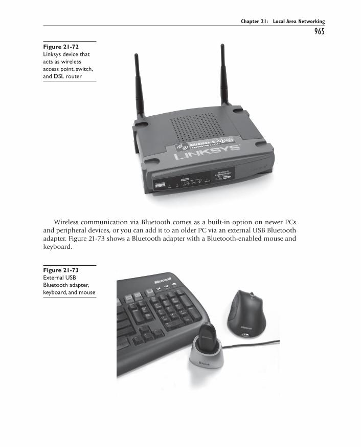
All-in-1 / A+ Certification Exm Gde, 6th Ed. / Meyers / 6311-3
Chapter 21: Local Area Networking
965
Wireless communication via Bluetooth comes as a built-in option on newer PCs and peripheral devices, or you can add it to an older PC via an external USB Bluetooth adapter. Figure 21-73 shows a Bluetooth adapter with a Bluetooth-enabled mouse and keyboard.
Figure 21-72 Linksys device that acts as wireless access point, switch, and DSL router
Figure 21-73 External USB Bluetooth adapter, keyboard, and mouse
ch21.indd 965ch21.indd 965 11/27/2006 10:25:21 AM11/27/2006 10:25:21 AM

All-in-1 / A+ Certification Exm Gde, 6th Ed. / Meyers / 6311-3
CompTIA A+ Certification All-in-One Exam Guide
966
EXAM TIP EXAM TIP The CompTIA A+ Essentials exam loves questions on cables and connectors, so look for questions on USB adapters and WAPs.
IT Technician
Wireless Networking SoftwareWireless devices use the same networking protocols and client that their wired counter-parts use, and they operate using the CSMA/CA networking scheme. The CA stands for collision avoidance, a slightly different standard than the collision detection standard used in wired Ethernet. Here’s the difference. Wireless nodes listen in on the wireless medi-um to see if another node is currently broadcasting data. If so, it waits a random amount of time before retrying. So far, this method is exactly the same as the method used by wired Ethernet networks. Because wireless nodes have a more difficult time detecting data collisions, however, they offer the option of using the Request to Send/Clear to Send (RTS/CTS) protocol. When enabled, a transmitting node that determines that the wire-less medium is clear to use sends an RTS frame to the receiving node. The receiving node responds with a CTS frame, telling the sending node that it’s okay to transmit. Then, once the data is sent, the transmitting node waits for an acknowledgment (ACK) from the receiving node before sending the next data packet. Very elegant, but keep in mind that using RTS/CTS introduces significant overhead to the process and can im-pede performance.
EXAM TIP EXAM TIP It’s tempting if you’re studying for the Help Desk or Depot Technician exams (Exams 220-603 and 220-604) to minimize the importance of wireless networking. This could come back to haunt you on the Essentials exam, though, so don’t skip this section!
In terms of configuring wireless networking software, you need to do very little. Wireless network adapters are plug and play, so any modern version of Windows will immediately recognize a wireless network adapter when installed into a PCI or PCMCIA slot, or a USB port, prompting you to load any needed hardware drivers. You will, however, need a utility to set parameters such as your Service Set Identifier (SSID), also called a network name.
Windows XP has built-in tools for configuring these settings, but for previous ver-sions of Windows, you need to rely on configuration tools provided by the wireless network adapter vendor. Figure 21-74 shows a typical wireless network adapter configu-ration utility. Using this utility, you can determine your link state and signal strength, configure your wireless networking mode (discussed next), and set security encryption, power saving options, and so on.
ch21.indd 966ch21.indd 966 11/27/2006 10:25:22 AM11/27/2006 10:25:22 AM
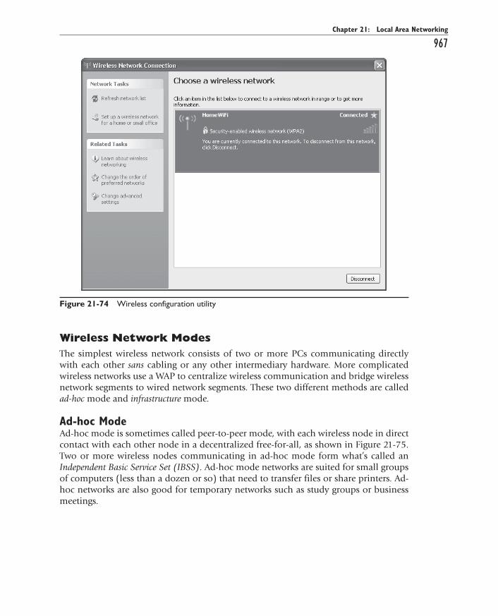
All-in-1 / A+ Certification Exm Gde, 6th Ed. / Meyers / 6311-3
Chapter 21: Local Area Networking
967
Wireless Network ModesThe simplest wireless network consists of two or more PCs communicating directly with each other sans cabling or any other intermediary hardware. More complicated wireless networks use a WAP to centralize wireless communication and bridge wireless network segments to wired network segments. These two different methods are called ad-hoc mode and infrastructure mode.
Ad-hoc ModeAd-hoc mode is sometimes called peer-to-peer mode, with each wireless node in direct contact with each other node in a decentralized free-for-all, as shown in Figure 21-75. Two or more wireless nodes communicating in ad-hoc mode form what’s called an Independent Basic Service Set (IBSS). Ad-hoc mode networks are suited for small groups of computers (less than a dozen or so) that need to transfer files or share printers. Ad-hoc networks are also good for temporary networks such as study groups or business meetings.
Figure 21-74 Wireless configuration utility
ch21.indd 967ch21.indd 967 11/27/2006 10:25:22 AM11/27/2006 10:25:22 AM
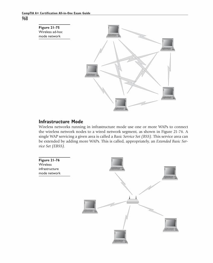
All-in-1 / A+ Certification Exm Gde, 6th Ed. / Meyers / 6311-3
CompTIA A+ Certification All-in-One Exam Guide
968
Infrastructure ModeWireless networks running in infrastructure mode use one or more WAPs to connect the wireless network nodes to a wired network segment, as shown in Figure 21-76. A single WAP servicing a given area is called a Basic Service Set (BSS). This service area can be extended by adding more WAPs. This is called, appropriately, an Extended Basic Ser-vice Set (EBSS).
Figure 21-75 Wireless ad-hoc mode network
Figure 21-76 Wireless infrastructure mode network
ch21.indd 968ch21.indd 968 11/27/2006 10:25:23 AM11/27/2006 10:25:23 AM

All-in-1 / A+ Certification Exm Gde, 6th Ed. / Meyers / 6311-3
Chapter 21: Local Area Networking
969Wireless networks running in infrastructure mode require more planning and are
more complicated to configure than ad-hoc mode networks, but they also give you finer control over how the network operates. Infrastructure mode is better suited to business networks or networks that need to share dedicated resources such as Internet connections and centralized databases. If you plan on setting up a wireless network for a large number of PCs or need centralized control over the wireless network, infrastruc-ture mode is what you need.
Wireless Networking SecurityOne of the major complaints against wireless networking is that it offers weak security. In many cases, the only thing you need to do to access a wireless network is walk into a WAP’s coverage area and turn on your wireless device! Further, data packets are float-ing through the air instead of safely wrapped up inside network cabling. What’s to stop an unscrupulous PC tech with the right equipment from grabbing those packets out of the air and reading that data himself?
Wireless networks use three methods to secure access to the network itself and se-cure the data that’s being transferred. The SSID (network name) parameter is used to define the wireless network—very handy when you have a number of wireless networks in the same area!
SSIDOne of the main security weaknesses with wireless networks is that, out of the box, there’s no security configured at all. Wireless devices want to be heard, and WAPs are usually configured to broadcast their presence to their maximum range and welcome all other wireless devices that respond.
Always change the default SSID to something unique. Configuring a unique SSID name is the very least that you should do to secure a wireless network. The default SSID names are well known and widely available online. This is intended to make setting up a wireless network as easy as possible, but conversely it creates a security hole you could drive a bullet train through. Each wireless network node and access point needs to be configured with the same unique SSID name. This SSID name is then included in the header of every data packet broadcast in the wireless network’s coverage area. Data packets that lack the correct SSID name in the header are rejected.
EXAM TIP EXAM TIP Changing the default SSID for the WAP is the first step in setting up a new wireless network.
Another trick often seen in wireless networks is to tell the wireless device to not broadcast the SSID. This makes it harder for people not authorized to access the net-work to know it’s there.
MAC FilteringMost WAPs also support MAC address filtering, a method that enables you to limit ac-cess to your wireless network based on the physical, hard-wired address of the units’ wireless NIC. MAC filtering is a handy way of creating a type of “accepted users” list to
ch21.indd 969ch21.indd 969 11/27/2006 10:25:23 AM11/27/2006 10:25:23 AM
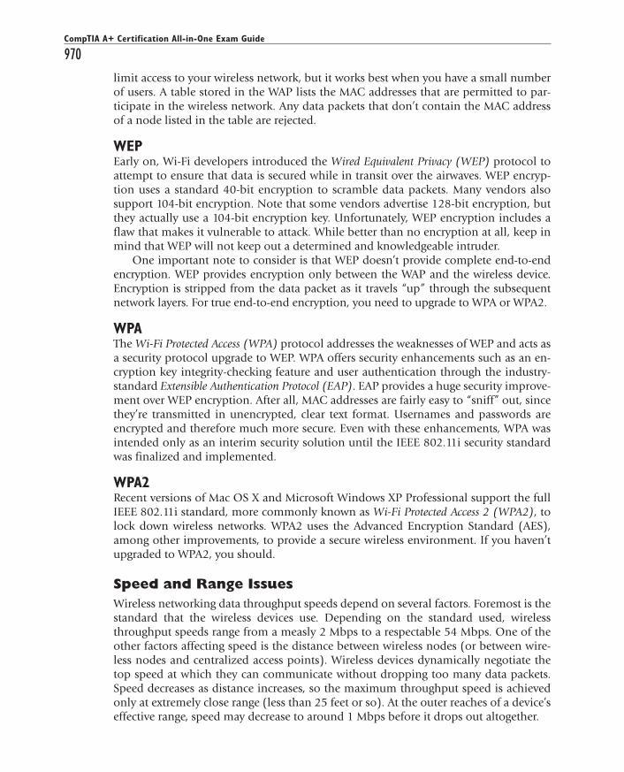
All-in-1 / A+ Certification Exm Gde, 6th Ed. / Meyers / 6311-3
CompTIA A+ Certification All-in-One Exam Guide
970limit access to your wireless network, but it works best when you have a small number of users. A table stored in the WAP lists the MAC addresses that are permitted to par-ticipate in the wireless network. Any data packets that don’t contain the MAC address of a node listed in the table are rejected.
WEPEarly on, Wi-Fi developers introduced the Wired Equivalent Privacy (WEP) protocol to attempt to ensure that data is secured while in transit over the airwaves. WEP encryp-tion uses a standard 40-bit encryption to scramble data packets. Many vendors also support 104-bit encryption. Note that some vendors advertise 128-bit encryption, but they actually use a 104-bit encryption key. Unfortunately, WEP encryption includes a flaw that makes it vulnerable to attack. While better than no encryption at all, keep in mind that WEP will not keep out a determined and knowledgeable intruder.
One important note to consider is that WEP doesn’t provide complete end-to-end encryption. WEP provides encryption only between the WAP and the wireless device. Encryption is stripped from the data packet as it travels “up” through the subsequent network layers. For true end-to-end encryption, you need to upgrade to WPA or WPA2.
WPAThe Wi-Fi Protected Access (WPA) protocol addresses the weaknesses of WEP and acts as a security protocol upgrade to WEP. WPA offers security enhancements such as an en-cryption key integrity-checking feature and user authentication through the industry-standard Extensible Authentication Protocol (EAP). EAP provides a huge security improve-ment over WEP encryption. After all, MAC addresses are fairly easy to “sniff” out, since they’re transmitted in unencrypted, clear text format. Usernames and passwords are encrypted and therefore much more secure. Even with these enhancements, WPA was intended only as an interim security solution until the IEEE 802.11i security standard was finalized and implemented.
WPA2Recent versions of Mac OS X and Microsoft Windows XP Professional support the full IEEE 802.11i standard, more commonly known as Wi-Fi Protected Access 2 (WPA2), to lock down wireless networks. WPA2 uses the Advanced Encryption Standard (AES), among other improvements, to provide a secure wireless environment. If you haven’t upgraded to WPA2, you should.
Speed and Range IssuesWireless networking data throughput speeds depend on several factors. Foremost is the standard that the wireless devices use. Depending on the standard used, wireless throughput speeds range from a measly 2 Mbps to a respectable 54 Mbps. One of the other factors affecting speed is the distance between wireless nodes (or between wire-less nodes and centralized access points). Wireless devices dynamically negotiate the top speed at which they can communicate without dropping too many data packets. Speed decreases as distance increases, so the maximum throughput speed is achieved only at extremely close range (less than 25 feet or so). At the outer reaches of a device’s effective range, speed may decrease to around 1 Mbps before it drops out altogether.
ch21.indd 970ch21.indd 970 11/27/2006 10:25:24 AM11/27/2006 10:25:24 AM

All-in-1 / A+ Certification Exm Gde, 6th Ed. / Meyers / 6311-3
Chapter 21: Local Area Networking
971Speed is also affected by interference from other wireless devices operating in the
same frequency range—such as cordless phones or baby monitors—and by solid ob-jects. So-called dead spots occur when something capable of blocking the radio signal comes between the wireless network nodes. Large electrical appliances such as refrig-erators are very effective at blocking a wireless network signal. Other culprits include electrical fuse boxes, metal plumbing, air conditioning units, and similar objects.
NOTE NOTE You can see the speed and signal strength on your wireless network by looking at the Wireless NIC’s properties.
Wireless networking range is difficult to define, and you’ll see most descriptions listed with qualifiers, such as “around 150 feet” and “about 300 feet.” This is simply be-cause, like throughput speed, range is greatly affected by outside factors. Interference from other wireless devices affects range, as does interference from solid objects. The maximum ranges listed in the next section are those presented by wireless manufactur-ers as the theoretical maximum ranges. In the real world, you’ll experience these ranges only under the most ideal circumstances. True effective range is probably about half what you see listed.
NOTE NOTE Range can be increased in a couple of ways. You can install multiple WAPs to permit “roaming” between one WAP’s coverage area and another’s—an EBSS, described earlier in this chapter. Or you can install a signal booster that increases a single WAP’s signal strength, thus increasing its range.
EXAM TIP EXAM TIP Look for basic troubleshooting questions on the CompTIA A+ certification exams dealing with factors that affect wireless connectivity, range, and speed.
Wireless Networking StandardsTo help you gain a better understanding of wireless network technology, here is a brief look at the standards that they use.
IEEE 802.11-Based Wireless NetworkingThe IEEE 802.11 wireless Ethernet standard defines methods by which devices may communicate using spread-spectrum radio waves. Spread-spectrum broadcasts data in small, discrete chunks over the different frequencies available within a certain frequen-cy range. All of the 802.11-based wireless technologies broadcast and receive at 2.4 GHz (with the exception of 802.11a, which uses 5 GHz). The original 802.11 standard has been extended to 802.11a, 802.11b, and 802.11g variations used in Wi-Fi wireless net-works, and also hybridized (combined with another wireless communication technol-ogy) to form the Shared Wireless Access Protocol (SWAP) used in the now defunct HomeRF networks.
ch21.indd 971ch21.indd 971 11/27/2006 10:25:25 AM11/27/2006 10:25:25 AM

All-in-1 / A+ Certification Exm Gde, 6th Ed. / Meyers / 6311-3
CompTIA A+ Certification All-in-One Exam Guide
972Wi-Fi is by far the most widely adopted wireless networking type today. Not only
do thousands of private businesses and homes have wireless networks, but many pub-lic places such as coffee shops and libraries also offer Internet access through wireless networks.
NOTE NOTE Technically, only wireless devices that conform to the extended versions of the 802.11 standard, 802.11a, 802.11b, and 802.11g, are Wi-Fi certified. Wi-Fi certification comes from the Wi-Fi Alliance (formerly the Wireless Ethernet Compatibility Alliance, or WECA), a nonprofit industry group made up of more than 175 member companies who design and manufacturer wireless networking products. Wi-Fi certification ensures compatibility among wireless networking devices made by different vendors. First-generation devices that use the older 802.11 standard are not Wi-Fi certified and may or may not work well with devices made by different vendors.
Wireless devices can communicate only with other wireless devices that use the same standard. The exception to this is 802.11g, which is backward compatible with 802.11b devices (although at the lower speed of 802.11b). The following paragraphs describe the important specifications of each of the popular 802.11-based wireless net-working standards.
NOTE NOTE Devices that use the original 802.11 (with no letter) standard are a rarity these days. You’re likeliest to find them in service on some brave early wireless adopter’s network. The original 802.11 standard was hampered by both slow speeds (2 Mbps maximum) and limited range (about 150 feet). 802.11 employed some of the same features that are in use in the current wireless standards. 802.11 uses the 2.4-GHz broadcast range, and security is provided by the use of industry-standard WEP, WPA, and WPA2 encryption.
802.11a Despite the “a” designation for this extension to the 802.11 standard, 802.11a was actually developed after 802.11b. The 802.11a standard differs from the other 802.11-based standards in significant ways. Foremost is that it operates in a dif-ferent frequency range, 5 GHz. This means that devices that use this standard are less prone to interference from other devices that use the same frequency range. 802.11a also offers considerably greater throughput than 802.11 and 802.11b at speeds up to 54 Mbps, though its actual throughput is no more than 25 Mbps in normal traffic condi-tions. While its theoretical range tops out at about 150 feet, in a typical office environ-ment, its maximum range will be lower. Despite the superior speed of 802.11a, it isn’t widely adopted in the PC world.
802.11b 802.11b is practically ubiquitous in wireless networking. The 802.11b stan-dard supports data throughput of up to 11 Mbps (with actual throughput averaging 4 to 6 Mbps)—on par with older wired 10BaseT networks—and a maximum range of 300 feet under ideal conditions. In a typical office environment, its maximum range will be lower.
ch21.indd 972ch21.indd 972 11/27/2006 10:25:25 AM11/27/2006 10:25:25 AM
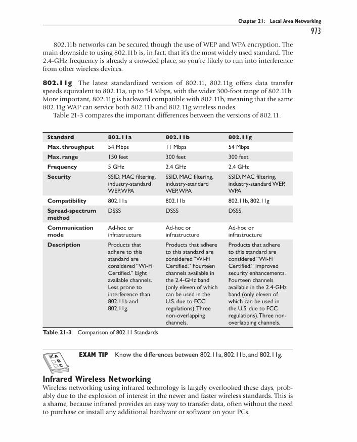
All-in-1 / A+ Certification Exm Gde, 6th Ed. / Meyers / 6311-3
Chapter 21: Local Area Networking
973802.11b networks can be secured though the use of WEP and WPA encryption. The
main downside to using 802.11b is, in fact, that it’s the most widely used standard. The 2.4-GHz frequency is already a crowded place, so you’re likely to run into interference from other wireless devices.
802.11g The latest standardized version of 802.11, 802.11g offers data transfer speeds equivalent to 802.11a, up to 54 Mbps, with the wider 300-foot range of 802.11b. More important, 802.11g is backward compatible with 802.11b, meaning that the same 802.11g WAP can service both 802.11b and 802.11g wireless nodes.
Table 21-3 compares the important differences between the versions of 802.11.
Standard 802.11a 802.11b 802.11g
Max. throughput 54 Mbps 11 Mbps 54 Mbps
Max. range 150 feet 300 feet 300 feet
Frequency 5 GHz 2.4 GHz 2.4 GHz
Security SSID, MAC filtering, industry-standard WEP, WPA
SSID, MAC filtering, industry-standard WEP, WPA
SSID, MAC filtering, industry-standard WEP, WPA
Compatibility 802.11a 802.11b 802.11b, 802.11g
Spread-spectrum method
DSSS DSSS DSSS
Communication mode
Ad-hoc or infrastructure
Ad-hoc or infrastructure
Ad-hoc or infrastructure
Description Products that adhere to this standard are considered “Wi-Fi Certified.” Eight available channels. Less prone to interference than 802.11b and 802.11g.
Products that adhere to this standard are considered “Wi-Fi Certified.” Fourteen channels available in the 2.4-GHz band (only eleven of which can be used in the U.S. due to FCC regulations). Three non-overlapping channels.
Products that adhere to this standard are considered “Wi-Fi Certified.” Improved security enhancements. Fourteen channels available in the 2.4-GHz band (only eleven of which can be used in the U.S. due to FCC regulations). Three non-overlapping channels.
Table 21-3 Comparison of 802.11 Standards
EXAM TIP EXAM TIP Know the differences between 802.11a, 802.11b, and 802.11g.
Infrared Wireless NetworkingWireless networking using infrared technology is largely overlooked these days, prob-ably due to the explosion of interest in the newer and faster wireless standards. This is a shame, because infrared provides an easy way to transfer data, often without the need to purchase or install any additional hardware or software on your PCs.
ch21.indd 973ch21.indd 973 11/27/2006 10:25:25 AM11/27/2006 10:25:25 AM

All-in-1 / A+ Certification Exm Gde, 6th Ed. / Meyers / 6311-3
CompTIA A+ Certification All-in-One Exam Guide
974Infrared Data Association Standard Communication through infrared de-vices is enabled via the Infrared Data Association (IrDA) protocol. The IrDA protocol stack is a widely supported industry standard and has been included in all versions of Windows since Windows 95.
NOTE NOTE Apple computers also support IrDA, as do Linux PCs.
Speed- and range-wise, infrared isn’t very impressive. Infrared devices are capable of transferring data up to 4 Mbps—not too shabby, but hardly stellar. The maximum dis-tance between infrared devices is 1 meter. Infrared links are direct line-of-sight and are susceptible to interference. An infrared link can be disrupted by anything that breaks the beam of light—a badly placed can of Mountain Dew, a co-worker passing between desks, or even bright sunlight hitting the infrared transceiver can cause interference.
Infrared is designed to make a point-to-point connection between two devices only in ad-hoc mode. No infrastructure mode is available. You can, however, use an infrared access point device to enable Ethernet network communication using IrDA. Infrared devices operate at half-duplex, meaning that while one is talking, the other is listen-ing—they can’t talk and listen at the same time. IrDA has a mode that emulates full-duplex communication, but it’s really half-duplex. Security-wise, the IrDA protocol offers exactly nothing in the way of encryption or authentication. Infrared’s main secu-rity feature is the fact that you have to be literally within arm’s reach to establish a link. Clearly, infrared is not the best solution for a dedicated network connection, but for a quick file transfer or print job without getting your hands dirty, it’ll do in a pinch.
Table 21-4 lists infrared’s important specifications.
Table 21-4 Infrared Specs
Standard Infrared (IrDA)
Max. throughput Up to 4 Mbps
Max. range 1 meter (39 inches)
Security None
Compatibility IrDA
Communication mode Point-to-point ad-hoc
BluetoothBluetooth wireless technology (named for 9th-century Danish king Harald Bluetooth) is designed to create small wireless personal area networks (PANs) that link PCs to periph-eral devices such as PDAs and printers, input devices such as keyboards and mice, and
ch21.indd 974ch21.indd 974 11/27/2006 10:25:26 AM11/27/2006 10:25:26 AM

All-in-1 / A+ Certification Exm Gde, 6th Ed. / Meyers / 6311-3
Chapter 21: Local Area Networking
975even consumer electronics such as cell phones, home stereos, televisions, home secu-rity systems, and so on. Bluetooth is not designed to be a full-function networking solu-tion, nor is it meant to compete with Wi-Fi. If anything, Bluetooth is poised to replace infrared as a means to connect PCs to peripherals.
The IEEE organization has made Bluetooth the basis for its forthcoming 802.15 standard for wireless PANs. Bluetooth uses the FHSS spread-spectrum broadcasting method, switching between any of the 79 frequencies available in the 2.45-GHz range. Bluetooth hops frequencies some 1600 times per second, making it highly resistant to interference. It transfers data from 723 Kbps to 1—count ’em, 1—Mbps, with a maxi-mum range of 10 meters (just over 30 feet). Some high-powered Bluetooth devices have throughput speed of a whopping 2 Mbps and a maximum range of up to 300 feet, but these are uncommon.
Bluetooth is not designed to be a full-fledged wireless networking solution. Blue-tooth is made to replace the snake’s nest of cables that currently connects most PCs to their various peripheral devices—keyboard, mouse, printer, speakers, scanner, and the like—but you won’t be swapping out your 802.11-based networking devices with Blue-tooth-based replacements anytime soon.
Having said that, Bluetooth-enabled wireless networking is comparable to other wireless technologies in a few ways:
• Like infrared, Bluetooth is acceptable for quick file transfers where a wired connection (or a faster wireless connection) is unavailable.
• Bluetooth’s speed and range make it a good match for wireless print server solutions.
Bluetooth Wireless Networking Hardware Bluetooth hardware comes ei-ther integrated into many newer portable electronic gadgets such as PDAs and cell phones or as an adapter added to an internal or external expansion bus. Bluetooth net-working is enabled through ad-hoc styled PC-to-PC (or PDA, handheld computer, or cell phone–to-PC) connections, or in an infrastructure-like mode through Bluetooth access points. Bluetooth access points are very similar to 802.11-based access points, bridging wireless Bluetooth PAN segments to wired LAN segments.
CellularCellular wireless networks enable you to connect to the Internet through a network-aware personal digital assistant (PDA) or cell phone. Figure 21-77 shows a higher end cell phone with an Internet connection. Using an add-on PC Card, you can connect any laptop to a cellular network as well. Figure 21-78 shows a Sprint Mobile Broad-band Card.
ch21.indd 975ch21.indd 975 11/27/2006 10:25:26 AM11/27/2006 10:25:26 AM

All-in-1 / A+ Certification Exm Gde, 6th Ed. / Meyers / 6311-3
CompTIA A+ Certification All-in-One Exam Guide
976
In areas with broad cell phone coverage, such as big cities, cellular wireless net-works offer high-speed access (400 to 700 Kbps download speeds) anywhere you go. Just fire up your device or portable and start surfing the Web! In remote areas, the speed drops down to something closer to modem connection speeds. (See Chapter 22, “The Internet,” for the scoop on modems.)
Figure 21-77 Sony-Erikson phone
Figure 21-78 Cellular network card
ch21.indd 976ch21.indd 976 11/27/2006 10:25:26 AM11/27/2006 10:25:26 AM

All-in-1 / A+ Certification Exm Gde, 6th Ed. / Meyers / 6311-3
Chapter 21: Local Area Networking
977Cellular networks use various protocols to connect, such as Global System for Mo-
bile Communications (GSM), General Packet Radio Service (GPRS), and Code Divi-sion Multiple Access (CDMA). These protocols are handled seamlessly by the software and hardware. What the end user sees is TCP/IP, just as if he or she connected through a wired network.
About the only real downside to cellular wireless networks is the price. The cell phone companies (notably Sprint and Cingular) are quite proud of their network ser-vice. As the technology matures, competition among the cellular network providers should bring the price down to something affordable for many people. At this point, though, it’s usually much more cost-effective to go to a coffee shop or library and con-nect via Wi-Fi.
Configuring Wireless NetworkingThe mechanics of setting up a wireless network don’t differ much from a wired net-work. Physically installing a wireless network adapter is the same as installing a wired NIC, whether it’s an internal PCI card, a PCMCIA card, or an external USB device. Sim-ply install the device and let plug and play handle detection and resource allocation. Install the device’s supplied driver when prompted, and you’re practically done. Unless you’re using Windows XP, you also need to install the wireless network configuration utility supplied with your wireless network adapter so that you can set your communi-cation mode, SSID, and so on.
As mentioned earlier, wireless devices want to talk to each other, so communicating with an available wireless network is usually a no-brainer. The trick is in configuring the wireless network so that only specific wireless nodes are able to use it and securing the data that’s being sent through the air.
Wi-FiWi-Fi networks support ad-hoc and infrastructure operation modes. Which mode you choose depends on the number of wireless nodes you need to support, the type of data sharing they’ll perform, and your management requirements.
Ad-hoc Mode Ad-hoc wireless networks don’t need a WAP. The only requirements in an ad-hoc mode wireless network are that each wireless node be configured with the same network name (SSID), and that no two nodes use the same IP address. Figure 21-79 shows a wireless network configuration utility with ad-hoc mode selected. Clicking the Initiate Ad Hoc button on this particular utility opened the Ad Hoc Setting dialog box where you can set the speed and the channel (if necessary.) Other utilities have the options in different dialog box, but a quick glance should find the same options.
ch21.indd 977ch21.indd 977 11/27/2006 10:25:27 AM11/27/2006 10:25:27 AM

All-in-1 / A+ Certification Exm Gde, 6th Ed. / Meyers / 6311-3
CompTIA A+ Certification All-in-One Exam Guide
978
The only other configuration steps to take are to make sure that no two nodes are using the same IP address (this step is usually unnecessary if all PCs are using DHCP) and to ensure that the File and Printer Sharing service is running on all nodes.
Infrastructure Mode Typically, infrastructure mode wireless networks employ one or more WAPs connected to a wired network segment, a corporate intranet or the Internet, or both. As with ad-hoc mode wireless networks, infrastructure mode net-works require that the same SSID be configured on all nodes and WAPs. Figure 21-80 shows the same NETGEAR Wi-Fi configuration screen, this time set to infrastructure mode and using WPA security.
Figure 21-79 Selecting ad-hoc mode in wireless configuration utility
Figure 21-80 Selecting infrastructure mode in wireless configuration utility
ch21.indd 978ch21.indd 978 11/27/2006 10:25:27 AM11/27/2006 10:25:27 AM

All-in-1 / A+ Certification Exm Gde, 6th Ed. / Meyers / 6311-3
Chapter 21: Local Area Networking
979WAPs have an integrated Web server and are configured through a browser-based
setup utility. Typically, you fire up your Web browser on one of your network client workstations and enter the WAP’s default IP address, such as 192.168.1.1, to bring up the configuration page. You will need to supply an administrative password, included with your WAP’s documentation, to log in (see Figure 21-81). Setup screens vary from vendor to vendor and from model to model. Figure 21-82 shows the initial setup screen for a popular Linksys WAP/router.
Figure 21-81 Security login for Linksys WAP
Figure 21-82 Linksys WAP setup screen
ch21.indd 979ch21.indd 979 11/27/2006 10:25:28 AM11/27/2006 10:25:28 AM

All-in-1 / A+ Certification Exm Gde, 6th Ed. / Meyers / 6311-3
CompTIA A+ Certification All-in-One Exam Guide
980Configure the SSID option where indicated. Channel selection is usually automatic,
but you can reconfigure this option if you have particular needs in your organization (for example, if you have multiple wireless networks operating in the same area). Re-member that it’s always more secure to configure a unique SSID than it is to accept the well-known default one. You should also make sure that the option to allow broadcast-ing of the SSID is disabled. This ensures that only wireless nodes specifically configured with the correct SSID can join the wireless network.
To increase security even more, use MAC filtering. Figure 21-83 shows the MAC filter-ing configuration screen on a Linksys WAP. Simply enter the MAC address of a wireless node that you wish to allow (or deny) access to your wireless network. Set up encryption by turning encryption on at the WAP and then generating a unique security key. Then configure all connected wireless nodes on the network with the same key information. Figure 21-84 shows the WPA2 key configuration dialog for a Linksys WAP.
Figure 21-83 MAC filtering configuration screen for a Linksys WAP
ch21.indd 980ch21.indd 980 11/27/2006 10:25:28 AM11/27/2006 10:25:28 AM
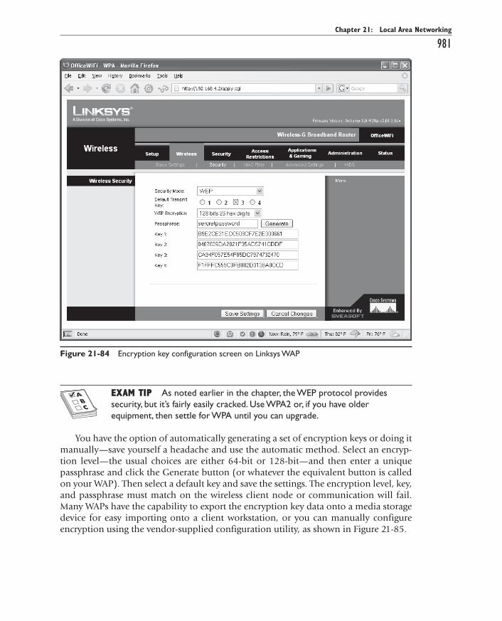
All-in-1 / A+ Certification Exm Gde, 6th Ed. / Meyers / 6311-3
Chapter 21: Local Area Networking
981
EXAM TIP EXAM TIP As noted earlier in the chapter, the WEP protocol provides security, but it’s fairly easily cracked. Use WPA2 or, if you have older equipment, then settle for WPA until you can upgrade.
You have the option of automatically generating a set of encryption keys or doing it manually—save yourself a headache and use the automatic method. Select an encryp-tion level—the usual choices are either 64-bit or 128-bit—and then enter a unique passphrase and click the Generate button (or whatever the equivalent button is called on your WAP). Then select a default key and save the settings. The encryption level, key, and passphrase must match on the wireless client node or communication will fail. Many WAPs have the capability to export the encryption key data onto a media storage device for easy importing onto a client workstation, or you can manually configure encryption using the vendor-supplied configuration utility, as shown in Figure 21-85.
Figure 21-84 Encryption key configuration screen on Linksys WAP
ch21.indd 981ch21.indd 981 11/27/2006 10:25:29 AM11/27/2006 10:25:29 AM

All-in-1 / A+ Certification Exm Gde, 6th Ed. / Meyers / 6311-3
CompTIA A+ Certification All-in-One Exam Guide
982
InfraredIrDA device support is very solid in the latest version of Windows—in fact, there’s not much for techs to configure. IrDA links are made between devices dynamically, without user interaction. Typically, there’s nothing to configure on an infrared-equipped PC. Check your network settings to ensure that you’ve got the IrDA protocol installed and enabled, and you should be good to go (see Figure 21-86).
Figure 21-85 Encryption screen on client wireless network adapter configuration utility
Figure 21-86 Confirming the presence of IrDA protocol in Windows Network settings
ch21.indd 982ch21.indd 982 11/27/2006 10:25:29 AM11/27/2006 10:25:29 AM
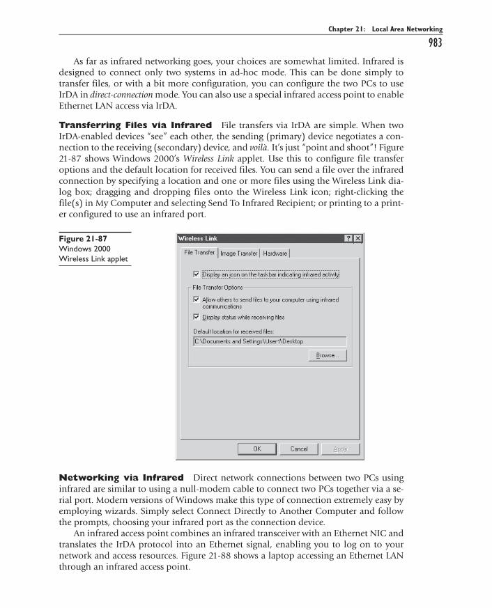
All-in-1 / A+ Certification Exm Gde, 6th Ed. / Meyers / 6311-3
Chapter 21: Local Area Networking
983As far as infrared networking goes, your choices are somewhat limited. Infrared is
designed to connect only two systems in ad-hoc mode. This can be done simply to transfer files, or with a bit more configuration, you can configure the two PCs to use IrDA in direct-connection mode. You can also use a special infrared access point to enable Ethernet LAN access via IrDA.
Transferring Files via Infrared File transfers via IrDA are simple. When two IrDA-enabled devices “see” each other, the sending (primary) device negotiates a con-nection to the receiving (secondary) device, and voilà. It’s just “point and shoot”! Figure 21-87 shows Windows 2000’s Wireless Link applet. Use this to configure file transfer options and the default location for received files. You can send a file over the infrared connection by specifying a location and one or more files using the Wireless Link dia-log box; dragging and dropping files onto the Wireless Link icon; right-clicking the file(s) in My Computer and selecting Send To Infrared Recipient; or printing to a print-er configured to use an infrared port.
Figure 21-87 Windows 2000 Wireless Link applet
Networking via Infrared Direct network connections between two PCs using infrared are similar to using a null-modem cable to connect two PCs together via a se-rial port. Modern versions of Windows make this type of connection extremely easy by employing wizards. Simply select Connect Directly to Another Computer and follow the prompts, choosing your infrared port as the connection device.
An infrared access point combines an infrared transceiver with an Ethernet NIC and translates the IrDA protocol into an Ethernet signal, enabling you to log on to your network and access resources. Figure 21-88 shows a laptop accessing an Ethernet LAN through an infrared access point.
ch21.indd 983ch21.indd 983 11/27/2006 10:25:29 AM11/27/2006 10:25:29 AM

All-in-1 / A+ Certification Exm Gde, 6th Ed. / Meyers / 6311-3
CompTIA A+ Certification All-in-One Exam Guide
984
Bluetooth Configuration As with other wireless networking solutions, Bluetooth devices are completely plug and play. Just connect the adapter and follow the prompts to install the appropriate drivers and configuration utilities (these are supplied by your hard-ware vendor). Once installed, you have little to do: Bluetooth devices seek each other out and establish the master/slave relationship without any intervention on your part.
Connecting to a Bluetooth PAN is handled by specialized utility software provided by your portable device or Bluetooth device vendor. Figure 21-89 shows a Compaq iPAQ handheld computer running the Bluetooth Manager software to connect to a Bluetooth access point. Like their Wi-Fi counterparts, Bluetooth access points use a browser-based configuration utility. Figure 21-90 shows the main setup screen for a Belkin Bluetooth access point. Use this setup screen to check on the status of connected Bluetooth devices; configure encryption, MAC filtering, and other security settings; and use other utilities provided by the access point’s vendor.
Figure 21-88 Laptop using infrared access point
Figure 21-89 iPAQ Bluetooth Manager software connected to Bluetooth access point
ch21.indd 984ch21.indd 984 11/27/2006 10:25:30 AM11/27/2006 10:25:30 AM

All-in-1 / A+ Certification Exm Gde, 6th Ed. / Meyers / 6311-3
Chapter 21: Local Area Networking
985
Troubleshooting NetworksOnce you go beyond a single PC and enter the realm of networked computers, your troubleshooting skills need to take a giant leap up in quality. Think of the complexity added with networks. Suddenly you have multiple PCs with multiple users who could, at the drop of a hat, do all kinds of inadvertent damage to a fully functional PC. Net-worked PCs have a layer of networked hardware and resource sharing that adds a com-pletely new dimension to a user’s cry for help, “I can’t print!”
EXAM TIP EXAM TIP The “Troubleshooting Networks” section covers a range of questions you’re likely to see on the “Communication and Professionalism” exam domain. See also Chapter 24, “The Complete PC Tech,” for more on the topic.
Where can the problem lie in a non-networked situation if a person cannot print? Here are the obvious ones:
• Printer is not connected to the PC.
• Printer is out of ink.
• PC doesn’t have the proper driver loaded.
• PC points by default to a printer other than the one to which the user thinks should print.
That’s about it. Maybe the parallel port configuration is wrong in CMOS or the USB drivers aren’t correct, but still.… Now do the same thing with a networked situation
Figure 21-90 Windows Bluetooth setup screen
ch21.indd 985ch21.indd 985 11/27/2006 10:25:30 AM11/27/2006 10:25:30 AM

All-in-1 / A+ Certification Exm Gde, 6th Ed. / Meyers / 6311-3
CompTIA A+ Certification All-in-One Exam Guide
986where a user can’t print. Here are the obvious extra issues, because all the local machine issues apply as well:
• Print server is down.
• Printer is locked by another user.
• The client PC doesn’t have network connectivity.
• The NIC driver is bad or incorrect.
• The client PC doesn’t have the proper printer drivers installed for the networked printer.
• The cable between the client PC’s NIC and the nearest switch is bad.
• The port to which the cable connects is bad.
• The switch failed.
• Somebody in an office down the hall spilled coffee on the printer inside the mechanism and then didn’t fess up to the accident.
That’s a lot of variables, and they just scratch the surface of possibilities. You live in a networked world—it’s time to elevate your troubleshooting skills and methodologies to the next level. This section offers a series of steps you can use when performing any type of PC or network troubleshooting. You’ll look at ways to apply your tech skills and gen-eral communication skills to get to the bottom of a problem and get that problem fixed.
Verify the SymptomThe one thing that all PC problems have in common is a symptom. If something odd was happening (or not happening) to users as they tried to do whatever they need to do on their computers, you wouldn’t have a problem at all, would you? Unfortunately, the vast majority of users out there aren’t CompTIA A+ certified technicians. As a tech, you need to overcome a rather nasty communication gap before you can begin to con-sider a fix. Let’s bridge that gap right now.
EXAM TIP EXAM TIP Look for lots of questions on communication with users on the IT Technician and Help Desk Technician exams.
It usually starts with a phone call:
You: “Tech Support, this is Mike. How can I help you?”
User: “Uh, hi, Mike. This is Tom over in Accounting. I can’t get into the network. Can you help me?”
Tom just started over in the Accounting department this week and has been a pain in the rear end so far. Ah, the things you might want to say to this person: “No. I only help non-pain-in-the-rear accountants.” Or how about this? “Let me check my appoint-ment schedule.… Ah, yes. I can check on your problem in two weeks. Monday at 4:00 P.M. okay for you?”
ch21.indd 986ch21.indd 986 11/27/2006 10:25:30 AM11/27/2006 10:25:30 AM

All-in-1 / A+ Certification Exm Gde, 6th Ed. / Meyers / 6311-3
Chapter 21: Local Area Networking
987But, of course, you had the audacity to choose the beloved profession of IT tech
support, so you don’t get to ask the questions you want to ask. Rather, you need to take a position of leadership and get to the bottom of the problem, and that means under-standing the symptom. Take a deep breath, smile, and get to work. You have two issues to deal with at this point. First, if you’re working with a user, you must try to get the user to describe the symptom. Second, whether you’re working on a system alone or you’re talking to a user on the telephone, you must verify that the symptom is legitimate.
Getting a user to describe a symptom is often a challenge. Users are not techs and as a result their perception of the PC is very different than yours. But by the same token, most users know a bit about PCs—you want to take advantage of a user’s skill and ex-perience whenever you can. A personal example of verifying the symptom: Once I got a call from a user telling me that his “screen was blank.” I told him to restart his system. To which he responded, “Shouldn’t I shut down the PC first?” I said: “I thought you just told me the screen was blank!” He replied: “That’s right. There’s nothing on the screen but my Desktop.”
When Did It Happen?Once you know the symptom, you need to try to inspect the problem yourself. This doesn’t mean you need to go to the system, as many real problems are easily fixed by the user, under your supervision. But you must understand when the problem occurs so that you can zero in on where to look for the solution. Does it happen at boot? It might be a CMOS/BIOS issue. Is it taking place as the OS loads? Then you need to start checking initialization files. Does it take place when the system runs untouched for a certain amount of time? Then maybe the power management could come into play.
What Has Changed?Systems that run properly tend to continue to run properly. Systems that have under-gone a hardware or software change have a much higher chance of not running prop-erly than a system that has not been changed. If something has gone wrong, talk to the user to determine whether anything particular has occurred since the system last worked properly. Has new software been installed? Did the user add some new RAM? Change the Windows Domain? Run a Windows Update? Drop the monitor on the floor? Not only do you need to consider those types of changes, you must make sure that any un-related changes don’t send you down the wrong path. The fact that someone installed a new floppy drive yesterday probably doesn’t have anything to do with the printer that isn’t working today.
Last, consider side effects of changes that don’t seem to have anything to do with the problem. For example, I once had a customer whose system kept freezing up in Windows. I knew he had just added a second hard drive, but the system booted up just fine and ran normally—except it would freeze up after a few minutes. The hard drive wasn’t the problem. The problem was that he unplugged the CPU fan in the process. When I discover a change has been made, I like to visualize the process of the change to consider how that change may have directly or indirectly contributed to a problem. In other words, if you run into a situation where a person added a NIC to a functioning
ch21.indd 987ch21.indd 987 11/27/2006 10:25:31 AM11/27/2006 10:25:31 AM

All-in-1 / A+ Certification Exm Gde, 6th Ed. / Meyers / 6311-3
CompTIA A+ Certification All-in-One Exam Guide
988PC that now won’t boot, you need to think about what part of the installation process could be fouled up to cause a PC to stop working.
Check the EnvironmentI use the term environment in two totally different fashions in this book. The first way is the most classic definition: the heat, humidity, dirt, and other outside factors that can affect the operation of the system. The other definition is more technical and addresses the computing environment of the user’s system and other surrounding systems: What type of system do they run? What OS? What is their network connection? What are the primary applications they use? What antivirus program do they run? Do other people use the system?
Answering these questions gives you an overview of what is affecting this system both internally and externally. A quick rundown of these issues can reveal possible problems that might not be otherwise recognized. For example, I once got a call from a user complaining they had no network connection. I first checked the NIC to ensure it had link lights (always the first thing to check to ensure a good physical connection!) only to discover that they had no link lights—someone decided to turn on a space heater which destroyed the cable!
Reproducing the ProblemMy official rule on problems with a PC is this: “If a problem happens only once, it is not a problem.” PCs are notorious for occasionally locking up, popping errors, and display-ing all types of little quirks that a quick reboot fixes, and they don’t happen again. Why do these things happen? I don’t know, although I’m sure if someone wanted me to guess I could come up with a clever explanation. But the majority of PCs simply don’t have redundancy built in, and it’s okay for them to occasionally “hiccup.”
A problem becomes interesting to me if it happens more than once. If it happens twice, there’s a much higher chance it will happen a third time. I want to see it happen that third time—under my supervision. I will direct the user to try to reproduce the problem while I am watching to see what triggers the failure. This is a huge clue to help-ing you localize the real problem. Intermittent failures are the single most frustrating events that take place in a technician’s life. But do remember that many seemingly in-termittent problems really aren’t intermittent—you have simply failed to reproduce the events exactly enough to see the consistency of the problem. Always take the time to match every step that leads to a problem to try to re-create the same error.
Isolating the SymptomWith so many bits and pieces to a PC, you must take the time to try to isolate the symp-tom to ensure your fix is going to the software or hardware that really needs it. In hard-ware, that usually means removing suspect parts until only one possible part remains. In software, that usually means removing background programs, booting into Safe Mode, or trying to create a situation where only the suspected program is running.
ch21.indd 988ch21.indd 988 11/27/2006 10:25:31 AM11/27/2006 10:25:31 AM

All-in-1 / A+ Certification Exm Gde, 6th Ed. / Meyers / 6311-3
Chapter 21: Local Area Networking
989Isolation takes on a whole new meaning with networks. One of the greatest tools in
networking is isolation—does this problem happen on other systems, on other work-groups, on other PCs running DHCP? Whenever a problem takes place in networking, isolation is the key to determining the problem.
Separating Hardware from SoftwareMany problems that occur on a PC are difficult to isolate given that it is difficult to determine whether the problem lies in the software or the hardware. If you find your-self in this situation, you can take a few steps to help you zero in on which side of the PC to suspect.
Known Good HardwareThe absolute best way to know whether a problem is hardware or software related is to replace the suspected piece of hardware with a known good part. If you can’t tell wheth-er a Windows page fault comes from bad RAM or a software incompatibility, quickly replacing the RAM with known good RAM should help you determine whether the RAM or the software is to blame.
Uninstall/ReinstallIf you can do so easily, try uninstalling the suspected software and reinstalling. Many hardware/software problems magically disappear with a simple uninstall/reinstall.
Patching/UpgradingMany hardware or software problems take place due to incompatibilities between the two suspect sides. Try upgrading drivers. Download patches or upgrades to software, especially if the hardware and the software are more than two years apart in age.
Virus CheckLast (maybe I should have put this first), always check for viruses. Today’s viruses man-ifest so many different symptoms that failure to check for them is a study in time wast-ing. I recently got a new hard drive that started to make a nasty clicking noise—a sure sign of a failing hard drive. However, I ran an extensive virus check and guess what—it was a virus! Who would have thought? I checked with the hard drive maker’s Web site, and my fears were confirmed. It just goes to show you—even the best of techs can get caught by the simplest problems.
ResearchOnce you’ve got your mind wrapped around the problem, it’s time to fix it. Unless the problem is either simple (network cable unplugged) or something you’ve seen before and know exactly how to fix, you’ll almost certainly need to research it. The Internet makes this easy. I use one of my favorite tricks when I get some bizarre error text: I type the error message into my search engine—that would be Google, of course—and most times find a quick fix!
ch21.indd 989ch21.indd 989 11/27/2006 10:25:31 AM11/27/2006 10:25:31 AM

All-in-1 / A+ Certification Exm Gde, 6th Ed. / Meyers / 6311-3
CompTIA A+ Certification All-in-One Exam Guide
990
Make the Fix and TestOnce you have a good idea as to the problem and how to fix it, it’s time to do the fix. Always make backups—or at least warn the user of the risk to the system. If possible, try to remember how the system was configured before the fix so that you can go back to square one if the fix fails to work. After you perform the fix, do whatever you need to do to make sure the system is again working properly. Make sure the user sees that the system is working properly so that he or she can “sign off” on your work.
OSI Seven-Layer ModelA lot of people think about networks and troubleshoot networking issues using the OSI seven-layer model. Using this model (or my four-layer model, described in the next section of this chapter) helps you isolate problems and then implement solutions. Here are the seven layers of the OSI model:
• Layer 1 Physical
• Layer 2 Data Link
• Layer 3 Network
• Layer 4 Transport
• Layer 5 Session
• Layer 6 Presentation
• Layer 7 Application
The Physical layer defines the physical form taken by data when it travels across a cable. Devices that work at the Physical layer include NICs, hubs, and switches. Figure 21-91 shows a sending NIC turning a string of ones and zeros into an electrical signal, and a receiving NIC turning it back into the same ones and zeros.
The Data Link layer defines the rules for accessing and using the Physical layer. MAC addresses and Ethernet’s CSMA/CD operate at the Data Link layer.
The Network layer defines the rules for adding information to the data packet that controls how routers move it from its source on one network to its destination on a different network. The IP protocol that handles IP addressing works on Layer 3.
The Transport layer, Layer 4, breaks up data it receives from the upper layers (that is, Layers 5–7) into smaller pieces for transport within the data packets created at the lower layers. In TCP/IP networks, the protocols that typically handle this transition between upper and lower layers are TCP and UDP.
ch21.indd 990ch21.indd 990 11/27/2006 10:25:32 AM11/27/2006 10:25:32 AM

All-in-1 / A+ Certification Exm Gde, 6th Ed. / Meyers / 6311-3
Chapter 21: Local Area Networking
991
The Session layer manages the connections between machines on the network. Pro-tocols such as NetBIOS and sockets enable a computer to connect to a server, for ex-ample, and send and receive e-mail or download a file. Each different task you can perform on a server would require a different kind of session.
The Presentation layer presents data from the sending system in a form that a receiv-ing system can understand. Most Layer 6 functions are handled by the same software that handles Layer 7 functions.
The Application layer is where you (or a user) get to interact with the computers. These are programs that make networking happen, such as Web browsers and e-mail applica-tions. Chapter 22, “The Internet,” covers these applications in a lot more detail.
The key to using the OSI seven-layer model is to ask the traditional troubleshooting question: What can the problem be? If Jill can’t browse a Web site, for example, could this be a Layer 7 issue? Sure: If her browser software was messed up, this could stop her from browsing. It could also be a lower level problem, though, and you need to run through the questions. Can she do anything over the network? If her NIC doesn’t show flashing link lights, that could point all the way down to the Physical layer and a bad NIC, cable, hub, or switch.
If she has good connectivity to the overall network but can’t ping the Web server, that could point to a different problem altogether. Figure 21-92 shows the OSI seven-layer model graphically.
Figure 21-91 The Physical layer turns binary code into a physical signal and back into ones and zeros.
ch21.indd 991ch21.indd 991 11/27/2006 10:25:32 AM11/27/2006 10:25:32 AM

All-in-1 / A+ Certification Exm Gde, 6th Ed. / Meyers / 6311-3
CompTIA A+ Certification All-in-One Exam Guide
992
The only drawback to the OSI seven-layer model, in my view, is that it’s too com-plex. I like to conceptualize network issues into fewer layers—four to be precise. Let’s take a look.
Mike’s Four-Layer ModelNetwork problems, by the very nature of the complexity of a network, usually make for more complex problems. Given that, I have created a four-step process that I modestly call “Mike’s Four-Layer Model.” These four things go through my mind every time I have a problem. I think about four distinct “categories” to help me isolate the symp-toms and make the right fix.
HardwareHardware is probably the most self-explanatory of the four categories. This covers the many different ways data can be moved from one PC to another. Does the system have a good connection—how’s the cabling? This also covers network cards—are they in-stalled properly and tested? Plus, the hardware category hits on all of those interesting boxes, such as hubs, switches, and repeaters, among which all of the wires in the net-work run. If you can see it, it’s under this category.
Figure 21-92 OSI
ch21.indd 992ch21.indd 992 11/27/2006 10:25:32 AM11/27/2006 10:25:32 AM

All-in-1 / A+ Certification Exm Gde, 6th Ed. / Meyers / 6311-3
Chapter 21: Local Area Networking
993
ProtocolsThis category covers the protocols, such as TCP/IP or NetBEUI. Is the protocol installed? Is it configured properly? Does any particular system’s configuration prevent it from working with another system?
NetworkThe network category has two parts: servers and clients. Network operating systems must differentiate systems that act as servers from those that do not. If a system is a server, some process must take place to tell it to share resources. Additionally, if a sys-tem is intended to share, it must be given a name. This category also includes defining and verifying users and groups—does your system need them? Do the right accounts exist, and are they working properly?
Shared ResourcesOnce all the systems, users, and groups are working properly, you need to identify the resources they will share. If a drive or folder is to be shared, the OS must provide a way to identify that drive or folder as available for sharing. The rules for naming shared re-sources are called naming conventions. A great example would be a system that offers its D:\FRED directory for sharing. This D:\FRED directory needs a network name, such as FRED_FILES. This network name is displayed to all of the devices on the network.
Sharing a resource is only half the battle. Individual systems need to be able to ac-cess the shared resources. The network needs a process whereby a PC can look out on the network and see what is available. Having found those available resources, the PC then needs to make them look and act as though they were local resources. A network also needs to control access to resources. A laser printer, for example, might be available for sharing, but only for the accounting department, excluding other departments.
Chapter Review Questions 1. To provide a computer with a physical and electronic connection to a
network, what must be installed?
A. A hub
B. A router
C. A NIC
D. A bridge
2. Which of the following is needed to configure a PnP NIC in a Windows XP system?
A. CMOS
B. Configuration software
C. Device driver
D. DMA
ch21.indd 993ch21.indd 993 11/27/2006 10:25:33 AM11/27/2006 10:25:33 AM

All-in-1 / A+ Certification Exm Gde, 6th Ed. / Meyers / 6311-3
CompTIA A+ Certification All-in-One Exam Guide
994 3. How far apart can two PCs that share the same 100BaseT switch be placed?
A. 100 meters
B. 200 meters
C. 330 meters
D. 1000 meters
4. Under ideal conditions, the 802.11g standard supports data throughput of up to ________ and has a range of up to ________.
A. 11 Mbps/150 feet
B. 11 Mbps/300 feet
C. 54 Mbps/150 feet
D. 54 Mbps/300 feet
5. What is the minimum specification of cable types for 100BaseT networks?
A. CAT 2
B. CAT 3
C. CAT 4
D. CAT 5
6. Joe needs to network two computers in his office together using an Ethernet peer-to-peer connection. What kind of cable does he need?
A. CAT-5
B. Crossover
C. UTP
D. STP
7. What are the two TIA/EIA standards for connecting an RJ-45 connector to UTP cable?
A. 10BaseT/100BaseT
B. CAT5/CAT5e
C. RG-58/RG-59
D. 568A/568B
8. Steven’s Windows XP system can’t connect to the Internet, and he comes to you, his PC tech, for help. You figure out that it’s a DHCP problem. What program should you run to get him a new DHCP lease?
A. IPCONFIG
B. WINIPCFG
C. CONFIG
D. DHCP /RENEW
ch21.indd 994ch21.indd 994 11/27/2006 10:25:33 AM11/27/2006 10:25:33 AM

All-in-1 / A+ Certification Exm Gde, 6th Ed. / Meyers / 6311-3
Chapter 21: Local Area Networking
995 9. Which encryption protocol offers the best security?
A. Hi-Encrypt
B. WEP
C. WPA
D. WPA2
10. Bluetooth technology enables computers to link into what sort of network?
A. Bluetooth area network (BAN)
B. Personal area network (PAN)
C. Local area network (LAN)
D. Wide area network (WAN)
Answers
1. C. A system must have a NIC to participate in any type of network.
2. C. PnP only requires the proper driver.
3. B. Each system can be 100 meters from the switch, so any two systems can be up to 200 meters apart.
4. B. Under ideal conditions, the 802.11g standard supports data throughput of up to 11 Mbps and has a range of up to 300 feet.
5. D. 100BaseT requires CAT 5 rated cabling.
6. B. Joe needs a crossover cable to network two computers in his office together using an Ethernet peer-to-peer connection.
7. D. The TIA/EIA has two standards for connecting the RJ-45 connector to the UTP cable: TIA/EIA 568A and TIA/EIA 568B.
8. A. You should run IPCONFIG to get a new DHCP lease for Steven’s Windows XP system. WINIPCFG was the program used by Windows 9x for this task. /RENEW is a valid switch for both programs, but not for CONFIG.
9. D. WPA2 is the best of the encryption technologies listed.
10. B. Bluetooth creates personal area networks.
ch21.indd 995ch21.indd 995 11/27/2006 10:25:33 AM11/27/2006 10:25:33 AM