chapter one - shodhgangashodhganga.inflibnet.ac.in/bitstream/10603/77978/8/08 _chapter 1.pdf ·...
TRANSCRIPT

Chapter One
Introduction to Ballistics

Chapter1
2
CHAPTER ONE
Introduction to Ballistics
This chapter is only an introduction to the vast subject of ballistics. It
does not deal in advanced theory but does contain material in modest details.
In this chapter, ballistics is discussed in three separate phases:
a. Internal Ballistics: This concerns the events that take place from charge
ignition to the moment when the projectile leaves the muzzle.
b. External Ballistics: This deals with the motion of the projectile from the
moment of leaving the muzzle to the moment of impact or burst.
c. Terminal Ballistics: This deals with the motion of the projectile and parts
or fragments thereof, from the moment of impact or burst.
For a short period of time after the projectile leaves the muzzle, the projectile
is acted upon by the pressure of the emerging gas. This is known as the
transitional phase of ballistics (sometimes referred to as intermediate
ballistics). Its effect must be taken into account during the design and
construction of the equipment when such factors as the functioning of the
weapon, the steadiness and stability of the gun and the use of a muzzle brake
are considered.
Applications of Ballistics
Gunnery is the practical application of the science of ballistics to the
engagement of targets. It is applicable to the engagement of targets and to the
reduction of data obtained by shooting to a form suitable for the eventual re-
engagement of targets. While the appropriate data can be arrived at by use of a
Proforma through a rather mechanical process, knowledge of ballistics and

Chapter1
3
ammunition characteristics will allow an understanding of the process being
followed.
1.1 Internal Ballistics
Internal ballistics is defined as the science that deals with the events that
take place in a gun from the moment the propellant charge is ignited until the
projectile leaves the muzzle. It deals with the complicated events during
burning of the propellant and the movement of the projectile, which in turn
depends on the design of the bore and the gas pressure. The task of the events
under consideration is to give the projectile the correct muzzle velocity and
the required rate of spin. In spite of numerous and detailed studies on the
subject, no exact scientific solution to the problem has yet been found. The
internal ballistics in this chapter relate to events as they pertain to the gun only
and no attempt has been made to relate these events to the mortar.
The evolution of heat and gases causes the temperature and pressure to
build up. Thermodynamic principles can be applied to find the relation
between the temperature and pressure, the physical properties of the products
of combustion, and the amount of heat released [1-2]. According to the first
Law of thermodynamics, the heat added, to a system is the sum (of the change
in its internal energy and the work done by the system
Q = ∆E + w (1-1)
Let the system consist of unit mass of propellant burned to its final products
in the free space of the gun chamber . The internal energy E can be given as
E = cvT0
0dT (1-2)
and if Q is the amount of heat related at constant volume (so that w = 0) ,

Chapter1
4
Q = cvT0
0dT − cv
T
0dT = cv
T0
T0′ dT (1-3)
where T0′ is the temperature of the products corresponding to their initial state,
T0 the temperature of the products (the Adiabatic flame temperature), cv is
the specific heat at constant volume. The pressure can be obtained from the
equation of state of the product gases. Using a form of the Van der Waals
equation of state:
P(τ − b) = nRT , P = nRT/(τ − b) (1-4)
where τ = τc − τp it τc is chamber volume , τp is propellant volume, and
τp = c/ρis the charge mass divided by the propellant density, vc is the molar
volume at critical point and b=vc/3 .
The projectile is accelerated by the pressure acting on the base of the
Projectile AP1 = mdv
dt (1-5)
where P1 is the pressure at the base of the projectile, A is the projectile cross-
sectional area, m is the projectile mass, and v is the projectile velocity. If the
pressure were known as a function of the displacement of the projectile as
shown in Fig.1, the muzzle velocity could be calculated directly and the
central problem of interior ballistics would be solved. Unfortunately, interior
ballistics investigations have not found any explicit dependence of pressure on
projectile displacement, but rather show that the pressure depends on the
amount of propellant burned behind the projectile and on the volume of the
space behind the projectile. The relation between pressures, the amount of
charge burned, and the change in volume brought about by projectile
displacement is derived from conservation of energy. This relation is called
Resal's equation.

Chapter1
5
1.1.1Resal's Equation
Let z be the fraction of the charge mass C that is burned at a given
instant; then (where J is the mechanical equivalent of heat)
E = JCz cvT0
0dT (1-6)
is the internal energy of the combustion products if there is no work done by
the system. Projectile displacement means that (1) the gases have expanded
and changed the internal energy and (2) the gases have done work. The
Fig. 1: Velocity and Pressure on the Base of a Projectile as a Function of
Distance along the Bore [Ref.3].
expansion of the gases lowers the temperature from T0 to T , and the internal
energy is E = JCz cvT
0dT (1-7)
The change in the internal energy is
∆E = JCz cvT
0dT − JCz cv
T0
0dT = −JCz cv
T0
TdT (1-8)
from Eq. 1-5 and 1-6, and the work of expansion is
w = A P1x
0dx (1-9)

Chapter1
6
(It is implicit in the thermodynamic assumptions that, P is uniform over the
chamber. The fact that this is only approximately true will be considered later)
Using the first law of thermodynamics and Eq. 1-7 and 1-8,
−∆E = w thus JCz cvT0
TdT = A P1
x
0dx (1-10)
It is usually assumed that the variation in cv , over the range from T to T0 is
small so that cv can be replaced under the integral sign by its mean value cv ;
hence, Eq. 1-10 becomes
JCzcv T0 = JCzcv T + A P1x
0dx (1-11)
and T is replaced by using an equation of state
P τ − b = nRT (1-12)
so that JCzcv T0 =Jcv cP τ−b
nR + A P1
x
0dx (1-13)
Use the thermodynamic relation cP − cv = nR/J and the definition of the
force constant, F = nRT0 , which is common in internal ballistics, to obtain
FCz
γ−1=
PCz τ−b
γ−1+ A P1
x
0dx
Where cP is the specific heat at constant pressure , τ is the volume occupied
by the unit mass of gas , γ = cP/cv , Czτ is the volume of gas at the time
considered and consists of these parts: chamber volume (τc) plus volume of
bore behind the projectile (Ax) minus the volume of propellant burned at the
given time (C(1 − z)/ρp ). The initial volume of the free space is expressed
for analytical Convenience as added length of bore l0 ,
Al = τc − C/ρp
and the final result is Resal's equation
FCz
γ−1=
P
γ−1A x + l0 − Cz
b−1
ρp+ A P1
x
0dx (1-14)
Chapter1
7
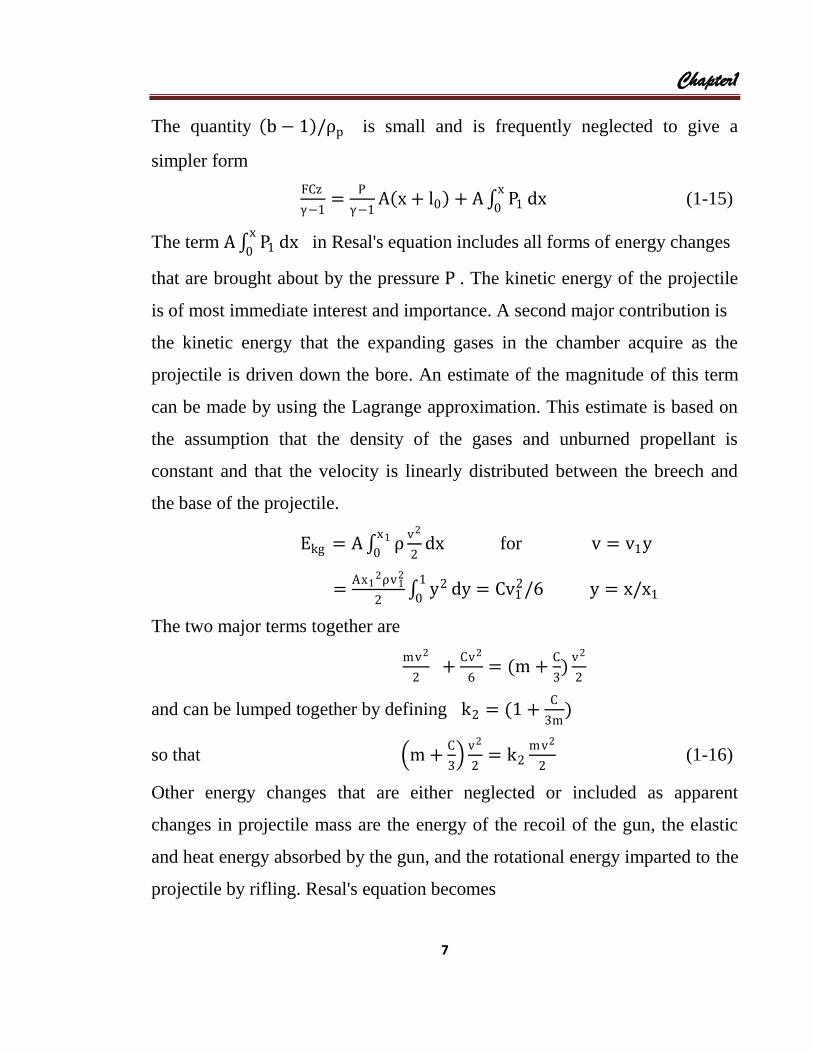
The quantity b − 1 /ρp is small and is frequently neglected to give a
simpler form
FCz
γ−1=
P
γ−1A x + l0 + A P1
x
0dx (1-15)
The term A P1x
0dx in Resal's equation includes all forms of energy changes
that are brought about by the pressure P . The kinetic energy of the projectile
is of most immediate interest and importance. A second major contribution is
the kinetic energy that the expanding gases in the chamber acquire as the
projectile is driven down the bore. An estimate of the magnitude of this term
can be made by using the Lagrange approximation. This estimate is based on
the assumption that the density of the gases and unburned propellant is
constant and that the velocity is linearly distributed between the breech and
the base of the projectile.
Ekg = A ρv2
2
x1
0dx for v = v1y
=Ax1
2ρv12
2 y21
0dy = Cv1
2/6 y = x/x1
The two major terms together are
mv2
2 +
Cv2
6= (m +
C
3)
v2
2
and can be lumped together by defining k2 = (1 +C
3m)
so that m +C
3
v2
2= k2
mv2
2 (1-16)
Other energy changes that are either neglected or included as apparent
changes in projectile mass are the energy of the recoil of the gun, the elastic
and heat energy absorbed by the gun, and the rotational energy imparted to the
projectile by rifling. Resal's equation becomes

Chapter1
8
FCz
γ−1=
P
γ−1A x + l0 +
k2mv2
2 (1-17)
The equation of motion of the projectile has to be supplemented by
information on the dependence of the pressure at the base of the projectile on
the displacement of the projectile down the bore. Resal's equation partially
fulfills this need. It is a relation between projectile velocity, the pressure, the
amount of charge that has been burned, and the change in volume brought
about by projectile displacement. To complete the required information, the
dependence of burning on the pressure and temperature within the barrel must
be determined.
In the discussion of warheads the properties of the flame front of a
propellant will be compared to the properties of the detonation front of a high
explosive. In Anticipation of that comparison it should be noted that the flow
of material in the burning of propellant; is in the opposite direction to the
advance of the flame front. In detonation the motion of reacted material is in
the same direction as the advance of the detonation front.
Many test; on the burning of propellants indicate that the rate of
advance of the propellant depends on the pressure. The form of the
mathematical relation that holds for many materials is
𝑑𝜉
𝑑𝑡= 𝑎𝑃0
𝑏 (1-18)
where 𝜉 is the displacement of the flame front, 𝑃0 is the pressure at the breech
where the propellant is burned, and 𝑎 and 𝑏 are empirical constants. This
equation is referred to as Vieille's law.
It is usually assumed that the reaction of the propellant is initiated on the
entire surface of all the propellant grains and advances into the grain parallel to

Chapter1
9
the grain surface. The law that propellants burn parallel to the initial grain
surface surface is called Piobert's law. Although it may not be accurate in
minute detail, it is believed to be a reasonable description of the net effect of
burning. Piobert's law is the basis for analytical expressions of the relation
between the rate of chemical reaction and the grain shape and size.
It is convenient to express the burning rate in terms of the fraction 𝑓 of
a typical grain dimension (𝜉 = 𝑓𝑑𝑔 ), since this is a parameter that must
ultimately be considered.
Thus 𝑑𝜉
𝑑𝑡= 𝑑𝑔
𝑑𝑓
𝑑𝑡= 𝑎𝑃0
𝑏 (1-19)
A particular expression that is used frequently is
𝑧 = 1 − 𝑓 (1 + Ө𝑓) (1-20)
which is called the form function. Ө = Ө(𝑓), and the particular analytical
expression of Ө represents the effect of shape.
The following sections discuss three propellants (powder) grain
configurations: cylindrical, tubular, and multi-tubular [Fig. 2].
Cylindrical Grain
A very simple grain configuration is a cylindrical grain (Fig.2a). The
volume of the cylinder is
𝜏0 = 𝜋𝑑𝑔2𝑙/4 , 𝜏0 = 𝜋𝑑𝑔
3𝜆/4
where 𝑑𝑔 is the diameter of the cylinder and 𝑙 is the length of the cylinder
(let 𝑙 = 𝜆𝑑𝑔).
The dimensions of the cylinder are reduced by 𝑓𝑑𝑔 at a given time. Since
𝑧 =𝑚𝑔0−𝑚0
𝑚𝑔0=
𝜏0−𝜏
𝜏0

Chapter1
10
and 𝜏 = 𝜋𝜆𝑓2𝑑𝑔 2 [𝑑𝑔 − 1 − 𝑓 𝑑𝑔]
then 𝑧 = 1 − 𝑓 [1 + (1 + 𝑓/𝜆)𝑓]
and Ө = 1 + 𝑓/𝜆
and for 𝜆 ≫ 1 Ө = 1
The burning surface of powder with this shape decreases as burning proceeds,
and the powder is called a digressive powder.
(a) Cylindrical grain (b) Tubular grain. (c) Multitubular grain
(d is the thickness of the wall)
Fig.2: Propellant Grains.
Tubular Grain
For a tubular grain [Fig.2b] the same types of considerations yield the
following equations for the initial and current volumes
𝜏0 = 2𝜋𝑑𝑔𝑟𝑙 , 𝜏0 = 2𝜋𝑑𝑔𝑟𝜆𝑑
and 𝑧 = 1 − 𝑓(𝜆 − 1 + 𝑓)/𝜆
= (1 − 𝑓)(1 + 𝑓/𝜆)
and = 1 − 𝑓 (if 𝜆 ≫ 1 and Ө = 0)
The burning surface of powder with this shape remains essentially constant as
burning proceeds, and the powder is called a neutral powder.
Multitubular Grain
Another common grain configuration is a cylinder with multiple
perforations [Fig.2c]. Ө for a seven-perforation grain is estimated at -0.172.

Chapter1
11
The burning surface continually increases as burning proceeds, and the
powder is called a progressive powder.
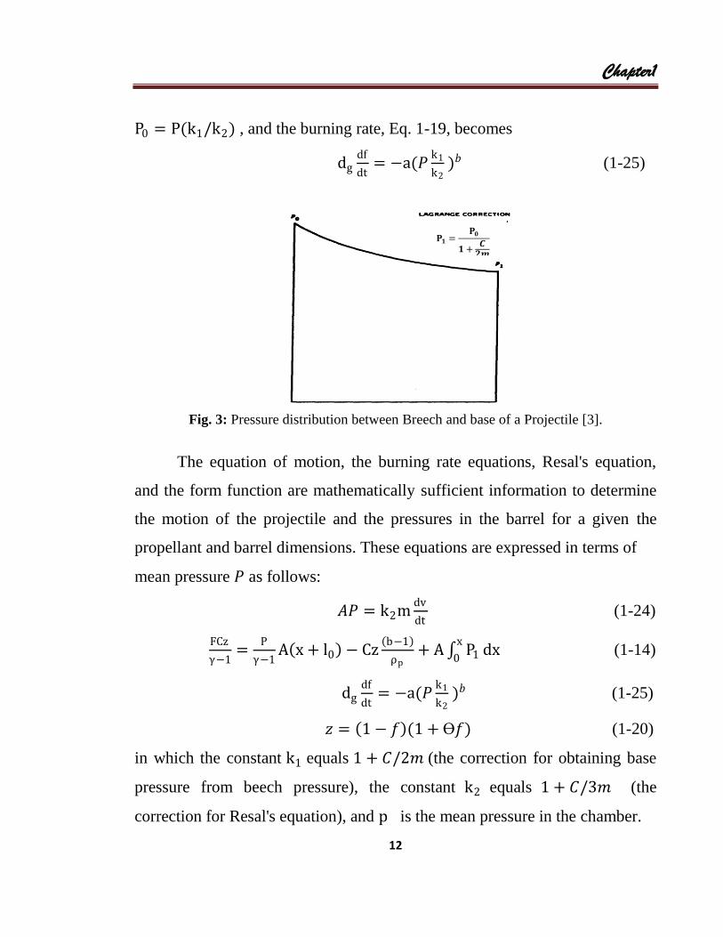
1.1.2 Lagrange Correction
The pressure behind the projectile cannot be uniform since there is a
positive velocity gradient from the breech to the base of the projectile; so the
pressure gradient must be negative. The pressure at the base of the projectile is
estimated by using a factor called a Lagrange correction for converting breech
pressure to base pressure [Fig.3]. This correction is derived by assuming that
pressure will drop in proportion to the momentum acquired by the propellant
gases. Specifically it is assumed that P1
P0=
𝑚𝑣
(𝑚+𝐶
2)𝑣
(1-21)
where 𝐶𝑣/2 is the momentum of the propellant gases estimated by using the
same assumptions employed in estimating the energy of the gases in the
discussion of the corrections to Resal's equation. Thus,
P1 =P0
1+𝐶
2𝑚
= P0/k1 where k1 = 1 +𝐶
2𝑚 (1-22)
A mean value of pressure 𝑃 is used in the internal energy term of
Resal's equation. This is estimated by assuming that the ratio of the pressure at
the base of the projectile to the mean pressure is equal to the ratio of the
projectile kinetic energy to the sum of the projectile and gas kinetic energies
P1
p=
𝑚𝑣2/2
𝑚+𝐶
2 (𝑣2/2)
(1-23)
so that P = P1k2 where k2 is defined by Eq. 1-16. Equation 1-5 is expressed
in terms of the mean pressure as AP = k2mdv
dt (1-24)
The pressure at the breech is found by using Eq. 1-22 and 1-23 to give
Chapter1
12
P0 = P(k1/k2) , and the burning rate, Eq. 1-19, becomes
dgdf
dt= −a(𝑃
k1
k2 )𝑏 (1-25)
Fig. 3: Pressure distribution between Breech and base of a Projectile [3].
The equation of motion, the burning rate equations, Resal's equation,
and the form function are mathematically sufficient information to determine
the motion of the projectile and the pressures in the barrel for a given the
propellant and barrel dimensions. These equations are expressed in terms of
mean pressure 𝑃 as follows:
𝐴𝑃 = k2mdv
dt (1-24)
FCz
γ−1=
P
γ−1A x + l0 − Cz
b−1
ρp+ A P1
x
0dx (1-14)
dgdf
dt= −a(𝑃
k1
k2 )𝑏 (1-25)
𝑧 = 1 − 𝑓 (1 + Ө𝑓) (1-20)
in which the constant k1 equals 1 + 𝐶/2𝑚 (the correction for obtaining base
pressure from beech pressure), the constant k2 equals 1 + 𝐶/3𝑚 (the
correction for Resal's equation), and p is the mean pressure in the chamber.
𝐏𝟏 =𝐏𝟎
𝟏 +𝑪
𝟐𝒎
Chapter1
13
These four equations are four separate and independent restrictions on
changes in pressure, velocity, and fraction of the charge that is burned as the
projectile moves down the barrel. The difficulties at this point are largely
mathematical the problem of extracting the required information in convenient
form.
Two of these equations can be simplified to give (Eqns. 1-17 and 1-19)
FcCz = PA 𝑥 + l0 (1-17a)
in which kinetic energy is deleted. and
dgdf
dt= −a𝑃
k1
k2 (1-19a)
which is the linear form, b = 1 . Equations 1-17a and 1-19a are reasonably
accurate in the early stages of projectile acceleration and are easier to solve.
Equations 1-24 and 1-19a are satisfied by
𝑣 = 𝐴dg(1 − 𝑓)/ak1m (1-26)
Equations 1-26. 1-17, and 1-17a imply
𝑑𝑥
𝑑𝑓=
A2dg 2 ( 𝑥+l0)
ma2 1+Ө𝑓 (1-27)
which has the solution
𝑥 + l0 = l0(1+Ө
1+Ө𝑓)G/Ө Ө ≠ 0 (1-28a)
and 𝑥 + 𝑙0 = 𝑙0exp[G 1 − f ] Ө = 0 (1-28b)
where G =A2dg
2 k2
mk1a2CFc (1-29)
The pressure is also found as a function of f from the above equations for
x + 1 and from Eq. 1-17a
P =Fc Ck1 1−𝑓 1+Ө𝑓
𝐴 l0k2(
1+𝑓
1+Ө)G/Ө Ө ≠ 0 (1-30a)

Chapter1
14
P =Fc Ck1 1−𝑓 exp [−G 1−f ]
𝐴 l0k2 Ө = 0 (1-30b)
These equations are sufficient to calculate the pressure as a function of
projectile displacement. In general the pressure peaks before the propellant is
used up and the pressure curve has a rounded top, but this depends on the
constants of the system, and the propellant may be used up on the ascending
part of the curve (Fig. 4).
Fig.4: Maximum Pressure Compared to Location of Burnout [3].
At f = 0 all of the propellant is burned, and the values of P , x and
are ; 𝑣b =𝐴dg
ak1m (1-31)
Pb =Fc Ck1
𝐴k2(1+Ө)G /Ө Ө ≠ 0 (1-32a)
Pb =Fc Ck1exp (G)
𝐴k2 Ө = 0 (1-32b)
𝑥b + l0 = l0(1 + Ө)G/Ө Ө ≠ 0 (1-33a)
𝑥b + l0 = l0exp(G) Ө = 0 (1-33b)
PMAX before Burnout
PMAX after Burnout
PMAX at Burnout

Chapter1
15
1.1.3 Projectile Acceleration after Burning
After burning is completed, z is equal to 1, and only two of the original
four equations apply to the phenomena; thus for z = 1 . Eq. 1.17 is
Fc C
γ−1=
PA x+l0
γ+1+
k2m𝑣2
2 (1-34)
and using dv/dt = v(dv/dx) Eq. 1-24 is
k2m𝑣d𝑣
d𝑥= 𝐴𝑃 (1-35)
These equations can be solved by differentiating Eq. 1-34 and eliminating 𝑣
from the result, using Eq. 1-35, so that
𝑑𝑃𝐴 x + l0 + 𝑃𝐴𝑑𝑥 + (γ − 1)k2m𝑣𝑑𝑣 = 0
𝑑𝑃𝐴 x + l0 + 𝑃𝐴𝑑𝑥 + (γ − 1)𝐴𝑃𝑑𝑥 = 0 (1-36)
which has the solution 𝑃 = Pb(x+l0
𝑥b +l0)γ (1-37)
Resal's equation after burning is
Fc C
γ−1= PbA 𝑥b + l0 +
k2m𝑣b2
2= PA(𝑥 + l0)
k2m𝑣2
2 (1-38)
This equation can be combined with the previous result for 𝑃𝑏 and 𝑥𝑏 + 𝑙 to
determine 𝑣 as a function of 𝑥 and system parameters,
𝑣2 = 𝑣b2 +
2Fc C
mk 2(γ−1)[1 − (
x+l0
𝑥b +l0)1−γ] (1-39)
From the definition of 𝐺 and 𝑣𝑏
𝑣b2 =
GC Fc
mk2 (1-40)
and 𝑣2 =Fc C
mk2[G +
2
γ−1[1 − (
x+l0
𝑥b +l0)1−γ]] (1-41)
The general shapes of pressure/distance curves for different types of powders
are compared in Fig. 5. The advantages of a progressive powder are shown in
this figure. For the limitation placed on the pressure/distance curve by the

Chapter1
16
strength of the barrel, the progressive powder may give the greatest muzzle
velocity. Small arms and cannon up to 20 mm usually use single-perforation
grains, and all larger guns use multi-perforated grains.
Fig. 5: Pressure/Distance Curves for Different Forms of Propellant [3].
An example of a specific pressure/distance curve is shown in Fig. 6.
Fig.7 compares a calculation of the pressure and velocity curves obtained for
instantaneous burning with that for the same powder burned gradually. This
comparison is interesting since the instantaneous burning is like the process of
energy release in a warhead. It will be noted that the instantaneous burning
gives the greater velocity (but at the price of very high pressures at the start of
the process). The velocity/distance curve for instantaneous burning [5] is
given by 𝑣 = 𝑣lim 1 − (x+l0
l0)1−γ (1-42)
which is Eqn. 39 with 𝑣𝑏 = 0 , 𝑥𝑏 = 0 and
𝑣lim = 2Fc C/(γ−1)
mk2 (1-43)

Chapter1
17
Fig. 6: Pressure Distance Curve for a Fig. 7: Pressure/Distance Curve for
3.7-Inch Antiaircraft Gun [3] Instantaneous Burning [3]
Examples of muzzle velocities for, several weapons are given below [3]
Weapon
Muzzle velocity,
ft/sec
240-mm howitzer M1
155-mm gun M1
105.mm howitzer M2
105-mm howitzer M2A1
75-mm gun M3
1,50 to 2,300
2,745
650
1,235 to 1,550
2,030
240-mm howitzer M1 155-mm gun M1

Chapter1
18
105.mm howitzer M2 105-mm howitzer M2A1
1.2 External Ballistics
External ballistics is the science that deals with the motion of a
projectile from the moment it leaves the muzzle of a gun to the moment of
impact or burst. The path followed by the projectile after ejection is called the
trajectory. Its form depends primarily on:
(i) muzzle velocity
(ii) angle of departure
(iii) Gravity
(iv) air resistance,
(v) weight and shape of the projectile,
(vi) spin of the projectile, and
(vii) Rotation of the earth.
Once the muzzle velocity and angle of departure have been decided, the two
main external influences on the projectile are gravity and air resistance. The
study of the motion of the projectile under the influence of gravity alone is
called motion in a vacuum and the results obtained are useful because of
certain similarities between the trajectory in air and the trajectory in a vacuum.

Chapter1
19
1.2.1 Motion in a Vacuum
The motion of a projectile in a vacuum is free of the effects of air
resistance. Consider a projectile fired at a particular angle of elevation (ø) and
muzzle velocity. Newton's first law of motion states that a body in motion
continues to move in a straight line at a constant velocity unless acted upon by
an external force. This means that were it not for gravity, the projectile would
continue along the line of departure to infinity. This does not happen, of
course, because the vertical component of velocity of the projectile will be
retarded by gravity until it reaches zero velocity at the vertex, and then the
projectile will fall back to earth under the acceleration of gravity [3].
1.2.2 Vacuum Trajectories
The basic equations for a ballistic trajectory in a vacuum and a
gravitational field that is constant in magnitude and direction throughout the
trajectory are the following [3]:
𝑚𝑑2𝑥
𝑑𝑡 2= 0 , 𝑚
𝑑2𝑦
𝑑𝑡2= −𝑚𝑔 (1-44)
The initial conditions are
𝑥 = 0 , 𝑦 = 𝑦0
v𝑥 =𝑑𝑥
𝑑𝑡= v0𝑐𝑜𝑠𝜃 , v𝑦 =
𝑑𝑥
𝑑𝑡= v0𝑠𝑖𝑛𝜃
The vertical and horizontal motions are given by the equations
x = v0𝑐𝑜𝑠𝜃𝑡 (1-45)
and 𝑦 = v0𝑠𝑖𝑛𝜃𝑡 −𝑔𝑡2
2+ 𝑦0 (1-46)
and the time required for the projectile to reach the height 𝑦𝑓 is
𝑡 =v0𝑠𝑖𝑛𝜃 ± v0
2𝑠𝑖𝑛 2𝜃+2𝑔(𝑦𝑓−𝑦0)
𝑔 (1-47)

Chapter1
20
The range of the projectile is
𝑥𝑓 =v0𝑐𝑜𝑠𝜃 (v0𝑠𝑖𝑛𝜃 + v0
2𝑠𝑖𝑛 2𝜃+2𝑔 𝑦𝑓−𝑦0 )
𝑔 (1-48)
=v0
2𝑠𝑖𝑛2𝜃
𝑔(1 ± 1 +
2𝑔 𝑦𝑓−𝑦0
v02𝑠𝑖𝑛 2𝜃
)
1.2.3 Trajectories with Air Resistance
The foregoing calculation of trajectories neglects the effect of the
atmosphere on the projectile. More accurate calculations include a resistance
to the motion of the projectile that is along the instantaneous direction of
motion. This resisting force is computed as [4];
𝐹𝐷 =𝐶𝐷𝜌𝐴v2
2 (1-49)
where 𝐶𝐷 is the drag coefficient, 𝜌 is the density of the atmosphere, and 𝐴 is
the cross-sectional area of the projectile. The equations of motion are
𝑚𝑑2𝑥
𝑑𝑡 2= −𝐹𝑑𝑐𝑜𝑠𝜃 (1-50)
and
𝑚 𝑑2𝑦
𝑑𝑡 2= −𝐹𝑑𝑠𝑖𝑛𝜃 − 𝑚𝑔 (1-51)
in which 𝜃 is the angle subtended between the tangent to the trajectory and the
horizontal. These equations cannot be solved in terms of simple algebraic
equations, but require either approximate solutions or solution by numerical
methods [5].
1.2.4 Aerodynamics of a Projectile
The aerodynamic forces on a projectile are due to the action of the
surrounding atmosphere as it is set in motion. The fluid exerts forces on the

Chapter1
21
projectile through frictional and fluid dynamic effects. It is convenient to
describe the motion of the atmosphere and projectile such that the projectile is
at rest and the fluid flows over it. A small element of the atmosphere might
flow over the projectile as is shown in Fig. 8. The rate of flow depends on the
velocity of the projectile, but since the projectile does not slow down rapidly,
the flow is approximately steady;
Fig.8: Flow of Fluid over a projectile
This means that although an element of the volume of the atmosphere will
change velocity as it goes from position 1 to position 6; all elements follow
the same path and go through the same changes of velocity. Thus, the velocity
of the element of atmosphere at a given position on the projectile is always the
same, and distribution of velocity is constant. The total force exerted on the
projectile by all such elements makes up the net aerodynamic force [6].
1.2.5 Steady Flow
Steady flow means that the paths of fluid elements through any point do
not change with time. Such paths are called streamlines. The shape of a
streamline is fixed, but the velocity of an element as it traverses the streamline
will vary. The points at which the velocity is zero, called stagnation points, are
of particular interest. In general, the velocity can be expressed as a function of
the time and the distance along the streamline, v = v(s, t) . The dynamics of
a fluid element can be analyzed by considering the dynamic equilibrium of the
forces on it. The equilibrium is between the contact forces due to the

Chapter1
22
hydrostatic pressure and viscosity of the atmosphere and the body forces due
to inertia and gravitation. A fluid has a hydrostatic pressure at any point, i.e., it
exerts a force per unit area normal to any given surface so that the total normal
force on a plane surface is [7];
𝐹p = 𝐴
pdA (1-52)
The hydrostatic pressure pushes in on all surfaces of the element of volume,
and it the pressure is uniform, there is no net force on the clement. The
pressure may vary from point to point and then a net force can develop due to
the difference in the pressures on opposite sides of the element. The element
accelerates along the streamline so that the force due to hydrostatic pressure
will come from the difference in pressure on the forward and rear surfaces of
the element:
𝐹p = p +dp
dsds − p dA =
dp
dsdAds (1-53)
The inertial force is
𝐹i = 𝑚𝑑v
𝑑𝑡 (1-54)
and since v = v(s, t)
𝑑v
𝑑𝑡=
𝜕v
𝜕𝑡+
𝜕v
𝜕𝑠
𝜕s
𝜕𝑡=
𝜕v
𝜕𝑡+
𝜕v
𝜕𝑠v (1-55)
Since the motion is steady, 𝜕v
𝜕𝑡= 0 so that
𝐹i = 𝑚v𝜕v
𝜕𝑠 (1-56)
The force due to gravity in this direction is
𝐹𝑔 = ρdl𝑔𝑐𝑜𝑠𝜃 (1-57)
= ρdl𝑔dy
ds
The equilibrium of forces is

Chapter1
23
𝐹i = 𝐹p + 𝐹𝑔 (1-58)
which, from Eq. 1-53, 1-56, and 1-57, is
ρv𝜕v
𝜕𝑠= −
dp
ds− ρ𝑔
dy
ds (1-59)
which can be integrated to give
ρv2
2+ p + ρ𝑔𝑦 = 𝑐𝑜𝑛𝑠𝑡𝑎𝑛𝑡 (1-60)
thus the hydrostatic pressure is related to the flow rate and the height. The
equation is called Bernoulli's equation and has wide applicability to steady-
state fluid dynamic problems. The aerodynamic forces on a projectile are
important in regions of flow in which the gravitational effect is insignificant
so that [8];
v2/2 + p/ρ = constant (1-61)
is sufficient to relate flow rate and pressure. In Fig. 9 there is a stagnation
point at zero, and since v is zero, the pressure has a maximum value that is
equal to the constant for that streamline. At a large distance the velocity has its
maximum value equal to the projectile velocity and the pressure is a
minimum, the atmospheric pressure for undisturbed conditions. The theory of
incompressible flow has been developed to determine the properties of
streamlines from the contour of the objects over which flow occurs and from
these properties to determine the pressures and velocities at all points. The net
fluid dynamic force turns out to be zero for flow that follows the contour of
the projectile without regard to friction along the projectile surface or within
the fluid as viscosity. The friction between the projectile and the fluid causes
the fluid to slow down at the projectile surface. Shears develop in a thin layer,
and there is a shearing traction exerted on the projectile. The net force on the

Chapter1
24
projectile is still not enough to account for the fluid dynamic forces that are
known to exist [3].
Fig.9: Forces on a Fluid Element.
1.2.6 Effect of Viscosity
Fluid dynamic theory that includes viscosity of the fluid allows the
possibility that there will develop layers of intense shearing that are capable of
changing the character of the flow, for a projectile the shearing begins on the
ogival surface but separates from the projectile behind it and has the net effect
of setting up a low-pressure region behind the projectile. [Fig.10, Ref.[9]].
Fig.10: Flow with a Detached Boundary
Layer.
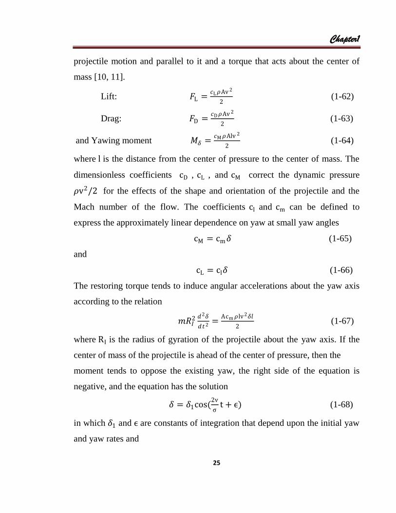
1.2.7 Lift, Drag, and Yawing Moments
A quasi-empirical method of representing the forces recognizes the
dynamic pressure 𝜌v2/2 as the dominant factor in the relation of the forces to
projectile motion. The aerodynamic forces are most conveniently expressed as
lift and drag forces acting at the center of mass in the direction normal to the
𝑭 = 𝒎𝒅𝐯
𝒅𝒕
𝐩 +𝐝𝐩
𝐝𝐬𝐝𝐬
Chapter1
25
projectile motion and parallel to it and a torque that acts about the center of
mass [10, 11].
Lift: 𝐹L =𝑐L𝜌Av 2
2 (1-62)
Drag: 𝐹D =𝑐D 𝜌Av 2
2 (1-63)
and Yawing moment 𝑀𝛿 =𝑐M 𝜌Alv 2
2 (1-64)
where l is the distance from the center of pressure to the center of mass. The
dimensionless coefficients cD , cL , and cM correct the dynamic pressure
𝜌v2/2 for the effects of the shape and orientation of the projectile and the
Mach number of the flow. The coefficients cl and cm can be defined to
express the approximately linear dependence on yaw at small yaw angles
cM = cm𝛿 (1-65)
and
cL = cl𝛿 (1-66)
The restoring torque tends to induce angular accelerations about the yaw axis
according to the relation
𝑚𝑅𝐼2 𝑑2𝛿
𝑑𝑡2=
Acm 𝜌lv 2𝛿𝑙
2 (1-67)
where RI is the radius of gyration of the projectile about the yaw axis. If the
center of mass of the projectile is ahead of the center of pressure, then the
moment tends to oppose the existing yaw, the right side of the equation is
negative, and the equation has the solution
𝛿 = 𝛿1cos(2v
ςt + ϵ) (1-68)
in which 𝛿1 and ϵ are constants of integration that depend upon the initial yaw
and yaw rates and
Chapter1
26
ς = 2π 2m𝑅𝐼
2
𝐴𝜌 lc m (1-69)
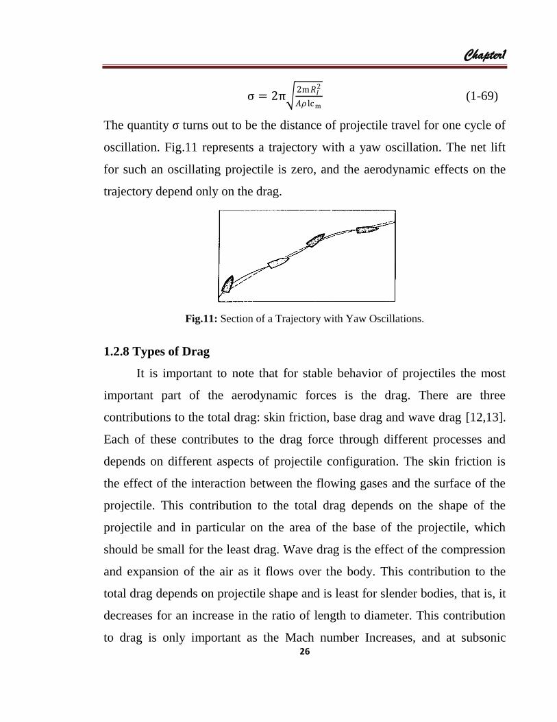
The quantity ς turns out to be the distance of projectile travel for one cycle of
oscillation. Fig.11 represents a trajectory with a yaw oscillation. The net lift
for such an oscillating projectile is zero, and the aerodynamic effects on the
trajectory depend only on the drag.
Fig.11: Section of a Trajectory with Yaw Oscillations.
1.2.8 Types of Drag
It is important to note that for stable behavior of projectiles the most
important part of the aerodynamic forces is the drag. There are three
contributions to the total drag: skin friction, base drag and wave drag [12,13].
Each of these contributes to the drag force through different processes and
depends on different aspects of projectile configuration. The skin friction is
the effect of the interaction between the flowing gases and the surface of the
projectile. This contribution to the total drag depends on the shape of the
projectile and in particular on the area of the base of the projectile, which
should be small for the least drag. Wave drag is the effect of the compression
and expansion of the air as it flows over the body. This contribution to the
total drag depends on projectile shape and is least for slender bodies, that is, it
decreases for an increase in the ratio of length to diameter. This contribution
to drag is only important as the Mach number Increases, and at subsonic

Chapter1
27
speeds it is negligible. Wave drag is defined with reference to the cross-
sectional area.
The total drag coefficient is defined with reference to the cross-
sectional area; hence, it is related to skin friction and base and wave
components as
cD = cDw +cDw As
A+ cDb
Ab
A (1-70)
(wave drag) (skin friction) (base drag)
when As equals the wetted area of the body, Ab equals the effective area of the
base, and A equals the cross-sectional area of the body[fig.12].
Fig. 12: Drag Coefficient as a Function of Mach number Typical
of Common Projectile Shapes[Ref.3].
1.2.9 Velocity
The higher the velocity of the projectile the greater the resistance of the
air will be. For a given increase in muzzle velocity the resulting increase in
range is greater at low muzzle velocities than those that are higher. For muzzle
velocities around the speed of sound (approximately 340 m/s) a small
variation in muzzle velocity causes a disproportionate variation in range. As

Chapter1
28
the projectile travels through the air it is affected by three forces as follows:
(i).Nose Resistance: Nose resistance is a consequence of pressure drag at
subsonic velocities and compressive resistance (wave drag) at supersonic
velocities. Nose resistance increases as velocity increases until the velocity
reaches Mach 1. Nose resistance peaks near Mach 1 due to the development of
supersonic flow and shock waves around the nose [Fig.13]. Suffice to say that
a projectile with a long, slender nose will experience less pressure drag at
subsonic velocities and less compressive resistance at supersonic velocities
than a projectile with a blunt-shaped nose [14].
(ii).Tail/Base Drag: Tail drag arises from pressure in the base region of the
projectile that acts upon the base. Its effect can be very significant. The
stream-line flow around the projectile tends to break away at the base creating
a large cavity and wake. This causes the pressure at the base to be less than
ambient and results in tail drag. As projectile velocity increases towards Mach
1 the pressure at the base tends to zero [15].
Fig.13: Factors Affecting Projectile Velocity [5]
(iii).Skin Friction: A rough surface on the projectile will increase resistance,
thereby decreasing range. Its effect is normally the least of the three sources of

Chapter1
29
resistance but in the case of a long, thin projectile, such as a rocket body, it
can be relatively greater. In general, the effect of skin friction on a projectile is
small. The relationship between these three factors for a conventional
projectile is shown in Fig.13 [16].
1.2.10 Reynold's Number
The resistance encountered by the projectile as it passes through the
atmosphere is directly related to viscosity (the measure of the flow resistance
of the atmosphere gases) and is of particular interest to ballisticians.
Experiments have shown that if the ratio of the inertia forces to viscous forces
was preserved for similar shaped projectiles in different fluids, then the flow
about the projectiles would be identical. This ratio is known as Reynold's
number (Re) and is commonly shown as:
Re =Vκ
μ(1-71)
V = velocity , κ = length of projectile
μ = kinematic viscosity(1.45 × 10⁻⁵ M2/sec at sea level)
If Reynold's number is very large the inertia forces will dominate and if it is
very small, viscous forces will dominate. As the projectile moves through the
air, a velocity gradient forms between the undisturbed gases of the atmosphere
and those immediately adjacent to the projectile. This gradient grows in
thickness from the nose of the projectile; the degree of growth is dependent
upon the state of the boundary layer. Generally, when Reynold's number is
low the flow is orderly and steady (laminar flow). When Reynold's number is
high the flow is orderly but very energetic (turbulent flow) [17].
A Knowledge Reynold's number defines the state of the boundary layer and

Chapter1
30
leads to one of the following:
(i) The effect that protuberance or roughness will have on skin friction;
(ii) The sensitivity of the flow field to body curvature; and
(iii) The extent of the cavity in the base of the projectile.
1.2.11 Effects Due to Velocity
Subsonic Velocities: If the projectile is travelling at less than the
velocity of sound (less than about 340 m/s) the compression at the nose is
transmitted away from the projectile in all directions and the resistance due to
the compression waves is negligible [Fig.14]. Most of the resistance at
velocities well below that of sound waves in air is due to:
(i) the formation of a wake behind the base of the projectile which is known
as tail drag (or base drag); and
(ii) Air sticking to the surface of the projectile, which is known as skin
friction.
For projectiles required to travel at subsonic speed, it is an advantage to
streamline the base in an effort to reduce tail drag [18].
Fig. 14: Compression Waves at Subsonic Velocities
Supersonic Velocity: At velocities above the speed of sound, large
pressure waves are suddenly generated, as from an explosion. These pressure
waves propagate into the atmosphere with an increasing velocity because they

Chapter1
31
are compressing the atmospheric gases, raising their temperature and hence
the local speed of sound.
The compression waves eventually come together and form a conical shock
wave at the nose of the projectile [Fig.15]. With a projectile that has a long
pointed nose, the shock wave forms at the nose, that is, is attached. With a
projectile having a blunt nose, the shock wave forms ahead of the projectile,
the blunter the nose the higher the wave drag and, therefore, the greater the
retardation. The angle of the shock cone decreases with the increase of the
Mach number and at hypersonic speeds (M>5) the shock wave almost follows
the shape of the body. Because the projectile is a finite length body travelling
supersonically, the disturbance generated must also be finite, and so a nose
shock wave is accompanied by a tail shock wave. The tail shock wave appears
to originate from the neck of the wake. This pair of shock waves constitutes
the sonic boom heard from bullets, projectiles or aircraft travelling at
supersonic velocities [19].
Transonic Velocities: The energy to overcome air resistance can only
come from the kinetic energy of the projectile. The projectile loses energy at a
greater rate when travelling supersonically than when travelling subsonically.
At the velocity of sound there is a condition of mixed subsonic and supersonic
motion. In this region, the projectile's behavior is unpredictable because the
air resistance is changing rapidly. This is known as the transonic zone. In this
zone, small changes in the projectile's velocity will cause marked changes in
resistance. Small variations in velocity due to wind, air or charge temperature
may contribute to these changes in resistance; however, this has not been
confirmed.

Chapter1
32
It is important that the projectile is steady when it enters the transonic zone.
Since it is common for the projectile to be unsteady just outside the muzzle of
the gun due to initial yaw, and the turning moment is strongest in the transonic
region, firing of projectiles in the area of the velocity of sound is avoided
when possible. Guns that have velocities in the area of the velocity of sound,
however, have given adequate accuracy. When the projectile is travelling at
the speed of sound, the compression waves and the projectile are travelling at
the same velocity [Fig.16] [20].
Fig. 15: Compression Waves at Supersonic Fig.16: Compression Waves at Transonic
Velocities Velocities
1.2.12 Projectile Design
Diameter: Two projectiles of identical shape but of different size will
not experience the same drag. For example, a larger projectile will offer a
larger area for the air to act upon; hence, its drag will be increased by this
factor. The drag of projectiles of the same shape is proportional to the square
of the diameter.
Base Design: A projectile with a boat-tail base (streamlined)
encounters less drag than one with a cylindrical base, especially at velocities
below the speed of sound. As the air moves over the cylindrical base
projectile, there is no external force to change its direction so the air flow

Chapter1
33
separates at the base and a vacuum forms, Fig.17 (1). A streamlined design
changes the direction of the air flow, thereby reduce the size of the vacuum
Fig.17 (2). A streamlined projectile also offers less base area, which further
reduces base drag. A considerable reduction in the amount of drag can be
achieved by the emission of a jet of gas from the base of the projectile. A
study was made in Sweden on the use of base bleed for increasing the range of
the 105 mm projectile. The results showed that at Mach 2, base drag was
reduced by about 50 percent and range improved by over 20 percent. This
principle is utilized in the Base Bleed option being developed with the
experimental 155 mm Extended Range Full Bore (ERFB) projectile. Drag can
also be reduced by spoilers, deliberately designed into the projectile near or at
the base. These spoilers break up the smooth and orderly (laminar) flow of air
and cause it to be turbulent, as shown in Fig.18. The turbulence tends to fill
the area behind the projectile with air, thereby reducing drag [21].
Nose/Head Design. The shape of the projectile nose is expressed in
terms of Caliber Radius Head (CRH) and is defined in terms of length and
radius of curvature of the ogive, both expressed in calibers. Fig.19 shows a
simple CRH of 2 calibers and a compound CRH with the same length of head
but the curvature is reduced by using a radius of 3 calibers [Ref.3].
Fig.17: Effects of Base Design on Air Flow Fig. 18: Air Turbulence Caused by Spoilers

Chapter1
34
Fig. 19: Caliber Radius Head
The optimum use of the length available for the ogival head [fig.20],
parallel portion and the base depends on the use for which the projectile was
designed. For projectiles that are fired at supersonic velocities, but may travel
at subsonic range, a streamlined base is required. Antiaircraft or anti-tank
projectiles are fired at supersonic velocities and are supersonic throughout
their operational range, hence, a streamlined base is not required and a
cylindrical base is used. A streamlined base is found on projectiles that travel
at subsonic velocities for a significant portion of their flight and is always
used when maximum range is a requirement.
A projectile with a tapered base to overcome tail drag and a long
pointed head to overcome nose resistance would seem ideal. A long thin
projectile, however, does not stand up well to the stresses in the bore and
requires a high rate of spin, or fins, to keep it stable in flight. A tapered base
allows the propellant gases to escape at shot ejection in a way that may cause
instability and is the reason why high velocity projectiles normally have a
cylindrical base. Also, a long head on a projectile of fixed overall length

Chapter1
35
results in the projectile being inadequately supported in the bore (because of
the short walls). This would cause high initial yaw and loss of stability.
Where a projectile has a secondary role, i.e. anti-tank or illuminating, separate
firing tables are provided. The projectile could be designed to match the
primary round but this is not desirable as separate firing tables would still be
required and in some cases, performance would be degraded. Current design
philosophy is to use the same CRH and base design on the complete family of
projectiles [22].
Fig.20: Long Nose ogive of the 6.18 Calibers
1.2.13 Ballistics Coefficient
Because of their physical characteristics, some projectiles are more
effective in penetrating air than others. Those projectiles that perform well in
air can be said to have a better carrying power. If two different projectiles are
projected at the same velocity under the same conditions, the projectile with
the better carrying power will travel further. To illustrate the point, it is
common knowledge that a baseball will travel further than a tennis ball when
thrown in the same direction with the same velocity.
The energy available to overcome the resistance of the air is derived from the
kinetic energy of the projectile, that is, from the mass and velocity of the

Chapter1
36
projectile. For a given velocity and type of atmosphere, the carrying power
must depend on the following physical characteristics of the projectile:
(i) Mass (M). The greater the mass, the greater the energy and the greater the
carrying power.
(ii) Diameter (d). The greater the size of the hole the projectile must bore
through the air, the greater the resistance and the less the carrying power.
The size of the hole varies as d2.
(iii) Shape. This is deduced by Κ . In fact, it has been found impossible to
separate the effect of this factor from a steadiness factor, 𝜍 (sigma). Their
product Κ𝜍 is used as a single factor and is determined by trial firings.
Κ ∗is 1 for the standard shape for which the drag law has been obtained
but any degradation of this shape, for example, by a fuze profile that is less
sharp than the standard, will give a value of a Κ ∗greater than 1. The
greater the value of Κ ∗, the less the carrying power.
In summary, for a given velocity and atmosphere, the carrying power of a
projectile is proportional to its mass M and is inversely proportional to Κ ∗ 𝑑2.
That is to say:
Carrying power =M
Κ∗𝑑2 (1-72)
This ratio is called the Standard Ballistic Coefficient (c𝜍 ):
c𝜍 =M
Κ∗𝑑2
Where c𝜍 is the ballistic coefficient in a standard atmosphere, M is the
projectile weight,d is the projectile diameter,Κ ∗ are two coefficients that
represent shape and degree of stabilization.
The numerical value of c𝜍 depends on the units of measurement. Defined in
this way, c𝜍 is a universal measure of ballistic performance. No matter what

Chapter1
37
the projectiles are, if they have the same value of c𝜍 they will behave
identically in flight in the same atmosphere.
A projectile becomes considerably heavier with only a small increase in
diameter d, since for a given material the weight varies as 𝑑2. Thus a large
projectile will normally have a larger (better) value of c𝜍 than a smaller
projectile. However, if a small projectile is made of dense material so that its
mass M is comparatively large, this projectile may have a c𝜍 as good as, or
better than, the c𝜍 of a larger projectile of normal density. This is an important
consideration in connection with modern composite armour-piercing shot
[23].
1.3 Terminal Ballistics
Terminal ballistics is that part of the science of ballistics that relates to
the interaction between a projectile and target. The target could be a tank,
truck, command post, aircraft, missile, ship, etc., so that the possible
interactions could depend on a myriad of structural details. Fortunately,
terminal ballistics is simplified by the common observation that a projectile
traveling at ordnance velocities produces the hole through which the projectile
passes and extremely localized material failure immediately adjacent to the
hole. The only relevant properties of the target are those along the path of the
projectile and a few projectile diameters to the side. Thus, the overall
interaction of a projectile with a complex target is simplified to the impact of
the projectile with an array of barriers. The way these barriers are
interconnected and supported is not very important. In designing weapons and
ammunition, maximum terminal effect is the desired objective. A proper
balance among many factors is essential to accomplish this purpose. The most

Chapter1
38
important of these factors are; (i) terminal velocity; (ii) shape, weight and
material used in the projectile; (iii) type and weight of explosive charge;
and(iv) fuzing system.
1.3.1 Examples of Targets
A simple example of a target is a building that stores munitions
[24].The building is usually a reinforced concrete structure with soil pushed
up against its walls. The concrete and soil barriers protect the vulnerable
munitions that are stored inside. The thicknesses and obliquities that are
presented to a projectile depend on the trajectory of the projectile. If the
projectile still has velocity after perforating the barriers, it may either cause
mechanical damage or detonate the munitions. A tank is a much more
sophisticated target. Its military value lies in its mobile firepower. Anything
that decreases its mobility or impairs its firepower destroys its military value.
The components of greatest value are the ammunition, engine parts, personnel,
fuel, and the Suns and fire-control system. These are protected by the armor
plate of the turret, sides, and bottom of the vehicle [Fig.21]. The terminal
interaction of a projectile with this target is a series of perforations through
these barriers that impacts against vulnerable components. The weight that a
tank designer can allot to armor is limited by the power of the engine, and
therefore the armor material has to be very tough.
An aircraft is still another target that derives its military value from its
mobility and firepower. The vulnerable components of an aircraft are
comparable to those of the tank. Weight limitations on aircraft prevent the use
of thick protective barriers. In fact, there are few protective barriers as such,

Chapter1
39
but the structural elements to comprise the airframe must also serve as
protective barriers.
Fig.21: Distribution of Armor Thicknesses, Typical World War II Tank.
These and many other examples show that the terminal ballistics of a
projectile can almost always be viewed as one or more interactions with
barriers that serve to deny the projectile access to vulnerable components at
velocities that could destroy the vulnerable components. A barrier succeeds by
(1) simply decelerating the projectile, (2) breaking the projectile into
fragments and decelerating the fragments, or (3) deforming the projectile and
decelerating the projectile in its less efficient shape. It is assumed that the
projectile is properly designed so that the barrier decelerates the projectile but
never succeeds in resisting the projectile with sufficient force to cause it to
shatter or deform. This is actually the assumption of a majority of the theories
of armor penetration. It is at least approximately correct for many real
situations and vastly simplifies analysis.
1.3.2 Examples of Projectiles
Figure 22 shows different types of projectiles and the features of internal
design that are used to make the projectile non-deforming during impact.
25mm
37 mm
50 mm
75 mm

Chapter1
40
(a) Bullets (ball)
(b) Bullets (armor-piercing)
(c) Projectiles
Fig.22: Examples of non-deforming projectiles.
Fig.22 (a) shows the cross sections of .30- and .50-calilber bullets that are
intended to attack lightly protected personnel and equipment. These consist of
a lead alloy or mild steel core and a jacket. These will be non-deforming only
in the attack of light armor and extended barriers that are not very resistant to
penetration. Fig.22 (b) shows bullets of the same calibers that are intended to
attack armor. The cores of these armor-piercing bullets are hard, tough steels
or a material like tungsten carbide. The nose shape of the core is chosen to
attain reasonable performance at obliquities. The jacket includes a windshield
that gives the bullet optimum aerodynamic properties. As long as the core
material has an advantage in hardness over the barrier material, the projectile
will be essentially non-deforming. Fig.22(c) shows larger-caliber projectiles,
one that is solid steel, and one that has a cap on the nose of the core to assist in
armor penetration.
Chapter1
41
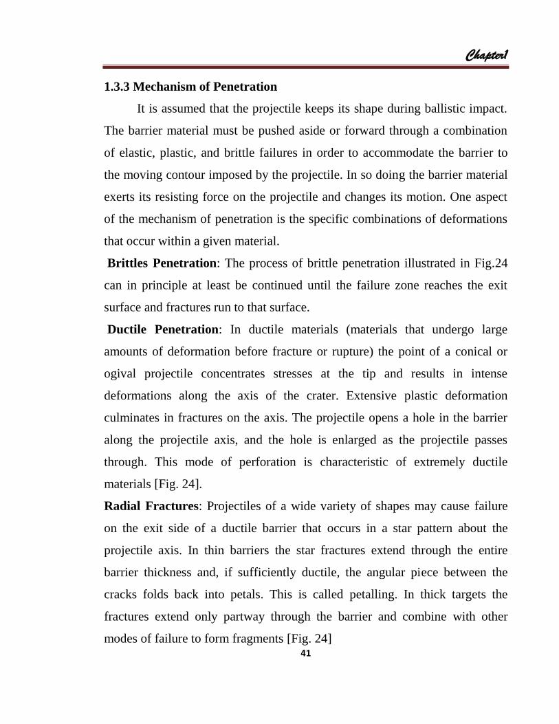
1.3.3 Mechanism of Penetration
It is assumed that the projectile keeps its shape during ballistic impact.
The barrier material must be pushed aside or forward through a combination
of elastic, plastic, and brittle failures in order to accommodate the barrier to
the moving contour imposed by the projectile. In so doing the barrier material
exerts its resisting force on the projectile and changes its motion. One aspect
of the mechanism of penetration is the specific combinations of deformations
that occur within a given material.
Brittles Penetration: The process of brittle penetration illustrated in Fig.24
can in principle at least be continued until the failure zone reaches the exit
surface and fractures run to that surface.
Ductile Penetration: In ductile materials (materials that undergo large
amounts of deformation before fracture or rupture) the point of a conical or
ogival projectile concentrates stresses at the tip and results in intense
deformations along the axis of the crater. Extensive plastic deformation
culminates in fractures on the axis. The projectile opens a hole in the barrier
along the projectile axis, and the hole is enlarged as the projectile passes
through. This mode of perforation is characteristic of extremely ductile
materials [Fig. 24].
Radial Fractures: Projectiles of a wide variety of shapes may cause failure
on the exit side of a ductile barrier that occurs in a star pattern about the
projectile axis. In thin barriers the star fractures extend through the entire
barrier thickness and, if sufficiently ductile, the angular piece between the
cracks folds back into petals. This is called petalling. In thick targets the
fractures extend only partway through the barrier and combine with other
modes of failure to form fragments [Fig. 24]
Chapter1
42
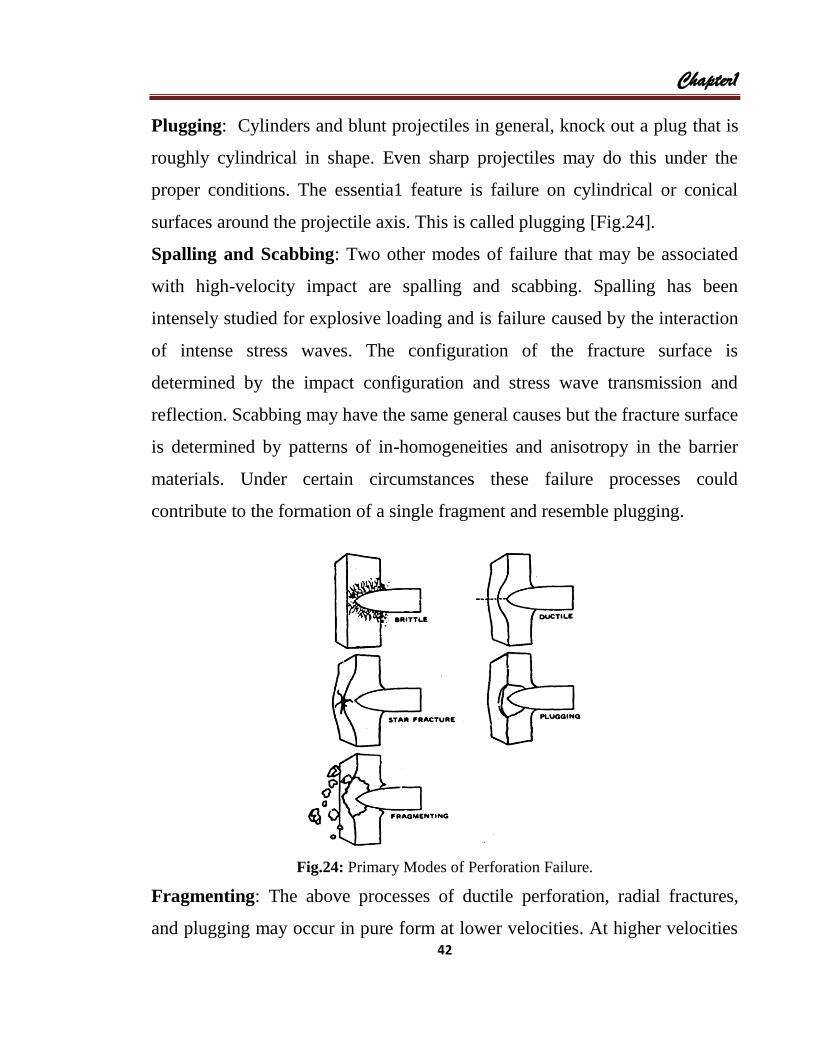
Plugging: Cylinders and blunt projectiles in general, knock out a plug that is
roughly cylindrical in shape. Even sharp projectiles may do this under the
proper conditions. The essentia1 feature is failure on cylindrical or conical
surfaces around the projectile axis. This is called plugging [Fig.24].
Spalling and Scabbing: Two other modes of failure that may be associated
with high-velocity impact are spalling and scabbing. Spalling has been
intensely studied for explosive loading and is failure caused by the interaction
of intense stress waves. The configuration of the fracture surface is
determined by the impact configuration and stress wave transmission and
reflection. Scabbing may have the same general causes but the fracture surface
is determined by patterns of in-homogeneities and anisotropy in the barrier
materials. Under certain circumstances these failure processes could
contribute to the formation of a single fragment and resemble plugging.
Fig.24: Primary Modes of Perforation Failure.
Fragmenting: The above processes of ductile perforation, radial fractures,
and plugging may occur in pure form at lower velocities. At higher velocities
Chapter1
43
these combine with spalling and scabbing or with secondary ductile and brittle
failure processes to produce many fragments [Fig.24].
1.3.4 Application of Conservation Laws
The final results of the interaction of a projectile and a tough barrier are
new rigid body motions of the projectile and barrier, changes of shape for
these bodies, and changes of energy. Conclusions, about the interrelation of
initial and final motions and changes of energy can be reached by applying
conservation of energy and momentum to, the initial and final states with little
or no concern for the details of the intervening events.
Conservation of energy and momentum are first applied to the initial
and final states of rigid body motion (Fig.25 of the projectile/barrier system
with clean perforation of the barrier, i.e., perforations by ductile or petalling
modes. Conservation of momentum requires that
𝑚1𝑣0 = 𝑚1𝑣1 + 𝑚2𝑣2 line-of-flight momentum (1-73)
0 = 𝑚1𝑤1 + 𝑚2𝑤2 off-line-of-flight momentum (1-74)
Conservation of energy requires that
𝑚1𝑣0
2
2=
𝑚1 ( 𝑣12+𝑤1
2)
2+
𝑚2 ( 𝑣22+𝑤2
2)
2+ 𝐸0 (1-75)
where 𝐸0 is the amount of energy that is converted from kinetic to non-kinetic
form. This can occur by many processes, in dissipative processes in elastic
waves or in the permanent deformations of plasticity and fracture, for
example.
The components of off-line-of-flight momentum depend on the deflection
angles Ω and 𝜓 𝑤1 = 𝑣1𝑡𝑎𝑛Ω (1-76)
𝑤2 = 𝑣2𝑡𝑎𝑛𝜓 (1-77)

Chapter1
44
and thus 𝜓 and Ω are interrelated
𝑡𝑎𝑛𝜓 =𝑚1𝑣1
𝑚2𝑣2𝑡𝑎𝑛Ω (1-78)
Since 𝑚2𝑤2 = 𝑚1𝑤1
= 𝑚1𝑣1𝑡𝑎𝑛Ω (1-79)
𝑤2 =𝑚1𝑣1
𝑚2tanΩ (1-80)
Fig.25: Perforation at obliquity With Deflection of the Projectile
Conservation of energy is expressed as
𝑚1𝑣02 = 𝑚1𝑣1
2 + 𝑚2𝑣22𝑡𝑎𝑛2Ω +
𝑚12
𝑚2 𝑣1
2𝑡𝑎𝑛2Ω + 2𝐸0 (1-81)
The equation for momentum and energy conservation can be solved for v1 and
v2;
v1 = (R1v0 ± R2 𝑣0 2 −
2𝐸0
R2m1+ 𝑡𝑎𝑛2Ω (R1 − R2) 𝑣0
2 +2𝐸0
m1R1 )𝑐𝑜𝑠2Ω
(1-82)
v2 =𝑚1𝑣0
𝑚2 1 + R1𝑐𝑜𝑠2Ω ±

Chapter1
45
R1( 𝑣0 2 −
2𝐸0
R2m1+ 𝑡𝑎𝑛2Ω (R1 − R2)v0 +
2𝐸0
m1R1 )𝑐𝑜𝑠2Ω (1-83)
Where R1 =m1
m1+m2 , R2 =
m2
m1+m2
The quantities 𝐸0 and Ω account for the individual properties of the given
impact system, such is the projectile shape, the mechanical properties of the
barrier, and the mode of failure of the barrier. Special cases of the above
equations make it easier to understand the, consequences of the conservation
laws and the role of the parameters 𝐸0 and Ω .
1.3.5 Simple Terminal Ballistics Theories
Several theories of the interaction between a projectile and barrier at
zero obliquity calculate measures of the defeat of a projectile in tractable form
by using simple assumptions about the response of the barrier to impact [26].
These all result in calculations of the energy E0 that is changed from kinetic to
non-kinetic form. The earlier theories calculate the work done in penetration
using specific assumptions on the nature of the contact forces resisting
penetration. More recent theories explicit determine the changes in energy that
occur as penetration proceeds. In addition, assumptions are made often
implicitly on the motion of entry and exit boundaries and on the failure
process that terminates resistance or initiates changes in the form of
resistance.
Penetration resistance has been estimated by simple expressions that use
empirical constants for each barrier of interest. The Euler-Robinson form is
𝐹𝑅 = 𝑐1𝐴 (1-84)

Chapter1
46
where 𝐴 is the cross-sectional area of the projectile at the current stage of
embedment, and 𝑐1 is a constant for the particular projectile and barrier. This
is equivalent to assuming that the barrier material has been loaded until it has
reached a limit 𝜍𝑌 beyond which it cannot go. The constant 𝑐1 is then the yield
limit 𝜍𝑌 .
A slightly more complicated form for the penetration resistance is the Poncelet
form that was introduced in the discussion of soil penetration
𝐹𝑅 = (𝑐1 + 𝑐3𝑣2)𝐴 (1-85)
where 𝑐1 and 𝑐3 are empirical constants. This can be interpreted as an
extension of the Euler-Robinson form by consideration of inertial effects
through an adaptation of the methods of exterior ballistics. Thus the Euler-
Robinson form of penetration resistance can be combined with the assumption
that the entry and exit surfaces have negligible motion, and that the mode of
perforation is ductile (the barrier material opens at the tip of the projectile and
expands about it). The force on the projectile at any penetration is 𝐹𝑅 = 𝑘𝐴
and the energy 𝐸0 that is dissipated in the penetration is 𝐸0 = 𝑘𝐴𝑑𝑝 = 𝑘𝜏𝑃
0,
where 𝑘 shape factor and 𝜏 is the volume of the indentation in the barrier.
For non-deforming projectiles the crater volumes are easily estimated
from the nose shape and penetration, 𝜏 = 𝐴(𝑝)𝑑𝑝𝑃
0 where 𝐴(𝑝) is the cross-
sectional area of the projectile as a function of penetration. Examples of 𝐴(𝑝)
are
Spherical nose 𝐴 𝑝 = 𝜋(𝑑𝑝 − 𝑝2) (1-86)
Conical nose (cone angle a) 𝐴 𝑝 = 𝜋𝑡𝑎𝑛2(𝑑/2)𝑝2 (1-87)
Flat-ended nose (and penetration 𝐴 𝑝 = 𝜋𝑑2/4 (1-88)
beyond complete nose embedding)

Chapter1Chapter1Chapter1Chapter1
47
An example of the application of these results to penetration data is shown in
Fig.26. The data are penetrations of conically ended steel projectiles into brass
targets. The targets were plates 9 inches on a side and 1/4 inch thick. The
0.875-inch-long projectiles were 1/4 inch in diameter with a cone angle of 90
degrees. The values of the mass ratios R� and R� are 0.002 and 0.009,
respectively, so that special case 3 is appropriate. The penetration of the
projectile up to the shaft is given by
���
� = k �� �(/2)������ = k ���
� (1-89)
or � = ��������
� (1-90)
Fig. 26: Penetration Data for a Conical Ended Projectile [3].
and beyond the nose
���
� = k�� + �!�" (p − ��) (1-91)
Region of in-deformation
of the conical nose
%& = '(
& + )*(+) − +()),-.)&
%/& = /+)/0

Chapter1
48
or p = 𝑝0 +2𝑚(𝑣2−𝑣0
2)
𝐾𝜋𝑑2 (1-92)
where 𝜏0 is the volume of the nose and 𝑝0 is the length of the nose. The
constant k was chosen to fit the data [fig.26].
1.3.6 Anti-Tank Projectile
There are two main types of anti-tank projectiles which, by virtue of
their action, can be classified as either shot or shell.
Shot. Shot defeats armour by means of kinetic energy imparted by velocity
and weight. As shot is fired at high velocity it is necessary that it has a
good ballistic shape so that in flight loss of velocity is kept to a minimum.
The use of high velocities is a user advantage in that corrections for
moving targets are normally small.
Shell. HEAT and HEP, defeat armour by virtue of the action of their
explosive content. The highest possible velocities are required in order to
improve the chance of a hit with both kinetic energy (KE) and chemical
energy (CE) projectiles. The performance against armour of both HEAT
and HEP projectiles is independent of range [5].
1.3.7 The behavior of materials under impact and explosive loading
The properties of a given material are described by the relation between
the stresses and strains within the material, that is between the internal forces
per unit area and the relative elongations or contractions and shearing of the
material. The elongation of a rod in a simple testing machine is an example.
The machine applies a pulling force on the rod, and allows measurement of
the elongation of the rod along its axis and the amount of contraction of the

Chapter1
49
rod in cross-sectional area. From these data we have the following stresses and
strains;
A tensile stress 𝜎1 = 𝐹/𝐴 (1-93)
A tensile strain (from the extension along the axis) 𝜖1 = ∆𝑙/𝑙 (1-94)
A compressive strain (from the contraction perpendicular to the axis of the
rod) 𝜖1 = ∆𝑙/𝑙 (1-95)
A test is usually carried out to the point of final failure of the rod. If the stress
and strain data are plotted directly using the initial cross-sectional area A0 in
the computation of stress, and ∆𝑙/𝑙0 for the strain, the curve representing the
data looks like the curve of Fig.27, and is called an engineering stress/strain
curve.
Fig.27: Engineering Stress/Strain Data [3]
1.4 Glossaries Related to Ballistics
Target: The target is a specified point at which fire is directed.
Point of Impact: The point of impact is the point where the projectile first
strikes an object.
Point of Burst: The point of burst is the point at which a projectile actually
bursts. It may occur before, at, or beyond the point of impact.

Chapter1
50
Inclination of the Trajectory: The inclination of the trajectory is the acute
angle measured from the horizontal plane passing through a given point on
the trajectory to the oriented tangent to the trajectory at this point.
Angle of fall: The angle of fall is the inclination of the trajectory at the level
point, the sign being positive.
Line of Impact: The line of impact is a line tangent to the trajectory at the
point of impact or burst.
Angle of Impact: The angle of impact is the acute angle, at the point of
impact, between the line of impact and a plane tangent to the surface struck.
This term should not be confused with the term angle of fall. They are the
same only when the point of impact is at the level point.
Angle of Incidence: The angle of incidence is the acute angle between the
normal to the surface struck and the line of impact.
Guns and Howitzers: There are no sharp distinguishing features between
guns and howitzers. Generally, guns produce higher muzzle velocities, fire
low angle and have fewer charges than howitzers that fire at both high and
low angles. Although certain differences may be noted, both have the
following properties:
(i)They give projectiles specified initial velocity and direction of motion.
(ii)There is a rapid burning of a propellant charge in a chamber that produces
gas under pressure which forces the projectile to move along the barrel.
Mortars: Mortars are usually small, light and easily handled equipments that
propel projectiles at high angles of elevation. They are usually loaded through
the muzzle whereas guns and howitzers are loaded through the breech.
Mortars usually have smooth bores, but can have rifled bores.

Chapter1
51
Rockets: Rockets are weapons consisting essentially of a warhead and a tube
filled with propellant. Rockets depend for flight on the reaction set up by a jet
of rapidly expanding gases released by the propellant.
Recoilless Guns: Recoilless guns reduce or eliminate recoil forces on the
carriage by creating an opposing force that is normally achieved by venting a
portion of the propellant gases. Lighter carriages can thus be used.
Rifling: Rifling is the set of twisted grooves cut along the interior of the bore,
leaving raised ribs or lands between them.
Caliber: This is the (standard) diameter of the bore, excluding the depth of
the rifling grooves. It is measured from land to land.
Weapon: The term weapon refers to the trunnions, the axis about which the
barrel rotates during elevation or depression and which is at right angles to the
weapon axis.
Weapon Axis: The weapon axis is the axis of the bore taken at the breech and
it is a straight line. This axis will not go through the weapon if the trunnions
are offset from the centre line of the bore.
Axis of the Bore: The axis of the bore is the line passing along the centre of
the barrel .This may, owing to drop, be slightly curved. In this manual, the
axis of the bore will be assumed to be a straight line from the weapon axis to
the muzzle axis.
Muzzle Axis: The muzzle axis is the axis taken at the bore and it is a straight
line.
Droop: Droop is the vertical angle between the axis at the breech and the
muzzle axis. Droop varies with barrel length and/or temperature.
The Breech Clinometers Plate: This is an accurately machined plane surface

Chapter1
52
on top of the breech ring parallel to the weapon axis. Most angular
measurements and adjustments made on the gun are based on this plane.
Muzzle Brake: Muzzle brakes reduce the recoil forces by deflecting a portion
of the propellant gases rearward at the muzzle, thus creating an opposing
force. They are used to increase the stability of the carriage on firing.
Muzzle Velocity: muzzle velocity is the velocity of the projectile at the
muzzle.
The Gun: A gun is a weapon that ejects its projectile by the action of a
burning propelling charge. In a closed chamber a propellant charge burns
more vigorously under pressure .The gun provides the chamber in which the
charge burns.
Projectile: A projectile is an elongated object, such as a bullet, that is
propelled from a gun by a rapidly burning, low explosive propelling charge. It
is fitted with a soft metal rotating (driving) band or bands near its base which
is designed:
(i) To engage with the rifling of the barrel causing spin to be imparted to the
projectile as it moves along the bore;
(ii) To prevent the escape of gases forward past the projectile;
(iii) To offer a certain initial resistance to movement that has the effect of
allowing an initial pressure rise which contributes to the regularity of
burning of the propellant charge and hence regularity in muzzle velocity;
(iv) To assist in centering the projectile in the bore. This is particularly
evident when two driving bands are fitted, one well forward of the other;
(v) For equipments using separate loading ammunition, to hold the projectile
in position when rammed, and to prevent slip-back when the gun is
elevated.
Chapter1
53
Propellant Charge: This is a rapidly burning composition of low explosive
that is burned in a gun to propel the projectile. When suitably ignited, the
propellant charge has an extremely rapid rate of burning, producing many
times its own volume of gases at a high temperature and pressure. No outside
agent, for example oxygen, is necessary for its burning. The rate at which the
contained propellant burns increases with, and is approximately proportional
to, the pressure developed. The higher the pressure, the faster the rate of
burning ; the lower the pressure, the slower the rate of burning.
The total effect of all interior ballistic factors determines the muzzle velocity,
which is expressed in meter per second (m/s) or feet per second (ft/s).
More literature on Ballistics can be found in Refs. [26-33].