chapter one - philadelphia university · chapter one laith batarseh introduction to theory of...
TRANSCRIPT

10/29/2017
1
Chapter One
Laith Batarseh
Introduction to theory of machinery
Introduction to theory of machinery
machine
Machine is a collection of links connected by kinematic pairs to perform a specific task with unique relationship between inputs and outputs
link
A link is usually a rigid body with specific geometry defined by the location of
its kinematic pairs and type
kinematic pairs
It is the connection between two different links that allows a specific type or
form of relative motion between the two links
10/29/2017
2
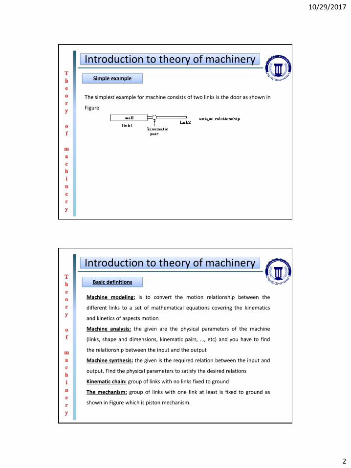
Introduction to theory of machinery
Simple example
The simplest example for machine consists of two links is the door as shown in
Figure
Introduction to theory of machinery
Basic definitions
Machine modeling: Is to convert the motion relationship between the
different links to a set of mathematical equations covering the kinematics
and kinetics of aspects motion
Machine analysis: the given are the physical parameters of the machine
(links, shape and dimensions, kinematic pairs, …, etc) and you have to find
the relationship between the input and the output
Machine synthesis: the given is the required relation between the input and
output. Find the physical parameters to satisfy the desired relations
Kinematic chain: group of links with no links fixed to ground
The mechanism: group of links with one link at least is fixed to ground as
shown in Figure which is piston mechanism.

10/29/2017
3
Introduction to theory of machinery
Examples of mechanisms
Gears
Introduction to theory of machinery
Examples of mechanisms
Gears

10/29/2017
4
Introduction to theory of machinery
Examples of mechanisms
Cams
Introduction to theory of machinery
Examples of mechanisms
Slider crank mechanism

10/29/2017
5
Introduction to theory of machinery
Examples of mechanisms
4-bar mechanism
Introduction to theory of machinery
Examples of mechanisms
Scotch Yoke mechanism

10/29/2017
6
Introduction to theory of machinery
DEGREE OF FREEDOM (DOF):
Degree of freedom is the number of independent relative motion allowed by
the pair. We can classified to:
1. Single DOF mechanisms such as: single rotational motion, single translation
motion and dependent rotation and translation single motion as shown in Figure
2. Two DOF mechanisms such as: rotation such slotted sphere, two translation
motion, one rotation + one translation independently such cam.
Introduction to theory of machinery
DEGREE OF FREEDOM (DOF):
10/29/2017
7
Introduction to theory of machinery
MOBILITY ANALYSIS
Mobility means how much degree of freedom the mechanism has
You must follow these steps to find the mobility (M):
1. One link must be grounded
2. For planer mechanism (i.e. all links move in parallel planes) each link has 3-DOF
(2- translation + 1-revelution)
3. The kinetic pairs restricts the relative motion between bodies as following :
•1DOF pairs restricts two DOF of one body
•2DOF pairs restricts one DOF of one body
4. The remaining degrees of freedom equals to the number of input.
Introduction to theory of machinery
MOBILITY ANALYSIS
The mobility is now calculated as:
21213 PPNM
Where:N is the number of links P1 is the number of pairs that has 1 DOFP2 is the number of pairs that has 2 DOF

10/29/2017
8
Introduction to theory of machinery
MOBILITY EXAMPLES
N = 2
P1 = 1(Rev).
P2 =0 112123 M
Which is Ө
N = 3
P1 = 2(Rev+Tran).
P2 =0
222133 M
Which are Ө and s
Introduction to theory of machinery
MOBILITY EXAMPLES
N = 3P1 = 3.P2 =0
System will not move
N = 4P1 = 4.P2 =0
Which is s
032133 M
142143 M

10/29/2017
9
Introduction to theory of machinery
MOBILITY EXAMPLES
N = 4P1 = 4.P2 =0 Which is Ө2
N = 3P1 = 2.P2 =1
142143 M
1122133 M
Introduction to theory of machinery
MOBILITY EXAMPLES
N=6
P1=7
172163 M

10/29/2017
10
Introduction to theory of machinery
MOBILITY EXAMPLES
N=8
P1=10
1102183 M
Introduction to theory of machinery
MOBILITY EXERCISES
10/29/2017
11
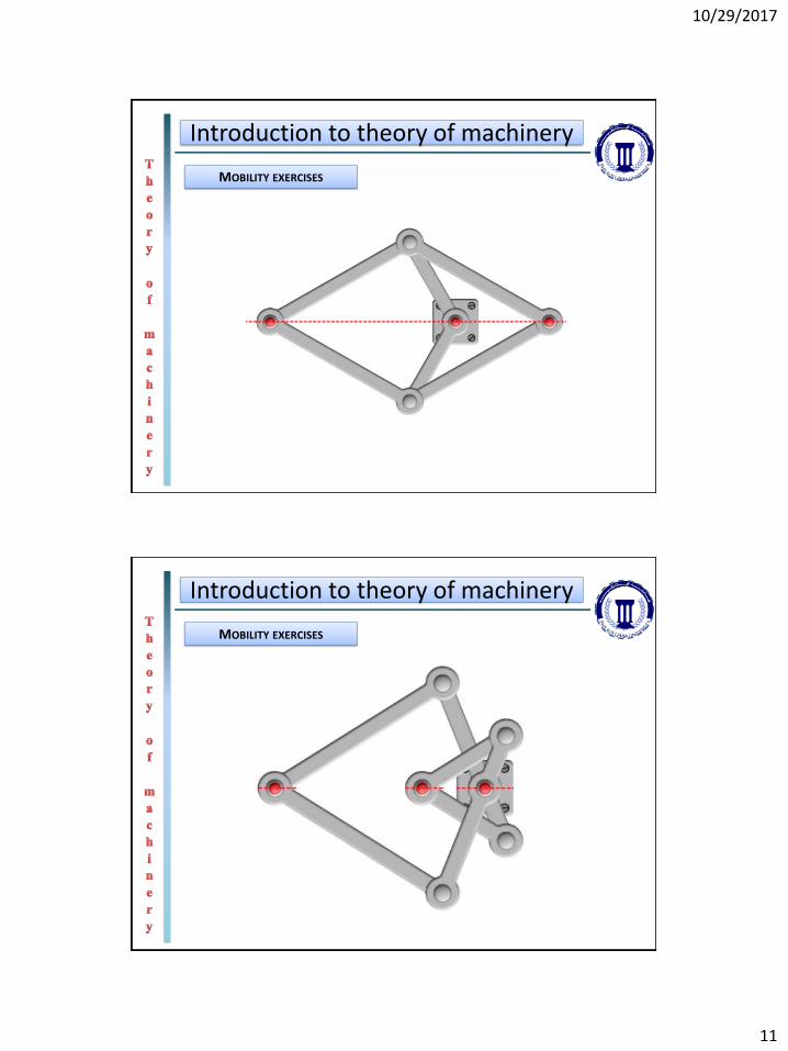
Introduction to theory of machinery
MOBILITY EXERCISES
Introduction to theory of machinery
MOBILITY EXERCISES

10/29/2017
12
Introduction to theory of machinery
MOBILITY EXERCISES
Introduction to theory of machinery
MOBILITY SPECIAL CASES
In some special cases, the mobility calculations results with zero but the system
will be able to move. In such cases, we add one to the mobility ( i.e. M=1). The
figure below illustrates two examples where the system has M=0 and it will
move.

10/29/2017
13
Introduction to theory of machinery
Motor is Link 2
Link 3
Fixed to ground
Link 5
Link 6 Link 7: the slider inside
Joint to ground
No slip
Two joints: revolute + slider
Revolute joint
N=7
P1=9
092173 M
This mechanism is called gear-drive-type window
regulator and it is used to move a car window and so
we add 1 to its mobility
MOBILITY SPECIAL CASES
Link 4