chapter title - techtargetmedia.techtarget.com/search400/downloads/exploring_iseries.pdf ·...
TRANSCRIPT


Chapter title 1
Untitled-2 10/1/2002, 9:23 AM1

Table of Contents vii
vii
Table of Contents
Introduction ........................................................................................... xixWhat This Book Is .......................................................................... xixWhat This Book Is Not .................................................................... xxHow to Use This Book .................................................................... xxYour “Members Only” Web Site .................................................. xxivA Glance Backward ....................................................................... xxvHow These Computers Are Different ........................................... xxix
Chapter 1:What Is an iSeries or AS/400 System? 1
Application-Centric Computing......................................................... 3Open Systems Computing ......................................................... 5Client/Server Computing Systems .............................................. 6Distributed Computing Systems ................................................ 7
Advanced Application Architecture ................................................... 8Why RISC? .............................................................................. 11RISC PowerPC AS Microprocessors ........................................ 12
The A10 Microprocessor ................................................. 14The A50 Microprocessor ................................................. 15The Pulsar Microprocessor .............................................. 16The IStar Microprocessor ................................................ 17
Meet the Family ............................................................................... 17System Unit Members .............................................................. 20
AS/400e Server Model 250 Specifics ................................ 20iSeries 400 Model 270 Specifics ....................................... 22iSeries 400 Model 820 Specifics ....................................... 26iSeries 400 Model 830 Specifics ....................................... 32iSeries 400 Model 840 Specifics ....................................... 36
Server Preload Packages .......................................................... 38SSA—BPCS Client/Server or Mixed Mode ....................... 41MAPICS—MAPICS XA ................................................... 41JBA International—JBA System 21 .................................. 41
rd-toc.pmd 10/1/2002, 12:24 PM7

viii Exploring IBM ~ iSeries and AS/400e Computers
International Business Systems—IBS–ASW ...................... 41Intentia—The Movex System ........................................... 42Baan—BaanERP .............................................................. 42Infinium—Infinium Suite for IBM AS/400 ....................... 42Acacia Technologies—Acacia Suite for AS/400 ................ 43Lilly Software Associates—Visual Manufacturing ........... 43SAP-Base R/3 Package ..................................................... 43SAP—Ready to Run R/3 .................................................. 43
Custom Application Servers ..................................................... 44iSeries 400 Custom Application Server Model SB2 .......... 44iSeries 400 Custom Application Server Model SB3 .......... 47
iSeries 400 Dedicated Servers for Domino ............................... 50Dedicated Server for Domino Model 170D ..................... 50iSeries 400 Dedicated Server for Domino Model 270D ... 51iSeries 400 Dedicated Server for Domino Model 820D ... 51
System Availability........................................................................... 54OS/400 Subsystems and Logical Partitioning .......................... 56
Product Preview—LPAR Enhancements .......................... 59Multisystem Coupling .............................................................. 59Data Resiliency and Application Resiliency ............................. 59Continuous Availability Clustering .......................................... 60Disaster Tolerance ................................................................... 62Upgrades ................................................................................. 62
Upgrading within a Model ............................................... 62Upgrading through a System Unit Swap .......................... 63Upgrading through Migration Towers ............................. 63Upgrades between Models ............................................... 63
Performance Overview .................................................................... 65Benchmark Testing Overview .................................................. 66
8XX Model Priorities ...................................................... 68CPW Benchmark Test Results .......................................... 69Symmetrical Multi-Processing (SMP) ............................... 70Server Performance .......................................................... 70Interactive Performance ................................................... 72Dedicated Server for Domino Benchmarks ...................... 72
OptiConnect Performance ............................................................... 73A Closer Look ................................................................................. 74Hardware Architecture Overview .................................................... 74
Clustering Technology ............................................................. 78What Is OptiConnect/400? .............................................. 78
rd-toc.pmd 10/1/2002, 12:24 PM8

Table of Contents ix
OptiConnect/400–Enabled Functions .............................. 80OptiConnect/400 Environment ........................................ 82
Main Storage ........................................................................... 82Storage Management ............................................................... 83
Virtual Storage ................................................................. 86Auxiliary Storage ..................................................................... 87
Diskette Storage ............................................................... 87Disk Storage ..................................................................... 88Optical Libraries .............................................................. 90Tape Storage .................................................................... 90
Packaging Technology ............................................................. 91Fiber Optic Bus ....................................................................... 92
Chapter 2:Options and Peripherals 93
Workstations ................................................................................... 94InfoWindow II Workstations................................................... 95Operations Console ................................................................. 95Personal Computer (PC) Terminal Emulation ......................... 96Retail Workstations ................................................................. 98IBM Network Station #8361 ................................................... 98
Printing Technology ....................................................................... 101Printers .................................................................................. 104
Impact Printers ............................................................... 105Nonimpact Printers ........................................................ 106
Combined-Function I/O Processor ........................................ 110#2843 PCI IOP .............................................................. 116
PCI Integrated NetFinity Servers (#2865) .................. 117Product Preview......................................................... 118Statement of Direction ............................................... 119Integrated xSeries Server for iSeries ........................... 119Product Preview—NetFinity Server ........................... 120
Workstation Adapters ............................................................ 120#4746 PCI Node Twinaxial Workstation Adapter ......... 120LAN-Connected Terminals ............................................ 121
Main Storage Expansion Options .................................................. 121Model 250 Main Storage Capacities ...................................... 122Model 270 Main Storage Expansion Options ........................ 122Model 820 Main Storage Expansion Options ........................ 123
rd-toc.pmd 10/1/2002, 12:24 PM9
x Exploring IBM ~ iSeries and AS/400e Computers
Model 830 Main Storage Expansion Options ........................ 124Model 840 Main Storage Expansion ...................................... 124Auxiliary Storage Options ..................................................... 125Disk Storage Overview .......................................................... 126
Model 2100 Versatile Storage DataServer ...................... 129Disk Adapters ................................................................ 130
Tape Storage .......................................................................... 131Internal Tape Units ........................................................ 132
2.5 GB ¼-Inch Cartridge Tape Unit .......................... 1324 GB ¼-Inch Cartridge Tape Unit (#6382) ................ 13213 GB ¼-Inch Cartridge Tape Unit ........................... 1337 GB 8 mm Cartridge Tape Unit ............................... 133
External Tape Units ....................................................... 133Tape Libraries ................................................................ 135
Optical Storage Overview ..................................................... 135The #3995 Optical Library ............................................ 136
CD-ROM .............................................................................. 137Auxiliary Storage Controllers ................................................ 138Communications Options ...................................................... 138Local Area Networks............................................................. 139
Ethernet ......................................................................... 141Token-Ring Local Area Networks ................................. 142Integrated PC Server ...................................................... 144Asynchronous Transfer Mode ........................................ 147
Wide Area Networks ............................................................. 147ISDN Basic Rate Interface Adapter ................................ 148The Async Protocol ........................................................ 148The Bisync Protocol ....................................................... 149The SDLC Protocol ........................................................ 150The X.25 Protocol ......................................................... 150The IDLC Protocol ........................................................ 150Frame Relay ................................................................... 151Integrated Fax Adapters ................................................. 151Modems ......................................................................... 151
Integrated Analog Modem #2761 .............................. 152Remote Workstation Controllers and Lines ................... 153
#5394 Remote Workstation Controller ..................... 154 #5494 Remote Workstation Controller ..................... 155
Power and Packaging Options .............................................. 155UPS for Models 250, 270, and 820 ................................ 155
rd-toc.pmd 10/1/2002, 12:24 PM10
Table of Contents xi
Packaging Expansion Features .............................................. 156#7102 Model 250 System Unit Expansion ..................... 156PCI Expansion Tower (#5075) ....................................... 156PCI Expansion Tower #5074/#9074 .............................. 156Migration Tower I (#5033/#5034) ................................. 157Migration Tower I (#5035) ............................................ 157Migration Tower II (#5077) ........................................... 1571.8M I/O Tower #5079 .................................................. 158System Unit Expansion #7104 ....................................... 158iSeries Rack Mount capabilities ..................................... 159
Other Adapter Options .................................................................. 159Cryptographic Processors ...................................................... 159Cryptographic Processors ...................................................... 159
PCI Cryptographic IOA (#4801) .................................... 160
Chapter 3:iSeries and AS/400 Software 161
Software Architecture Overview .................................................... 161System-Licensed Internal Code .............................................. 165How the Software Layers Are Different ................................ 166How the Layers Work Together............................................. 168
Software Compatibility .................................................................. 170Will S/3X Programs Work?.................................................... 170Inside Compatibility .............................................................. 171Applications Architecture ...................................................... 172
Program Portability........................................................ 172Extreme Support Personalized ....................................... 172
EZ Setup .................................................................... 173Internet Setup Wizard ................................................ 174Welcome Center ......................................................... 174
Program Interaction ....................................................... 175Standard User Interface .................................................. 175
Application Programs .................................................................... 175Can Prewritten Programs Fit the Bill? ................................... 176Cross-industry Application Programs .................................... 177
AFP PrintSuite ................................................................ 178Advanced Print Utility ............................................... 178Page Printer Formatting Aid ...................................... 179AFP Toolbox.............................................................. 179
rd-toc.pmd 10/1/2002, 12:24 PM11

xii Exploring IBM ~ iSeries and AS/400e Computers
SAP R/3 AFP Print ..................................................... 179AnyMail/400 and POP3 ................................................. 179Query/400 ...................................................................... 180Encoded Vector Indexing ............................................... 182AS/400 Business Graphics Utility ................................... 184ImagePlus/400................................................................ 185Facsimile Support/400 ................................................... 188CallPath/400 .................................................................. 189Multimedia .................................................................... 190
Client Access Ultimedia Tools for AS/400.................. 191Ultimedia Business Conferencing for AS/400 ............. 192
Job Scheduler for AS/400 ............................................... 194Data Warehousing ......................................................... 197Data Mining .................................................................. 200
Performance ............................................................... 201Capacity ..................................................................... 201Scalability .................................................................. 202Open Interfaces ......................................................... 202Multiple Data Structures ............................................ 202Data-Mining Example ............................................... 203
Collaborative Computing (Lotus Notes/Domino) .......... 203Lotus Notes ............................................................... 207Lotus Enterprise Integrator (NotesPump) ................. 209
Portable Application Solution Environment ................... 210Client Series and Application Development Programs ........... 211Industry-Specific Application Programs................................. 211
Custom Application Programs ....................................... 214
Chapter 4:Operating Systems 216
Operating System Products ............................................................ 217Introduction to Operating System Concepts .......................... 217
Batch versus Interactive Processing ................................ 218What Are Multiuser and Multiapplication
Computer Systems? .................................................... 219OS/400 in the Client/Server Environment? ............................ 220
OS/400—An Executive Overview .................................................. 221A Closer Look at OS/400 .............................................................. 223
Integrated File System ............................................................ 224
rd-toc.pmd 10/1/2002, 12:24 PM12
Table of Contents xiii
Stream Files .................................................................... 226Integrated File System Support ....................................... 227DB2 Query Manager and SQL Development Kit ........... 229SQL Development Kit .................................................... 230Network File System ...................................................... 230Remote File System ........................................................ 231
Client for Windows NT File System........................... 232 Advanced Function Printing ................................................. 232
INTELLIGENT PRINTER DATA STREAM (IPDS) ...... 233DB2 Universal DataBase (UDB) for AS/400 ......................... 233
Universal DataBase Characteristics ................................ 237Complex Object Support ........................................... 238DataLink Data Types ................................................ 238User-Defined Types .................................................... 238User-Defined Functions ............................................. 238
Built-in Database ........................................................... 239Telephone Book ......................................................... 240Physical and Logical Files .......................................... 241Concurrency and Lock Management ......................... 243
Distributed Data Management ....................................... 246DB2 UDB for OS/400—An Overview .................................. 246DB2 UDB for OS/400 ........................................................... 247
Data Propagator Relational Capture and Apply ............ 248Open DataBase Connection ........................................... 248Java DataBase Connection ............................................. 249Data Striping.................................................................. 249Partitioned Database ...................................................... 250Database Monitor .......................................................... 250Database Management .................................................. 251DCE Base Services/400 .................................................. 252CICS Translation Server for AS/400 (5769-DFH) .......... 255
Communications Support ...................................................... 256TCP/IP ........................................................................... 258
Virtual Private Networks ........................................... 260Systems Network Management ...................................... 261
Systems Network Management Example ................... 262Systems Network Architecture ....................................... 263Wireless Local Area Network ........................................ 264S/390 Communications Support .................................... 264
Client Access .......................................................................... 265
rd-toc.pmd 10/1/2002, 12:24 PM13

xiv Exploring IBM ~ iSeries and AS/400e Computers
AS/400 Client Access Family for Windows .................... 266AS/400 Client Access Family .......................................... 274AS/400 Client Access Express for Windows ................... 275
Lotus Notes 5.0 Client Support ................................. 277SystemView............................................................................ 278
Commitment Control and Journaling ............................ 281Backup/Recovery ........................................................... 282
Operations Navigator ................................................ 283EDMSuite OnDemand for AS/400 ............................ 284Backup Recovery and Media Services/400 ................. 286Adstar Distributed Storage Manager.......................... 288System Managed Access Path Protection ................... 290Hierarchical Storage Management ............................. 291Utility-Failure Recovery ............................................. 291Disk Failure Recovery ................................................ 292
System Manager/400...................................................... 293Management Central ..................................................... 294
Management Central Methodology ............................ 295AS/400 Performance Tools ............................................. 296Managed System Services for AS/400 ............................ 297
NetFinity for AS/400.................................................. 297Application Development Facilities ....................................... 298
Application Development ToolSet/400 ........................... 301Application Development Tools—Printing ..................... 302Application Development Tools—Program Group 1...... 304 Application Development Tools—Program Group 2 .... 305Application Development Tools—
Debug and Maintenance ............................................ 306Application Development Tools—Programming ............ 307Application Development Tools—Other Methodologies 307Integrated Language Environment (ILE) ........................ 309Websphere Studio for AS/400 ........................................ 310
AS/400 Kernel Threads .......................................................... 311Emerging Application Development Environments ........ 313
Client/Server Computing Model ................................. 315Object Technology ..................................................... 317
Emerging Applications Environments ............................ 322Frameworks ............................................................... 323OpenDoc ................................................................... 326ORB Support ............................................................. 326
rd-toc.pmd 10/1/2002, 12:24 PM14

Table of Contents xv
Java ............................................................................ 326Enterprise Java Beans ..................................................... 333
Using Java at the Client ............................................. 334Product Preview - Linux ............................................ 334Product Preview - Altered Program Objects .............. 334
System/3X Compatibility ....................................................... 335Software Solution Packages ................................................... 336
AS/400e Server 150 BasePak .......................................... 336
Chapter 5:AS/400 and Communications—An Introduction 342
Computer Communications in the Office—An Introduction ......... 342What Is SNA? ................................................................................ 343IBM Electronic Customer Support Communications ..................... 344Remote Workstations .................................................................... 347Distributed Computer Communications ........................................ 349
Distributed Networks ............................................................ 351Distributed AS/400 Network Example .......................... 351
APPC/APPN .......................................................................... 354Filter Lists ...................................................................... 355
System Clustering .................................................................. 355ObjectConnect/400................................................................ 357
IBM’s Overall Networking Blueprint ............................................. 357Applications Layer ................................................................. 358Application Support Layer .................................................... 359
Multi-Vendor Application Program Interfaces ............... 361The CPI-C Interface................................................... 361The Remote Procedure Call ....................................... 361The Messaging and Queuing Interface ....................... 362
Transport Network Layer: SNA-TCP/IP-MPTN-APPN........ 363Multiprotocol Transport Networking ............................ 364Advanced Peer-to-Peer Networking ............................... 365
Subnetworking Layer............................................................. 365Intranet .................................................................................. 366Retail Terminals ..................................................................... 367
Intranet/Internet Security ............................................................... 368Internet Connection Secure Server ......................................... 368Cryptographic Access Provider .............................................. 373
Hardware Cryptography ................................................ 374
rd-toc.pmd 10/1/2002, 12:24 PM15
xvi Exploring IBM ~ iSeries and AS/400e Computers
HTTP Server for AS/400 ................................................ 375SET Internet Security Manager ...................................... 375
Digital Certificate Manager ....................................... 376Security Wizard ..................................................................... 377
Firewalls ........................................................................ 377AS/400 and the Internet ......................................................... 378
Electronic Business ......................................................... 381IBM WebSphere Application Server for AS/400 ............. 381
WebSphere Standard Edition V3.5 for AS/400 .......... 382WebSphere Application Server
Advanced Edition V3.5 for AS/400 ........................ 382WebSphere Host Integration ...................................... 383
Net.Data ........................................................................ 383NetQuestion .................................................................. 384WebSphere Commerce Suite .......................................... 385Domino 5.0 for AS/400 ................................................. 386
Domino-Licensed Program Server Choices ................ 390Domino Licensed Program Client Choices ................ 391
Domino.Merchant ......................................................... 392WebSphere Commerce Suite vs. Domino.Merchant ....... 392OS/400 Directory Server ................................................ 393Internet Terminology ..................................................... 394
Chapter 6:iSeries, AS/400 and Your Business 397
What Are My Business Computing Needs? ................................... 398What about Personal Computers? ................................................. 399What about RISC System/6000 Computers? ................................. 401What about System/390 Computers? ............................................. 403When Should I Consider AS/400 systems? ..................................... 404Choosing the Software ................................................................... 404Choosing the Hardware ................................................................. 406
Small Business Environment, Retail—Anatole’s Sub Factory ........................................................ 407
Small Business Environment, Manufacturing—Bob’s Gearbox Co. ............................................................ 408
Medium Business Environment—Johnson & Thornbush ...... 411Hardware Configuration ............................................... 412Johnson & Thornbush Software Scenario ...................... 414
rd-toc.pmd 10/1/2002, 12:24 PM16
Table of Contents xvii
Large Business Environment—Atole Enterprises ................... 415Atole Solution Scenario .................................................. 416
Dedicated Server for Domino Web Serving Environments .... 419Server Selection ...................................................................... 421The Competitive View of 64-Bit Processing ........................... 423
The Business Decisions .................................................................. 423Cost Justification ................................................................... 424
Hardware Maintenance ................................................. 424Software Maintenance ................................................... 425Technical Support .......................................................... 425Facilities ......................................................................... 425Education/Training ........................................................ 426Communications Line Costs .......................................... 426Environmental Costs ...................................................... 426Enhancing Applications ................................................. 427
Benefits .................................................................................. 427Improved Business Cycle ................................................ 427Inventory Reduction ...................................................... 427Improved Productivity ................................................... 428Improved Quality........................................................... 428Improved Customer Service ........................................... 428Competitive Advantage .................................................. 428
Lease or Buy? ........................................................................ 430Education ...................................................................................... 431Ergonomics .................................................................................... 433
Comfort for the Eyes ............................................................. 434Workstation Comfort ............................................................ 435What about Noise? ................................................................ 436
Security .......................................................................................... 437Loss Prevention ..................................................................... 438Theft Prevention .................................................................... 439
Service ........................................................................................... 440Migrating from System/3X to AS/400 ........................................... 441
Sizing a Replacement AS/400 ................................................. 442Migrating System/3X IO Devices to the AS/400 .................... 443Migrating Programs and Data from the System/38................ 444Migrating Programs and Data from the
System/34 or System 36 ..................................................... 446Migrating C, D, E, and F 9402, 9404, and
9406 Models to the Advanced Series ................................. 446
rd-toc.pmd 10/1/2002, 12:24 PM17

xviii Exploring IBM ~ iSeries and AS/400e Computers
Migrating Advanced Series 20X/30X System Unitsto AS/400e Server System Units: CISC to RISC ................. 447
System Performance Tables for AS/400 Systems ............................ 447
Appendix A: System Support Services ................................................... 453Appendix B: User Groups ...................................................................... 458Appendix C: TCP/IP Protocols, Servers, and Services ............................ 460Appendix D: EZ-Setup Wizard .............................................................. 464Appendix E: Security Wizard ................................................................. 469Appendix F: Multiple Upgrade Paths..................................................... 474Appendix G: Migration Scenarios ......................................................... 491
rd-toc.pmd 10/1/2002, 12:24 PM18
What Is An iSeries or AS/400 System? 1
1
1
What Is an iSeries or AS/400 System?
This chapter provides an overview of the IBM AS/400 family of com-puters, covering the highlights of these systems and then moving in fora closer look at the details. The characteristics of the AS/400 computersare compared with those of the IBM System/3X family.
The IBM Application System/400 (AS/400) family of products rep-resents IBM’s newest generation of midsize business computing systems.Like their predecessors, the System/3X family, they are multiuser com-puter systems, meaning that a single computer can interact with morethan one user at a time. In developing the AS/400 systems, designersdrew from the ease-of-use features of the System/36, combined thesewith the advanced architecture and productivity of the System/38, andthen added new functions. In addition to the many application pro-grams developed directly for execution on the AS/400, many of the ap-plication programs developed for the System/36 and System/38computers can be migrated to and used on AS/400 systems by applyingthe migration tools available.
Many users have no concept of what equipment makes up the com-puter system they use daily. Fortunately, it is not necessary for them to, justas it is not necessary to understand the inner workings of a carburetor todrive a car. However, it is helpful to have a fundamental view of what
rd-ch01.PMD 10/1/2002, 12:24 PM1

2 Exploring IBM ~ iSeries and AS/400e Computers
general elements make up an AS/400. Figure 1.1 shows the components ofa very simple AS/400 system configuration. The heart of the system is thesystem unit, which contains the “brain” that runs the computer programsand controls all activities. People interact with the computer system throughterminals—or personal computers (PCs) acting as terminals—that displaycomputer information and allow for keyboard entry.
The terminal shown on the left side of the figure is the system con-sole. The system console is a specially designated terminal used by thesystem operator to manage the day-to-day operations of the computersystem. The other terminals are for general-purpose use. The printersshown in the figure are used to generate reports, documents, graphs,and the like. A printer can be a workstation used to fill the needs ofspecific user(s), or all users can share it. Both terminals and printerswere initially attached to the system unit via twinaxial cable (or twinax),typically laid in the building’s walls or ceiling. In today’s environment,the terminals (or PCs) and printers are attached through many othermedia including radio communications and telephone wiring.
Terminal
System Console
PrinterAS/400 System Unit
TwinaxialCable
Terminal
Printer
User #3
User #2User #1
(Personal System 2)
Figure 1.1. Components of a simple AS/400 system.
rd-ch01.PMD 10/1/2002, 12:24 PM2

What Is An iSeries or AS/400 System? 3
Figure 1.2 shows the packaging used for the AS/400e server 250.This packaging is typical of the AS/400 system line in that it encom-passes the primary components of the computer system including ev-erything necessary to compose an entry system except the terminalfunctions identified above. Among the elements that distinguish the sys-tem from other systems available in the midrange marketplace are therounded rear cover which allows it to be placed against walls, and theair intake scoops at the bottom and mid-area of the unit’s front. Therounded rear cover allows air exhaust and cabling to exit from the rear.And the fact that all air intake is through the front cover allows the unitto be placed against walls and desks at either side.
Application-Centric Computing
As a result of recent releases, the AS/400 system has been transformedfrom a host-centric computing system to an application-centric com-
Figure 1.2. AS/400e server 250.
rd-ch01.PMD 10/1/2002, 12:24 PM3

4 Exploring IBM ~ iSeries and AS/400e Computers
puting system. This transformation has been accomplished while sup-porting and expanding the host-centric applications that execute on theAS/400 system. Those host-centric applications constitute the core ofthe 350,000 installed systems. The system configuration shown in Fig-ure 1.1 is an example of what constitutes a host-centric computing sys-tem. All the computational capability resides in a centralized processorcalled the host, and that host is surrounded by nonintelligent terminalsthat provide data input to the application programs, which both resideand execute on the host.
An application-centric computing system is one that will executeand support an application’s data and programs on the operating sys-tem, regardless of the operating system of origin (Windows, Macintosh,UNIX, Lotus, Java, etc.). The support may include network-centric com-puting systems—in which case the data and/or programs may reside onseparate computing systems, some of which may be Internet servers—and the application, which is the composite of the data and program,and may execute on a different system. In an application-centric com-puting system, the application itself may have been defined on onevendor’s computing system and be executing on a different vendor’scomputing system.
Consider the system configuration shown in Figure 1.1. If the termi-nals were replaced randomly by both AS/400 systems and PCs, with thevendors of the PCs selected at random, and the terminal connectioninterface was replaced by a Local Area Network (LAN), then the hard-ware portion of the application-centric paradigm would have been met.If in addition the applications to be executed within the configurationof LAN-interconnected systems could be developed on any of the sys-tems, regardless of the vendor source, and would still execute on anyother of the systems (regardless of the vendor source), then the softwarepart of the application-centric paradigm would have been met.
Within the context of this description of application-centric com-puting, not only is host-centric computing included, but open systemscomputing, client/server computing, and distributed computing are alsoincluded. The AS/400 Advanced Series achieved the transformation toan application-centric computing system by supporting all of these formsof computing system structures. Host-centric computing was definedearlier; open systems computing, client/server computing, and distrib-uted computing are defined in the following paragraphs and are de-scribed in greater detail in later chapters.
rd-ch01.PMD 10/1/2002, 12:24 PM4

What Is An iSeries or AS/400 System? 5
The AS/400 Advanced Series achieved the transformation to anapplication-centric computing system by supporting all of these formsof computing system structures. Figure 1.3 illustrates the architectureimplemented to achieve the open and client/server portions from whatwas previously a host-centric base with distributed computing.
Open Systems Computing
Open systems computing has, in the minds of some people, come tomean UNIX. In reality, open systems computing means that applica-tions developed on an open system will provide the two characteristicsof interoperability and portability. Interoperability means that both pro-
OPEN APPLICATION ENVIRONMENT
Open Client Access
OpenStandards Support
RapidApplication
Development
IndustrialStrength
Packaging
Technology Independent Machine Interface
OPEN MIDWARE SUPPORT
Hardware
CLIENT APPLICATIONS
AnyMail
DistributionServices
AnyNet
Multimedia
Directories System View
DB2 DatabaseSOM/DSOM
Objects
PowerPC
ServerIOPs
DeviceIOPs
RAID
Client &Server
ProgrammingTools
S/3X
OS/400Server
Applications
UNIXSpec 1170
ServerApplications
Object-OrientedServer
Applications
CommercialPerformanceOptimization
Client/ServerDesign Point
MultipleApplication
Support
Open Networking &Database Support
End-to-End SystemManagement
IntegratedMidware
Open ClientSupport
TechnologyIndependence
Object-Oriented Kernel
Figure 1.3. Advanced applications architecture.
rd-ch01.PMD 10/1/2002, 12:24 PM5
6 Exploring IBM ~ iSeries and AS/400e Computers
grams and people can exchange information in a meaningful way. Port-ability means that it is possible to move applications, data, and usersfrom one vendor or computer architecture to another. Together,interoperability and portability mean that an application will achievethe same results from the same data and present the users with the sameinterfaces at the system level—no matter what vendor’s system is ex-ecuting the application.
Businesses should perceive four benefits from the achievement of theopen systems computing capability: freedom of choice, flexibility andchange management over time, lasting value, and investment protection:
• Freedom of choice means that the business can select from amongmany vendors the hardware and software needed.
• Flexibility and change management over time means that busi-nesses can recombine and redeploy their open systems applica-tions and information technology infrastructure as business needsdictate without requiring perfect foresight. Here, they know thatthe application can be moved to several different platforms overits useful life.
• Lasting value means the business is not locked into a singlevendor’s hardware or software.
• Investment protection is provided to the business because new soft-ware and retraining are not required if the hardware base is changed.
The AS/400 has achieved open system computing by providing anopen application environment, which supports interoperability and port-ability not only for nearly all of the other vendors’ de facto standardapplication interfaces, but also for most UNIX applications.
Client/Server Computing Systems
Client/server computing systems are those in which applications or re-sources (programs, data, and sometimes both) are spread across morethan one intelligent system. Usually, the client is a workstation or a PC,and the server(s) is a larger system that controls resources such as dataor hardware. The outboard intelligence is called the client, and the cen-
rd-ch01.PMD 10/1/2002, 12:24 PM6

What Is An iSeries or AS/400 System? 7
tralized intelligence is called the server. Most of today’s LAN-connectedclient/server computing environments include PCs or network stationsand any or all of the following: file servers, fax servers, database serv-ers, application servers, print servers, communications servers, and In-ternet servers.
In many of the PC-based client/server computer systems, each of theserver functions is performed by a separate PC, and the user’s problemis one of management to keep all of this separate activity in synchroni-zation with the application. In the AS/400, all of the server functionsare integrated and come under the control of a single operating system.As a result, performance is optimized, connectivity issues that arise fromthe presence of multiple servers are avoided, and when more perfor-mance is needed, users can easily add memory or other features to theAS/400e systems.
The AS/400e series supports over 1,600 different client/server ap-plications under the many languages that are available. A list of ab-stracts from those applications is available from the Internet at thisaddress: http://www.software.ibm.com/solutions/isv
The client/server environment for the AS/400 has been extendedwith the support for Novell NetWare 4.10 on the Integrated PC Server(formerly called the File Server Input/Output Processor, or FSIOP). Thisincludes file serving, print serving, and data sharing with NetWareLoadable Modules (NLMs) while preserving NetWare commands toinstall, configure, and control the environment.
In addition, Novell’s Internet Packet Exchange (IPX) protocol is nowavailable as a native protocol in the AS/400 suite of communicationsprotocols. This enables AS/400 to be plugged into existing Novell net-works with fewer problems and administrative changes.
Distributed Computing Systems
Distributed computing systems at first glance look like client/server com-puting systems, but instead of a full copy of all data and programs resid-ing on the server, the data may be segmented and may reside across manysystem boundaries in the network of systems, and each application pro-gram may reside on the computer at which it is normally executed.
Although this is the normal situation, the programs may be calledand executed at any computer in the network. Ideally, which computerin the distributed system network of computers is actually executing the
rd-ch01.PMD 10/1/2002, 12:24 PM7

8 Exploring IBM ~ iSeries and AS/400e Computers
program is unknown to the user. Except in the case of some very shortprograms with limited data sets, the ideal has not yet been achieved inmost distributed computing system networks.
Advanced Application Architecture
Figure 1.3 illustrates the advanced application architecture, which wasimplemented on the AS/400 system to achieve the open client/servercomputing system capabilities described in the preceding paragraphs.The following paragraphs introduce the layers of this architecture. Laterchapters of this book provide additional detail for the reader.
There are seven layers in the advanced application architecture forclient/server and distributed computing. The top layer is the client appli-cation layer. This primarily consists of Client Access Family for Windowsfor AS/400 and Client Access Family for AS/400, the PC-resident offeringthat allows the widest variety of clients to take advantage of the AS/400server resources. This includes support for both the Microsoft ODBCinterface and the Java DBC interface at both the client and at the server,as well as Apple’s DAL. Client operating systems supported are:
• Extended DOS
• 32-bit Windows
• Macintosh SNA*ps
• Novell Windows 3.1
• IBM Connection
• 16-bit OS/2
• Windows NT
• Windows 95/98
• Windows 3.1
rd-ch01.PMD 10/1/2002, 12:24 PM8

What Is An iSeries or AS/400 System? 9
• Program/400 for RS/6000
• Base DOS
• UNIX (SUN or HP)
• 32-bit OS/2
The second layer is the server layer, which supports client and serverprogramming tools, OS/400 server applications, PC server applications,A-OPEN (UNIX Spec 1170) server applications, and object-orientedserver applications. In general, this layer enables the distributed com-puting function, whereby the client application might also execute atthe server in whole or in part. This layer in combination with the nextlayer down (the open application environment) enables the AS/400 tosupport more than 80 percent of the most commonly used commercialAPIs in UNIX applications.
The fact that these server functions are equivalent to each otherallows them to share data through the integrated file system, includingthe DB2 for AS/400 relational database. This, along with Data Propa-gator/400, allows flat files and relational files to coexist and PC appli-cations to readily access data, change it, and put it back again, as wellas replicate it in whole or in part to a different application. Thus, legacyapplications, client/server applications, and object-oriented applicationscan coexist in one AS/400.
Implemented within the third layer as part of the integrated file sys-tem are triggers, stored procedures, declarative referential integrity,two-phase commit, and long file names. These functions are availablenot only for the client/server and open systems interconnect file struc-tures but for all of the file structures supported, improving the totalfunction of the AS/400 including legacy applications.
The fourth layer is the integrated midware layer, which allows theAS/400 to reduce the system management headaches associated in gen-eral both with client/server computing and with distributed computing.The integrated midware layer reduces complexity in the following areas:
• Network protocols
• Database management
rd-ch01.PMD 10/1/2002, 12:24 PM9

10 Exploring IBM ~ iSeries and AS/400e Computers
• Security
• Access to coded and noncoded data (open file system)
• Enablers for advanced applications such as multimedia
• Enablers for mail and directory services
This midware is integrated and tested before it is delivered on thesystem as part of OS/400.
Among the tools available in the midware are Systems Manager,Managed Systems Services, OS/2 Warp Server for AS/400, andADSM/400. Systems Manager and Managed Systems Services allow theAS/400 to deliver new releases of PC applications to all authorized us-ers. OS/2 Warp Server for AS/400 allows the AS/400 and Novell net-works to share resources such as printers and storage devices and allowscentral administration of the networks. And ADSM/400 allows thebackup and recovery services of the AS/400 to be extended to PC users.
The fifth layer is the technology-independent machine interface,which allows the AS/400 to change major hardware and software com-ponents of the system without affecting business applications. This al-lows the AS/400 to change the functions and hardware below thisinterface without causing customers to rewrite or recompile their appli-cations.
The sixth layer is the System Licensed Internal Code (SLIC), nowdesigned in C++, which runs on 64-bit microprocessors. This layer al-lows new hardware to be introduced without affecting the applicationsabove the machine interface layer until those applications are ready toexploit the new functions provided.
The final layer, the seventh layer, is the hardware layer. In the Au-gust 1997 release of this layer, integrated DASDs were continued and aRAID (Redundant Array of Independent DASDs) capability for theMulti-Function I/O Processor (MFIOP)-attached integrated DASDs wereintroduced. The Integrated NetFinity Server, and a family of IOP, andcontrollers, are included under the new systems PCI (Portable Com-puter Interface) packaging.
Because RISC is the new evolving technology for the AS/400 familymain processor, before discussing the remainder of the hardware, wewill spend a few paragraphs briefly explaining what RISC technology isand the PowerPC AS implementation of that technology. Then we will
rd-ch01.PMD 10/1/2002, 12:24 PM10

What Is An iSeries or AS/400 System? 11
point out the differences from other RISC implementations necessitatedby the commercial processing nature of the AS/400 family.
Why RISC?
Although additional improvements could have been achieved with theCISC (Complex Instruction Set Computer)-based microprocessor fam-ily, which constituted the base for all of the pre-1995 AS/400 systems,the AS/400 was moved to a RISC (Reduced Instruction Set Computer)base because RISC provides extended future growth, is mainstream andstrategic, can be optimized for commercial usage, and offers severaladvantages at a complete system level. This involves more than chips—RISC also better enables an optimizing compiler and simplifies the in-struction decode function.
Before discussing those driving elements, let’s define CISC and RISCsomewhat more fully. As implemented in the IMPI (Integrated MicroProgrammed Interface), the CISC microprocessor had 392 instructionsthat were 2, 4, or 6 bytes in length, including a group of eight differentcomplex operations. The RISC PowerPC AS (PowerPC AS is the spe-cific implementation of the PowerPC RISC architecture implementedfor the AS/400) has 250 instructions, all of which are 4 bytes in lengthand require only two move-assist complex operations.
The net result is that the RISC PowerPC AS allows for growth to alarger address space, improved performance from 64-bit data and in-structions, more than 20 GB (gigabytes, or billion bytes) of main storage,a larger page size (4 KB), and significant I/O growth (greater than 4 GBaddressability, more I/O buses, and three times faster bus performance).What this all means is that you get more processing power with RISC.That power will be needed as the computing paradigm moves towardemerging technologies such as object-oriented programming, multimediacomputing, network computing, and distributed computing.
The RISC PowerPC AS technology for the AS/400 provides synergywith the remainder of IBM and is strategic to the long-term direction ofthe AS/400. The question was never whether the AS/400 would moveto RISC, but when the move would be made. The RISC PowerPC ASwas determined to be compatible with commercial applications if somethings could be added, including a Tags Active mode for single-levelstorage, decimal-assist functions, move-assist operations for fast memorymanagement, and vectored supervisor calls.
rd-ch01.PMD 10/1/2002, 12:24 PM11

12 Exploring IBM ~ iSeries and AS/400e Computers
The PowerPC AS with a wider I/O bandwidth allowed the imple-mentation of a larger number of I/O buses, each of which could have agreater functional bandwidth. This allows systems to grow in I/O ca-pacity commensurate with the performance capabilities of the proces-sor and memory components.
RISC PowerPC AS Microprocessors
A microprocessor is a computer chip containing millions of microscopictransistors that work together to form the “brain” of a computer sys-tem. The internal structure of a microprocessor is called its architec-ture, and many different architectures are in use today. Current AS/400systems (and other computers, such as the IBM RS/6000 family) useone or more PowerPC microprocessors as the basis for their computingengines. These microprocessors are special implementation of thePowerPC architecture, which is based on the Reduced Instruction SetComputer (RISC) concept. The idea behind RISC (pronounced “risk”)is to gain a performance advantage by utilizing a simple set of instruc-tions executed very quickly to do all work.
The PowerPC architecture enables high levels of performance throughits superscalar design, using pipelining, hardwired operations, new opcodes, and formats for optimal decoding and branch prediction to im-prove superscalar scheduling and cycle times.
The op code is the portion of the instruction that tells the micropro-cessor what operations to perform on the data to be manipulated by theinstruction. Superscalar means that more than one instruction can beexecuted in a single cycle of the processor. Pipelining allows instruc-tions to be processed as if they were on an assembly line. Optimal de-coding adds a structure to the instruction layout that makes interpretation(within the microprocessor) faster. Branch prediction means that (dur-ing the compiling activity) potential jumps from one section of a pro-gram to another have been inspected to predict if they will be taken, inorder to minimize the delay caused by the need to empty the pipeline ifthe branch requirements are met. Many compiler optimization tech-niques have been implemented to minimize design bottlenecks whilemaximizing parallelism.
AS/400 PowerPC microprocessors have on-chip cache memory. Thesevery high speed memory areas serve as temporary storage and reducethe amount of time the microprocessor spends waiting for information
rd-ch01.PMD 10/1/2002, 12:24 PM12

What Is An iSeries or AS/400 System? 13
to be pulled in from main storage, where access speed may be as muchas thirty-five times slower. There are separate instruction and data cacheareas to help streamline information flow through the microprocessor.
The AS/400 versions of PowerPC microprocessors (called RISCPowerPC AS microprocessors) have several unique features not foundin the base PowerPC architecture (decimal support, move assist, vec-tored supervisory calls, tagged operations, etc.). These extensions helpRISC-based AS/400 systems maintain and enhance commercial transac-tion performance.
Commercial computing workloads have different characteristics thanengineering/scientific computing workloads (a traditional strength ofRISC). The commercial environment typically has an increased numberof concurrent users, longer instruction path lengths in both applicationcode and the operating system, decreased predictability in branches,mostly fixed-point arithmetic functions, and randomly organized I/Oactivity. These differences are illustrated in Figure 1.4.
The RISC PowerPC AS systems also have a wider I/O bandwidth,allowing for AS/400 systems with more I/O buses. This makes forAS/400 systems with greater I/O capacity, which is necessary to main-tain balance with the higher levels of performance the RISC PowerPCAS microprocessors enable. The five PowerPC AS microprocessors usedin current AS/400 systems are the A10 Microprocessor, the A35 Micro-processor, the A50 Microprocessor, the Pulsar Microprocessor and theIstar Microprocessor.
Commercial Workloads Scientific/Engineering Workloads
Many concurrent users Few concurrent usersLonger path length over larger set of Smaller instructions working sets
instructionsMore execution time in operating More execution time spent in
system code application workFewer loop iterations—more branches Tight loopsExtensive manipulation of data Extensive use of floating point
structures through integer arithmetic arithmeticand strong operations
Random I/O activity Sequential I/O activity
Figure 1.4. Commercial vs. scientific/engineering workloads.
rd-ch01.PMD 10/1/2002, 12:24 PM13

14 Exploring IBM ~ iSeries and AS/400e Computers
The A10 Microprocessor
The A10 Microprocessor is a single-chip CMOS (ComplementaryMetal-Oxide Semiconductor) technology implementation that performsat a 77 MHZ cycle rate as a pipelined superscalar design with separatefixed-point, floating-point, load/store, condition register, and branchunits. In entry and midsize AS/400 systems, the A10 Microprocessorhas about 4.7 million transistors. It can execute up to three instructionsper cycle at a peak rate of 231 million instructions per second (MIPS).There are two on-chip caches, a 4 KB (1 KB, or kilobyte, is about 1,000bytes) instruction cache and an 8 KB data cache, and the A10 can sup-port an optional 1 MB (1 MB is about 1 million bytes) off-chip cache.Figures 1.5 and 1.6 illustrate the interconnection paths for the memoryand I/O for the various processors using the A10 Microprocessor chipas their base.
In Figure 1.5, one additional chip is used to generate the copper I/Obus used in the system unit that houses the processor, one additionalchip is used to generate each pair of external optical buses used to houseI/O in the external expansion towers, and the memory is driven directlyby the A10 Microprocessor chip. In Figure 1.6, the I/O is driven in thesame way as in Figure 1.5, but the memory bus is partitioned into twobuses, each of which is supported by a separate storage control chipthat manages the main storage accesses, and up to 0.5 MB ofintermediate-level cache can be supported.
A10INT BUS I/O BUS
BCAEXBUS EXTENSION
BCAL
MAINSTORAGE
Processor Models: 2110, 2130–2132, 2140–2142
Figure 1.5. A10 Microprocessor I/O and main storage interconnect for entryand midrange processors.
rd-ch01.PMD 10/1/2002, 12:24 PM14

What Is An iSeries or AS/400 System? 15
The A50 Microprocessor
The A50 Microprocessor is a single-chip CMOS technology implemen-tation of the RISC PowerPC AS that performs at a 262 MHz cycle rateas a four-way superscalar pipelined design with separate fixed-point,floating-point, load/store, condition register, and branch units in a singlechip carrier for midsize to high-end AS/400 systems.
The A50 Microprocessor also comes in two different multi-chip car-riers that include the A50 Microprocessor and a single chip-storage con-troller and I/O hub for the low-end AS/400 systems. The first packagedoes not have support for an external cache and the processor operatesat 200 MHz. The second package supports a 4 MB external cache andoperates at about 255 MHz.
The A50 Microprocessor has about 12.7 million transistors. It canexecute up to four instructions per cycle with a cycle time of 3.81 nano-seconds. There are two on-chip caches, a 64 KB instruction cache and a64 KB data cache. There is an optional external four-way set-associative
BCAEX
L2CACHE0.5 MB
INT BUSA10 BCAL
I/O BUS
BUS EXTENSION
STGCTL STGCTL
MAINSTORAGE
Processor Models: 2120, 2121, 2143, 2144
L2CACHE0.5 MB
MAINSTORAGE
Figure 1.6. A10 Microprocessor I/O and main storage interconnect formidrange and high-end processors.
rd-ch01.PMD 10/1/2002, 12:24 PM15

16 Exploring IBM ~ iSeries and AS/400e Computers
cache with a 32-byte high-speed data-pumped interface that can sup-port a 4 MB or an 8 MB off-chip cache. This cache-to-processor perfor-mance allows accessing 32 bytes at up to 262 MHz with a system busbandwidth of 16 bytes at up to 87.3 MHz.
In low-end and midsize AS/400 systems (Figure 1.7), the A50 mi-croprocessor is connected to main storage through a storage controlchip, and to the I/O interfaces through a bus control adapter logic (BCAL)chip. The BCAL chip creates an intermediate interface from which otherchips create a PCI bus interface. The base system unit in these systemsalways contains a PCI bus interface.
In the high-end symmetrical multiprocessor system units, the mainstorage is again managed through storage control chips, but the storagecards are arranged in either two or four banks and the I/O interface isdriven across a high-speed serial/parallel interface bus referred to as anHSL (High-Speed Link) bus. The implementation of the HSL bus al-lows the I/O devices to be packaged in a separate unit from the SystemProcessor/Memory unit. The E-Server Model 820 uses the separation topackage the I/O in a separate tower.
The Pulsar Microprocessor
The Pulsar Microprocessor is the A50 Microprocessor implemented withcopper interconnections technology. The major difference as a result isreduced resistance in the interconnections between transistors. This al-lows the Pulsar Microprocessor to run at clock speeds of 400 and 450
A35Processors
BCAL
Storage Controller
I/O Interface
6XX Bus
Main Storage
L2Cache
4 MB PU
Figure 1.7. A35 Microprocessor/main storage and I/O interface for 2136 and2119 Processors.
rd-ch01.PMD 10/1/2002, 12:24 PM16

What Is An iSeries or AS/400 System? 17
MHz compared to the A50 clock speed of 262 MHz. The Pulsar Micro-processor is used in the Model 270 and lower-performance Model 820systems, and incorporates a high-speed link for connection to memoryand I/O interfaces. The high-speed link is discussed in greater detailunder the section on hardware architecture later in this chapter.
The IStar Microprocessor
The IStar Microprocessor is the Pulsar Microprocessor with clock speedsof 500 and 540 MHz. The IStar Microprocessors use thesilicon-on-insulator and copper-interconnection technologies. TheSilicon-on-insulator technology reduces the junction capacitance in thetransistor switches, increasing performance while decreasing the powerdissipation on the chips. The IStar Microprocessor is used in thehigher-performance Model 820 systems and the Model 830 and 840 sys-tems. All versions of the IStar Microprocessor support the high-speedlink, which is described under hardware architecture later in this chapter.
Meet the Family
Twelve basic computers form the core of the IBM AS/400e series fam-ily: the entry Model 150, available in both general-purpose and serverconfigurations; the Model 250, which expands the growth possibilitiesfor the entry-level customer; the Model 170 server versions with sevenprocessor options; Model 270 server versions with four processor op-tions; the six server Models 720, 730, 740, 820, 830, and 840; the dedi-cated Domino Servers Models 170D, 270D, and 820D; and the customapplication servers SB1, SB2, and SB3. The Domino Servers and thecustom application servers are special cases either through hardwareconstraints or software constraints of previously identified models.
IBM has chosen to separately classify the 270, 820, 830, 840, thededicated Domino servers 270D and 820D and the third tier serversSB2 and SB3 as iSeries 400 EServers. The “i” in iSeries 400 standsfor intelligent integration, featuring open systems functions whichare built-in to the operating system and pretested for reliable, turn-key function. The integrated functions include web servers (IBMHTTP server and Apache server), Web application server (WebSphereStandard Edition), Java Virtual Machine (JVM), database (IBM DB2
rd-ch01.PMD 10/1/2002, 12:24 PM17

18 Exploring IBM ~ iSeries and AS/400e Computers
Universal database for AS/400), communications (TCP/IP), OS/400PASE, e-business security, and Linux in the future. This intelligentintegration enables businesses to deploy solutions faster, with greaterreliability, and lower cost of ownership while providing superiorperformance across a wide range of e-business applications based onindustry standards. Eservers as a group offer: new tools for manag-ing e-business, application flexibility, and innovative technologywhich offers leading edge server performance. The iSeries 400 sys-tems microprocessors are based on copper interconnect and siliconon insulator technologies, which are innovations in the semiconduc-tor industry. These technologies result in denser packages, lowerpower consumption, and higher performance. Also implemented inthese systems is the a memory switching technology with switch speedsup to 36 GB per second. High Speed Links on these systems allowdata transfer between I/O devices and other systems at rates up to 1GB per second. The iSeries intelligent integration of these technolo-gies allows businesses to benefit from enterprise class computingwithout the “enterprise size” IT support staff.
The iSeries architecture features a flexible operating environment thatconcurrently runs any combination of AS/400, ported UNIX applications,Linux (in the future), Windows, Domino, or Java applications. Whenthat flexibility is combined with the inherent iSeries 400 workload man-agement capabilities, Logical Partitioning (LPAR), and the integration ofIBM ~ xSeries, the iSeries 400 enables businesses to run severaldiverse application environments on one physical machine. Choices areprovided with regard to whether a business should expand an existingserver farm, maintain the existing server farm, or consolidate server foot-prints on the iSeries 400 for simplified management, increased availabil-ity, or lower total cost of ownership. The iSeries 400 also offers businessesthe freedom to grow without disruption through Capacity Upgrade onDemand features on the Model 840. These features enable a customer toactivate immediate incremental processing power non-disruptively, whenit is needed, and pay for it only when initiated.
The AS/400e server 150 continues to use the same packaging andhas received some additional capabilities in the software that is avail-able. The AS/400e server 250 expands the performance and the I/Ocapabilities available in the entry-level price range. The Model 170has a new lower-performance entry-point processor, and also a two-wayincreased performance high-end processor. The Model 270 extends
rd-ch01.PMD 10/1/2002, 12:24 PM18
What Is An iSeries or AS/400 System? 19
the midrange offering of the Model 170 in performance, memory, andI/O capacity.
The six server Models 720, 730, 740, 820, 830, and 840 provideincreased server performance and a base interactive performance levelof 35, 70, and 120 CPW, respectively, and can be featured to support asignificantly larger interactive workload. The three Domino dedicatedservers Models 170D, 270D, and 820D provide specially tuned Dominoenvironments.
The number of steps that may be taken from the base interactiveperformance to the maximum offered by a particular processor varieswith the processor. In no case can the maximum client/server processorCPW performance value be exceeded when using the featured proces-sor in interactive mode. (See the paragraphs on benchmarking later inthis chapter for additional detail.)
The capability to feature the amount of interactive performanceavailable on each of the 720, 730, and 740 servers allows them tosupport the ISV preload environment previously provided by theAS/400e custom mixed-mode server Models S20-ISV, S30-ISV, andS40-ISV. Upgrades from the previous custom mixed-mode server modelsto the V4R5 8XX servers are supported. The custom mixed-mode soft-ware packages continue to be provided by J. D. Edwards, SoftwareSystems Associates, Intentia International’s Movex V10.5, and Inter-national Business Systems (IBS), as well as others. The preload of theabove business partner software packages continue to be offered onthe AS/400e server 170.
The custom application servers SB1, SB2, and SB3 are a mainstorage, DASD, and other-I/O-device-constrained version of theeight-way, twelve-way, and twenty-four-way processor versions ofthe 740, 830, and 840 servers specifically tuned to provide high per-formance in the compute-intensive environment required by manymultitiered computing environments. The SB1, SB2, and SB3 are in-tended to be used as SAP R3 application servers to a separatesecond-tier server.
For those unfamiliar with the AS/400e server Models 150, 170, 720,730, and 740, the authors refer the reader to the nineth edition of thisbook, Exploring IBM AS/400 Computers.
Figure 1.8 contains a photograph of the AS/400e series family. Letus briefly look at each of these. The “e” in the AS/400e series names forthese systems signifies that the systems are capable of supporting the
rd-ch01.PMD 10/1/2002, 12:24 PM19

20 Exploring IBM ~ iSeries and AS/400e Computers
electronic business environment, which means that users may establisha storefront on the World Wide Web and conduct business with theassurance for both the user and the customer that all transactions aresecure and private.
System Unit Members
This introduction to the members of the AS/400 family describes in greaterdetail each of the system unit members in the following paragraphs.
AS/400e Server Model 250 Specifics
The AS/400e Server Model 250 is the smallest, lowest-performing ver-sion of the AS/400 system. It is available in a server version with capa-bility to perform a limited amount of interactive processing. There aretwo processors available: the #2295 with server workload capability of50 CPW and interactive capacity of 15 CPW, and the #2296 with serverworkload capability of 75 CPW and interactive capacity of 20 CPW.
Figure 1.8. AS/400 V4R5 family showing (from left-rear) 1.8 I/O Tower,Models 840 and 830; (from left front) models 820, 270, and 250.
rd-ch01.PMD 10/1/2002, 12:24 PM20
What Is An iSeries or AS/400 System? 21
Both processors start with 256 MB of main storage and 8.58 GB ofdisk storage, and can have up to thirty communications lines. The basemain storage can be grown to 1,024 MB and the disk storage can begrown to 175.4 GB. The software integrated with the system includessupport for improved performance, new Internet functions, new ver-sions of Client Access Family for Windows, support for Windows NTServer, new encryption and security capabilities, and wireless capabili-ties for a small business.
The AS/400e server Model 250 has been enhanced over the previ-ously available AS/400 advanced entry Model 150 with faster proces-sors, a larger main storage capacity, larger disk storage capability,higher-capacity tape drives, a higher performance CD-ROM, animproved-performance 333 MHz Integrated Network Server (INS), andsupport for an increased number of LANs. The Model 250 is targetedfor the 2- to 240-user environment, including distributed locations andsmall businesses. The package, the smallest of the AS/400 systems anddescribed in the following paragraphs, is shown in Figure 1.2 earlier inthis chapter.
Restraints on positioning the system unit against walls or desks donot apply unless the user removes the rounded rear cover. Air intake isentirely from the front, and exhaust is entirely through the rear cover.The rounded rear cover allows for both cable exit and air exhaust inde-pendent of system positioning. The control panel on the front of thesystem unit is used by the system operator and service personnel tocontrol the Model 250. From this panel, power can be turned on or off,the system can be initialized, and system problems can be analyzed.Many of these functions, including turning on the system power, can beperformed remotely through communications lines.
The base system unit can be expanded to achieve its maximum ca-pacities through the addition of the 7102 System Expansion Unit, whichincreases the base system capabilities by six disk units and supports upto nine PCI adapter cards driven by two PCI controllers and one inte-grated PC server. One PCI controller card is included with the baseexpansion unit.
The standard tape unit and CD-ROM can also be seen from thefront of the system unit. The Model 250 can be plugged into a standardelectrical outlet (90–140 VAC) or a high-voltage outlet (180–260 VAC)and meets “quiet office” guidelines (under 5.5 dB) for operational noise.Utility power failure protection can be added via a 9910 UPS, whichwill hold the system up in the presence of a utility power failure for five
rd-ch01.PMD 10/1/2002, 12:24 PM21

22 Exploring IBM ~ iSeries and AS/400e Computers
minutes while data from main storage are being written to disk. This,along with its attractive appearance, allows the Model 250 to fit easilybeside a desk or in a corner.
The base package includes a 12/20x CD-ROM or an 8 GB ¼-inchcartridge tape unit, one 8.58 GB DASD unit, a 64-bit PowerPC Ad-vanced System Microprocessor, and two industry-standard 168-pin DualIn-line Memory Modules (DIMM) with Error Correction Code (ECC)for a base main storage capacity of 256 MB, and slots for six PortableComputer Interface (PCI) I/O adapters, and up to three additional DASDunits. The main storage of the Model 250 may be increased to 1,024MB in three steps of 256 MB each. The system can accommodate bothcommercial processing, in which case some of the workstations must betwinax based, and server-based processing, in which case some of theworkstations must be PCs and LAN connected, and a CommunicationsConsole must be present. A port is provided for an external UPS.
The system capacities and performance capabilities of the Model250 are summarized in Figure 1.9. As shown in the figure, the Model250 system has both a base unit and a #7102 expansion sidecar. Thesidecar can support six additional DASD units, two external tape con-nections, and nine PCI card slots. The two external tape units may beeither tape units or tape libraries. The available PCI slots can support amaximum of six twinax controllers, thirty communications lines, twohigh-speed ATM connections, two DES/L Crypto IOPs, two IntegratedNetwork Servers, and a maximum of six LAN cards.
iSeries 400 Model 270 Specifics
The iSeries 400 Model 270 extends the price performance design pointof the Model 170. Four processor options are allowed, ranging in per-formance from about three times the performance of the Model 170processor to almost double the performance offered in the AS/400e server170. A single interactive feature card is offered on each of the fourprocessors, and if at any time the option is taken to use the interactivefeature, any upgrade must include an interactive feature. It is not pos-sible to upgrade to the Model 270 from any other model or from theModel 270 to any other model. Interactive feature cards and main stor-age feature cards are not customer installed; if a customer orders aninteractive feature card or additional main storage, IBM will install the
rd-ch01.PMD 10/1/2002, 12:24 PM22

What Is An iSeries or AS/400 System? 23
Description / Function
Processor Number 2295 2296Performance
CPW-Batch 50 75CPW-Interactive 15 20
Main StorageMin/Max-MB 256/1024 256/1024DIMMs (Min/Max) 2/8 2/8
Description / Function Base CEC Sidecar Total
DASD Storage (GB)Min 8.58 0 8.58Max 70.1 105.2 175.4
DASD Arms (Max) 4 6 10CD-ROM 1 0 1External Tape (Max/System) 0 2 2Tape Libraries (3) 0 2 2Optical Libraries (Max) 0 2 2System I/O Card Slots (PCI) 6 9 15Workstation Attach (Max)
Twinax Controllers 2 5 6Twinax Devices 40/80 200 240
Communications Lines-Max 12 (1) 18 30ATM-Max 0 2 (2) 2Crypto IOP (DES/L)-Max 0 2 2INS 1 (2) 1 (2) 2LAN-Max 2 4 6
Non INS LAN-Max 1 4 5Low Speed TR/Ethernet 1 4 510/100 Ethernet-Max 1 (2) 2 (2) 3
INS LAN-Max 2 4Low Speed TR/Ethernet 2 2 410/100-Max 1 2 2
Notes: 1. One line used by operations console if installed2. The INS is mutually exclusive with the high speed slot for LAN and ATM.
Each INS can support two LANs.3. The total number of external tape drives does not increase.
Figure 1.9. Advanced Server Model 250 capacities.
rd-ch01.PMD 10/1/2002, 12:24 PM23

24 Exploring IBM ~ iSeries and AS/400e Computers
main storage and any other features also ordered. The iSeries 400 Model270 has been tuned for Web, Java and data mart applications, whichdifferentiate it from the previous Model 170 which while sufficient forrunning your e-business web applications had no specific characteris-tics for Java and data mart applications.
Like the Model 170, the base Model 270 is packaged into a smalldeskside unit, which is then cabled to the necessary AS/400 workstationsand printers. A sidecar is supported to increase the DASD capacity of thebase system. The #2252 and #2253 processor versions of Model 270support a maximum of one high-speed link to which can be attached asmall tower that can be used to increase the DASD and I/O capacity ofthe system. Like the predecessor models, the processor performance withinthe AS/400e series models can be upgraded without having to change anyother element of the system. The primary differences in the Model 270relative to the 170 server models are the much improved performanceoffered, the total I/O capacity of the systems, and the capability to hotplug (it is necessary to quiesce the system) the DASD and PCI cards whilethe system continues to operate. The Model 270 uses the same OS/400operating system as the rest of the AS/400 family. This means that appli-cation programs and data on a 9406 Model 270 system can be used un-changed on larger AS/400e systems as a business grows.
The Model 270 processors are differentiated from each other byclock rate, by the server performance provided, and by the interactiveperformance capacity options. The two lowest-performance processors(#2248 and #2250) operate at a clock rate of 400 MHz, whereas thetwo highest-performance processors (#2252 and #2253) operate at aclock rate of 450 MHz. The #2248 processor can support a single pro-cessing thread; the three other processors each can support two threads,which with thread switching improves the performance capabilities. The#2248 processor has a CPW rating of 150 with a base interactive ca-pacity of 25 CPW. The #2250, #2252, and #2253 processors have CPWratings of 370, 950, and 2000, respectively, and can be purchased with-out an interactive card. In that case, the interactive capacity, althoughrated at zero, is adequate to support setting up and managing the sys-tem. One interactive feature is available for each of these processorswith interactive ratings of 30, 50, and 70 CPW, respectively. Thehighest-performing two-way processor significantly overlaps the Model820 processor performance in client/server computing, although it can-not be extended as far as the lowest-performing Model 820 processorin interactive performance.
rd-ch01.PMD 10/1/2002, 12:24 PM24

What Is An iSeries or AS/400 System? 25
The Model 270 is shown in Figure 1.2 at the beginning of thischapter and in appearance is identical to the Model 250. The Model270 comes in a base unit and can be expanded by attaching a bolt-onexpansion sidecar. In appearance, the Model 270 looks like areduced-height Model 720 but is slightly wider when the expansionsidecar is attached. The Model 270 comes standard with a PowerPCPulsar Microprocessor, 256 MB of main storage, a Multi-FunctionI/O Processor (MFIOP), an 8.58 GB 3½-inch disk drive, ¼-inch car-tridge tape, a CD-ROM drive, either a console or a workstation IOA,and a communications adapter.
All processors contain a base main storage of 256 MB. The basemain storage can be grown to a maximum of 4 GB with processors#2248 and #2250 by installing either pairs of 128 MB DIMMS or 256MB DIMMS. The main storage with processors #2252 and #2253 canbe grown to 8 GB, again by installing those DIMMS in pairs. The mainstorage expansion options used on these models attach within the pro-cessor cage so that they don’t consume expansion slots.
The Model 270 base structure can house up to six disk drives in adisk cage assembly for a maximum disk capacity of 105.2 GB. The basedisk cage assembly can also house one tape drive, one CD-ROM, andan operator panel. The internal tape, disk, and CD-ROM drives are allsupported via an Ultra-SCSI interface. The disk capacity can be increasedby the addition of a sidecar that can hold twelve additional disk drivesfor an additional capacity of 210.5 GB. The base also supports up to160 twinaxial workstations spread across four controllers, twenty com-munications lines, and three LAN ports attached to a single IPCS. Amaximum of three Crypto IOPs, either DES or PKA, can be inserted inthe base. The base can also attach three external tape devices, three tapelibraries, and three optical libraries.
In addition to the preceding capacities which fit in the base tower orsidecar attachment to the base tower, the #2253 and #2252 processorscan attach a small tower using the High-Speed Loop (HSL). The smalltower can contain six additional DASD units for an additional diskcapacity of 105.2 GB, and up to eight PCI cards (one of which must bean IOP). This can increase the attached workstations to a maximum of280, the communications lines to a maximum of fifty, and the LANports to a maximum of eight spread across two IPCS controllers. Sys-tem capacities are summarized in Figure 1.10.
The Model 270 system unit and the system unit expansion optioncan be individually plugged into standard electrical outlets (110–260
rd-ch01.PMD 10/1/2002, 12:24 PM25

26 Exploring IBM ~ iSeries and AS/400e Computers
Description / Function
Processor Number 2248 2250 2252 2253
PerformanceCPW-Batch 150 370 950 2000CPW-Interactive 25 0/30 (5) 0/50 (5) 0/70 (5)
TechnologyClock Rate 400 MHz 400 MHz 450 MHz 450 MHzL2 Cache 0 0 2 × 4 4 × 4Threads 1 2 2 4Processor Uni Uni Uni 2-Way
Main StorageDIMMs or CardsMin/Max 2/8 2/8 2/16 2/16
Minimum (MB) 256 256 256 256Maximum (GB) 4 4 8 8
DASD Storage (GB)Integrated MIN 8.58 0 0 8.58Integrated Max 105.2 210.5 105.2 421.1Maximum External 0Total Maximum 105.2 210.5 105.2 421.1
DASD Arms (Max) 6 12 6 24CD-ROM/Internal Tape (3) 2 — 0 2External Tape (Max/Sys) 3 — 3 3Tape Libraries (Max) (1) 3 — 3 3Optical Libraries (Max) 3 — 4 4
Figure 1.10. Advanced Server Model 270 capacities. (continued on nextpage)
VAC). Base utility power failure protection is provided with a #9910external CPM/UPS.
iSeries 400 Model 820 Specifics
The iSeries 400 Model 820 reuses the Model 720 package. The Model820 can be ordered from the factory in high-availability versions (refer-ring to the ability to continue operation in the event of component fail-ures). The high-availability features on these models include redundant
rd-ch01.PMD 10/1/2002, 12:24 PM26
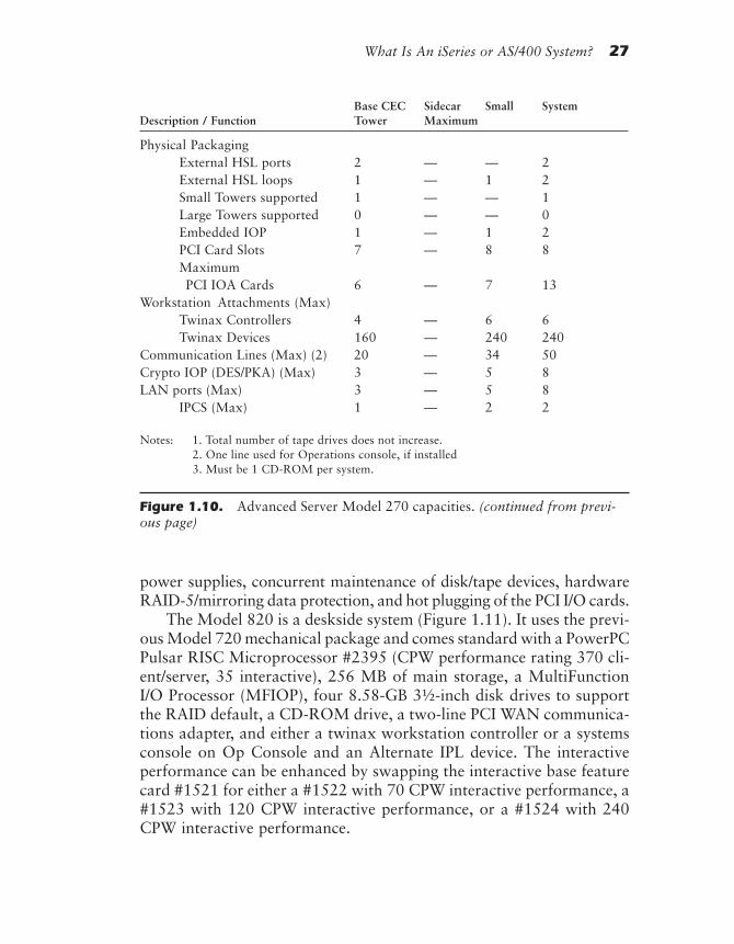
What Is An iSeries or AS/400 System? 27
power supplies, concurrent maintenance of disk/tape devices, hardwareRAID-5/mirroring data protection, and hot plugging of the PCI I/O cards.
The Model 820 is a deskside system (Figure 1.11). It uses the previ-ous Model 720 mechanical package and comes standard with a PowerPCPulsar RISC Microprocessor #2395 (CPW performance rating 370 cli-ent/server, 35 interactive), 256 MB of main storage, a MultiFunctionI/O Processor (MFIOP), four 8.58-GB 3½-inch disk drives to supportthe RAID default, a CD-ROM drive, a two-line PCI WAN communica-tions adapter, and either a twinax workstation controller or a systemsconsole on Op Console and an Alternate IPL device. The interactiveperformance can be enhanced by swapping the interactive base featurecard #1521 for either a #1522 with 70 CPW interactive performance, a#1523 with 120 CPW interactive performance, or a #1524 with 240CPW interactive performance.
Base CEC Sidecar Small SystemDescription / Function Tower Maximum
Physical PackagingExternal HSL ports 2 — — 2External HSL loops 1 — 1 2Small Towers supported 1 — — 1Large Towers supported 0 — — 0Embedded IOP 1 — 1 2PCI Card Slots 7 — 8 8MaximumPCI IOA Cards 6 — 7 13
Workstation Attachments (Max)Twinax Controllers 4 — 6 6Twinax Devices 160 — 240 240
Communication Lines (Max) (2) 20 — 34 50Crypto IOP (DES/PKA) (Max) 3 — 5 8LAN ports (Max) 3 — 5 8
IPCS (Max) 1 — 2 2
Notes: 1. Total number of tape drives does not increase.2. One line used for Operations console, if installed3. Must be 1 CD-ROM per system.
Figure 1.10. Advanced Server Model 270 capacities. (continued from previ-ous page)
rd-ch01.PMD 10/1/2002, 12:24 PM27

28 Exploring IBM ~ iSeries and AS/400e Computers
The Model 820’s performance can be increased by selecting one ofthree processor upgrades (feature codes #2396, #2397, #2398) withCPW performance ratings of 960.0, 1,950.0, and 3,160.0 client/server,respectively, and a base interactive performance of 35 CPW. The #2396Pulsar-based microprocessor interactive performance can be enhancedby swapping the base interactive feature card for increased interactiveperformance features cards #1522, #1523, or #1524 with the afore-mentioned interactive performance values, or #1525 with 560 CPWinteractive performance. The #2397 Istar-based processor is a two-waySymmetrical Multi-Processor (SMP) implementation. The #2397 pro-cessor interactive performance can be enhanced by swapping the baseinteractive feature card for increased interactive performance featurescards #1522, #1523, #1524, or #1525 with the aforementioned inter-active performance values, or #1526 with 1050 CPW interactive per-formance. The #2398 Istar-based processor is a four-way SMP
Figure 1.11. AS/400e server 820 with expansion.
rd-ch01.PMD 10/1/2002, 12:24 PM28

What Is An iSeries or AS/400 System? 29
implementation. The #2398 processor interactive performance can beenhanced by swapping the base interactive feature card for increasedinteractive performance features cards #1522, #1523, #1524, #1525,or #1526 with the aforementioned interactive performance values, or#1527 with 2000 CPW interactive performance.
The Model 820 base structure can house up to twelve disk drives intwo disk cage assemblies (one base and one featured). It can also houseone tape drive, one CD-ROM, an operator panel, and a nine-adapterPortable Computer Interface (PCI) I/O card cage. Up to 16,384 MB ofmain storage can be packaged with the #2397 and #2398 processors.Up to 4,096 MB of main storage can be packaged with the #2395 andup to 8,192 MB of main storage can be packaged with the #2396 pro-cessor. The main storage expansion options used on these models at-tach within the processor cage so that they don’t consume expansionslots. Main storage must be added in matched pairs using 128 MB, 256MB, or 512 MB DIMM storage cards. Disk drive capacity can be in-creased to 4,159.1 GB.
It is also possible to attach up to 2,480 twinaxial workstations, 160communications lines, 3 Crypto IOPs, and 30 local area networks. (Someof the LANs may be displaced by Integrated PC Servers, with a maxi-mum of twelve allowed on a system.) In addition, eight tape libraries(either ½-inch cartridge or 8 mm tape), twelve CD-ROMS or internaltape units, and fourteen optical libraries can be attached. Figure 1.12illustrates the maximum system capacities and performance capabilitiesfor the Model 820.
To achieve the maximum system capacities, it is necessary to attachthe #5075 PCI Expansion small tower, which can increase the total num-ber of disk drives by six with seven additional PCI adapter card slotsand/or the #5074 Disk Expansion Tower, which can hold forty-five diskunits plus two internal tape or CD-ROM devices. The #5074 disk ex-pansion tower includes internal battery backup to allow the completionof data writes in case of power failure. The expansion towers are at-tached using the High-Speed Link technology and may include migra-tions towers with attached expansion units for customers upgradingfrom earlier AS/400 systems. The maximum capacities of the Model820 system can be attained only by using these expansion towers.
The Model 820 system unit can be plugged into standard high-voltageelectrical outlets (180–260 VAC). Utility power failure protection is viaa separately purchased external Universal Power Supply (UPS).
rd-ch01.PMD 10/1/2002, 12:24 PM29
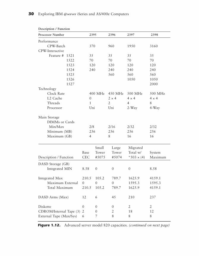
30 Exploring IBM ~ iSeries and AS/400e Computers
Description / Function
Processor Number 2395 2396 2397 2398
PerformanceCPW-Batch 370 960 1950 3160
CPW-InteractiveFeature # 1521 35 35 35 35
1522 70 70 70 701523 120 120 120 1201524 240 240 240 2401525 560 560 5601526 1050 10501527 2000
TechnologyClock Rate 400 MHz 450 MHz 500 MHz 500 MHzL2 Cache 0 2 × 4 4 × 4 4 × 4Threads 1 2 4 8Processor Uni Uni 2-Way 4-Way
Main StorageDIMMs or CardsMin/Max 2/8 2/16 2/32 2/32
Minimum (MB) 256 256 256 256Maximum (GB) 4 8 16 16
Small Large MigratedBase Tower Tower Total w/ System
Description / Function CEC #5075 #5074 *503 × (4) Maximum
DASD Storage (GB)Integrated MIN 8.58 0 0 0 8.58
Integrated Max 210.5 105.2 789.7 1625.9 4159.1Maximum External 0 0 0 1595.3 1595.3Total Maximum 210.5 105.2 789.7 1625.9 4159.1
DASD Arms (Max) 12 6 45 210 237
Diskette 0 0 0 2 2CDROM/Internal Tape (3) 2 0 2 18 12External Tape (Max/Sys) 6 7 8 8 8
Figure 1.12. Advanced server model 820 capacities. (continued on next page)
rd-ch01.PMD 10/1/2002, 12:24 PM30
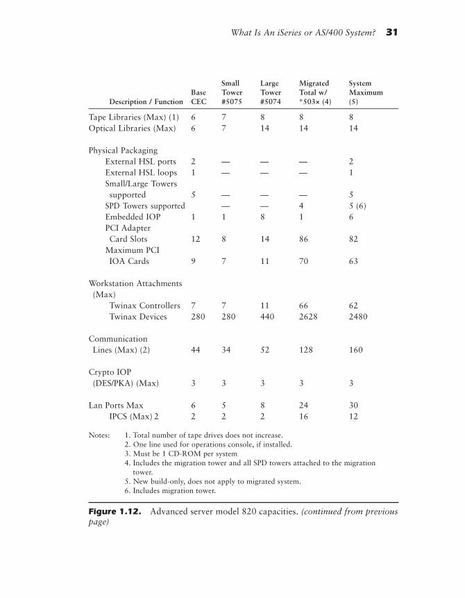
What Is An iSeries or AS/400 System? 31
Small Large Migrated SystemBase Tower Tower Total w/ Maximum
Description / Function CEC #5075 #5074 *503× (4) (5)
Tape Libraries (Max) (1) 6 7 8 8 8Optical Libraries (Max) 6 7 14 14 14
Physical PackagingExternal HSL ports 2 — — — 2External HSL loops 1 — — — 1Small/Large Towerssupported 5 — — — 5
SPD Towers supported — — 4 5 (6)Embedded IOP 1 1 8 1 6PCI AdapterCard Slots 12 8 14 86 82
Maximum PCIIOA Cards 9 7 11 70 63
Workstation Attachments(Max)
Twinax Controllers 7 7 11 66 62Twinax Devices 280 280 440 2628 2480
CommunicationLines (Max) (2) 44 34 52 128 160
Crypto IOP(DES/PKA) (Max) 3 3 3 3 3
Lan Ports Max 6 5 8 24 30IPCS (Max) 2 2 2 2 16 12
Notes: 1. Total number of tape drives does not increase.2. One line used for operations console, if installed.3. Must be 1 CD-ROM per system4. Includes the migration tower and all SPD towers attached to the migration
tower.5. New build-only, does not apply to migrated system.6. Includes migration tower.
Figure 1.12. Advanced server model 820 capacities. (continued from previouspage)
rd-ch01.PMD 10/1/2002, 12:24 PM31

32 Exploring IBM ~ iSeries and AS/400e Computers
iSeries 400 Model 830 Specifics
The Model 830 makes up the high end of the middle range of theAS/400e series family. The Model 830 processors include the two-way,four-way, and eight-way processor versions of AS/400 computers usingthe most powerful of the IStar Microprocessors. This provides for higherperformance, more users, more communications, more storage, andgreater growth capability than the Model 730.
The Model 830 uses a package common with the previous Model640 and S/30, approximately the size of the 1.6-meter rack in the previ-ous S/30 through F 9406 models. The Model 830 uses a High-SpeedLink (HSL) for connecting to the I/O function, the base portion of whichis totally contained within the system unit tower.
The Model 830 (Figure 1.13) is a tall-tower system. The Model 830comes standard with a PowerPC IStar RISC Microprocessor #2400(CPW performance rating 1850 client/server, 70 CPW interactive), 1,024
Figure 1.13. AS/400e server 830.
rd-ch01.PMD 10/1/2002, 12:24 PM32
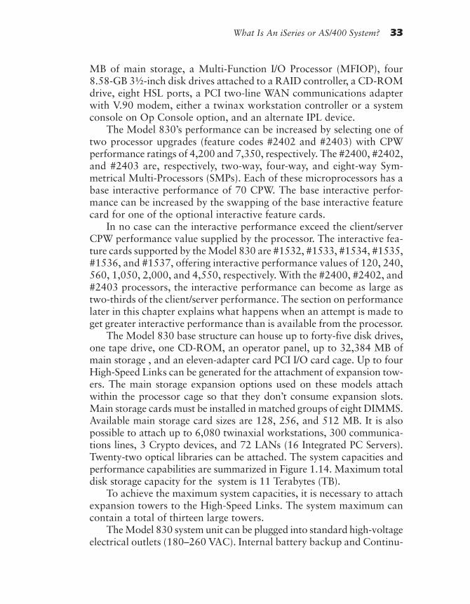
What Is An iSeries or AS/400 System? 33
MB of main storage, a Multi-Function I/O Processor (MFIOP), four8.58-GB 3½-inch disk drives attached to a RAID controller, a CD-ROMdrive, eight HSL ports, a PCI two-line WAN communications adapterwith V.90 modem, either a twinax workstation controller or a systemconsole on Op Console option, and an alternate IPL device.
The Model 830’s performance can be increased by selecting one oftwo processor upgrades (feature codes #2402 and #2403) with CPWperformance ratings of 4,200 and 7,350, respectively. The #2400, #2402,and #2403 are, respectively, two-way, four-way, and eight-way Sym-metrical Multi-Processors (SMPs). Each of these microprocessors has abase interactive performance of 70 CPW. The base interactive perfor-mance can be increased by the swapping of the base interactive featurecard for one of the optional interactive feature cards.
In no case can the interactive performance exceed the client/serverCPW performance value supplied by the processor. The interactive fea-ture cards supported by the Model 830 are #1532, #1533, #1534, #1535,#1536, and #1537, offering interactive performance values of 120, 240,560, 1,050, 2,000, and 4,550, respectively. With the #2400, #2402, and#2403 processors, the interactive performance can become as large astwo-thirds of the client/server performance. The section on performancelater in this chapter explains what happens when an attempt is made toget greater interactive performance than is available from the processor.
The Model 830 base structure can house up to forty-five disk drives,one tape drive, one CD-ROM, an operator panel, up to 32,384 MB ofmain storage , and an eleven-adapter card PCI I/O card cage. Up to fourHigh-Speed Links can be generated for the attachment of expansion tow-ers. The main storage expansion options used on these models attachwithin the processor cage so that they don’t consume expansion slots.Main storage cards must be installed in matched groups of eight DIMMS.Available main storage card sizes are 128, 256, and 512 MB. It is alsopossible to attach up to 6,080 twinaxial workstations, 300 communica-tions lines, 3 Crypto devices, and 72 LANs (16 Integrated PC Servers).Twenty-two optical libraries can be attached. The system capacities andperformance capabilities are summarized in Figure 1.14. Maximum totaldisk storage capacity for the system is 11 Terabytes (TB).
To achieve the maximum system capacities, it is necessary to attachexpansion towers to the High-Speed Links. The system maximum cancontain a total of thirteen large towers.
The Model 830 system unit can be plugged into standard high-voltageelectrical outlets (180–260 VAC). Internal battery backup and Continu-
rd-ch01.PMD 10/1/2002, 12:24 PM33
34 Exploring IBM ~ iSeries and AS/400e Computers
Description / Function
Processor Number 2400 2402 2403
PerformanceCPW-Batch 1850 4200 7350CPW-InteractiveFeature # 1531 70 70 70
1532 120 120 1201533 240 240 2401534 560 560 5601535 1050 1050 10501536 2000 20001537 4550
TechnologyClock Rate 400 MHz 540 MHz 500 MHzL2 Cache 2 × 4 4 × 4 4 × 4Threads 4 8 16Processor 2-Way 4-Way 8-Way
Main StorageDIMMs or CardsMin/Max 8/64 8/64 8/64
Minimum (GB) 1 1 1Maximum (GB) 32 32 32
Small Large Migrated SystemBase Tower Tower Total w/ Maximum
Description / Function CEC #5075 #503 × (4) w/#5077 (5)
DASD Storage (GB)Integrated MIN 8.58 0 0 0 8.58Integrated Max 789.7 789.7 1625.9 2499.6 11055.8MaximumExternal 0 0 1595.3 2473.9 2473.9
Total Maximum 789.7 789.7 1625.9 2499.6 11055.8DASD Arms (Max) 596 630Diskette 0 0 2 2 2CDROM/InternalTape (3) 2/1 2/2 18/17 18/17 18/17
External Tape(Max/Sys) 8 10 8 10 10
Figure 1.14. Advanced server model 830. (continued on next page)
rd-ch01.PMD 10/1/2002, 12:24 PM34

What Is An iSeries or AS/400 System? 35
Description / Function Base Small Large Migrated SystemCEC Tower Tower Total w/ Maximum
#5075 #503 × (4) w/#5077 (5)
Tape Libraries(Max) (1) 8 10 8 10 10
Optical Libraries(Max) 8 11 14 22 22
Physical PackagingExternal HSL ports 8 — — — 8External HSL loops 4 — — — 4Small Towerssupported 0 — — — 0
Large Towerssupported 13 — — — 13
Embedded IOP 0 0 2 0 2PCI AdapterCard Slots 14 14 86 270 452
Maximum PCIIOA Cards 11 11 70 216 359
Workstation Attachments(Max)
Twinax Controllers 9 11 66 175 152Twinax Devices 360 440 2628 7000 6080
Communication Lines(Max) (2) 40 52 128 250 300
Crypto IOP(DES/PKA) (Max) 3 3 3 3 3
LAN Ports (Max) 6 8 24 48 72IPCS (Max) 2 2 16 16 16
Notes: 1. Total number of tape drives does not increase.2. One line used for operations console, if installed.3. Must be 1 CD-ROM per system.4. Includes the migration tower and all SPD towers attached to the migration tower.5. Includes second migration tower and all SPD towers attached to that tower.6. New build only, does not apply to migrated systems.
Figure 1.14. Advanced server model 830. (continued from previous page)
rd-ch01.PMD 10/1/2002, 12:24 PM35

36 Exploring IBM ~ iSeries and AS/400e Computers
ously Powered Main Storage (CPM) provide base utility power failureprotection.
iSeries 400 Model 840 Specifics
The Model 840 makes up the high end of the AS/400 family. The Model840 includes twelve-way and twenty-four-way versions of Istar micro-processors. Using the Istar microprocessor provides higher performance,more users, more communications, more storage, and greater growthcapability than either the Model 830 or the Model 820. The Model 840uses a common package approximately the size of the 1.6-meter rack inthe previous 740 Model plus a separate I/O function tower just as in the740 Model. Both the processor unit and the I/O function tower operatefrom separate 240-V line sources. The I/O function tower connects tothe processor unit tower by means of a new technology interface cablecalled High-Speed Link (HSL), which allows a separation between anytwo units on a loop of up to fifteen meters.
The Model 840 reuses the same package as the Model 740 (Figure1.15). It comes standard with a twelve-way Symmetrical Multi-Processor(SMP), PowerPC Istar RISC Microprocessor #2418 (CPW performancerating 10,000 client/server, 120 CPW interactive), 4,096 MB of main stor-
Figure 1.15. AS/400e server 840 and e-server 840-SBI.
rd-ch01.PMD 10/1/2002, 12:24 PM36

What Is An iSeries or AS/400 System? 37
age, a Multi-Function I/O Processor (MFIOP), four 8.58 GB 3½-inch diskdrives, a CD-ROM drive, a sixteen-port HSL card, a PCI two-line WideArea Network (WAN) communications adapter, either a twinax worksta-tion controller or a system console on Op Console, and a logic cage ca-pable of containing eleven PCI adapter cards and battery backup units.
The Model 840 can be upgraded to a twenty-four-way PowerPCIstar RISC Microprocessor #2420 (CPW performance rating 16,500client/server, 120 interactive). The base interactive performance can beincreased by swapping the base interactive processor function for oneof the interactive feature processors #1541, #1542, #1543, #1544,#1545, #1546, or #1547, with interactive CPW value ratings of 240,560, 1,050, 2,000, 4,550, 10,000, or 16,500, respectively. In no casecan the interactive performance value exceed the client/server perfor-mance value. The section on performance later in this chapter explainswhat happens when an attempt is made to get greater interactive per-formance than is available from the processor.
Three new processor features offer “On Demand” capacity for ASPs,ISPs, and dynamic growth customers. If one of these processor optionsare ordered, activation can be temporary, at the time of server installationand after each new activation, for a period of fourteen days, and requiresno IPL activity, or permanent, in which case the activation code is bothposted to the Web and mailed, and requires the entry of the activationcode at the server. The processor feature codes are: #2416 with eightactive processors and 4 on demand standby processors, #2417 with twelveactive processors and six on demand standby processors, and #2419 witheighteen active processors and six on demand standby processors. OnDemand standby processors are not paid for until activated.
The Model 840 base structure can house up to forty-five 3½-inchdisk drives, one tape drive, one CD-ROM, an operator panel, up to97,152 MB of main storage in increments of four main storage cardseach, and an eleven-adapter PCI card cage. The main storage expansionoptions used on these models attach within the processor tower so thatthey don’t consume I/O expansion slots.
Main storage must be plugged in in groups of four cards. Mainstorage card sizes are 1,024, 2,048, 4,096, and 8,192 MB. It is alsopossible to attach up to 7,000 twinaxial workstations, 400 communica-tions lines, 3 Crypto devices, and 96 LANs. Up to sixteen Integrated PCServers may be used instead of the LANs, where an IPCS can containtwo LANs. Twenty-six optical libraries can be attached. The #5074 Stor-
rd-ch01.PMD 10/1/2002, 12:24 PM37

38 Exploring IBM ~ iSeries and AS/400e Computers
age Expansion Units may be added to the base I/O tower to increase thetotal number of 3½-inch disk drives for each unit. A maximum diskcapacity of 18,952 TB is supported. The total system capacities andperformance capabilities of the Model 840 are summarized in Figure1.16. To achieve the maximum system capacities, it is necessary to at-tach expansion towers to each of the eight possible High-Speed Loops.
The Model 840 system unit processor tower and the base I/O towermust be plugged individually into standard high-voltage electrical out-lets (180–260 VAC). Internal battery backup and Continuously Pow-ered Main Storage (CPM) provide base utility power failure protection.To extend the retention interval, the external battery backup featuremust be installed.
To accommodate users with the previous nineteen-inch rack-mountedequipment, the new 8X0-based models can interface compatibly withthat equipment. It is also possible to perform processor performanceupgrades within the new models. These models use the same OS/400operating system as the rest of the AS/400 family. In fact, the operatingsystem is now bundled with the hardware, which means that when oneof these-systems, whether it is used as a server or a general-purposesystem, is ordered, the operating system is included with that order. Forprevious hardware models, an operating system license was orderedseparately from the hardware. For clarity, we refer to all AS/400e serv-ers as Application Systems. When we discuss a specific product, thespecific name is used.
Server Preload Packages
The server’s software preload capability continues to be supported onthe Models 720, 730, 740, 820, 830, and 840. The customer can de-fine the interactive workload desired to be supported by selecting theinteractive workload feature. Applications software can be selectedfrom a set of tested business partners. The applications software ingeneral fits into an Enterprise Resource Planning environment. Thefollowing list identifies the companies whose software can be preloaded,the program name, a summary of application areas addressed by theprogram, and links to the program provider’s Internet site. This soft-ware preload capability is also available on the AS/400e servers mod-
rd-ch01.PMD 10/1/2002, 12:24 PM38

What Is An iSeries or AS/400 System? 39
Description / Function
Processor Number 2418 2420
PerformanceCPW-Batch 10000 16500CPW-InteractiveFeature # 1541 120 120
1542 240 2401543 560 5601544 1050 10501545 2000 20001546 4550 45501547 10000 100001548 16500
TechnologyClock Rate 500 MHz 500 MHzL2 Cache 8 × 4 8 × 4Threads 24 48Processor 12-Way 24-Way
Main StorageDIMMs orCards Min/Max 4/16 4/16
Minimum (GB) 4 4Maximum (GB) 96 96
Large Migrated SystemBase Tower Total Maximum
Description / Function CEC #5074 w/#5077 (5)
DASD Storage (GB)Integrated Min 8.58 0 0 8.58Integrated Max 789.7 789.7 4292.9 18952.9Maximum External 0 0 4260.6 4260.6Total Maximum 789.7 789.7 4294.6 18952.9
DASD Arms (Max) 596 1080Diskette 0 0 2 2CD-ROM 2/1 2/2 18/17 24/26External Tape (Max/Sys) 8 11 14 26Tape Libraries (Max) (1) 8 11 14 26Optical Libraries (Max) 8 11 22 26
Figure 1.16. Advanced server model 840 capacities. (continued on next page)
rd-ch01.PMD 10/1/2002, 12:24 PM39
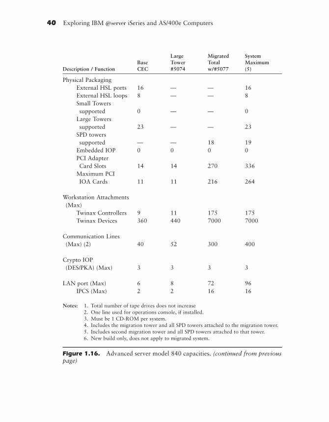
40 Exploring IBM ~ iSeries and AS/400e Computers
Large Migrated SystemBase Tower Total Maximum
Description / Function CEC #5074 w/#5077 (5)
Physical PackagingExternal HSL ports 16 — — 16External HSL loops 8 — — 8Small Towerssupported 0 — — 0
Large Towerssupported 23 — — 23
SPD towerssupported — — 18 19
Embedded IOP 0 0 0 0PCI AdapterCard Slots 14 14 270 336
Maximum PCIIOA Cards 11 11 216 264
Workstation Attachments(Max)
Twinax Controllers 9 11 175 175Twinax Devices 360 440 7000 7000
Communication Lines(Max) (2) 40 52 300 400
Crypto IOP(DES/PKA) (Max) 3 3 3 3
LAN port (Max) 6 8 72 96IPCS (Max) 2 2 16 16
Notes: 1. Total number of tape drives does not increase2. One line used for operations console, if installed.3. Must be 1 CD-ROM per system.4. Includes the migration tower and all SPD towers attached to the migration tower.5. Includes second migration tower and all SPD towers attached to that tower.6. New build only, does not apply to migrated system.
Figure 1.16. Advanced server model 840 capacities. (continued from previouspage)
rd-ch01.PMD 10/1/2002, 12:24 PM40
What Is An iSeries or AS/400 System? 41
els 170 and 270. IBM Solutions Packaging website = http://www.ibm.com/as400/developer/packaging.
SSA—BPCS Client/Server or Mixed Mode
BPCS Client/Server is a comprehensive set of integrated client/serverapplications that addresses the core system needs of industrial-sectorenterprises on a global scale. BPCS Client/Server covers ConfigurableEnterprise Financials applications, Supply Chain Management applica-tions, Multi-Mode Manufacturing applications, and CIM applications,as well as Electronic Commerce applications such as EDI. BPCS Client/Server is based on SSA’s proven object technology foundation, whichensures that it operates identically from an end-user’s perspective acrossany supported AS/400 server.
SSA website = http://www.ssax.com
MAPICS—MAPICS XA
MAPICS is the most widely used manufacturing software system in theworld. Its modular design offers more than forty applications tocustom-configure the right solution for a specific manufacturing situation.
MAPICS website = http://www.mapics.com
JBA International—JBA System 21
This software contains an integrated enterprise-wide suite of supply chainapplications that provide manufacturing, financial, service management,customer service, and logistics solutions with expanded functional fitfor the automotive, beverage, food, and apparel and footwear sectors.
JBA website = http://www.jbaworld.com
International Business Systems—IBS–ASW
ASW covers an extensive range of functions in modules for:
• Management information
• Data warehousing
rd-ch01.PMD 10/1/2002, 12:24 PM41

42 Exploring IBM ~ iSeries and AS/400e Computers
• Sales and distribution
• Financial management
• Manufacturing
IBS website = http://www.ibs.se and http://www.ibsus.com.San Francisco Project (discussed in Chapter 4) = http://www.
softmall.com/sf
Intentia—The Movex System
The Movex System is a fully integrated ERP system with a high degreeof functionality for manufacturers and distributors.
Intentia website = http://www.intentia.com
Baan—BaanERP
BaanERP is a suite of components including sales, warehousing, purchas-ing, manufacturing, projects and service, finance, technology, and architec-ture. Baan is a world leader in innovative application solutions for theextended industry with over 4,000 customer sites in over sixty countries.The BaanERP solution can be preloaded on the AS/400e servers (exceptModel 150).
Baan/400 newsletter (subscribe by emailing) = [email protected] website = http://www.baan.com
Infinium—Infinium Suite for IBM AS/400
The Infinium Series for the IBM AS/400 has been designed, and optimized,for the AS/400. The Infinium Suite for AS/400 runs native to the AS/400. Itincludes financial management, materials management, human resources,and process manufacturing solutions. The Infinium Suite for AS/400 in-cludes five packages, which may be ordered separately or as a suite:
• Infinium Human Resources
• Infinium Financial Management
• Infinium Materials Management
rd-ch01.PMD 10/1/2002, 12:24 PM42

What Is An iSeries or AS/400 System? 43
• Infinium Process Manufacturing
• Infinium AS/400e Extensions
Infinium website = http://www.infinium.com/html/as’400’products.html
Acacia Technologies—Acacia Suite for AS/400
Acacia Technologies offers a full suite of enterprise-wide applications andtools designed to run manufacturing and distribution enterprises. Theseproducts include Enterprise Resource Planning (ERP), Warehouse Man-agement System (WMS), Advanced Planning and Scheduling (ASP), DataWarehousing, and a variety of powerful tools. All Acacia Technologiesproducts are designed exclusively for the AS/400 client/server platform.Also, all current releases of Acacia products are year 2000 compliant.
Acacia website = http://www.acaciatech.com
Lilly Software Associates—Visual Manufacturing
Visual Manufacturing is Lilly Software Associates’ comprehensive ERPsolution for manufacturers. Designed to accommodate job-shop,engineer-to-order, make-to-order, make-to-stock, and mixed-mode manu-facturing environments, VISUAL Manufacturing provides the technol-ogy needed to improve productivity, control costs, and increase profits.
Lilly Software Associates website = http://www.lillysoftware.com
SAP-Base R/3 Package
For over two years, IBM has been delivering preloaded R/3 software to AS400customers all over the world. This offering provides a quick, simple start inworking with SAP R/3. It provides the option to have the base R/3 applica-tion installed in a two-tier or three-tier configuration, offering a savings of atleast three fewer days of on-site install time. Upon arrival, the system is readyfor consultants to begin R/3 customization and configuration.
SAP—Ready to Run R/3
Customers will find SAP’s Ready to Run R/3 solution on AS/400e to beamong the easiest to use and fastest to deploy, utilizing a unique selec-tion of hardware and software management tools and support materi-
rd-ch01.PMD 10/1/2002, 12:24 PM43

44 Exploring IBM ~ iSeries and AS/400e Computers
als as part of the package. Ready to Run R/3 offerings on AS/400e ineasy-to-order packages for 25, 50, 75, 100, 150, 250, and 500 R/3 us-ers are available as a single footprint solution, eliminating the hiddenmulti-tier costs of competitive offerings. Predefined R/3 Users and Pro-files, Operating Modes, System Maintenance and Backup Schedules,and Alert Monitor threshold values are just a few of the softwarecustomization options available as part of the preload package.
SAP website = http://www.sap.com.menu
Custom Application Servers
The custom application servers are the SB1, SB2, and SB3—second-tierservers for compute-intensive environments. The SB1 was described inExploring IBM AS/400 Computers, 9th edition (IBM documentG325-0400, Maximum Press), which for the sake of brevity will not berepeated in this edition. As a result of their intended use in acompute-intensive environment, the custom application servers have alarge main storage with tight restrictions on the other I/O functionsavailable.
iSeries 400 Custom Application Server Model SB2
The Model SB2 is a constrained version of the eight-way processorModel 830 and comes standard with an eight-way PowerPC Istar RISCMicroprocessor (125,888 normalized FI Dialog Steps per hour at 65percent CPU utilization), 12,288 MB of main storage, a Multi-FunctionI/O Processor (MFIOP), four 8.58-GB 3½-inch disk drives, a CD-ROMdrive, two High-Speed Loops, a PCI two-line WAN communicationsadapter with V.90 modem, either a Twinax workstation controller or asystem console on Op Console, and a PCI card cage capable of elevenPCI adapters, one of which must be a RAID controller.
The Model 830-SB2 base structure can house one tape drive, oneCD-ROM, and an operator panel. Main storage may not be increasedbeyond the base 12,288 MB. It is also possible to attach up totwenty-eight twinaxial workstations, thirty-two communications lines,three Crypto devices, and six LANs. Two optical libraries or four exter-nal tape libraries can be attached. The Model SB2 capacities are sum-marized in Figure 1.17.
rd-ch01.PMD 10/1/2002, 12:24 PM44

What Is An iSeries or AS/400 System? 45
The Model SB2 system unit processor tower and the base I/O towermust be plugged individually into standard high-voltage electrical out-lets (180–260 VAC). Internal battery backup and Continuously Pow-ered Main Storage (CPM) provide base utility power failure protection.
Description / Function
Processor Number 2315
PerformanceCPW-Batch 7350CPW-Interactive 0
TechnologyClock Rate 540 MHzL2 Cache 8 × 4Threads 16Processor 8-Way
Main StorageDIMMs orCards Min/Max 48/48
Minimum (GB) 12Maximum (GB) 12
MigratedBase Total System
Description / Function CEC w/#5077 Maximum
DASD Storage (GB)Physical Base 34.3 34.3Physical Max 70.1 70.1Logical Max(Raid 17.54 GB) 52.6 52.6
DASD Arms (Max) 4 4Diskette 0 2 2CDROM 2/1 3 3External Tape (Max/Sys) 5 4 5Tape Libraries (Max) (1) 4 4 4Optical Libraries (Max) 2 2 2
Figure 1.17. Third tier server Model SB2 capacity. (continued on next page)
rd-ch01.PMD 10/1/2002, 12:24 PM45

46 Exploring IBM ~ iSeries and AS/400e Computers
To extend the retention interval to forty-eight hours, it is necessary toinstall the external battery backup feature.
The SB2 application server runs SAP-BaseR/3 Package and BaanERPsoftware meeting the full range of business requirements, including fi-nancial accounting and controlling, sales and distribution, materialsmanagement, production planning, and human resources management.Information and early-warning systems are also available. Business In-
Physical PackagingExternal HSL ports 4 — 4External HSL loops 2 — 2Small Towerssupported 0 — 0
Large Towerssupported 0 — 0
5077 Towerssupported 1 — 1
Embedded IOP 14 — 14PCI AdapterCard Slots 11 — 11
Maximum PCIIOA Cards 3 2 3
Workstation Attachments(Max)
Twinax Controllers 1 1 1Twinax Devices 28 28 28
Communication Lines(Max) (2) 32 12 32
Crypto IOP(DES/PKA) (Max) 3 1 3
LAN port (Max) 6 6 6IPCS (Max) 2 2 2
Notes: 1. Total number of tape drives does not increase.2. One line used for Operations console, if installed.3. Must be 1 CDROM per system.
Figure 1.17. Third tier server Model SB2 capacity. (continued from previouspage)
rd-ch01.PMD 10/1/2002, 12:24 PM46

What Is An iSeries or AS/400 System? 47
formation Warehouse can edit external and internal data to supportdecision making at necessary corporate levels.
iSeries 400 Custom Application Server Model SB3
The Model SB3 is a constrained configuration of the Model 840 and comesstandard with a twelve-way PowerPC Istar RISC Microprocessor (185,533normalized FI Dialog Steps per hour at 65 percent CPU utilization), 16,384MB of main storage, a MultiFunction I/O Processor (MFIOP), four 8.58-GB3½-inch disk drives, a CD-ROM drive, four High-Speed Loops, a PCItwo-line WAN communications adapter with V.90 modem, either a twinaxworkstation controller or a system console on Op Console, and a PCI cardcage that can hold eleven PCI I/O adapters.
The Model SB3’s performance may be increased by swapping thetwelve-way processor with a twenty-four-way processor (feature code#2318) for 325,878 normalized FI Dialog Steps per hour at 65 percentCPU utilization. Both of the processor configurations supported on theModel SB3 are Symmetrical Multi-Processors (SMPs).
The Model SB3 base structure can achieve a maximum disk capac-ity of 122.7 GB to enable mirroring of the disk data, one tape drive, oneCD-ROM, and an operator panel. Main storage on the #2318 proces-sors accommodates 24,576 MB of main storage. It is also possible toattach up to twenty-eight twinaxial workstations, thirty-two communi-cations lines, three Crypto devices, and four LANs with two IPCS con-trollers. Two optical libraries can be attached, as can four tape libraries.The Model SB3 capacities are summarized in Figure 1.18.
The Model SB3 system unit processor tower and the base I/O towermust be plugged individually into standard high-voltage electrical out-lets (180–260 VAC). Internal battery backup and Continuously Pow-ered Main Storage (CPM) provide base utility power failure protection.To extend the retention interval, it is necessary to install the externalbattery backup feature.
The SB3 application server runs SAP-BaseR/3 Package and BaanERPsoftware, meeting the full range of business requirements, including fi-nancial accounting and controlling, sales and distribution, materialsmanagement, production planning, and human resources management.Information and early-warning systems are also available. Business In-formation Warehouse can edit external and internal data to supportdecision making at necessary corporate levels.
rd-ch01.PMD 10/1/2002, 12:24 PM47

48 Exploring IBM ~ iSeries and AS/400e Computers
Description / Function
Processor Number 2316 2318
PerformanceCPW-Batch 10000 16500CPW-Interactive 0 0
TechnologyClock Rate 500 MHz 500 MHzL2 Cache 8 × 4 8 × 4Threads 24 48Processor 12-Way 24-Way
Main StorageDIMMs orCards Min/Max 8/8 12/12
Minimum (GB) 16 24Maximum (GB) 16 24
DASD Storage (GB)Physical Base 34.3 34.3Physical Max 105.2 140.3Logical Max(Raid 17.54 GB) 87.7 122.7
Arms 6 8
MigratedBase Total System
Description / Function CEC w/#5077 Maximum
Diskette 0 2 2CD-ROM 2/1 3 3External Tape (Max/Sys) 7 4 7Tape Libraries (Max) (1) 4 4 4Optical Libraries (Max) 2 2 2
Diskette 0 2 2CD-ROM/InternalTape (3) 2/1 3 3
External Tape(Max/Sys) 7 4 7
Tape Libraries (Max) (1) 4 4 4
Figure 1.18. Third tier server Model SB3 capacity. (continued on next page)
rd-ch01.PMD 10/1/2002, 12:24 PM48

What Is An iSeries or AS/400 System? 49
MigratedBase Total System
Description / Function CEC w/#5077 Maximum
Optical Libraries (Max) 2 2 2
Physical PackagingExternal HSL ports 8 — 8External HSL loops 4 — 4Small Towerssupported 0 — 0
Large Towerssupported 0 — 0
5077 Towerssupported 1 — 1
Embedded IOP 14 — 14PCI AdapterCard Slots 11 — 11
Maximum PCIIOA Cards 3 2 3
Workstation Attachments(Max)
Twinax Controllers 1 1 1Twinax Devices 28 28 28
Communication Lines(Max) (2) 32 12 32
Crypto IOP(DES/PKA) (Max) 3 1 3
LAN ports (Max) 6 6 6IPCS (Max) 2 2 2
Notes: 1. Total number of tape drives does not increase.2. One line used for operations console, if installed.3. Must be 1 CD-ROM per system.4. As only 3 controllers and 2 towers are allowed on the SB3,
max of 4 HSL ports and 2 HSL loops are unable to attachtowers. Other ports and loops are usable for clustering only.
Figure 1.18. Third tier server Model SB3 capacity. (continued from previouspage)
rd-ch01.PMD 10/1/2002, 12:24 PM49

50 Exploring IBM ~ iSeries and AS/400e Computers
iSeries 400 Dedicated Servers for Domino
There are three dedicated servers for Domino offered by the AS/400product line.
Those servers include the 170D, the 270D, and the 820D. Theseservers have been tuned to match the requirements for Lotus DominoR5 workloads, including Domino web serving, applications, and mail.Within the design point, non-Domino workloads should consume lessthan 10–15 percent of the available CPU CPW capability, whereasDomino workloads can consume 100 percent of that capability. Nointeractive processing capability is available for application use beyondthe impact of the activities of a single systems administrator.
When deciding whether to select a Dedicated Server for Dominomodel or a traditional AS/400e server model, you should consider thefollowing:
Dedicated Server for Domino is best for . . .
• Domino Mail
• Domino applications
• Mixed Domino workload
• Domino web serving
• Domino web front-end to AS/400 Line-of-Business (LOB) server
Traditional AS/400e server is best for . . .
• Domino and other AS/400 Line-of-Business (LOB) applicationson the same server
• Large-enterprise user populations
• DB2 database integration on the same server
Dedicated Server for Domino Model 170D
Three processor options are allowed, ranging in performance from 1,300Simple Mail Users (SMU) to 4,300 Simple Mail Users. It is not possible
rd-ch01.PMD 10/1/2002, 12:24 PM50

What Is An iSeries or AS/400 System? 51
to upgrade to the Model 170D from any other model or from the Model170D to any other model. Main storage feature cards are not customerinstalled; if the customer orders additional main storage, IBM will in-stall the main storage and any other features also ordered.
The #2407 Processor supports 1,300 SMU and can be upgraded tothe #2408 or #2409 processor, which supports 2,300 and 4,300 SMU,respectively. The Main Storage maximum capacity for each processor is4,096 MB with a maximum disk capacity of 175.1 GB. System capaci-ties in all other respects are the same as for the Model 170e server.
iSeries 400 Dedicated Server for Domino Model 270D
Three processor options are allowed, ranging in performance from 2,400Simple Mail Users (SMU) to 7,580 Simple Mail Users. The Model 270Dalso supports the Mail and Calendar User environment ranging from1,600 MCU on the lowest-performing processor to 5,050 MCU on thehighest-performing processor offered. It is not possible to upgrade tothe Model 270D from any other model or from the Model 270D to anyother model. Main storage feature cards are not customer installed; ifthe customer orders additional main storage, IBM will install the mainstorage and any other features also ordered.
The #2422 Processor supports 1,300 SMU and 1,600 MCU and canbe upgraded to the #2423 or #2424 processor, which supports 3,860 and7,580 SMU, or 2,570 and 5,050 MCU, respectively. The Main Storagemaximum capacity for the #2422 processor is 4,096 MB with a maxi-mum disk capacity of 421.1 GB. The Main Storage capacity for the #2423and #2424 processors is 8,192 MB with the same maximum DASD ca-pacity of 421.1 GB. The relative processor ratings are 50 CPW, 100 CPW,and 200 CPW for the #2422, #2423, and #2424 processors, respectively.These processor ratings presume a Domino workload with no interactiveworkload other than that needed by the system administrator. Systemcapacities in all other respects are the same as for the Model 270e server.LPAR is not available on the Model 270D. Figure 1.19 shows the capaci-ties for the Dedicated Server for Domino Model 270D.
iSeries 400 Dedicated Server for Domino Model 820D
Three processor options are allowed, ranging in performance from 3,860Simple Mail Users (SMU) to 14,840 Simple Mail Users. The Model 270Dalso supports the Mail and Calendar User environment, ranging from
rd-ch01.PMD 10/1/2002, 12:24 PM51

52 Exploring IBM ~ iSeries and AS/400e Computers
2,570 MCU on the lowest-performing processor to 9,890 MCU on thehighest-performing processor offered. It is not possible to upgrade tothe Model 820D from any other model or from the Model 820D to anyother model. Main storage feature cards are not customer installed; ifthe customer orders additional main storage, IBM will install the mainstorage and any other features also ordered.
The #2425 Processor supports 3,860 SMU and 2,570 MCU andcan be upgraded to the #2426 or #2427 processor, which supports 8,420and 14,840 SMU, or 5,610 and 9,890 MCU, respectively. The MainStorage maximum capacity for the #2425 processor is 8,192 MB, witha maximum disk capacity of 4 TB. The Main Storage capacity for the
Description / Function
Processor Number 2422 2423 2424
PerformanceCPW-Batch 370 950 2000CPW-Interactive 0 0 0
TechnologyClock Rate 400 MHz 450 MHz 450 MHzL2 Cache 0 2 × 4 4 × 4Threads 2 2 4Processor Uni Uni 2-Way
Main Storage DIMMs orCards Min/Max 2/8 2/16 2/16
Minimum (GB) 256 256 256Maximum (GB) 4 8 8
MigratedBase Total System
Description / Function CEC Sidecar w/#5077 Maximum
DASD Storage (GB)Integrated Min 8.58 0 0 8.58Integrated Max 105.2 210.5 105.2 421.1Maximum External 0Total Maximum 105.2 210.5 105.2 421.1DASD Arms (Max) 6 12 6 24CD-ROM 2 — 0 2External Tape (Max/Sys) 3 — 3 3
Figure 1.19. Dedicated server for Domino Model 270D capacities. (continuedon next page)
rd-ch01.PMD 10/1/2002, 12:24 PM52

What Is An iSeries or AS/400 System? 53
#2426 and #2427 processors is 16,384 MB, with the same maximumDASD capacity of 4 TB. The relative processor ratings are 100 CPW,200 CPW, and 300 CPW for the #2422, #2423, and #2424 processors,respectively. The #2426 processor is a two-way, and the #2427 is afour-way processor. These processor ratings presume a Dominoworkload with no interactive workload other than that needed by thesystem administrator. System capacities in all other respects are the sameas for the Model 820e server. Figure 1.20 shows the capacities for theDedicated Server for Domino Model 820D.
MigratedBase Total System
Description / Function CEC Sidecar w/#5077 Maximum
Tape Libraries (Max) (1) 3 — 3 3Optical Libraries (Max) 3 — 4 4Physical Packaging
External HSL ports 2 — — 2External HSL loops 1 — — 1Small Towerssupported 1 — — 1
Large Towerssupported 0 — — 0
Embedded IOP 1 — 1 2PCI Card Slots 7 — 8 15Maximum PCIIOA Cards 6 — 7 13
Workstation Attachments (Max)Twinax Controllers 4 — 6 6Twinax Devices 160 — 240 240
Communications Lines (Max) 20 — 34 50Crypto IOP(DES/PKA) (Max) 3 — 3 3
LAN ports (Max) 3 — 5 8IPCS (Max) 1 — 2 3
Notes: 1. Total number of tape drives does not increase.2. One line used for operations console, if installed.3. Must be 1 CD-ROM per system.
Figure 1.19. Dedicated server for Domino Model 270D capacities. (continuedfrom previous page)
rd-ch01.PMD 10/1/2002, 12:24 PM53

54 Exploring IBM ~ iSeries and AS/400e Computers
System Availability
Since their inception, the AS/400 systems have had availability as a tar-get. The average single AS/400 system in 1997 had an availability ofgreater than 99.9 percent, with average unplanned outages of less thannine hours per year. Daily reports are accumulated on greater than 87,000AS/400 systems in the United States. These reports show that on AS400
Description / Function
Processor Number 2425 2426 2427
PerformanceCPW-Batch 950 2000 3200CPW-Interactive 0 0 0Feature #
TechnologyClock Rate 450 MHz 500 MHz 500 MHzL2 Cache 2 x 4 4 x 4 4 x 4Threads 2 4 8Processor Uni 2-Way 4-Way
Main StorageDIMMs or CardsMin/Max 2/16 2/32 2/32
Minimum (MB) 256 256 256
Maximum (GB) 8 16 16
Base Small LargeCEC Tower Tower System
Description / Function #5075 #5074 (5) Maximum
DASD Storage (GB)Integrated MIN 8.58 0 0 8.58Integrated Max 210.5 105.2 789.7 4159.1Maximum External 0 0 0 0Total Maximum 210.5 105.2 789.7 4159.1DASD Arms (Max) 12 6 45 237Diskette 0 0 0 0CD-ROM/InternalTape (3) 2 0 2 12
Figure 1.20. Dedicated server for Domino Model 820D capacities. (continuedon next page)
rd-ch01.PMD 10/1/2002, 12:24 PM54

What Is An iSeries or AS/400 System? 55
systems shipped since January 1996, the average interval between hard-ware problems is sixty-one months. These results were accomplishedthrough a combination of hardware and software actions. The hard-ware and software items described next identify the actions taken bythe AS/400 to achieve that availability. The five items described afterthe hardware and software actions are what take the AS/400 to an avail-ability of 99.99 percent.
Description / Function Base Small Large SystemCEC Tower Tower Maximum#5075 #5074 (5)
External Tape (Max/Sys) 6 7 8 8Tape Libraries (Max) (1) 6 7 8 8Optical Libraries (Max) 6 7 14 14Physical Packaging
External HSL ports 2 — — 2External HSL loops 1 — — 1Small/Large Towers\supported 5 — — 5
Embedded IOP 1 1 8 6PCI AdapterCard Slots 12 8 14 82
Maximum PCIIOA Cards 9 7 11 63
Workstation Attachments(Max)
Twinax Controllers 7 7 11 62Twinax Devices 280 280 440 2480
CommunicationLines (Max) (2) 44 34 52 160
Crypto IOP(DES/PKA) (Max) 3 3 3 3
Lan Ports Max 6 5 8 30IPCS (Max) 2 2 2 12
Notes: 1. Total number of tape drives does not increase.2. One line used for operations console, if installed.3. Must be 1 CD-ROM per system.
Figure 1.20. Dedicated server for Domino Model 820D capacities. (continuedfrom previous page)
rd-ch01.PMD 10/1/2002, 12:24 PM55

56 Exploring IBM ~ iSeries and AS/400e Computers
On the hardware side, things like battery backup and continuouslypowered main storage protect against utility failures and the loss ofdata that could result from those failures. Redundant bulk power sup-plies and independent redundant local voltage regulators protect againstpower system failures. RAID-5, mirroring, and redundant write cacheprotect against data loss from disk unit failures, whereas concurrentmaintenance allows the repair of those failures without loss of the sys-tem to your users. System Power Control Network (SPCN) turns thesystem and its remote components on and off at the same time andmonitors the remote units to enable maintenance actions before theycause a catastrophic system failure.
From the software side, items like commitment control andjournaling, auxiliary storage pools, system-managed access paths,save-while-active, S/R parallelism, hierarchical storage management,BRMS, and ADSM (combined with the pretesting of the integrated op-erating system and applications code) reduce the duration of the recov-ery actions needed if an outage does occur. Figure 1.21 describes thehierarchy of actions needed to achieve 100 percent availability.
The following paragraphs describe the options offered as well as thechoices a customer must make to increase the AS/400 availability. In-cluded in the choices are capabilities like logical partitioning, multisys-tem coupling, data and application resiliency, clustering of systems, anddisaster tolerance.
OS/400 Subsystems and Logical Partitioning
Logical partitioning is the creation of several independently functioningsystems within the covers of a single system. N-way SymmetricalMulti-Processors (SMP) (where N is replaced by the number of proces-sors) and sufficient main storage are both required. The primary parti-tion requires one processor and 256 MB of main storage. Creating andmanaging secondary partitions is done from the primary partition. Eachsecondary partition requires a minimum of one processor, 64 MB ofmemory, an I/O processor with disk resources, and its own console de-vice. The number of partitions has been extended from twelve totwenty-four with the announcement of the twenty-four-way Model 840.It is possible to have OS/400 V4R4 running in one partition whileOS/400 V4R5 is running in another partition. Support has been added
rd-ch01.PMD 10/1/2002, 12:24 PM56
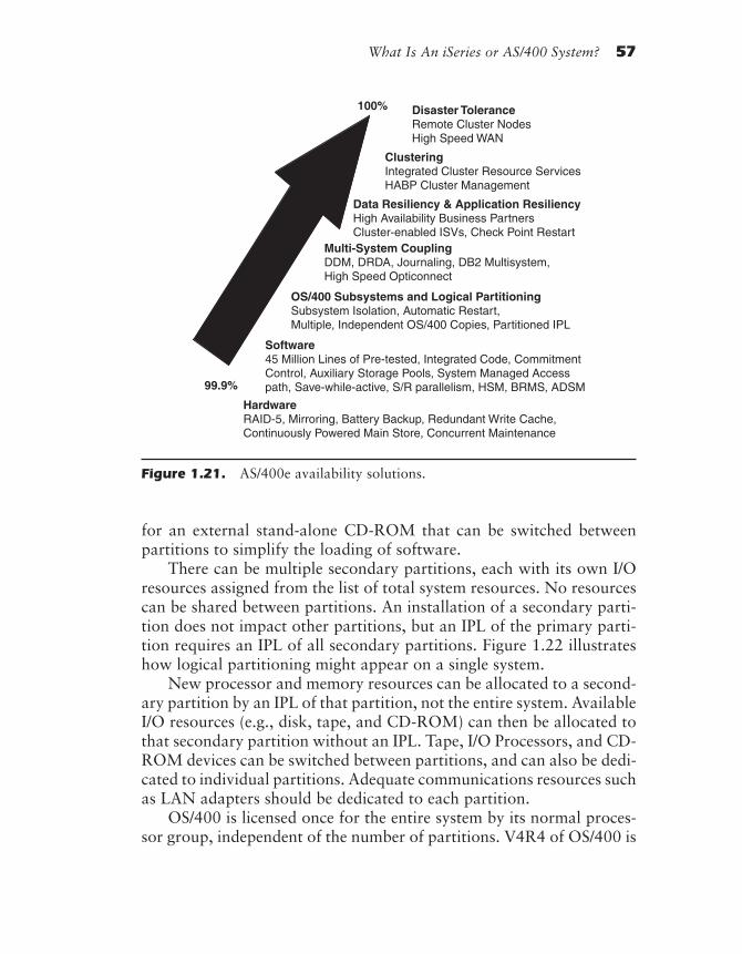
What Is An iSeries or AS/400 System? 57
for an external stand-alone CD-ROM that can be switched betweenpartitions to simplify the loading of software.
There can be multiple secondary partitions, each with its own I/Oresources assigned from the list of total system resources. No resourcescan be shared between partitions. An installation of a secondary parti-tion does not impact other partitions, but an IPL of the primary parti-tion requires an IPL of all secondary partitions. Figure 1.22 illustrateshow logical partitioning might appear on a single system.
New processor and memory resources can be allocated to a second-ary partition by an IPL of that partition, not the entire system. AvailableI/O resources (e.g., disk, tape, and CD-ROM) can then be allocated tothat secondary partition without an IPL. Tape, I/O Processors, and CD-ROM devices can be switched between partitions, and can also be dedi-cated to individual partitions. Adequate communications resources suchas LAN adapters should be dedicated to each partition.
OS/400 is licensed once for the entire system by its normal proces-sor group, independent of the number of partitions. V4R4 of OS/400 is
Figure 1.21. AS/400e availability solutions.
99.9%
HardwareRAID-5, Mirroring, Battery Backup, Redundant Write Cache,Continuously Powered Main Store, Concurrent Maintenance
Software45 Million Lines of Pre-tested, Integrated Code, CommitmentControl, Auxiliary Storage Pools, System Managed Accesspath, Save-while-active, S/R parallelism, HSM, BRMS, ADSM
OS/400 Subsystems and Logical PartitioningSubsystem Isolation, Automatic Restart,Multiple, Independent OS/400 Copies, Partitioned IPL
Multi-System CouplingDDM, DRDA, Journaling, DB2 Multisystem,High Speed Opticonnect
Data Resiliency & Application ResiliencyHigh Availability Business PartnersCluster-enabled ISVs, Check Point Restart
ClusteringIntegrated Cluster Resource ServicesHABP Cluster Management
Disaster ToleranceRemote Cluster NodesHigh Speed WAN
100%
rd-ch01.PMD 10/1/2002, 12:24 PM57
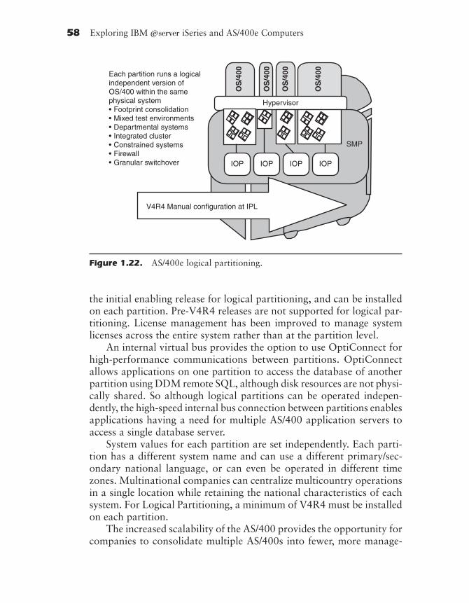
58 Exploring IBM ~ iSeries and AS/400e Computers
the initial enabling release for logical partitioning, and can be installedon each partition. Pre-V4R4 releases are not supported for logical par-titioning. License management has been improved to manage systemlicenses across the entire system rather than at the partition level.
An internal virtual bus provides the option to use OptiConnect forhigh-performance communications between partitions. OptiConnectallows applications on one partition to access the database of anotherpartition using DDM remote SQL, although disk resources are not physi-cally shared. So although logical partitions can be operated indepen-dently, the high-speed internal bus connection between partitions enablesapplications having a need for multiple AS/400 application servers toaccess a single database server.
System values for each partition are set independently. Each parti-tion has a different system name and can use a different primary/sec-ondary national language, or can even be operated in different timezones. Multinational companies can centralize multicountry operationsin a single location while retaining the national characteristics of eachsystem. For Logical Partitioning, a minimum of V4R4 must be installedon each partition.
The increased scalability of the AS/400 provides the opportunity forcompanies to consolidate multiple AS/400s into fewer, more manage-
Each partition runs a logicalindependent version ofOS/400 within the samephysical system• Footprint consolidation• Mixed test environments• Departmental systems• Integrated cluster• Constrained systems• Firewall• Granular switchover IOP IOP IOP IOP
V4R4 Manual configuration at IPL
Hypervisor
OS
/400
OS
/400
OS
/400
OS
/400
SMP
Figure 1.22. AS/400e logical partitioning.
rd-ch01.PMD 10/1/2002, 12:25 PM58

What Is An iSeries or AS/400 System? 59
able systems. Logical Partitioning (LPAR) in OS/400 enhances the roleof the AS/400 as a consolidated server. Logical partitioning providesboth the power and flexibility to address multiple systems requirementsin a single machine. Logical partitioning needs to be considered for en-vironments requiring server consolidation, business unit consolidation,mixed production and test environments, and integrated clusters.
Product Preview—LPAR Enhancements
It will be possible in the future to run multiple partitions on a singleprocessor. The current requirement that at least one processor must bededicated to each partition will no longer be true. Resources will becapable of reallocation dynamically between partitions with no IPL re-quired after the reallocation. Partitioning management will be managedusing Operations Navigator to simplify the management process.
Multisystem Coupling
Multiple AS/400 systems can be coupled using the OS/400 resourcesassociated with Distributed Data Management (DDM), DistributedRelational Database Architecture (DRDA), Journaling, DB2 Multisys-tem support for Symmetrical Multi-Processors, and high-speedOptiConnect.
Data Resiliency and Application Resiliency
Data resiliency and application resiliency are provided by the IBMhigh-availability business partners DataMirror, Vision Solutions, andLakeview Technology. Checkpoint restart is a capability included withinthe software provided by these business partners. Also included withinthe business partner provided software are cluster management, datareplication, and application availability tools.
Two types of cluster resource groups are supported, one for dataresiliency and one for application resiliency. Data resiliency providesthe capability to switch the point of access for a set of data over to abackup node that is maintaining an exact replica of that data. Resilientresources are object replicated to one or more nodes of a cluster. Appli-cation resilience provides the capability to switch an IP address (repre-
rd-ch01.PMD 10/1/2002, 12:25 PM59
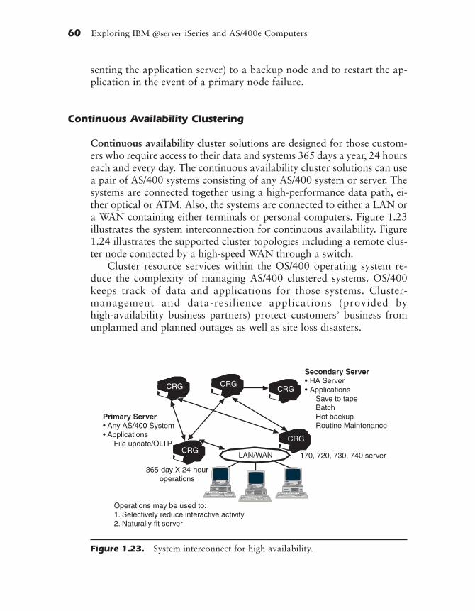
60 Exploring IBM ~ iSeries and AS/400e Computers
senting the application server) to a backup node and to restart the ap-plication in the event of a primary node failure.
Continuous Availability Clustering
Continuous availability cluster solutions are designed for those custom-ers who require access to their data and systems 365 days a year, 24 hourseach and every day. The continuous availability cluster solutions can usea pair of AS/400 systems consisting of any AS/400 system or server. Thesystems are connected together using a high-performance data path, ei-ther optical or ATM. Also, the systems are connected to either a LAN ora WAN containing either terminals or personal computers. Figure 1.23illustrates the system interconnection for continuous availability. Figure1.24 illustrates the supported cluster topologies including a remote clus-ter node connected by a high-speed WAN through a switch.
Cluster resource services within the OS/400 operating system re-duce the complexity of managing AS/400 clustered systems. OS/400keeps track of data and applications for those systems. Cluster-management and data-resilience applications (provided byhigh-availability business partners) protect customers’ business fromunplanned and planned outages as well as site loss disasters.
Figure 1.23. System interconnect for high availability.
rd-ch01.PMD 10/1/2002, 12:25 PM60

What Is An iSeries or AS/400 System? 61
Cluster resource services contain an open set of APIs providing clusterfacilities available to AS/400 application providers and customers toenhance application availability. These APIs allow the creation, con-figuration, and administration of the cluster. Systems are defined intothe cluster as cluster nodes. Communication interface addresses are de-fined to form the cluster node interconnection links.
Cluster resource services also provide low-level facilities such as heart-beat monitoring, reliable message delivery, switchover administration, anddistributed activities. The services are built on cluster topology and mes-saging functions, which keep track of each node in the cluster and ensurethat all nodes have consistent information about the state of cluster re-sources. Heartbeat monitoring ensures the active state of each node. Ifthe heartbeat for a node fails, the condition is reported and the clustercan automatically fail-over to the resilient resources on the backup node.
AS/400 clusters support up to 128 nodes (instances of OS/400), us-ing any combination of the existing OptiConnect, WAN, and LAN con-
LPAR
ATMWAN
Switch
730
740
640
HubTower
170
170
170 170
170
620
720
170 170
530
650Hub
Tower
Figure 1.24. Cluster topologies supported for AS/400.
rd-ch01.PMD 10/1/2002, 12:25 PM61

62 Exploring IBM ~ iSeries and AS/400e Computers
nectivity options to build the cluster. A single workstation (containingthe continuous-availability business partner cluster management appli-cation) manages all systems in the cluster. OptiConnect hardware is aconnectivity method for high- and midrange models. ATM provides ahigh-performance connection to remote systems in a cluster. Ethernetand Token-Ring LANs can be used to connect low-end AS/400 modelsinto a cluster.
Data resilience support for modern applications has been enhancedwith the introduction of Byte Stream File (BSF) replication. Businesspartner solutions provide real-time recording of changes to BSF datareplication to remote systems. Transfer of changes using remotejournaling protects in-flight data at the point of failure.
Disaster Tolerance
Disaster tolerance is provided by the support of remote cluster nodes asreplication points for resilient data. The remote cluster nodes can be offthe customer site, and may even use facilities of other businesses likeIBM to provide recovery mechanisms. High-Speed WAN facilities likeATM are used to support the remote cluster nodes. Disaster environ-ments include hurricanes, tornadoes, and floods, wherein the businessbecomes unable to utilize its local facilities for a period of time.
A 1998 Gartner Group study compared the availability of varioussystems. The only systems that ranked higher than the AS/400 wereclustered systems. The average NT server outages were forty times worsethan the AS/400.
Upgrades
There are two methods available for upgrading within the AS/400e se-ries product line: upgrading within a model and upgrading through asystem unit swap.
Upgrading within a Model
This method is used if the need is for more performance or input/output(I/O) device functionality and the current system is not using the maxi-mum performance features available within the specific AS/400 model.
rd-ch01.PMD 10/1/2002, 12:25 PM62
What Is An iSeries or AS/400 System? 63
These could be the processor, interactive processor feature, main stor-age size, attachable I/O device capability, or disk storage size. In thissituation, performance can be upgraded within a model by swappingprocessors, adding additional main storage, or adding disk storage oradditional IOPs without having to swap system units. In general, thesystem should be upgraded within the model until those maximums arereached. This method of growth is referred to as horizontal growth.
Upgrading through a System Unit Swap
Another way to upgrade within the AS/400 family is to replace the cur-rent AS/400 system unit with a more powerful model (e.g., you upgradea Model 820 to a Model 830 or 840 by changing the system unit). Thismethod is used if the current system is at its processor and storage maxi-mums, or if the number of users has increased beyond the capabilitiesof the current model. This method would also be used if there is a needfor application programs that run on newer RISC-based AS/400 modelsonly, or if you are upgrading from an older AS/400 model. This methodof growth is referred to as vertical growth.
Upgrading through Migration Towers
Upgrades to the AS/400 Models 820, 830, or 840 from 6XX/7XX/SXXmodels is performed by means of converting the system unit for thosemodels to a migration tower. The type of migration tower involved inthe conversion depends on the original model being upgraded. Figures1.25 and 1.26 illustrate this migration activity. In all cases, the existingI/O previously included in the system unit as well as the I/O attached tothe system unit through expansion towers remains in place and contin-ues to be used with the new model. New I/O devices are placed in thenew system unit, and any expansion towers required by the customerare supported by that model’s system unit.
Upgrades between Models
No upgrades between Models 6XX/SXX/7XX and 8XX servers may beaccomplished without exchanging the system unit. You can continue touse all the same workstations, modems, and so forth. Upgrades of CPUsfrom a Model 150, Model 170, Dedicated Server for Domino 170D,SB1, 4XX/5XX, or CISC to 8XX models are not supported. Upgrades
rd-ch01.PMD 10/1/2002, 12:25 PM63

64 Exploring IBM ~ iSeries and AS/400e Computers
Figure 1.25. The migration process for 6XX/SXX7/XX servers to 8XXservers.
Figure 1.26. I/O tower coexistence with previous I/O on 8XX servers.
Process● Leave I/O in place● Convert System Unit● Connect Migration Tower to 8xx
rd-ch01.PMD 10/1/2002, 12:25 PM64

What Is An iSeries or AS/400 System? 65
from these models will get a new serial number. Upgrades between the6XX/SXX/7XX servers and 8XX servers, including migration toweridentification, are illustrated in Appendix G. These upgrades will retainthe same serial number for the new models.
Appendix F identifies the recommended migration paths betweenolder AS/400 system/server models and the new system/server models.
Performance Overview
One important aspect of a computer system is its performance—that is,the speed at which the computer can perform work. The higher theperformance, the more work the computer can do. Many things—suchas the processor, main storage, disk storage, I/O bandwidth, and pro-gram design—affect the performance of a computer system. It is diffi-cult and often misleading to predict the overall performance of acomputer system by looking at selected specifications of the individualcomponents that make up the system. Although things such as disk unitseek times and raw processor speed (usually measured in millions ofinstructions per second, or MIPS) are important, they do not providethe whole picture in terms of overall system performance. In general,the higher the MIPS value, the better. The group of things that fit intothe category “more is better” include: number of processors, super sca-lar—number of execution units per processor, the presence or size of L1cache, the presence or size of L2 cache, the size of memory, and thenumber of buses. Some things fit into the category “faster is better,”including transfer rate (how fast information can be moved from cacheto the processor), transfer rate (how fast information can be movedfrom the memory to the processor), transfer rate (how fast informationcan be moved from the I/O subsystem to memory), link rate (the speedof the link or bus to I/O devices—disk), and switch rate (total rate ofmoving information between processors, memory, and I/O subsystems).The one area where “smaller is better” is pipeline depth—the numberof stages a machine instruction takes to execute. This becomes moreimportant when related to the frequency at which the processor per-forms task switching or logic switching as opposed to sequential pro-cessing. With a task switch, the pipeline is flushed and needs to be refilled.The bigger the pipeline, the longer it takes to feed instructions through
rd-ch01.PMD 10/1/2002, 12:25 PM65

66 Exploring IBM ~ iSeries and AS/400e Computers
the pipeline to feed the processor, and the longer the processor waits.Commercial applications tend to have a lot of task and logic switching.
In addition to these considerations, in the case of the AS/400e Seriescomputers, performance must be considered in relation to the environ-ment in which the computer system is executing. The AS/400 may oper-ate in a general-purpose (batch and interactive processing) environmentor in a client/server environment. What makes a computer function wellin one of these environments may be an inhibitor in the other environ-ment. (A computer that has been tuned for the client/server environ-ment will perform weakly in an interactive environment, and vice versa.)As a result, different methodologies are used to measure computer per-formance for those different environments.
When choosing a multiuser computer system, it is important to un-derstand that the maximum number of active users is different from themaximum number of workstations that can be attached to a system.History has shown that when the active number of users is greater than40 percent of the maximum number of workstations allowed, there is astrong probability that some of the users will start to experience a de-crease in response. The maximum number of users is not a system con-figuration limitation, but rather a system performance limitation forthe benchmark used. Therefore, when some of the user population in-cludes only occasional users, it is normally desirable to put more work-stations on a system than can simultaneously supported.
The response time of a computer system is at least as important asthroughput. Users’ satisfaction and productivity can be drastically af-fected by a computer’s sluggish response after the user hits the Enterkey. As was mentioned earlier, response time is related to the workloadon the computer system. This is not intended to imply that everyworkload will see subsecond response time.
Benchmark Testing Overview
Benchmark testing has evolved as the best way to compare the overallperformance of different computers. Benchmark testing involves load-ing the computer system with various programs designed to simulate aworkload and then measuring how the system behaves under the load.Through this benchmark testing, all elements of the computer systemcome into play, and the overall performance of selected computer sys-tems can be meaningfully compared.
rd-ch01.PMD 10/1/2002, 12:25 PM66

What Is An iSeries or AS/400 System? 67
To perform benchmark testing, the test group must make assump-tions about the kind of work being done and the behavior of the usersat each workstation. For this reason, the performance measurementsderived from a benchmark may vary significantly from what users willget if their business environment does not match the set of test assump-tions. For example, word-processing users typically load a system downmore heavily than users performing business transactions. Therefore, asystem with heavy word-processing activity will usually not be able tosupport as many users as a system performing order entry.
However, because all assumptions are the same for all computersincluded in the benchmark testing, it is possible to get a good idea of therelative performance of tested computer systems. IBM has conductedbenchmark testing on AS/400 systems using the CPW benchmark, whichis designed to simulate a typical business workload (e.g., order entry,accounts payable, and accounts receivable).
When IBM’s AS/400 group benchmarks a system, the benchmark isagainst criteria that measure how that system is intended to be used.The general-purpose systems, like the previous Models 600 and 650,are benchmarked against their ability to support interactive users. Inthis context, whatever system capacity is not being used for interactiveusers is available for performing other work such as client/server–basedfile serving or print serving. Other systems, like the server-based sys-tems, are intended to provide the majority of their capabilities for thebatch mode server-based functions such as printing, file serving, com-munications serving, and so forth. They are benchmarked againstcriteria that measure how well the systems perform in that environ-ment.
The AS/400e solutions packaging preload environments are mea-sured against criteria that combine the need to get a larger number ofinteractive users applying a workload while still allowing a significantclient/server workload. The AS/400e solutions packaging preload envi-ronments expect to perform their function with this increased interac-tive workload while supporting a limited set of business partnerapplications.
The chart shown in Figure 1.27 illustrates the expected performancefor the described benchmark environments for the Models 8XX and270 CPUs. If this chart were compared to the previous Models 170 and7XX CPU charts, the difference would occur after the point where theinteractive performance reached its maximum capability. With the newCPUs, the available client/server performance stays fixed after the inter-
rd-ch01.PMD 10/1/2002, 12:25 PM67

68 Exploring IBM ~ iSeries and AS/400e Computers
active performance has peaked, and continuing demands on interactiveperformance cause the interactive performance to decrease. There is nointerference from system overhead caused by excess interactive workloadfor any or all client/server workloads.
As an example, for the AS/400e 840-#2418 processor, total proces-sor CPW rating is 10,000. (If the interactive feature #1544 is present,the maximum interactive performance is 2,000 CPW, and a minimumclient/server performance capability of 8,000 CPW is available.) If, atany point in time, only 50 percent of the interactive performance isbeing used, then 9,000 CPW is available for client/server usage. De-pending on how the job priorities are set, a big difference exists in theresults.
8XX Model Priorities
The default for the Model 8XX processors when interactive cards arepresent is that when the interactive workload exceeds 115 percent ofthe design point, the interactive activity begins to slow down, and theserver workload is unaffected.
Model 8xx and Model 270 CPUDistribution vs. Interactive Utilization
Percent of Interactive Capacity Used
0
0
20
40
60
80
100
Knee
Max
Available forClient/Server
Client/Server
InteractiveAva
ilabl
e C
PU
Figure 1.27. Interactive Performance Model—What’s This?
rd-ch01.PMD 10/1/2002, 12:25 PM68
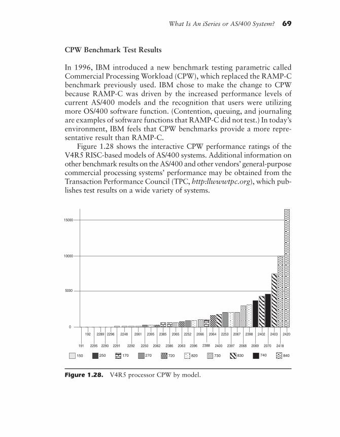
What Is An iSeries or AS/400 System? 69
CPW Benchmark Test Results
In 1996, IBM introduced a new benchmark testing parametric calledCommercial Processing Workload (CPW), which replaced the RAMP-Cbenchmark previously used. IBM chose to make the change to CPWbecause RAMP-C was driven by the increased performance levels ofcurrent AS/400 models and the recognition that users were utilizingmore OS/400 software function. (Contention, queuing, and journalingare examples of software functions that RAMP-C did not test.) In today’senvironment, IBM feels that CPW benchmarks provide a more repre-sentative result than RAMP-C.
Figure 1.28 shows the interactive CPW performance ratings of theV4R5 RISC-based models of AS/400 systems. Additional information onother benchmark results on the AS/400 and other vendors’ general-purposecommercial processing systems’ performance may be obtained from theTransaction Performance Council (TPC, http:llwwwtpc.org), which pub-lishes test results on a wide variety of systems.
191
192
0
5000
10000
15000
2420
2418
2403
2070
2402
20692068
23982067
2397
2253
2400
2064
2388
2066
2396
2252
2063
2065
2386
2385
2062
2395
2250
2061
22922291
22482296
2290
2289
2295
270150 730 840250 720170 830820 740
Figure 1.28. V4R5 processor CPW by model.
rd-ch01.PMD 10/1/2002, 12:25 PM69
70 Exploring IBM ~ iSeries and AS/400e Computers
Symmetrical Multi-Processing (SMP)
Some of the AS/400e models use Symmetrical Multi-Processing (SMP),meaning that they use more than one processor in a single system. (Thediscussion “Hardware Architecture Overview” later in this chapter con-tains more on how multiple processors achieve this performance increase.)With SMP, the performance rating increases with each new processoradded. For example, if you compare a single processor system to an SMPsystem with two processors of identical power, you get a performanceincrease of about 70 percent. You don’t get a 100 percent improvementbecause the two system processors must spend some of their processingpower coordinating activities with one another. They must also share thesame main storage, I/O bus (or buses), disk storage, and so on. For thesereasons, adding a second system processor does not double the perfor-mance of the system; however, SMP configurations do allow significantperformance improvements. Figure 1.28 shows the performance advan-tage afforded by the use of two-, four-, and eight-way processors in theModel 730, along with eight-way (#2240) and twelve-way (#2243) pro-cessors in the Model 740 SMP configurations.
Server Performance
Client/Server Labs measures server performance on systems for manycompanies, using a benchmark suite specially tailored for servers. Theserver environment evolved as a result of two nearly coincidental events:(1) the personal computer (PC) penetration into the generalized busi-ness world and (2) the natural desire to share the information containedon those PCs. The PC put the power of computers into the hands ofeach critical individual within a business.
The need to share the results on one PC with the users on severalPCs resulted in the definition of the local area network (LAN). An ex-ample of an application across a LAN would be this: If one secretary ata business location reserved a conference room for 1:00 p.m. on Tues-day, other secretaries would see that the conference room was reserved(including when, and by whom). As in this example, a LAN should beused to connect together groups of users with some common interest.The first LAN to be defined was Ethernet (which eventually becameIEEE 803.2), followed later by the token ring (which became IEEE 803.5).LAN definitions, speeds, and protocols that could not talk to each other
rd-ch01.PMD 10/1/2002, 12:25 PM70

What Is An iSeries or AS/400 System? 71
proliferated until finally the distributed computing environment emerged,settling upon TCP/ IP and APPC as the LAN access method and man-agement structure.
Another problem of networking only PCs is that if one user wants aspecific piece of information and the PC that has that information isturned off at the time the information is needed, the information cannotbe accessed. Also, since PCs have limited disk storage space, individualusers were asking why they should spend money and time creating arepository for data that, once created, might be of no further interest.Finally, the question of controlling access to the information on thenetwork was begging for an answer because of privacy (andneed-to-know) issues.
An answer that evolved was the client/server relationship, in whichthe PCs were the clients and the server was a large centralized reposi-tory of information. In this environment, the client requested either pro-grams or data from the server, which checked the client’s authorizationto receive that information and sent the data to the client. The clientthen processed the data and sent the results back to the server reposi-tory for long-term storage. In order to check the authorization, find theprograms and data, and provide enough storage repository to be useful,the server required the processing characteristics of the client. In fact, inthe case of certain long-running applications, it would be preferable toexecute the application at the server and send only the results of theapplication to the client, who could then decide whether the data gener-ated should reside on the server or at the client. Since the long-runningapplication executed on the server, this freed up the client resources forexecution of short-running applications during the long application’sexecution time.
It follows, then, that minimizing paths in the server for APPC andTCP/IP, and minimizing database search structures (via good search al-gorithms, improved base structures, some capability for parallel I/Oprocessing, efficient file serving, and efficient batch-processing capabil-ity) are the characteristics of a good server. The performance of theserver models is shown in Figure 1.28, with the tallest column showingthe server batch-processing performance at Version 4 Release 4 andVersion 4 Release 5. It is no longer necessary to limit the configurationand the available application set to provide improved interactive per-formance as was done for the custom mixed-mode S20-ISV, S30-ISV,and S40-ISV models.
rd-ch01.PMD 10/1/2002, 12:25 PM71
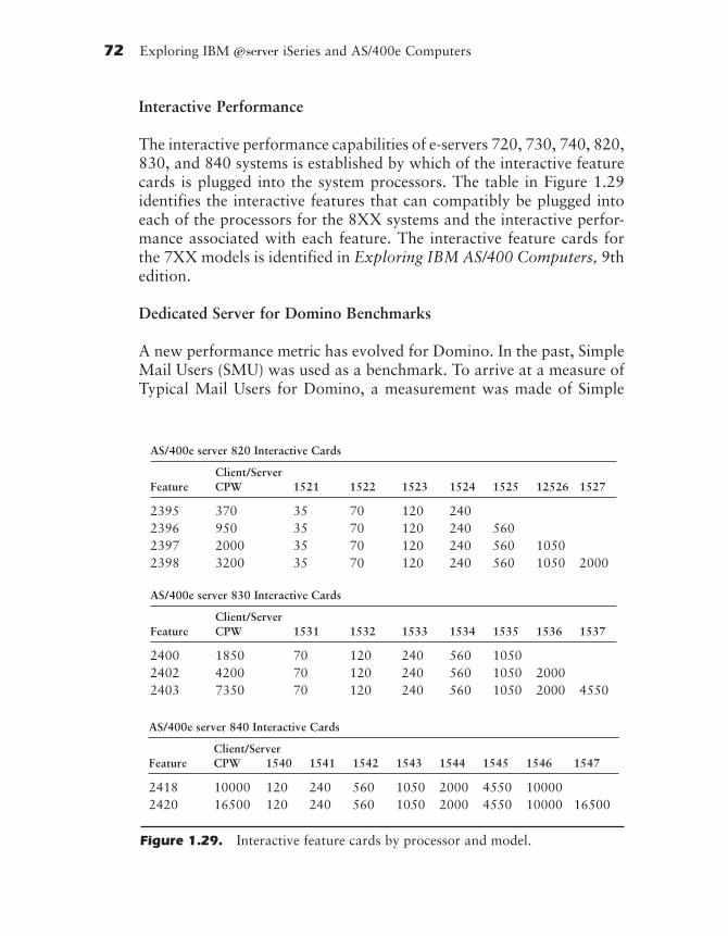
72 Exploring IBM ~ iSeries and AS/400e Computers
Interactive Performance
The interactive performance capabilities of e-servers 720, 730, 740, 820,830, and 840 systems is established by which of the interactive featurecards is plugged into the system processors. The table in Figure 1.29identifies the interactive features that can compatibly be plugged intoeach of the processors for the 8XX systems and the interactive perfor-mance associated with each feature. The interactive feature cards forthe 7XX models is identified in Exploring IBM AS/400 Computers, 9thedition.
Dedicated Server for Domino Benchmarks
A new performance metric has evolved for Domino. In the past, SimpleMail Users (SMU) was used as a benchmark. To arrive at a measure ofTypical Mail Users for Domino, a measurement was made of Simple
AS/400e server 820 Interactive Cards
Client/ServerFeature CPW 1521 1522 1523 1524 1525 12526 1527
2395 370 35 70 120 2402396 950 35 70 120 240 5602397 2000 35 70 120 240 560 10502398 3200 35 70 120 240 560 1050 2000
AS/400e server 830 Interactive Cards
Client/ServerFeature CPW 1531 1532 1533 1534 1535 1536 1537
2400 1850 70 120 240 560 10502402 4200 70 120 240 560 1050 20002403 7350 70 120 240 560 1050 2000 4550
AS/400e server 840 Interactive Cards
Client/ServerFeature CPW 1540 1541 1542 1543 1544 1545 1546 1547
2418 10000 120 240 560 1050 2000 4550 100002420 16500 120 240 560 1050 2000 4550 10000 16500
Figure 1.29. Interactive feature cards by processor and model.
rd-ch01.PMD 10/1/2002, 12:25 PM72
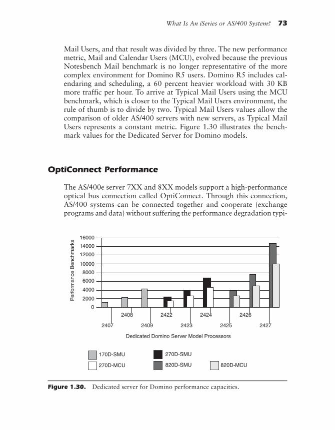
What Is An iSeries or AS/400 System? 73
Mail Users, and that result was divided by three. The new performancemetric, Mail and Calendar Users (MCU), evolved because the previousNotesbench Mail benchmark is no longer representative of the morecomplex environment for Domino R5 users. Domino R5 includes cal-endaring and scheduling, a 60 percent heavier workload with 30 KBmore traffic per hour. To arrive at Typical Mail Users using the MCUbenchmark, which is closer to the Typical Mail Users environment, therule of thumb is to divide by two. Typical Mail Users values allow thecomparison of older AS/400 servers with new servers, as Typical MailUsers represents a constant metric. Figure 1.30 illustrates the bench-mark values for the Dedicated Server for Domino models.
OptiConnect Performance
The AS/400e server 7XX and 8XX models support a high-performanceoptical bus connection called OptiConnect. Through this connection,AS/400 systems can be connected together and cooperate (exchangeprograms and data) without suffering the performance degradation typi-
Dedicated Domino Server Model Processors
2407
2408
2409
2422
2423
2424
2425
2426
2427
0
2000
4000
6000
8000
10000
12000
14000
16000
Per
form
ance
Ben
chm
arks
170D-SMU
270D-MCU
270D-SMU
820D-SMU 820D-MCU
Figure 1.30. Dedicated server for Domino performance capacities.
rd-ch01.PMD 10/1/2002, 12:25 PM73

74 Exploring IBM ~ iSeries and AS/400e Computers
cally associated with system interconnection via other methods (e.g.,TCP/IP, Ethernet, or token-ring networks).
Measured performance capacity increases (1.5 to 1.7 times the per-formance of a single system, depending upon application efficiency) haveresulted from connecting two AS/400 systems together via OptiConnect.Currently, up to thirty-two AS/400 systems can be connected viaOptiConnect to provide loosely coupled distributed computing.
Loosely coupled computing is an environment in which data and pro-grams are exchanged between computers over a serial communications line,which from a hardware aspect of the systems is the only thing shared. Thecoupling is referred to as “loose” because the potential processing occurringin the system (from which the information is being moved) is significantduring the period of the transfer, and because of the resulting problems in-volved in keeping the information in the sharing systems synchronized.
A Closer Look
Many elements provide the functions and performance of IBM AS/400computers. This is perhaps the appropriate place to mention that manyof the concepts used in the AS/400 system were built on those of IBM’sSystem/38 computer. This fact is a testimonial to the rich function andgrowth capability built into the original System/38!
The remainder of this chapter provides a closer look at the follow-ing aspects of the IBM AS/400 systems: hardware architecture, cluster-ing technology, OptiConnect technology, main and auxiliary storage,packaging, and the fiber optic bus.
Hardware Architecture Overview
The underlying arrangement and interconnection of a computer system’selectrical components is called its hardware architecture. This architec-ture is the fundamental structure upon which all system functions arebuilt and has the largest effect on how the computer system will behave.A basic understanding of the AS/400 system architecture (Figure 1.31)makes it possible to compare AS/400 computers with other systems andto understand important aspects of system performance and capacity.
rd-ch01.PMD 10/1/2002, 12:25 PM74
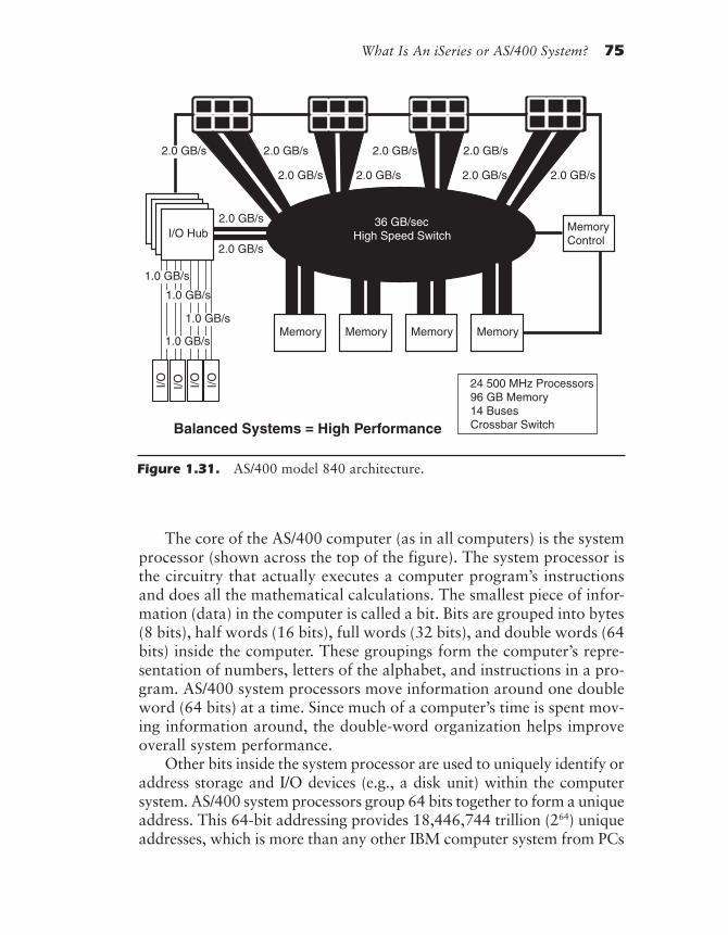
What Is An iSeries or AS/400 System? 75
The core of the AS/400 computer (as in all computers) is the systemprocessor (shown across the top of the figure). The system processor isthe circuitry that actually executes a computer program’s instructionsand does all the mathematical calculations. The smallest piece of infor-mation (data) in the computer is called a bit. Bits are grouped into bytes(8 bits), half words (16 bits), full words (32 bits), and double words (64bits) inside the computer. These groupings form the computer’s repre-sentation of numbers, letters of the alphabet, and instructions in a pro-gram. AS/400 system processors move information around one doubleword (64 bits) at a time. Since much of a computer’s time is spent mov-ing information around, the double-word organization helps improveoverall system performance.
Other bits inside the system processor are used to uniquely identify oraddress storage and I/O devices (e.g., a disk unit) within the computersystem. AS/400 system processors group 64 bits together to form a uniqueaddress. This 64-bit addressing provides 18,446,744 trillion (264) uniqueaddresses, which is more than any other IBM computer system from PCs
Memory
MemoryControl
36 GB/secHigh Speed Switch
2.0 GB/s 2.0 GB/s 2.0 GB/s
2.0 GB/s 2.0 GB/s 2.0 GB/s 2.0 GB/s
2.0 GB/sI/O Hub
2.0 GB/s
Memory MemoryMemory
I/O I/O I/OI/O
1.0 GB/s
1.0 GB/s
1.0 GB/s
1.0 GB/s
Balanced Systems = High Performance
24 500 MHz Processors96 GB Memory14 BusesCrossbar Switch
2.0 GB/s
Figure 1.31. AS/400 model 840 architecture.
rd-ch01.PMD 10/1/2002, 12:25 PM75
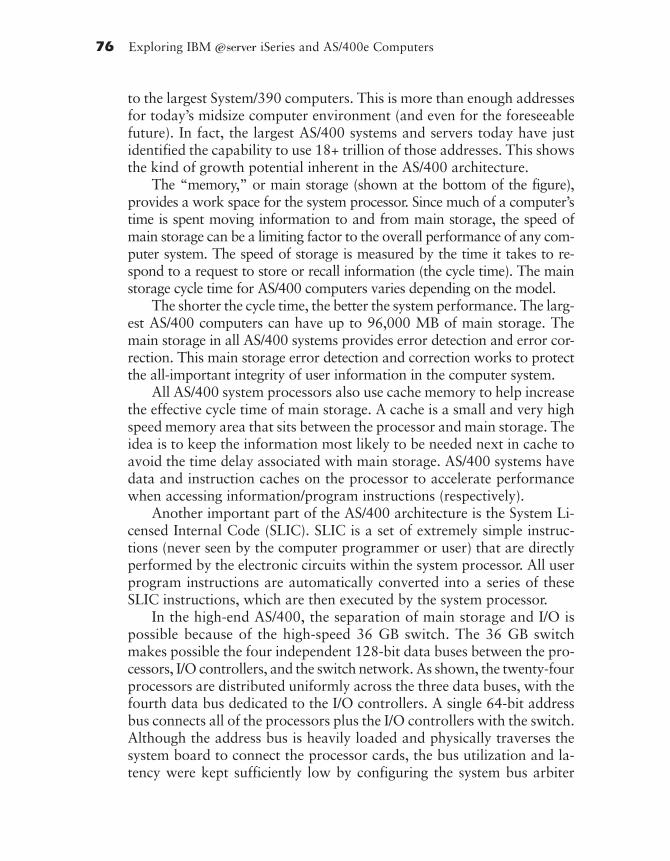
76 Exploring IBM ~ iSeries and AS/400e Computers
to the largest System/390 computers. This is more than enough addressesfor today’s midsize computer environment (and even for the foreseeablefuture). In fact, the largest AS/400 systems and servers today have justidentified the capability to use 18+ trillion of those addresses. This showsthe kind of growth potential inherent in the AS/400 architecture.
The “memory,” or main storage (shown at the bottom of the figure),provides a work space for the system processor. Since much of a computer’stime is spent moving information to and from main storage, the speed ofmain storage can be a limiting factor to the overall performance of any com-puter system. The speed of storage is measured by the time it takes to re-spond to a request to store or recall information (the cycle time). The mainstorage cycle time for AS/400 computers varies depending on the model.
The shorter the cycle time, the better the system performance. The larg-est AS/400 computers can have up to 96,000 MB of main storage. Themain storage in all AS/400 systems provides error detection and error cor-rection. This main storage error detection and correction works to protectthe all-important integrity of user information in the computer system.
All AS/400 system processors also use cache memory to help increasethe effective cycle time of main storage. A cache is a small and very highspeed memory area that sits between the processor and main storage. Theidea is to keep the information most likely to be needed next in cache toavoid the time delay associated with main storage. AS/400 systems havedata and instruction caches on the processor to accelerate performancewhen accessing information/program instructions (respectively).
Another important part of the AS/400 architecture is the System Li-censed Internal Code (SLIC). SLIC is a set of extremely simple instruc-tions (never seen by the computer programmer or user) that are directlyperformed by the electronic circuits within the system processor. All userprogram instructions are automatically converted into a series of theseSLIC instructions, which are then executed by the system processor.
In the high-end AS/400, the separation of main storage and I/O ispossible because of the high-speed 36 GB switch. The 36 GB switchmakes possible the four independent 128-bit data buses between the pro-cessors, I/O controllers, and the switch network. As shown, the twenty-fourprocessors are distributed uniformly across the three data buses, with thefourth data bus dedicated to the I/O controllers. A single 64-bit addressbus connects all of the processors plus the I/O controllers with the switch.Although the address bus is heavily loaded and physically traverses thesystem board to connect the processor cards, the bus utilization and la-tency were kept sufficiently low by configuring the system bus arbiter
rd-ch01.PMD 10/1/2002, 12:25 PM76

What Is An iSeries or AS/400 System? 77
located within the switch to allow only one address for every two datacycles. The I/O is driven from an HSL bus (the HSL bus is anultra-high-speed serial interface), a copper bus limited to fifteen feet inlength for a single segment, having a bandwidth of 10 GB/sec. The cop-per bus connects to at least one I/O tower, which can be populated withdisk units, tape units, and I/O interface cards. The main storage bus ispartitioned into multiple buses, each of which is supported by a separatestorage control chip (STG/CTL) that manages the main storage accessesand up to 0.5 MB of intermediate-level cache. This multiple-memory busarchitecture helps improve the performance of these systems.
The I/O processors (shown at the bottom of the figure) are respon-sible for managing any devices attached to the AS/400 system. Each ofthese specialized processors has independent responsibilities and per-forms tasks in coordination with the system processor. A computer thathas multiple processors working together with the system processor likethis has a multiprocessor architecture. The advantage of having mul-tiple processors performing work simultaneously is simply that morework can be done in a given period of time. For example, the worksta-tion I/O processor manages the detailed processing associated with themultiple terminals and printers attached to the system, allowing thesystem processor to concentrate on doing more productive work for theuser. The same is true of the other specialized I/O processors such as thestorage I/O processor, which manages disk, diskette, and tape devicesattached to the AS/400 system.
The I/O processors communicate with the system processor over an I/Obus (called the PCI bus), a group of wires that carry information very quicklyfrom one area to another inside the computer system. As indicated in the fig-ure, some AS/400 systems have a single I/O bus, whereas others have multipleI/O buses. Because only one information transfer can occur on any one bus atany one time, systems with multiple buses have the advantage of allowingoverlapping transfers between I/O processors and the system processor or mainstorage. Therefore, multiple buses contribute to the overall system performanceadvantages of larger AS/400 systems. The PCI I/O buses in the 8XX modelsprovide an I/O bandwidth of greater than 10 GB for the movement of data andinstructions between the I/O devices and the processor/memory complex.
Various controllers and adapters plug into physical slots in each ofthe packages used to provide electrical connections to the bus. In addi-tion to I/O processors, a service processor (shown in the upper right ofthe figure) is built into every AS/400. It is responsible for starting thesystem and constantly monitoring the health of the entire computer. It
rd-ch01.PMD 10/1/2002, 12:25 PM77

78 Exploring IBM ~ iSeries and AS/400e Computers
interacts with the system operator through the control panel and helpswith such things as system fault isolation, error detection, and errorreporting. It is the equivalent of having a built-in service person whowatches over things with relentless consistency.
All AS/400 systems employ a multiprocessor architecture in thatthey have a system processor and multiple specialized processors (e.g.,workstation and I/O processors) to handle specific tasks. However, largerAS/400 models (e.g., Models 170, 720, 730, 740, 820, 830, and 840)employ multiple system processors to cooperatively execute a single copyof the operating system (OS/400), thus appearing to be a single largeprocessor. This multiple system processor architecture is called the N-waymultiprocessor architecture (where N is replaced by the number of pro-cessors), also referred to as the Symmetric Multi- Processor (SMP) ar-chitecture.
Figure 1.32 shows how N-way models are organized. (Note: Allsystem processors share the same I/O buses, I/O processors, and mainstorage.) Symmetric Multi-Processors process in parallel, sharing a tasklist. Each processor in a symmetric multiprocessor set has its own dataand instruction cache, and its own virtual storage view of the system. Inthe case of a query, each processor in the SMP group will process inparallel against a segment of disk storage to resolve the query.
Clustering Technology
The AS/400 leverages the clustering capability both to providehigh-availability systems and to allow for horizontal growth of theAS/400 systems. The following paragraphs discuss the performance andconnection characteristics provided by the OptiConnect capability forhorizontal growth. Of course, these characteristics apply also in thehigh-availability connection for resilient data and resilient applications.
What Is OptiConnect/400?
OptiConnect/400 is the system-to-system interconnection fabric that al-lows distributed functions and applications to operate at high speed. Itcan be used to form a high-performance, multisystem, loosely coupledcluster.
Two things differentiate OptiConnect from traditionalcommunications-based distributed operations. The first is a system bus
rd-ch01.PMD 10/1/2002, 12:25 PM78
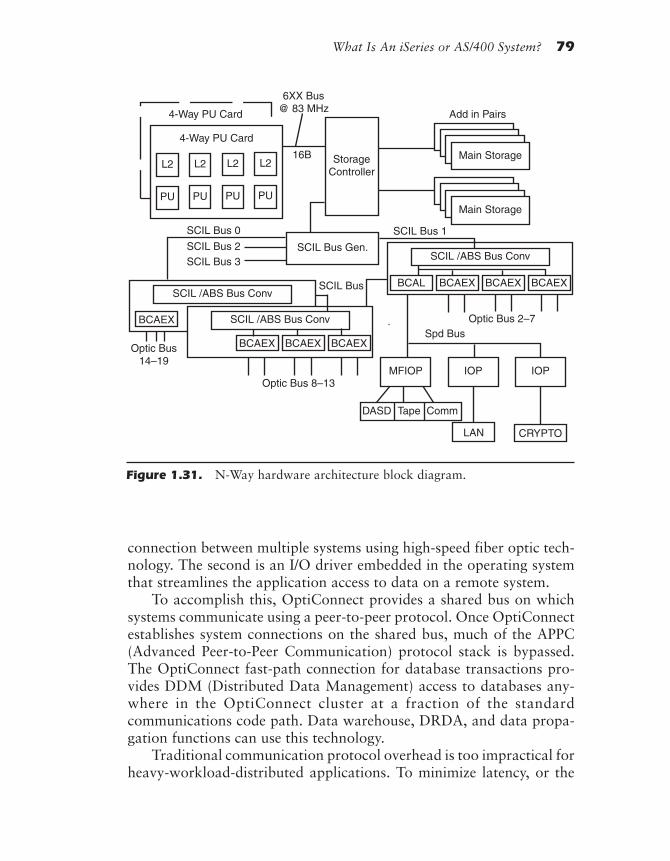
What Is An iSeries or AS/400 System? 79
connection between multiple systems using high-speed fiber optic tech-nology. The second is an I/O driver embedded in the operating systemthat streamlines the application access to data on a remote system.
To accomplish this, OptiConnect provides a shared bus on whichsystems communicate using a peer-to-peer protocol. Once OptiConnectestablishes system connections on the shared bus, much of the APPC(Advanced Peer-to-Peer Communication) protocol stack is bypassed.The OptiConnect fast-path connection for database transactions pro-vides DDM (Distributed Data Management) access to databases any-where in the OptiConnect cluster at a fraction of the standardcommunications code path. Data warehouse, DRDA, and data propa-gation functions can use this technology.
Traditional communication protocol overhead is too impractical forheavy-workload-distributed applications. To minimize latency, or the
4-Way PU Card
4-Way PU Card
L2
PU
L2
PU
L2
PU
L2
PU
6XX Bus@ 83 MHz
StorageController
Main Storage
Main Storage
Add in Pairs
16B
SCIL Bus Gen.
SCIL Bus 1
Optic Bus 2–7Spd Bus
MFIOP IOP IOP
DASD Tape Comm
CRYPTOLAN
SCIL /ABS Bus Conv
BCAEXBCAL BCAEX BCAEX
SCIL /ABS Bus Conv
BCAEX BCAEX BCAEX
SCIL /ABS Bus Conv
BCAEX
SCIL Bus 0
SCIL Bus 2SCIL Bus 3
SCIL Bus
Optic Bus14–19
Optic Bus 8–13
Figure 1.31. N-Way hardware architecture block diagram.
rd-ch01.PMD 10/1/2002, 12:25 PM79
80 Exploring IBM ~ iSeries and AS/400e Computers
time it takes to send a message and receive a response, the protocolchosen must be efficient in the number of code steps required. To maxi-mize bandwidth, or the amount of data that can be transferred in a unitof time, high-performance hardware must be used. The OptiConnectchannel is very efficient and is the best solution for both latency andbandwidth. The length of the cable affects how low latency can get. Asdistance increases, the speed of light becomes a limiting factor for agiven bandwidth. OptiConnect is limited to 500 meters over the 1,063Mbps (megabits per second) used on RISC models and 2 kilometersover the 220 Mbps link supported on CISC models.
OptiConnect/400–Enabled Functions
An OptiConnect cluster can consist of up to fourteen systems with fullsystem-to-system connectivity and up to thirty-two systems in complexstructures where all satellite systems must communicate with one ortwo hub systems. Figure 1.33 illustrates the clustering of three systemsthrough an expansion unit hub.
The OptiConnect for OS/400 software provides a streamlined com-munications path across the dedicated system buses. Together with thehardware, the following functions can utilize the high-speed system-buslevel connections between AS/400 systems:
• All Distributed Data Management (DDM) operations for sup-ported object types can run across OptiConnect, including datafiles, data areas, and data queues.
• All Structured Query Language (SQL) support provided byDRDA will run across OptiConnect, including distributed unitof work and remote unit of work.
• DB2 Multisystem with its DB2/400 support for multinode fileswill run across OptiConnect, providing data warehouse func-tions of Query/400 support and two-phase commit.
• ObjectConnect/400 will operate over OptiConnect to providehigh-speed system-to-system save/restore functions.
• Standard APPC conversations are available over OptiConnect withan OptiConnect communication controller. This allows for System
rd-ch01.PMD 10/1/2002, 12:25 PM80
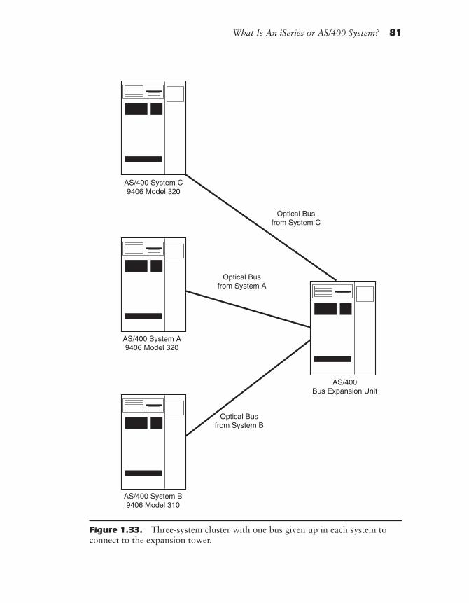
What Is An iSeries or AS/400 System? 81
AS/400 System B9406 Model 310
AS/400 System C9406 Model 320
AS/400 System A9406 Model 320
Optical Busfrom System C
Optical Busfrom System A
Optical Busfrom System B
AS/400Bus Expansion Unit
Figure 1.33. Three-system cluster with one bus given up in each system toconnect to the expansion tower.
rd-ch01.PMD 10/1/2002, 12:25 PM81

82 Exploring IBM ~ iSeries and AS/400e Computers
Network Architecture Distribution Services (SNADS), display sta-tion passthrough, network printer passthrough, and other functions.
• OptiConnect has an Application Program Interface (API) towhich business partner software packages can code.
OptiMover for OS/400 is a special, low-cost PRPQ version ofOptiConnect for OS/400 software. It enables non-DDM functions toutilize the OptiConnect high-speed link, allowing system-bus-level con-nections between AS/400 systems. “PRPQ” stands for ProgrammingRequest per Quote. Business-partner packages written to these APIsallow customers to take advantage of this lower-priced option.
OptiConnect/400 Environment
There are two primary uses for the OptiConnect technology. Horizon-tal growth is the traditional and most popular use. Separating databaseoperations from applications workload allows multiple systems to op-erate as a cluster to grow computing power beyond what a single sys-tem can provide. It is important to understand that not all applicationsare conducive to this type of workload distribution. The horizontalgrowth/scalability is dependent on the database I/O intensity. The bestimplementation is the separation of the interactive application from thecorresponding data while maintaining the batch application on the samesystem as the batch data. Techniques are available that transparentlymanage the batch job submission to the database server system.
The second use for OptiConnect technology is high availability. Whenused in conjunction with business-partner applications such as thoseoffered by Lakeview Technology and Vision Solutions, efficienthigh-availability solutions can be achieved. The OptiConnect technol-ogy provides the most efficient use of CPU resources to allow fast repli-cation of data between systems.
Main Storage
The “memory,” or main storage, is the set of electronic circuits withinan AS/400 system that provides a “workspace” for the system proces-sor. Data and programming instructions are moved from disk storageto main storage for the programs and the processing of data. After ex-
rd-ch01.PMD 10/1/2002, 12:25 PM82
What Is An iSeries or AS/400 System? 83
ecution or processing, modified data are moved back to main storageand kept there until no longer needed. At that point, the data are typi-cally written back to disk storage for safekeeping.
AS/400 systems spend much time moving information between thesystem processor and main storage. There are two major reasons thatthis is so. First, all programs currently being executed by the systemprocessor reside in main storage. Therefore, the system processor must(at some point) retrieve every instruction from main storage. Second,main storage holds the data to be acted on by the system processor.Since the information traffic between the system processor and mainstorage is heavy, the speed of main storage is important to overall sys-tem performance. That is why high-speed cache memory, which increasesthe effective speed of main storage, is included in the system design.
As we have seen, every main storage location in AS/400 main storageconsists of sixty-four pieces of information, or bits. All information in mainstorage is encoded using these 64-bit groupings, called double words. In ad-dition to the 64 bits of information, each word in main storage has severaladditional bits (called check bits) that are generated based on the value ofthat particular 64-bit word. In the event that one or two bits of the 64-bitwords is somehow corrupted, the check bits notify the AS/ 400 computerthat the error exists. If only one bit of the 64 bits is corrupted, as is usually thecase, the check bits actually restore the corrupted bit and correct the error.This main storage error detection and correction works to protect theall-important integrity of user information in the computer system.
Storage Management
The methods used within a computer system to manage main storageand disk storage, called the computer’s storage management, are funda-mental to the capabilities of the computer. Understanding the basics ofstorage management provides insight into one of the unique features ofAS/400 computers compared with traditional computer systems.
Figure 1.34 shows conceptually what the storage in AS/400 comput-ers looks like. All programs and information currently being used by thecomputer system must be contained in main storage, which resides insidethe computer’s system unit. Main storage is relatively expensive and re-sponds at very high speeds (compared to disk storage) when called on toprovide or store information. Because main storage loses all informationwhen the computer system is turned off, it is called volatile storage.
rd-ch01.PMD 10/1/2002, 12:25 PM83

84 Exploring IBM ~ iSeries and AS/400e Computers
Disk storage is less expensive but cannot provide or store informa-tion as quickly as main storage. Disk storage is said to be nonvolatilebecause it does not lose its information when the power is turned off (orlost due to a power failure). As a result of this nonvolatility and rela-tively low cost, disk storage is commonly used to hold all informationthat must be readily available to the computer. Disk storage may resideeither inside the system unit or inside a separate box cabled to the sys-tem unit (as depicted in the figure).
When the AS/400 computer is first turned on, information vital toan orderly startup and smooth operation is automatically copied fromthe disk to main storage. Once normal system operation is established,users can begin to do their work. During the course of this work, userswill start various computer programs. As each program is started, it iscopied from the disk to main storage and then executed. Depending onthe work being done, the computer programs manipulate various setsof data that are also loaded from the disk as needed. It does not takelong to realize that the main storage in a computer can quickly becomefilled up with programs and data as the system is called upon to domore and more work.
In the earlier days of computing, the main storage size limited theamount of work a computer could manage at any one time. This limita-tion capped the size of programs, the number of programs that could berun concurrently, the number of users that could share the system, and soon. In modern computers a technique called virtual storage (discussedmore fully in the next section) alleviates the need to squeeze all activeprograms and data into main storage. In computers that support virtualstorage, the computer basically “fakes out” the computer programs andappears to have much more main storage than it actually has. (TheAS/400 allows a virtual storage size of 18 million terabytes). Virtual stor-
MainMemory
DiskStorage
Figure 1.34. AS/400 main storage and fixed disk storage.
rd-ch01.PMD 10/1/2002, 12:25 PM84

What Is An iSeries or AS/400 System? 85
age therefore allows more programs, data, and users to be simultaneouslyactive on the system than could be supported in real main storage.
Although virtual storage is a powerful system feature, the “swap-ping” between disk and main storage is processing overhead that canreduce the overall system performance. A little swapping does not appre-ciably hurt performance, but increased swapping does. When the swap-ping performed by a virtual storage becomes excessive, the system is saidto be “thrashing,” or spending too much time swapping information be-tween disk and main storage. Thrashing can be reduced by increasing theamount of main storage in the AS/400 system through the installation ofmain storage expansion options. Increasing the main storage in the sys-tem provides more room for programs and data, reducing the amount ofvirtual storage swapping. Thrashing can also be reduced through systemmanagement means such as rescheduling work for off-peak periods.
The virtual storage concept is implemented in many of today’s com-puter systems to one degree or another. AS/400 systems implement theirvirtual storage scheme through a concept called single-level storage. Thissimply means that in AS/400 systems, no distinction is made betweendisk storage and main storage. All storage appears to be one homoge-neous sea of main storage accessed in exactly the same way. This consis-tency provides for a simple and efficient virtual storage implementationthat is the same for programs, data, temporary holding areas, and soforth. The simplicity of single-level storage results in a consistent andmore complete virtual storage system than most other implementations.
Another difference between AS/400 storage management and thatof conventional computer systems is object-oriented access. With thisconcept, all programs, databases, documents, and so on, stored inAS/400 computers are stored as independent entities called objects. TheAS/400’s object-oriented access again provides the user and the pro-grammer with a simple and consistent way of managing all programsand information in the system. Users can access an object by simplyreferring to its name. The AS/400 security system will check to makesure that the user has authorization to use the object and that it is beingused properly. This is called capability-based addressing. The AS/400system manages the complexities associated with the physical locationand addressing of the information.
AS/400’s implementation of single-level storage and capability-basedaddressing spreads information through various disk units in a way thatoptimizes storage efficiency. Objects provide consistency in the areas ofsecurity, usage, and systems management for all items stored on AS/400
rd-ch01.PMD 10/1/2002, 12:25 PM85
86 Exploring IBM ~ iSeries and AS/400e Computers
systems. Objects can be organized into groups called libraries. A library(which is also an object) is analogous to a drawer in a file cabinet (or asubdirectory, for those with PC disk management). A library might con-tain all programs related to the accounting function of a business to keepthings organized. Because access to libraries can be restricted by theAS/400 security system, a payroll database, for example, might be kept ina library separate from other business information for security reasons.
Virtual Storage
Virtual storage is a technique for using main storage that alleviates theneed to squeeze all active programs and data into main storage. As men-tioned earlier, with virtual storage, the computer basically “fakes out”the system, appearing to have much more main storage than it actuallyhas. The virtual storage supported by AS/400 systems is more than awhopping 18 million terabytes in size (over 18 quintillion[18,000,000,000,000,000] unique addresses). This 18 million TB of ad-dressing capability is enough to keep track of the information containedon over 9 quintillion pages of single-spaced computer output—a stack ofpaper over 800 billion miles high that could stretch between the earthand the moon 3 million times. Virtual storage therefore allows more pro-grams, data, and users to be simultaneously active on the system thancould be supported in real main storage without virtual storage.
Virtual storage works as follows: A user tells the computer to start aword-processing program. The computer first attempts to load the neededportion of the program into main storage. If there is no space left inmain storage, some space is made available by overwriting an inactiveportion of some program, or by “swapping” out some inactive data toa temporary space on the disk. The necessary portion of theword-processing program can then be loaded in the available space,and the user can begin typing the memo. If the program that was over-written or the data that were “swapped” out are again needed, they arereloaded from a disk unit to some other available main storage area.Therefore, a virtual storage computer system is constantly swappingprograms and information between main storage and disk storage, “rob-bing Peter to pay Paul” and vice versa.
Virtual storage allows the maximum size program or combination of allprograms and data to be limited only by the combined amount of mainstorage and disk storage space rather than by the amount of main storagealone. The advantage of virtual storage is that neither the programmer nor
rd-ch01.PMD 10/1/2002, 12:25 PM86

What Is An iSeries or AS/400 System? 87
the user of any AS/400 system needs to be concerned with main storage size.The system seems to have as much main storage as needed, and users arenever aware that information is constantly being swapped from main stor-age to disk storage and back again. This swapping is handled automatically.
Auxiliary Storage
Auxiliary storage, commonly used to keep data and program informa-tion in all computers, is an inexpensive way to retain and later accessinformation. Information kept on auxiliary storage can be easily modi-fied or kept unchanged over long periods of time as an archive. Becauseall auxiliary storage is nonvolatile, the information remains intactwhether the computer is turned on or off. The AS/400 systems use fourtypes of auxiliary storage: diskette, disk, optical libraries, and tape.
Diskette Storage
Diskettes are a portable magnetic storage medium that can be used torecord and later retrieve computer information via a diskette unit. Thediskettes consist of a flexible disk with a magnetic surface permanentlyenclosed in a square, protective outer jacket, as shown in Figure 1.35.
One of the primary functions of diskettes is to provide portablestorage, allowing for the transfer of programs and data between com-puters. To this end, all similarly configured AS/400 computer systemscan freely exchange programs and data via diskettes. Also, information
Figure 1.35. Diskette used with application systems.
rd-ch01.PMD 10/1/2002, 12:25 PM87
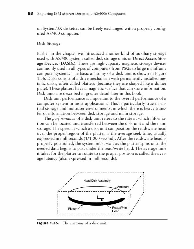
88 Exploring IBM ~ iSeries and AS/400e Computers
on System/3X diskettes can be freely exchanged with a properly config-ured AS/400 computer.
Disk Storage
Earlier in the chapter we introduced another kind of auxiliary storageused with AS/400 systems called disk storage units or Direct Access Stor-age Devices (DASDs). These are high-capacity magnetic storage devicescommonly used in all types of computers from PS/2s to large mainframecomputer systems. The basic anatomy of a disk unit is shown in Figure1.36. Disks consist of a drive mechanism with permanently installed me-tallic disks, often called platters (because they are shaped like a dinnerplate). These platters have a magnetic surface that can store information.Disk units are described in greater detail later in this book.
Disk unit performance is important to the overall performance of acomputer system in most applications. This is particularly true in vir-tual storage and multiuser environments, in which there is heavy trans-fer of information between disk storage and main storage.
The performance of a disk unit refers to the rate at which informa-tion can be located and transferred between the disk unit and the mainstorage. The speed at which a disk unit can position the read/write headover the proper region of the platter is the average seek time, usuallyexpressed in milliseconds (1/1,000 second). After the read/write head isproperly positioned, the system must wait as the platter spins until theneeded data begins to pass under the read/write head. The average timeit takes for the platter to rotate to the proper position is called the aver-age latency (also expressed in milliseconds).
Armature
Read/WriteHead
Platter
Head Disk Assembly
Figure 1.36. The anatomy of a disk unit.
rd-ch01.PMD 10/1/2002, 12:25 PM88

What Is An iSeries or AS/400 System? 89
Finally, once the read/write head is positioned and the data begin topass by on the spinning platter, the information is transferred from the diskunit to the computer system. The speed at which this is done is called thedata-transfer rate and is usually expressed in millions of bytes per second(MBps). The shorter the average seek time and the average latency, and thehigher the transfer rate, the better the performance of the disk storage sub-system and the overall computer system. Figure 1.37 shows the averageseek times, average latency, and data transfer rates for some internal diskunits that are provided as standard equipment on AS/400 systems.
In addition to the disk unit specifications, there are other perfor-mance considerations when configuring the disk storage subsystem ofan AS/400 system. Some disk units have multiple actuators, whereasothers only have one. (The actuator is the accessing mechanism of thedisk unit, which carries the read/write head and flies over the surface ofthe disk detecting or imprinting the magnetic bits.) Often, each actuator
Averate Data Rotation Number ofComputer Standard Disk Seek Transfer Speed Actuators/System Configuration Size Time Rate (rpm) Drives
150 4194 MB 3.5 inch 8.6 20 7200 1
720, 730, 4194 MB 3.5 inch 8.6 40 7200 1740, 170
150, 170, 8580 MB 3.5 inch 8.6 40 7200 1720, 730,740, 250,270, 820,830, 840
150, 170, 17500 MB 3.5 inch 8.6 40 7200 1720, 730,740, 250,270, 820,830, 840
270, 820 8580 MB 3.5 inch 8.6 40 10000 1830, 840
270, 820 17500 MB 3.5 inch 8.6 40 10000 1
Figure 1.37. Performance characteristics of internal fixed disks provided as astandard in AS/400 systems.
rd-ch01.PMD 10/1/2002, 12:25 PM89
90 Exploring IBM ~ iSeries and AS/400e Computers
in a disk unit can perform independently, so the more actuators youhave for a given amount of disk storage, the better the performance. Infact, choosing disk storage configurations that have more actuators fora given amount of storage can result in higher performance than select-ing disk units with faster specifications but fewer actuators. This is par-ticularly true with AS/400 systems because single-level storage tends tospread information over many areas of the disk units. This spreading ofinformation produces more efficient operation because the actuatorscan all share the load, but it does emphasize the need to follow properbackup procedures.
Optical Libraries
Optical libraries consist of arrays of optical disks associated with one ormore optical disk read/write units. In some cases, the optical storage read/write units also have one or more conventional magnetic disk storageunits associated with them to improve the write performance from a sys-tem perspective. The optical disks may be CD-ROM, WORM, or WMRMtechnology, each of which imposes different requirements upon the read/write unit and upon the controller within the system. CD-ROM is anabbreviation for Compact Disk–Read Only Memory, and the technologypresents digital data in a continuous serpentine path across the surface ofthe optical disk. WORM is an abbreviation for Write Once, Read Many.This technology presents data in circumferential paths across the surfaceof the optical disk. Because the data will only be written once, this tech-nology generally has the header embedded on the raw media, and a sec-tor corresponds to the data content that can fit in the shortestcircumferential track. WMRM, sometimes referred to as erasable opticaldisk technology, is an abbreviation for Write Many, Read Many and alsopresents data in circumferential paths across the surface of the opticaldisk. But because the data written at one time must be erased before newdata may be written to replace it, WMRM must follow the sectoring,header, trailer, and error-correction rules of magnetic disk technology,including bad track recovery and directory management.
Tape Storage
The last type of auxiliary storage to be covered is magnetic tape, orsimply “tape.” One primary purpose of tape is to provide a backupstorage medium for information on the computer’s disk storage. The
rd-ch01.PMD 10/1/2002, 12:25 PM90

What Is An iSeries or AS/400 System? 91
low cost and high recording densities inherent in tape make it ideal forarchiving information. Tape is also very useful in distributing programsand transferring information from one computer system to another.Diskettes can be used for these same functions, but the higher storagecapacity of tapes is preferred if you are dealing with a large amount ofinformation. Tape storage consists of a long flexible strip coated withmagnetic material and rolled on a reel or into a cartridge.
Packaging Technology
Most of the circuitry in AS/400 systems was built using IBM’s versionof Very Large Scale Integration (VLSI) technology called Complemen-tary Metal-Oxide Semiconductor (CMOS). This packaging technologybuilds circuits with 0.2 micron sized elements, allowing millions ofhigh-speed transistors in a single chip. Main storage is implementedusing IBM’s 16 Mb and 64 Mb (16 and 64 million bit) memory chiptechnology. Sixteen-megabit chips are used on all except thelargest-capacity memory cards, which use 64 Mb chips to achieve animproved packaging density.
Five basic mechanical designs are used in AS/400 computer systemunits. The sizes range from the deskside tower of the Model 150 to thedual tall-tower racks that house the Models 740 and 840. The systemunit package contains the system processor, main storage, tape, diskunits, a CD-ROM, and some number of I/O controllers.
The main storage for the A10 microprocessor-based processors iscontained on a card that measures about 7 × 3 inches and plugs directlyto the processor card. Main storage Models 170/720 is packaged onstandard DIMM form factor cards. Main storage for the A50 micro-processor-based processors for Models 730/70 is contained on separate9 × 11-inch cards that are plugged into an internal card chasis (called acage), allowing for electrical connections to the bus. The design is modu-lar, and the various elements can easily be added or replaced withoutthe need for IBM service personnel.
All AS/400 systems use the cable-thru wiring scheme. Cable-thru al-lows multiple displays or printers (i.e., workstations) to be attached to-gether in a daisy-chain fashion, as shown in Figure 1.38. With cable-thru,it is not necessary to run a separate cable from the computer to eachworkstation. Instead, a single cable from the computer can be used toattach up to seven workstations over a distance of up to 5,000 feet.
rd-ch01.PMD 10/1/2002, 12:25 PM91
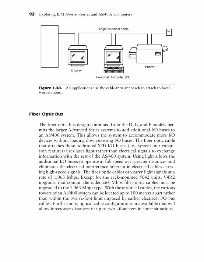
92 Exploring IBM ~ iSeries and AS/400e Computers
Fiber Optic Bus
The fiber optic bus design continued from the D, E, and F models per-mits the larger Advanced Series systems to add additional I/O buses toan AS/400 system. This allows the system to accommodate more I/Odevices without loading down existing I/O buses. The fiber optic cablethat attaches these additional SPD I/O buses (i.e., system unit expan-sion features) uses laser light rather than electrical signals to exchangeinformation with the rest of the AS/400 system. Using light allows theadditional I/O buses to operate at full speed over greater distances andeliminates the electrical interference inherent in electrical cables carry-ing high-speed signals. The fiber optic cables can carry light signals at arate of 1,063 Mbps. Except for the rack-mounted 5042 units, V4R2upgrades that contain the older 266 Mbps fiber optic cables must beupgraded to the 1,063 Mbps type. With these optical cables, the varioustowers of an AS/400 system can be located up to 100 meters apart ratherthan within the twelve-foot limit imposed by earlier electrical I/O buscables. Furthermore, optical cable configurations are available that willallow intertower distances of up to two kilometers in some situations.
...Single twinaxial cable
DisplayPrinter
Personal Computer (PC)
Figure 1.38. All applications use the cable-thru approach to attach to localworkstations.
rd-ch01.PMD 10/1/2002, 12:25 PM92