chapter two layouts and lettering - davis school · pdf filechapter two. layouts and...
TRANSCRIPT

CHAPTER TWO
LAYOUTS AND LETTERING
OBJECTIVES
After studying the material in this chapter, you should be able to:
1. Identify six types of technical drawings based on the projection
system they use .
2. Identify the line patterns used in technical drawings and describe
how they are used.
3. Read and measure with the architects' scale, engineers' scale, and
metric scale.
4. Identify standard drawing media and sheet sizes.
S. Add lettering to a sketch.
6. Fill in a standard title block with the appropriate information.
7. Lay out a drawing sheet.
Refer to the following standards:
• Y14.100-2004 Engineering Drawing Practice • Y14.2M-1992 Line Conventions and Lettering • Y14.1- 2005 Decimal Inch Drawing Sheet Size and Format • Y14.1M-2005 Metric Drawing Sheet Size and Format

23 LAY 0 U T SAN D LET T ERI N G
HCm:1UIU.SSOMR'W:a:! $HOPIfI) THIS PART ISPRODUCED FROMAN ELECTRONIC I """""' I . ...u.~r<S1ON$ARe "" DECtro\AL t«:Hf1. DATAFILE PROVIDED TOTHE VENDOR. DIMENSIONS I 0Cll'1 ..... I OOCIlFlOoC I "''' -.cNflJ 1. RfMOVE AU. m.RRS LStWlP mGt$. 3. M:MOVE ""-LTOOU'<' MA.JlQ. SHOWNAREFORREFERENCE. ANY OTHER DIMENSIONS I I ... ~& lO..fIANCfS StWl al!£D SHOULD BEOBTAINED FROMTHE MODEL.
/IFl EJI"lATJoIGOIl'flGt.
~ 2.500 1.500 I- H·250REF
~ 1
~+ - 1.000
1 \-. $.500
- """'" /1lI;y, .~~~~2S .. I OR2 l«SRATaAR ,....{
HONO OYNOJETRa!AACH.He. XWJ ArofN DllV!.I l\GlAtJE Ml 591 lt lH.fSS O"" BWtSE ~
TOlfiAHCf.S DlOMA1 "'''CT<lNAL U t O.l :1: 1116 FOOT. BRIDGE RAIL EXTENSION TUBE ASSYIt.lCX t 00. """......XXJO:.tO.QXl ,. 224-4WD-2INGROUND co NOTSCAl.ETIe OAAWN:O
c~rED: .. 'nJl7JJ6
AUEIfA1OESlGNS.AAtfAJ-1GEMEN11 NolOP\NI$ NI:llCATEO ORIIIB"lESENTED IVTJ4S OfM.WNO AAE OWNID8f WT V"OA~: .E ' '' m:>o ; I ~AAT OO ""DTHOJE1 tesfAR'Oi we. A.NO waf ~r£D. !'Ia.V(;) ANDD£VB.Ol'tO FORUSE ON N O 1\1~ WITH 21919100 01THE Sf'ECftO POOJECt. tIONESUCHIDEAS. DESI:iHS. ARllANGEMDlT'S cePlANSWJ.llf usm aTOR~0$8) """"''''' .. lrom:>o TO Nlf PERSON. ""'" ORCClRPORAflON~ AHf PI.# ~E WHATSOevE1e WlJ11OU1' T\olf
scae I;l lrltl.E.ASlo.-.1t: I....,WIlfmH~ Of O'f'NOJf1 llEStARCtt He.. OYt<:lJO' I ESEMO l lHC. ~.. tt); JE 5 ,~11r.OIl "'17JJ6 I c< I .
Layout with Title Block of a Small Part at Scale 1:1. Courtesy Dynojet Research, Inc.
OVERVIEW
Two dimensional technical drawings, whether they
are sketched by hand, drawn using instruments,
drawn using a CAD program, or generated from 3D
solid models, follow certain rules so that they can be
correctly interpreted. Unlike artistic drawings, which
communicate self expression and emotional content,
technical drawings communicate how to manufacture
or construct a product, system, or device. In order to
clearly describe this information, technical drawings
adhere closely to formal standards.
These formal standards include systems of projec
tion for developing and understanding drawing views.
They also include an "alphabet of lines," where each
line of the drawing represents certain information.
Lettering is also standardized, to make drawings quick
to create and easy to read and reproduce. Standard
sheet sizes for drawings include a title block that pro
vides important information such as the drawing
name, company information, scale, revision numbers,
and approvals for relea se of the d rawing.
Check the sites below for engineering graphics supplies and equipment
• http://www.reprint-draph ix.com/ • http:/ /www.eclipse.net / -essco /draft/d raft.htm • http: / /www.graphic-design .com /Type /index.htm l

24 C HAP T E R 2 LAY 0 U T SAN D LET T E RI N G
Picture plane or plane of projectiOn)
Projectors ~ h~fe9 d a C
b
(a) Perspective Projection
Pictur e plane or plane of projectiOn)
Parallel projectors ~
(b) Parallel Projection
2.1 The Concept of Projection
2.2 A View of a 3D Object "Projected" onto a Computer Monitor
UNDERSTANDING PROJECTIONS Behind every 20 drawing of an object is a space relationship involving the object and three "imagined" things :
I. The observer 's eye, or station point 2. The plane of projection 3. The projectors (also called visual rays or lines of sight).
Figure 2.1 shows two drawings of a shape projected onto a plane as viewed by an observer, whose eye represents the station point. The lines projecting from the corners (or vertices) of the object are the imagined lines, called projectors.
To understand projection, imagine that the drawing is produced hy points, called piercing points, where the projectors would pierce the projection plane. The drawing may be a twodimensional representation on a sheet of paper, or it may be a two-dimensional representation shown on your computer screen. as shown in Figure 2.2, but the basic principles are the same. One reason 20 projection skills remain relevant, even with the advent of 3D modeling, is that computer monitors still display a 20 view on their flat screens .
Types of Projections There are two main types of projection: perspective and parallel. These are broken down into subtypes as shown in Figure 2.3.
In perspective projections, the projectors come together at the station point to form a cone, as in Figur e 2.1a. Perspective drawings represent objects as we see them or as they would appear in a photograph.
in parallel projections, the projectors are parallel, as shown in Figure 2.1b.
Orthographic projections are one type of parallel projection . In orthographic (meaning right-angle) projections, the parallel projectors are perpendicular to the plane of projection. Because orthographic projections show objects in a way that their features can be represented at true size or scaled at a proportion of true size. they are especially useful in specifying the dimensions needed in technical applications.
If the projectors arc parallel to each other. but are at an angle other than 90° to the plane of projection, the result is called an oblique projection.
Technical drawings of 3D objects usually use one of four standard types of projection, shown in Figure 2.3:
• Multiview • Axonornetric (isometric) • Oblique • Perspective
Multivicw projection shows one or more necessary views. Either of two systems are used to arrange the views in a multiview drawing: Third Angle or First Angle. You will learn about rnultiview projection in Chapter 4.
Axonometric, oblique, and perspective sketches are methods of showing the object pictorially in a single view. They will be discussed in Chapters 14, 15, and 16.
The main types of projection are listed in Table 2.1.

Oblique projection
One-point perspective
RS
Third-angle projection
Trimetric projection
Two-point perspective
1
Three-point perspective
2.3 Classification of Projections
Table 2.1 Classification by Projectors.
Distance from Observer to Clas5 of Projection Plane of Projection Direction of Projectors
Perspective Finite Radiat ing from station point
Parallel Infinite Parallel to each oth er
Obl ique Infinite Parallel to each oth er and oblique to plane of projection
Orthographic Infinite Perpendicular to plane of projection
Axonometric Infinite Perpendicular to plane of proj ection
Multiview Infinite Perpendicular to plane of projection

26 CHAPTER 2 LAYOUTS AND LETTERING
Drawing Vocabulary Drawing line s, lettering, mea surement systems, scale, sheet sizes and title blocks are pre sent ed in this chapter.
Drawing Lines Projected drawing views use spec ific line patterns to repre sent object features. For example, when showing a three dimensional ohject , som e lines represent the edges of surfaces that are hidden from that viewing direction. These hidden line s have a dashed line pattern to help the reader understand the drawing. Another type of line indicates the location of the cent er of a symmetric feature. such as a hole. Familiarity with the type s of lines used in technical drawings help s you read drawings and create drawings that others can easily understand.
Lettering The shapes of letters that arc easy to read and write arc described as part of drawing standards. Often freehand sketching is used early in the design proces s to present ideas and showing note s and information legibly helps present
your ideas to others cle arly. Good lettering often make s or breaks a sketch .
Measurement Systems Two measurements sys tems are used for technical drawings: the met ric sy stem and U.S . enstornury unit s. It is important to be familiar with both measurement systems to create and read drawings that are nsed worldwide.
Scale Obvionsly a large item, a house or bridge for example, cannot be shown full size on a paper sheet. To clearly convey important information about particularly large or small objects, you need to select an appropriate sheet size and show drawings to scale (proportionately smaller or larger than the actual size). Standard lettering sizes for drawings depend on the sheet size .
Title Blocks Company information, the drawing scale , sheet size, and other information is included in a standard title block located in the lower right corner of the drawing to make it easy to locate these important detail s on every drawing layout.
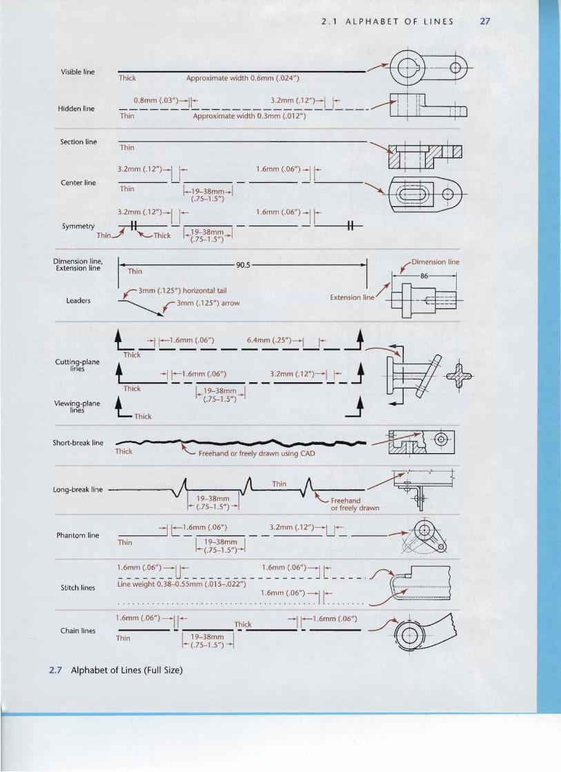
2.1 ALPHABET OF LINES Th e meaning of each line on a technical drawing is indicated by its width (thick or thin) and its particular line style. The person who reads the drawing will dep end on these line styles to know if a line is visible or hidden, if it represents a center axi s, or if it conveys dimension information.
To make your drawings easy to read, make the contrast between thick and thin line s distinct. Thick lines (0.6 rnm) should be twice the width of thin lines (0.3 mm ) as shown in Figure 2.4. The line gage in Figure 2.5 shows various widths.
Figure 2.6 shows freehand line technique. You may find it helpful to lise 1/8 " graph paper at first to get a feel for the length of dashe s used in hidden lines and ccnterlines, Soon you will be able to estimate the lengths by eye .
Figure 2.7 illustrates line styles for technical drawings. All lines (except construction lines) mnst be sharp and dark. For visible, cutting-plane, and short-break lines use thick lines . Thin drawing line s should be just as sharp and black, but only half the thickness of thick lines. Construction lines and lettering guide lines should be thin and light so that they can barely be seen at ann 's length and need not be erased. All lines should be uniform in width and darkness. Ideal lengths of the dashes used to form the line patterns are also shown in Figure 2.7.
Thick (0.60 mm)
Thi n (0.30 mm)
2.4 Thick and Thin Drawing Lines
.007 in . .010 in . .012 in . .014 in. .020 in . .024 in .
.18mm .25mm .30mm .35mm .50mm .60mm
.028 in . .031 in. .039 in. .047 in. .055 in . .079 in.
I I I I .70mm .80mm 1.00mm 1.20mm 1.40mm 2.00mm
2,5 Line Gage
Centerline Dashes Hidden Line Dashes Visible Lines .. ' (Dark and thin with sharp ends) (Dark and th in with sharp ends) (Sharp,dark and thick )
, .. , .. .. , Too indefinite, too light , Too indefinite, too light '" Not a straight path
_____ ___ .-- .... _ . 1' ---------' 4,~.. ~
~
, .. , Too thick for a centerline , Too thic k for a hidd en line 'Too light
2.6 Good and Poor Freehand Line Technique
--
- -
2 . 1 AL P H ABE T 0 F LIN E S 27
Visible line
Hidden line
Section line Thin
3.2mm (.12")-U- _
Center line Thin !-19-38mm- 1
(.75-1 .5")
3.2mm (.12")_1 1Symmetry II - ,.---- -------:
Thin.-l "'-Thick l -g5~~~~ -1
Dimension line, Extension line
Leaders
Cutting-planelines
Viewing-plane lines
~ 1.6mm (.06") _I :....- ~ 1 _
1.6mm (.06") _Ii '-----H-II
• Thin
r 3mm (.125") horizontal tail
~ 3mm (.125") arrow
-I r--1.6mm (.06") 6.4mm (.25")--1 1- !LThiCk -- -- -- -- -- -- -- -~~ ,
t - 11-1.6mm(.06") __3.2mm (·12")- Lt_ J -~+ Thick !-19-38mm_I
(.75-1.5") !l ---JThick
Short-break line --c - ~-Freehandor fr::;'y drawn:::g CAD a-: ~
Thin Long-break line - -J Jl---I' ~~
I 19-38mm I ~ Freehand I- (.75-1.5 ") - or freely drawn
____---'1r-~mm (.06") _ _ 3.2mm (.12")--U~ .-+-~~ . , Phantom line
I 19-38mm I i:% ,/ rThin 1-(.75-1.5")-1 y::X: __ " ,
Stitch lines
Chain lines
1.6mm (.06") ---11 - 11-1.6mm (.06") Thick I
-----~---.-------.;Thin I 19-38mm I
1-(.75-1.5")
2.7 Alphabet of Lines (Full Size)

28 CHAPTER 2 L A Y O UT S AN D LET T ERI NG
2.2 FREEHAND LINES The main difference between an instrument or CAD drawing uniform, as is a CAD or instrument-drawn line. Freehand lines and a freehand sketch is in the appearance of the lines. A good show freedom and variety. Freehand construction lines are freehand line is not expected to be precisely straight or exactly very light, rough lines. All other lines should be dark and clean.
4 X 112.20 THRU 45- -+-+
55- - L.__....u..---''-----'_.L&-......;-'~
:::
10
2.3-
.32-
4 X Rl.3 POCKET T 5
2.8 A Drawing Dimensioned Using Metric Units
4 X ~2 .20 '[}JRU
4 X R2.6.3 POCKET T 1.0
2.9 A Drawing Dimensioned Using U.S. Customary Units
TH RU
r1 «>" 1?l to ".... .... <C
~ ~ '" ~ ...., '" S''<! N -i <ci
2.00 [0.079]
4.6.3 (0.182]4 X 1'12.20 [~0 .0 87]6..38 [0.251]
9.00 [0..354)
11.00 [ 4.3.3J - - L........;_..:.L..---L_......I..---1..L...-......;~
4 XR2.6.3[10.3J POCK ET w 1.0[.04]
2.10 A Dual Dimensioned Drawing Using U.S . Customary Units as the Primary Units
2.3 MEASUREMENT SYSTEMS When you create a technical drawing, the item you show will be manufactured or constructed using a particular system of measurement, which you indicate on the drawing. The metric system is the world standard used for measuring lengths.
U.S. Customary Units u.s. customary units based on inch-foot and yard measurements (where a yard equals exactly 0.9144 meters, there are 3 feet to the yard. and 12 inches to the foot) continue to be used in the United States. Drawings may use either measurement system and still follow ANSI!ASME drawing standards as long as the system of measurement is stated clearly on the drawing. Figure 2.8 and Figure 2.9 show the same part dimensioned with the two different measurement systems.
The Metric System Today's metric system is the International System of Units. commonly referred to as SI (from the French name, Ie Systerne Internat ional d' Unites), It was established in 1960 by international agreement and is now the international standard of measurement, with all countries in the world adopting it, although some continue using traditional U.S. units to a greater or lesser degree.
The meter was established by the French in 179 1 with a length of one ten-millionth of the distance from the Earth's equator to the pole. A meter equals 39.37 inches or approximately 1.1 yards.
The metric system for linear measurement is a decimal system similar to the U.S. system of counting money. For example,
Imm = I millimeter ( 1/1000 of a meter) [ em = I centimeter (1/100 of a meter)
= IOmm Idm = I decimeter ( 1/lO af a meter)
10cm = l aO mrn
1m = I meter = 100 ern = 1000 mrn
lkm = 1 kilometer = 1000 m = 100,000 ern = 1,000 ,000 mm
The primary unit of measurement for engineering drawings and design in the mechanical industries is the millimeter (rn rn). Secondary units of measure are the meter (m) and the kilometer (km). The centimeter (em) and the decimeter (dm) are rarely used on drawings.

2 . 4 D R AW I N G s c x L E 29
Som e indus tries ha ve used a du al dimensioning system of millimeters and inches on drawings. However, this pract ice can be con fusing becau se the sizes displ ayed in the two sys tems may contain rounding enol's. If two systems are shown, the primary unit s are used for a ll manufacturing measurement s and the seconda ry system unit s (sho wn in parenth eses) are for ge nera l information purp oses only. Figure 2.10 shows a drawin g using dual dimen sioning. Most large manufa cturers use all met ric dimension s on the draw ing for ease and consistency .
Many of the dimensions in the illustrati ons and the problem s in this text are give n in metric unit s. Dim en sions that are give n in U.S. customary units (inches and fee t, either decimal or fract ional ) can be conv erted eas ily to metri c values. In standard practice, the rat io J in. = 25.4 ITIm is used. Decimal equivalent s tables can be found ins ide the back cover, and conv ersion tables are give n in Appendix 3 1. Many hand y unit conversion sites are also avail able on the Web, at sites such as www.onl ineconversion .com.
2.4 DRAWING SCALE
Unlike dra wing using a computer (where an object is drawn at Scale is stated as a ratio of the number of drawing unit s to its actual size so that the inform at ion stored in the computer file the number of actual units. For exa mple, a machine part may be is acc urate) a pri nted or paper drawing may represent the ob shown on a shee t at half its actual size . a scale of I :2; a buildject at its ac tual size (full size) , or may be larger or smaller than ing may be drawn 1148 of its size , a scale of 1:48 (or in U.S. the object, dep ending on the size of shee t used . Drawing scale customary unit s, 114" =I'); a map may be drawn 1/1200 actual is the reduction or enlargement of the drawn object relative to size, a scale of I" = I00 ' o r I :1200 ; or a print ed circuit board the real object (Figure 2. 11). may be drawn four time s its size, a scale of 4:1.
Planeof projectiOn) H,1fscale ' 2 l Twi" scale 2" ~
fL., , ~ D~
Full scale 1:1~ 2.11 Reduced and Enlarged Scale. Many drawings must be shown at reduced scale for the object to fit on the pap er.
2.5 SPECIFYING THE SCALE ON A DRAWING
There are severa l accept abl e meth ods to note scale on the drawin g, but all of them sho w the relation ship of the size of the objec t as drawn to the size of the ac tua l objec t. For a part that is shown on the pap er at hal f its actual size, list the sca le one of these three ways :
SCALE: 1:2 SC ALE: 1/2 SCALE: .5
For machin e drawings, the sca le indic ates the ratio of the size of the drawn object to its ac tua l size, regardle ss or the unit of measurement used. Expansion or enlarge ment sca les arc given as 2: I, 4:1; 5:1, 10:1, and so on. Figure 2. 11 illustrates how the actual object relates to a drawing at half size and how that might be noted in the title block of the drawing. Figure 2.12 shows the scale for a I to 24 redu ction noted in a title block.
Architectural drawings in the U.S. typically list the scale based on the number of fractions of an inch on the drawing that represent one foot 0 11 the aetna] object. For example, SCALE : 118" =I'.
The various sca le ca libra tions available on the metri c scale and the engineers ' sca le provide alm ost unlimited sca le ratios.
Preferred metri c scale ra tios arc I: I; I:2; I :5, I :10, I :20, 1:50, I: 100, and 1:200.
Map sca les are indicated in terms of proportions suc h as Scal e 1:62500 , fractions such as Seale 116250 0, or graphically, such as 400 0 400 800 Ft
111M. , , •
224j224-4W D IN G ROUND DYNO Sta nd ard Whe el Base 88 X 130
8 1224103
i!O.t.A$fDAft: 2123noo1
2.12 List Predominant Drawing Scale in the Title Block. Courtesy of Oynojet Research, Inc.

30 CHAPTER 2 LAYOUTS AND LETTERING
2.6 SCALES Scales are measuring tools used to quickly enlarge or reduce drawing measurements. Figure 2.13 shows a number of scales, including (a) metric, (b) engineers' , (c) decimal (d) mechanical engineers', and (e) architects' scales. On a full-divided scale, the basic units are subdivided throughout the length of the scale . On open-divided scales. such as the architects' scale, only the end unit is subdivided.
Scales are usually made of plastic or boxwood. The better wood scales have white plastic edges. Scales can be
(a) Metric scale
(b) Engineer's scale
(c) Decimal scale
(d) Mechanical Engineer's scale
(c) Architect's scale
(I) Scale guard
2.13 Types of Scales
either triangular or flat. The triangular scales combine several scales on one stick by using each of the triangle' s three side s. A scale guard shown in Figure 2.l3f can save time and prevent errors by marking the s ide of the scale currently in use .
Several scale s that are based 011 the inch-foot system of measurement continue in domestic use today, along with the metric system of measurement, which is accepted worldwide for scien ce, technology, and international trade .

2.7 METRIC SCALES Metr ic sca les are ava ilab le in flat and triangular styles with a variety of scale graduations. T he triangular sca le illu strated (Fig ure 2. 14) has one full-size scale and live reduced -size sca les, all fully divided . Using these sca les, a drawi ng can be made full size, enlarged size d, or reduced sized.
Full Size The I : I scale (Fig ure 2.14a top ) is full size , and each division is actuall y I mm in width with the num bering of the calib rations at 10 mrn inter vals. The same sca le is also con venient for ratios of I :10, I :100, I : WOO, ancl so on.
Half Size The 1:2 sca le (Figure 2. 14a bottom) is onehalf size, and eac h divi sion equals 2 m in wi th the calibra tion
2 . 7 M ETRIC SC ALES 31
numbering at 20- unit intervals. Thi s scale is also co nve nient for rati os of 1:20, 1:200. I :2000, and so on.
The rema ining four scales on this tri angular metr ic sca le include the typ ical sca le rati os of I :5, I :25. and I:75 (Figures 2. 14b and c). Th ese ratios may also be enlarge d or redu ced by multipl ying or dividing by a factor of 10. Met ric sca les are also avail abl e with othe r sca le ratios for specific draw ing purposes.
Metric scales are also used in map drawin g and in drawing force diagrams or other graphical construc tions that involve such sca les as I mm = I kg and I mITI = 500 kg .
"\\ ' \ , \" \ \ \" " \" \ I \ ' \,1\1" I \
nil 'l1\lI ~ >Il\lmm
'I
1'''''1m ~ w; 11'1'> Ill.'> \lIl'> ~ ISV
\ 1\ "\,,, ,\ \ I \,\" I1\'" 1\ II ",,'1\""\,, ,,\\1\ 1\ I \1'\""\,, 1'\"" 'I ,\
1--- - - -48.5 mm - - - - I1:1 Ratio metric-scale (full size)
2mml'I-35mm
-49mm
(a)
1:2 Ratio metric-scale (half-size)1------- 290 mm ------11:5 Ratio
metric-scale 1-- -175 mm--(one-fifth size)
(b)
L 20 mm--1r 1:25 Ratio 50 mm- metric-scale
' / - 1-5 mm
,~ \ ~ ~ ~ ~ \ ~ ~ ~ ~ \ ~ ~ ~ ~ \ V ~ ~ ~ \ ~ ~ ~ V \ ~ V ~ ~ \ ~ ~ I ~ ~ \ ~ ~ ~ \ V ~ ~ ~ \ 0 0 ~ \ \ ~ ~ ~ ~ \ II \~m 'lllIl ~,~ \0\00 \SOOmm
_ 1000 mm (1 meter)_ 1:33'/) Ratio metric-scale
(c)
1:75 Ratio metric-scale
2.14 Metric Scales

32 CHAPTER 2 LAYOUTS AND LETTERING
MAKING MEASUREMENTS TO LAY OUT A ONE-FIFTH SIZE METRIC DRAWING
3500~
I 2500
, -2500-
- 500 -
f I I1100
~
Determine the full size measurements of the object you will draw. This example will layout a 3500 x
2500 111m flat plate with a rectangular slot in it. A picture of the part to be drawn with dimensions representing its actual size is shown above .
Find your 1:5 ratio metric scale. like this one.
Starting from the 0 end of the 1:50 scale, use a sharp pencil to make a thin , light. short line to mark off the
length of the 3500 nun line. To make accurate mea surements. be sure to place the scale edge parallel to the line you are measuring on the drawing. and make your dashes at right angles to the scale. at the correct graduution mark, as shown.
full metric scale 70 rnrn, on the: ,::::---
Check length of your scaled line by calculating how many millimeters the length should he. then measur
ing the line you have drawn with a full scale metric scale. In this case the 3500 rnm length should be 70 rum when shown at I :50 scale.
e--: For accuracy, mark several distances wi thout repositioning scale
Continue to layout the remaining lengths. Even slight errors in measurements when using a scale may accu
mulate to produce a significant error, so work carefully.
To avoid cumulative errors. instead of setting off distances individually by moving the scale to a new position each time . po sition the scale once and mark all of the distances by adding each success ive mea surement to the preceding one .
This is useful in dimensioning drawings, too . Keep in mind that providing dimensions from one end to each successive location (say. in the case of building a wall) makes it easier for the worker to lay it out quickly and accurately.

2 . 8 ENG I NE ERS' Se A L ES 33
2.8 ENGINEERS'SCALES An Engineers' scale is a decimal sca le graduated in unit s of I inch divided into 10,20,30,40,50, and 60 parts. These scales are also frequently called the civil engineers ' scales becau se they were originally used in civil engineering to draw large scale structures or maps. Som etimes the engineers' sca le is referred to as a chain scale . because it derived from a chain of 100 links that surve yors used for land measurements.
Becau se the eng ineers' scale divides inches into decimal units, it is co nve nient in machin e drawing to se t off inch
dim ensions expressed in decimals. For example, to set off 1.650 " full size, use the 10 scale and simply set off one main div ision plus 6-1/2 subdivisions (Fig ure 2.15 ). To set off the same dimension half size , use the 20 sca le, since the 20 scale is exactly hal f the size of the 10 scale. Similarly. to set off the dimension quarter size, use the 40 scale.
An engineers' scale is al so used in drawing stress diagrams or other graphical co nstructions to such scales as I" = 20 lb. and I" = 4000 lb.
2.15 Engineers' Scale
2.9 DECIMAL INCH SCALES The wide spread use of decimal inch dim ension s brought abou t quarter-size decimal sca les , the inches are compressed to half a scale spec ifica lly for that use. On its full- size scale, each incb size or quarter size and then are divided into 10 part s, so that is divided into fiftieths of an inch , or .02". On half- and each subdivisio n stands for . 1" (Figure 2. 16).
2.16 Decimal Inch Scale
2.10 MECHANICAL ENGINEERS' SCALES The objects represent ed in machin e draw ing vary in size from These scales are useful in dividing dim ensions. For examsmall parts that measure only fractions of an inch to part s of ple. to draw a 3.6" diameter circ le full size, we need half of 3.6" large dimension s. For this reaso n, mechanical enginee rs' scales to use as radiu s. Instead of using math to find half of 3.6" . it is are divid ed into units representing inche s to full size, half size, easier to se t off 3.6" on the half- size sca le. quarter size, or eighth size (Figure 2.17). To dra w an object to .---- TI P ---------------,a scale of one-half size , for example. use the mechanical engi
Triangular combination scales are available that include neers' scale mark ed half size , which is graduated so that eve ry tull- and half-size mechanical engineers' scales, several 1/2" represents I 'I. In othe r word s, the half- size sca le is simply architects ' scales, and an engineers' scale all on one stick. a full-size scale compressed to half size.
2.17 Mechanical Engineers' Scale

34 CHAPTER 2 LAYOUTS AND LETTERING
Full size scale (16 divisions per inch)
Note that the increments for the 3/16 scale begin at the 0 closest to the scale indicator
2.18 Architects' Scale
2.11 ARCHITECTS' SCALES The architects' scale is intended primarily for drawings of buildings. piping systems, and other large structures that must be drawn to a reduced scale to fit on a sheet of paper. The full-size scale is also useful in drawing relatively small objects, and for that reason this scale has rather general usage.
Architects' scales have one full-size scale and ten reducedsized scales. (To fit them all on a three-sided scale, there arc two scales on the same edge of the scale , but each starts from the opposite end. Simply find the scale you want, and read the units from the zero closest to that end .
Architects ' scales can be used to draw various sizes from fuJI size to 1/128 size . In all of the reduced scales, the major divisions represent feet and their subdivisions represent inches and fractions of inches .
Note that on an architects' scale. the scale mark ed 3/4 means 3/4 inch =I foot , not 3/4 inch =1 inch (that is, it means one -sixteenth size, not three-fourths size). Similarly. on an architects' scale. 1/2 mean s 1/2 inch = I foot , not 1/2 inch = 1 inch. In other words. on an architects ' scale, 1/2 means twenty-fourth-size, not half size.
Start at this 0 for measurements using the 3/32 scale _
• Full Size: Each division in the full -size scale is 1/16" (Figure 2.18). Each inch is divided into halves, then quarters, eighths, and finally sixteenths. You'll notice that the dividing lines are shorter with each subdivision. Measurements smaller than 1/16" must be made by estimating. For example, 1/32" is half of one 1/16", so you would visually estimate halfway between 1/16" division lines. To measure 1/64", you would estimate one fourth of 1/16", and so on .
• Half Size : Use the full-size scale, and divide every dimension by two. (Remember, do not use the 1/2" scale, which is intended for drawing to a scale of 1/2" = I', not half-size .) To create a half scale drawing using an architects' scale, divide your measurements in half and then layout the drawing.
• Double Size: Use the full-size scale. and multiply every dimension by 2.
.---- TIP ---------------, AutoCAD software users sometimes become confused using architectural units. When selecting architectural units in which to enter lengths, keep in mind that a value of 1 is one inch, not one foot.

2.1 1 ARC H I TEeT S' SCAL E S 35
MEASURING WITH AN ARCHITECTS' SCALE
increments (in this case, I at full scale
\\
\\, II
\'1.
\ ~
\\ 'I.
\~
\
Fractional division lines represent' " at full scale*
DECK
I SCALE 3/8" = "
To make measurements with an architects' scale, first determine
which scale to lise hy reading the scale noted in the title block or noted below the view. In the example above, 3/8 inch = I foot.
Position the scale so that the 0 value is aligned with the left
end of the line being measured and note the division mark nearest to the line's right end (in this case, 2).
Slide the scale to the right so that the closest whole division you
noted in Step 2 lines up with the right end of the line you are measuring. A fractional portion of the line you are measuring now extends on the left, past the scale's 0 mark.
Counting toward the left, note how many fractional division marks are between zero and the left end of the line. (In this example, there are two.)
Add the fractional value to the whole . value that you noted in Step 2. In this example. you noted 2 whole division lines, plus two fractional division lines, so the length of the line is 2'-2" at actual size.
Division lines represent 3/8"
DECK
DECK
Add the inches, counti ng
Division line is now aligned with the other end of
\ II
\'1.
\ \\
~
\'),
\ /
the line being measured
back from the 0 value
'On architects ' scales, there lire 12 fractional divisions, because there are 12 inches per/oat.

36 CHAPTER 2 LAYOUTS AND LETTERING
ABCDEFGH abcdefgh Sans-serif lettering has no serifs, or spurs, at the ends of the strokes
ABCDEFGH abcdefgh Roman letters are accented by thick and thin line weights
ABCDEFGH abcdefgh Italic letters are slanted, whether serif or sans serif
2.19 Distinctions Between Roman, Italic, Serif, and Sans Serif Lettering
AUTOCAD TXT FON T ROMAN SIMPLEX ROMAN DUPLEX
TITLES l{~VP' l{eycp£ POJfl'S
2.20 An Example of Lettering and Titles Using CAD
2.12 LETTERING Lettered text is often necessary to completely describe an object or to provide detailed specifications. Lettering should be legible, be easy to create, and use styles acceptable for traditional drawing and CAD drawing.
Engineering drawings use single-stroke sans-serif letters because they are highly legible and quick to draw . (San s-serif means without serifs, or spurs.) A font is the name for a particular shape of letters . The particular font for engineering drawings is called Gothic. Figure 2.19 shows the distinctions between Roman, italic, serif and sans serif fonts .
Lettering is a standard feature available in computer graphics programs. With CAD software, you can add titles, notes , and dimensioning information to a drawing. Several fonts and a variety of size s may be selected . When modifications arc required, it is easy to make lettering changes on the drawing by editing existing text.
Freehand lettering ability has little relationship to writing ability. You can learn to letter neatly even if you have terrible handwriting. There are three necessary aspects of learning to letter:
• knowing the proportions and forms of the letters (to make good letters, you need to have a clear mental image of their correct shape)
• spacing of letters and words for legibility • practice
2.13 LETTERING STANDARDS Most hand-drawn notes use lettering about 3 mm (1/8") in height. Light horizontal guidelines are useful to produce con sist ent letter heights. CAD notes are set using the keyboard and sized to be in the range of3 mm ( 1/8") tall according to the plotted size of the drawing. Lettering heights vary with the size of the sheet and the intended use of the drawing.
CAD drawings typically use a Gothic lettering style, but often use a Roman style for titles. When adding lettering to a CAD drawing, a good rule of thumb is not to use more than two fonts within the same drawing. See Figure 2.20 for a sample of the fonts available using CAD . You may want to use one font for the titles and a different font for notes and other text. It may be tempting to use many different fonts in a drawing because of the wide variety available, hut this tends to look distracting on the drawing. Drawings that use too many lettering styles and size s have been jokingly referred to as having a "ransom note" lettering style.
2.14 VERTICAL LETTERS AND NUMERALS There are standard widths for the various letters. The propor probably a little wider than your usual writing. It is easier to tion s of vertical capital letters and numbers are shown in remember the six-unit letters if you think of them as spelling a Figure 2.21. In the figure, each letter is shown on a 6-unit-high name: TOM Q. VAXY. The letter I is a pencil width , and the grid that shows its width in relation to its height. The numbered letter W is eight grid-units wide (1-1/3 times its height). arrows indicate the traditional order and direction in which the With the exception of the numeral 1, whieh uses only a lettering strokes are made. pencil width , all numerals are five units wide.
Aside from the letters I and W, letters are either five or six grid divisions wide, or about as wide as they are tall. Thi s is
2.15 LOWERCASE LETTERS Lowercase letters arc rarely used in engineering sketches except for lettering large volumes of notes . Vertical lowercase letters are used on map drawings, but very seldom on machine drawings. Lowercase letters are shown in Figure 2.22. The lower part of the letter (or descender) is usually two-thirds the height of the capital letter.
When large and small capitals are combined, the small capitals should be three-fifths to two-thirds the height of the large capitals. The inclined letters and numbers shown in Figures 2.23 and 2.24 will be discussed in the next section.

2 . 1 5 LOW ERe A 5 E LET T E R 5 37
Straight-line letters 1--
11I~11 UJH f ~ 11~ 11~; l' lgWZt: 1 ~ t t}12 ..l ffi t~~ ~f\' - ~j ~ fJ l+'_j l-Bffi3W j Iftt-I , ~\ /~ 1{3 \ \1 ~ 2- 2"- Letter "i" has short bars
1\~ V110i 11 r3 ~~1 1 11~~I r{%t1 tt'7" 1
A!~4f, 2 2 . ~~ [ 1I .t1j ~ ~t1 1 11 1ft±{] ' rt2~ ~~1J t 1 1 l:+ r J ~ 3"- "W" is only letter over 6 units wide. Letters in "TOM Q. VAXY" are 6 units wide -all others are 5, except " I" and "W"
Curved-line letters
rn. "~ :,f~~ ~l ~~-' ," . ; t.flH 1~Ufi. l '' . . ) lt-JIJ 1 l~'UI :"+;W) ~l ~ '~I ,~; ~i The letters 0, Q, C, G and 0 are based on a true circle. The lower portion of of the) and U is elliptical
Curved-line letters and numerals
The 8 is composed of two ellipses.The 3, S, and 2 are based on the 8
Curved-line letters and numerals
Number "1" is a straight line. The 0, 6, and 9 are elliptical
2.21 Vertical Capital Letters and Numerals
2.22 Vertical Lowercase Letters

38 CHAPTER 2 L A Y O UT S AND LE TT E RI N G
Straight- line lette rs 1
I/li;~- ;/!fj~~~~:;IE:H AV~W 2l 2 _
'I;,.,. Letter " i" has short bars
+j;"'~+f--745~
Curved- line lette rs
/ """"---' '''''
{~ 2 2;t ". " / {j_ ~ /_ --..c. T I'(@ ~j //,I/JJIjj+--0 \ . r- "7 1 I
J J L' " 1 I ~I ~
The letters 0 , Q, C, G and D are based on a true ellipse, The lower portion of of the I and U is elliptical
Curved-line letters and numeral s
Cur ved-line letters and numerals
Number " 1" is a straight line, The 0, 6, and 9 are elliptical
2.23 Inclined Capital Letters and Numerals
2.24 Inclined Lowercase Letters

39 2 . 1 6 INC LIN ED LET T E R SAN D N U M B E R S
2.16 INCLINED LETTERS AND NUMBERS Inclined (italic) capital letters and numerals, shown in within a drawing so that the lettering is consistent. Inclined Figure 2.23, are similar to vertical characters, except for the lowercase letters, shown in Figure 2.24 , are similar to vertical slope. The slop e of the letters is about 68° from the hori zontal. lowercase letters .
Whi le you may practice drawing slanted hand lettering at Keep in mind that only one style of lettering. e ither vertiapproxima tely this angle, it is important in CAD dra wings to cal or inclined, should be used throughout a drawing. a lways set the amount of incline for the letters at the same value
2.17 FRACTIONS Fractions are shown twice the height of the corresponding whole numbers. Make the numerator and the denominator each about three-fourths as high as the whol e number to allow enough space between them and the fracti on bar. For dimensionin g, the most co mmonly used height for whole numb ers is 3 mrn (1/8"), and for fractions 6 mm (1/4 "), as shown in Figure 2.25.
• Never let num eral s touch the fraction bar. • Center the denominator under the num erator. • Avoid using an incl ined fraction bar , except when lettering
in a narrow space, as in a part s list. • Make the fraction bar slightly longer than the wide st part
of the frac tion.
1 2515 1 Y28 4 4" 2 32 (a) (b) (c)
2.25 Common Errors in Lettering Fractions
2.18 USING GUIDELINES Use extremely light hori zontal guidelines to keep lette r height uniform. as shown in Figure 2.26. Capit al letters are co mmonly mad e 3 111m (1/8 ") high , with the space betw een row s of letter ing being from three-fifths to full height o f the letters. Do not use vertic al guidelines to space the di stance from one letter to the next within a word or sentence . Thi s should he done by eye while lettering. If nec essary , use a vertica l guideline at the beginn ing of a co lumn of hand lettered text to help you line up the left edges of the following rows . Beginners can also use randoml y spaced vertical guidelines to practice maint ainin g the correct slan t.
r--- TI P -------------, For even freehand letters • Use 1/8 " gr idded paper for drawing to make lettering
easy. • Use a scale and set off a series of spaces, making both the
letters and the spaces between lines of letters 1/8" high. • Use a gu ideline template like the Berol Rapidesign 925
shown in Figure 2.27 . • For wh ole numbers and fractions, draw five equally
spaced guidelines.
( vertical guide lines dra.wn.at random
IG1E-[[IEB1lSJILlb-'E~S]~±.I _+ I + -+-~-'+-I-1-t-I I 1 1 1 1 I
1 F r:t1 q:~ p;~ -~ 0~['H-YB-~.--yB- _ ~ -_\:-\J:S_EL~~q]I~JI_tUSlES---+-~
Space between lines usually from ! to total height of letters
2.26 Using Guidelines
REVERSEWITl-I INKING PEN
~ (---- - - -- - - - - - 1---..) '4
12 (----- - - - - - - - - --------.,) ~
1
]' C:::=====================:::JJ12
~ c:::==========================:::)d-BeroLRopiDesign. R-925 LEITERING AID
2.27 The Berol Rapidesign 925 Template Is Used to Quickly Create Guidelines for Lettering

40 CHAPTER 2 LAYOUTS AND LETTERING
2.19 SPACING OF LETTERS AND WORDS LATHING Spacing Between Letters Uniform spacing between letters is done by eye. Contrary to what might seem logical, putting equal distances from letter to letter causes them to appear unequally spaced. The background areas between letters, not the dis
L may be shortened when followed by A. In typesetting, pairs of letters that need to be spaced more closely to appear correctly are called kerncd pairs.
Spacing Between Words
u u u UJ u
literate L.U U u u U U
Using equal spacing from one letter to another does not actually appear equal, as in this example
tances between them, should be approxi Space letters closely within words to make mately equal to get results that appear each word a compact unit, but space words balanced. Figure 2.28 illustrates how using LATHINGwell enough apart to be clearly separate from U I U L....L....J L...J
equal spacing from one letter to the next does adjacent words. For both uppercase and lownot actually appear equal. Space your letter ercase lettering, make spaces between words liierateing so that background areas appear equal, L.LJ U LJ U W Uapproximately equal La a capital O. like the example shown in the bottom balf of
Spaceyour lettering so that the figure . background areas appear equal, Spacing Between Rows Some combinations, such as LT and VA, like the example shown above
may have to be slightly closer than other let Be sure to leave space between rows of letter2.28 Visually Balancing
ters to look correctly spaced. In some cases, ing, usually equal to the letter height. Rows Letter Spacing
the width of a letter may be decreased spaced too closely are hard to read. Rows slightly. For example. the lower stroke of the spaced too far apart do not appear Lahe related.
,--- TIP --------------------------------., Creating letters that appear stable A good example
of uniform lett ering RELAT IVELY Certain letters and numerals appear top-heavy when they are drawn with equal upper and lower portions These examples show what not to do like the example below.
To correct this, reduce the size of the upper portion to Nonuniform style
give a balanced appearance, as in this example.
Ifyou put the central horizontal strokes of the letters B, E, F, and H at midheight, they will appear to be below
REL AT IVE.LYcenter. Nonuniform letter height RELAT IVELYTo overcome this optical illusion, draw the strokes for
B, E, F, and H slightly above the center as you letter, keeping letters uniform, as in the second example below.
Nonuniform R'LLAT !V E LY angle RELATIVELY
Nonuniform RE LATIVELY stroke thickness RELATIVELY
The same practice applies to numerals. In the illustrations below, the example at left looks top-heavy. Nonuniform RELATIVELY Note how the example at right looks more balanced . letter spacing
NOW IS THE TIME FOR EV E RY Nonun iform GOOD PERSON TO COME TO THE
word spacing AID 0;: ....rs OR HER COUNTRY

2 .20 LET T ERI N G F OR TI T L ES 41
2.20 LETTERING FOR TITLES In most cases , the title and related inform ation are lett ered in title boxes or title strips as shown in Figure 2.29 . The main drawing title is usually centered in a rectangular space, which is easy to do, using CAD.
When lettering by hand , arrange the title symme trically about an imagin ary centerline, as shown in Figure 2.30 . In any kind of title , give the most important words prom inence by making the lettering larger. heavier, o r both . Other data, such as scale and date, can be smaller.
Figure 2.31 shows examples of freehand lettering at actual size .
TOOL GRINDING MACHINE. TOOL REST SLIDE
SCA L E : F UL L SIZ E
AMERICAN MACHINE. COMPANY NEW YORK CITY
DRAWN ev _ CHE CKED BY _
2.29 Balanced Machine-Drawing Title
Scrap of paper underneath
2.30 Centering Title in Title Box
2.31 Pencil Lettering (Full Size)
,--- TI P ---------------------------------, Lettering with a Pencil • Since practically all pencil lettering will be reproduced, the
letters should be dense black, not gray or blur red. Use a sharp, soft pencil, such as an F, H, or HB to make lettering dark and sharp.
• If you like using wooden pencils, sharpen them to a needle point, then dull the po int very slightly.
• Don't worry about making the exact letter strokes unless you find it difficult to make the letters look right, but do use them as a reference if you are having trouble drawing uniform, symmetrical lette rs.
• Use extremely ligh t, 1/8 " (3 mm ) horizontal guidelines to regulate the height of letters.A few light, vertical or inclined lines randomly placed help you Visually keep the letters uniformly vert ical or inclined .
• Draw vertical strokes downward with a finger movement.
• Draw horizontal strokes from left to right with a wrist movement and without turning the paper. lE
• Draw curved strokes and inclined strokeswith a downward motion.
Leit-handers: Traditional lettering st rokes were designed for right
Vertical handed people . Exper iment with each letter to find out which strokes are best and develop a system of stro kes that works best for you .
Inclined

42 CHAPTER 2 LAYOUTS AND LETTERING
2.21 DRAWING PENCILS High-quality drawing pencils help produce good quality technical sketches and drawings . Use light lines for construction lines, lettering guidelines, and precise layout work. Use dark, dense black lines for the final lines, lettering, and arrowheads. Drawings are often reproduced and the lines need to be dark for the copies to turn out well.
Drawing pencils are made of graphite with a polymer hinder or clay binder. They are divided into 18 grades from 9H (the hardest) to 7B (the softest) as shown in Figure 2.32. Specially formulated leads of carbon black particles in a polymer hinder are also available in several grades for use on polyester film (mylar) .
Hard leads are used where accuracy is required, such as on graphical computations and charts and diagrams. For other uses, their lines are apt to be too light.
~/Y~.' ~
9H 8H 7H 6H 5H 4H
Hard The hard leads in this group (left) are used whereextreme accuracy is required, as on graphical computations and chartsand diagrams. Thesofter leads in this group (right) are sometimes usedfor line work on engineering drawings, but theiruse is limited because the lines are apt to be too light.
2.32 Lead Grade Chart
~ Sharp conical point for general line work
Drafting penci l leads avai lable in all grades
~ Thin leads require no sharpening
2.33 Drawing Pencils
3H 2H H F HB B 2B 3B 4B 5B 6B 7B
~
Medium These gradesare for general purpose work in technical drawinq. The softer grades (right) are used for technical sketching, lettering, arrowheads, and other freehand work on mechanical drawinqs, The harder leads (left) are usedfor line work on machine drawinqs and architectural drawinqs, The Hand 2H leads arewidely usedon pencil tracinqs for reproduction.
Soft These leads are too soft to be useful in mechanical drafting. They tend to produce smudged, rough lines that are hard to erase, and the leadmust be sharpened continually. These gradesare used for artwork ofvarious kinds, and for full-size details in architectural drawing.
(a) Grade Mark Drawing Pencil Donot sharpen
this end!
(b) Mechanical Pencil
(c) Thin-Lead Mechanical Pencil
Medium leads are used for general purpose technical drawing, such as sketching. lettering, arrowheads, and other freehand work on mechanical drawings.
Soft leads are not useful in technical drawing. They make smudged, rough lines that are hard to erase, and the lead dulls quickly. These grades are generally used for artistic drawing.
Whieh grade of pencil works best for you depends on your hand pressure, the humidity, and the type of paper you are using. among other things. For light lines, use a hard lead in the range of 4H to 6H. For dark lines. use a softer lead in the range of 2H to B.
Mechanical pencils are available with 0.3-, 0.5-, 0.7-, or 0.9-mm-diameter drafting leads in several grades (Figure 2.33). Their thin leads produce uniform-width lines without sharpening. The .5-mm lead is a good general size, or you can use a .7-mm lead for thick lines and .3 mrn for thin lines.
r-- TI P -------, You might be surprised how much your drawings benefit from finding a style of pencil that suits your use. Soft pencils, such as HB or F, are mainly used in freehand sketching. Choose a pencil that:
• Is soft enough to produce clear black lines, but hard enough not to smudge too easily
• Is not so soft that the point breaks easily.
• Feels comfortable in your hand . • Grips the lead without slipping.
Be aware that some lead holders require special sharpeners.
You can sometimes tell the difference in hardness of a mechanical pencil lead just by looking at it. Smaller diameter leads are used for the harder grades and larger diameter leads are used to give more strength to the softer grades.
Plain wooden pencils work great. They are inexpensive, and it is easy to produce thick or thin lines by varying the amount that you sharpen them. An old trick to keep the lead sharp longer is to turn the pencil frequently as you work to wear it down evenly.
Gum erasers and nylon erasers work well to pick up smudges without leaving much eraser dust.
Nylon eraser strips that come in refillable holders likemechanical pencils can be convenient for areas that require some precision. A trick for erasing fine details is to sharpen the end of the eraser strip in a small hand-held pencil sharpener.

43
2.22 TEMPLATES
Templates are available for a great varie ty of specia lized needs (Figure 2.34). Templates may be found for drawing almost any ordinary draft ing symbols or repetitiv e feature s,
2.23 THE COMPUTER AS A DRAFTING TOOL Most people who creat e technic al drawings usc CAD. Advantages includ e accuracy, speed, and the abilit y to present spatial and visual information in a variety of way s.
However, these advantages don 't eliminate the need for drawin gs to be easily and accurately interpreted. CAD drawings use the same general concepts and follow the same draftin g standards as drawings created by hand.
Most CA D drawings are plotted on standard shee t sizes and to similar scales as hand drawings. Both CAD and hand drawings should contrast thick lines for objects with thin lines for hidden , center, and dimensions to make the print ed drawing easy to read . CAD drawings
should use co rrec t line patterns. Likewise, lettering on CAD draw ings should follow these same general guidelines as for hand drawings.
One benefit of CAD is the ability to draw perfe ctly straight uniform lines and otber geo me tric elements. Another is the ability to quickl y represent the various styles of lines (Figure 2.35). Making changes to a CAD draw ing takes about a tenth the time that it takes
7 ! r . ,.
/" 2.34 Drawing Templates. Courtesy of Chartpak.
2 . 2 2 T E M P L ATE S
to edit a drawing by hand . Using CAD, you ca n quickl y plot drawings to different scales.
Keepin g CAD drawing files organized, backing up data regularly, and followin g conventions for naming files so that you can find them aga in are important considerations. Even the most skilled CAD user s need to also be skilled in freehand sketching, in order to quickly get ideas down on paper.
Chin ; "
c )
I . ~__ loI<'cl"'. " 0 ",,_ . <1 1"tI!t'.I/",.... f \l" ~<.....
1Ccb. I"'....;"PIrolS . <'S 13 9f1S>....-dII.f ~.
~:~to~~:1.·.:~~L~ I~~ ;::»n~=~ ... ' ur
ZURA SpOrlS, Inc.
r
-.; r 1000
LJ
16 5 00
Tgg'll _
t ) C;;; j15 .75 0
End """
2.35 A Drawing Created Using CAD. Courtesy of Zuta Sports, Inc.

MODEL SPACE AND PAPER SPACE IN AUTOCAD 2008
(A) In AutoCAD 2008, paper space allows you to see how various views of the full size model can be shown on a sheet of paper. Reprinted by permission of Pearson Education, tnc., Upper Saddle River, Nj.
Using CAD, you can make an accur ate model of the dev ice or structure . To do this, you create the object at the actual size that it exists in the real world, usin g whatever system of measurement that you would use when construc ting it.
On paper it is a different matter. You would have to have some reall y large shee ts to print your building full size . Aut oCAD 2008 software uses the conce pt of two "s paces," model space and paper space , to descri be how to tran sform the full size CAD model to prop ortionate vie ws that fit your shee t of paper.
Unders tanding sca le as it relat es to paper drawings or as it relates to creating layouts from a CAD drawing is an important concept for technical drawing because the ultimate goal is for drawings to be interpreted and used in the real world . Therefore, they must be easy to prim and read .
00 00
+ o 6J [h
- -{
o [j-
-Amol6lionSc-*' 1;1 t!r .~ "t'
. Laj'W12
Paper Space Icon
r ----- -- - - - - - - - - - -- - -- -,
Fp eclty a pPO:!J l c e: co cne r r
Ik~ - - ----------24'-7 3~ · . ·r·5 7116" •a-a' SNAP[GRiD DATHD POlAR OSNAP lo rRACK Dues DYN Lwr IMODEL
(B) The wind ow at left shows a paper space representation of the full size CAD model in the smaller window at right. Note that AutoCAD uses icons to help users differentiate the two "spaces." Courtesy of Autodesk, Inc. © 2006-200 7. All rights reserved.

2 . 2 4 S K ETC H I N G AND 0 RAW I N G M E0 I A 45
2.24 SKETCHING AND DRAWING MEDIA Many choices of media (paper and other) are available for particular sketching or drawing purposes. Whether you are sketching or are plottin g a drawing from a CAD workstation, choose the type of sheet and size that suits your need s.
Small notehook s or ske tch pad s are useful when working at a sit e or when it is necessary to quickly record informati on. Man y co mpanies use bound not ebooks of graph pap er for recording engineering des ign notes for patent and docum entation purposes. Graph paper can be helpful in mak ing neat ske tches like the one in Figure 2.36. Paper with 4, 5, 8, or 10 sq uares per inch is conv en ient for maintaining proportion s.
A sketch pad of plain paper with a master grid shee t show ing through underneath works well as a substitute for grid paper. You cau create your own master grid sheets using CAD. Specially ruled isometric paper is availabl e for isometric sketching, or you can use CAD to create masters.
The best drawing papers have up to 100% pure rag stock. Their strong fibers hold up well for eras ing and foldi ng, and they will not discolor or grow brittle with age. Good drafting paper should have a fine grain (or too th) to pick up the graphit e
I I
I I I
. .?,a~
~'.9,94 ! I
"7iba I , , I "~ I V
/.50 I I
I I I - I I
~5 I I ..-; VI I I I I I
, I I
~~tg I I I
I
I
~ ,
, !'?ILk ~RE' Ie --fL!R,44
I Tr I
.6~-
ITA , I.FVIV I 1 'fI .S.S . u l ~<l>.
2.36 Sketch on Graph Paper
and produ ce clean, dense black lines. Paper that is too rough produces ragged , grainy lines, is harder to erase, and wears down pen cils quickly. Look for paper that has a hard surface that will not groove too eas ily under pencil pressure.
2.25 POLYESTER FILMS AND COATED SHEETS Polyester film is a high quality drafting material available in tear ing makes it very durabl e. Man y compa nies still plot their roll s and standa rd sized sheets. It is mad e by bond ing a matte drawings in ink on pol yester film for long-term storage and surfac e to one or both sides of a clear pol yester shee t. Its rep rodu ction. transparenc y and printing qualities are goo d and it provides Even large coated sheets of aluminum (which provides a an excellent matte dr aw ing surface for pencil or ink , it is good dim ensi onal stability) have been used in the aircraft and easy 10 erase without leavin g gh ost marks, and it has high auto industry for full-sca le layout s that were scribed into the dimensional stability. Its resistance to crackin g, bending, and coati ng with a stee l point rather than a pencil.
2.26 STANDARD SHEETS The re are ANSI/ASME standa rds for international and U.S. The use of the basic sheet size. 8.5" x 11.0" or 210 mm x sheet sizes. Table 2.2 describes the height and width of these 297 nun , and its mul tiples permit filin g folded print s in stanstandard sheets, the letters used to refer to them , and their dard files with or without correspondence . These sizes can be margins and zones . Note that drawing shee t size is given cut from standard rolls of media. as height x width. Most standard shee ts use what is called a "landscape" orientation.
Table 2.2 Sheet Sizes.
Nearest International International International Standard U.S. U.S. Number of U.S. Margin
Size (mm) Numbe r of Zones Margin Size (In.) Zones (width) (in.)
A4 210 x 297 6 10 A* 8.5 x 11.0 2 (optional) .50
A3 297 x 420 6 10 B 11.0 x 17.0 2 (optional) .50
A2 420 x 594 8 10 C 17.0 x 22.0 4 .50
Al 594 x 841 12 20 022.0 x 34.0 4 .50
AO 841 x 1189 16 20 E 34.0 x 44.0 8 .50
.. May also be used as a vertical sheet size at 77" tallby 8.5 " wide.

--
46 CHAPTER 2 L A YO UT S AN D L ETT ERIN G
2.27 STANDARD LAYOUT ELEMENTS
Margins and Borders Eac h layou t begins with a border drawn inside the sheet margin . Draw ings in the U.S . use a .50 " margi n. Refer to Tabl e 2.2 for international sheet sizes and margins. So me co mpanies use slightly larger shee ts to provide fo r binding draw ings into a set. Th is ex tra allowance sho uld be added on to the standard sheet size so that the draw ing border meets the size standards (see Fig ure 2.37). Figure 2.38 shows the alterna te orientat ion of an A size drawin g.
Zones You have prob abl y seen zone numbers on maps, where the marg in is subdivi de d by letters alo ng one side and by number s along the other. Th ese are also used along the outer edges o f technical drawings so that you ca n refer to item s by the area on the sheet where they are located. Th is is particularly use ful whe n a cl ient call s wi th a questi on. You ca n use zo ne
num bers to make sure you are talk ing about the same item . Zon e numbers are also useful fo r locat ing revis ions. You should provid e zo ne numbers on all sheets larger than size B.
Typical Letter Sizes Most lettering on dra wings sbo uld be at least 3 mm or . 12" (about 1/8") tall. Lettering is typ ically s ized as foll ow s:
Draw ing Titl e, Drawin g Size 6 mrn (.24 ")
CAG E Code 6 mm (.24" )
Draw ing Numbe r, Re vision Lette r 6 mm (.24 ")
Secti on and View Letters 6 111 m (.24 ")
Zone Letters and Numbe rs 6 mm (.24")
Drawing Bl ock Headi ngs 2.5 rnm (.10")
All Others 3 nun (. 12")
+
. A Size (vertical)
+ ..
j i
~ I ~
+
2.38 Vertical Orientation of A Size
Opt' I drawinq~ lana number block
RevisionV history block
Revision status block
M icrofi lmV centering
arrows
~ Zone
~ Title block
URound corners optional on all sides
I 3
"0
A Size (horizontal)
0 -. I
c B Size
c
I C Size
o Size B
AA I I I
I~ ,4 3 1
/Tolerancing block , AA ........... Projection block --......
~ , 7 6 5 4 3 z I
2.37 Typical Sheet Sizes and Bord ers. (See the inside front cover for Esize and international standard sizes.)
2027 ST AN 0 A R0 L AYO U TE L EM EN T S 47
Approval blocks \..
DRAFTEDBY: Name Date
ENGINEERED: Name Date
ADDITIONAL APPROVAL Name Date
ADDITIONAL APPROVAL Name Date
Sheet size / from table 2 OJ
Predominant scale (use NONE when NTS)
0 0NAME~o o C Nnqmatmq ompany ame (and address if desired)
DRAWING TITLE 3.87
I I 2.75
~ ZE ICAGE CODE IDWGNO.
SCALE I WEIGHT ~ I SHEET 1OF2
(actual or ) 1.75
I 3.25
II estimated) I I
4.25
-1.38
IREV
2.00
1.38
j1_ .62
.25 I -1
1--- - - - - - - - - - 6.25 - ------ - - - - - - - - - - - - ------{
2.39 Title Block for A, B, and C Sized Sheets
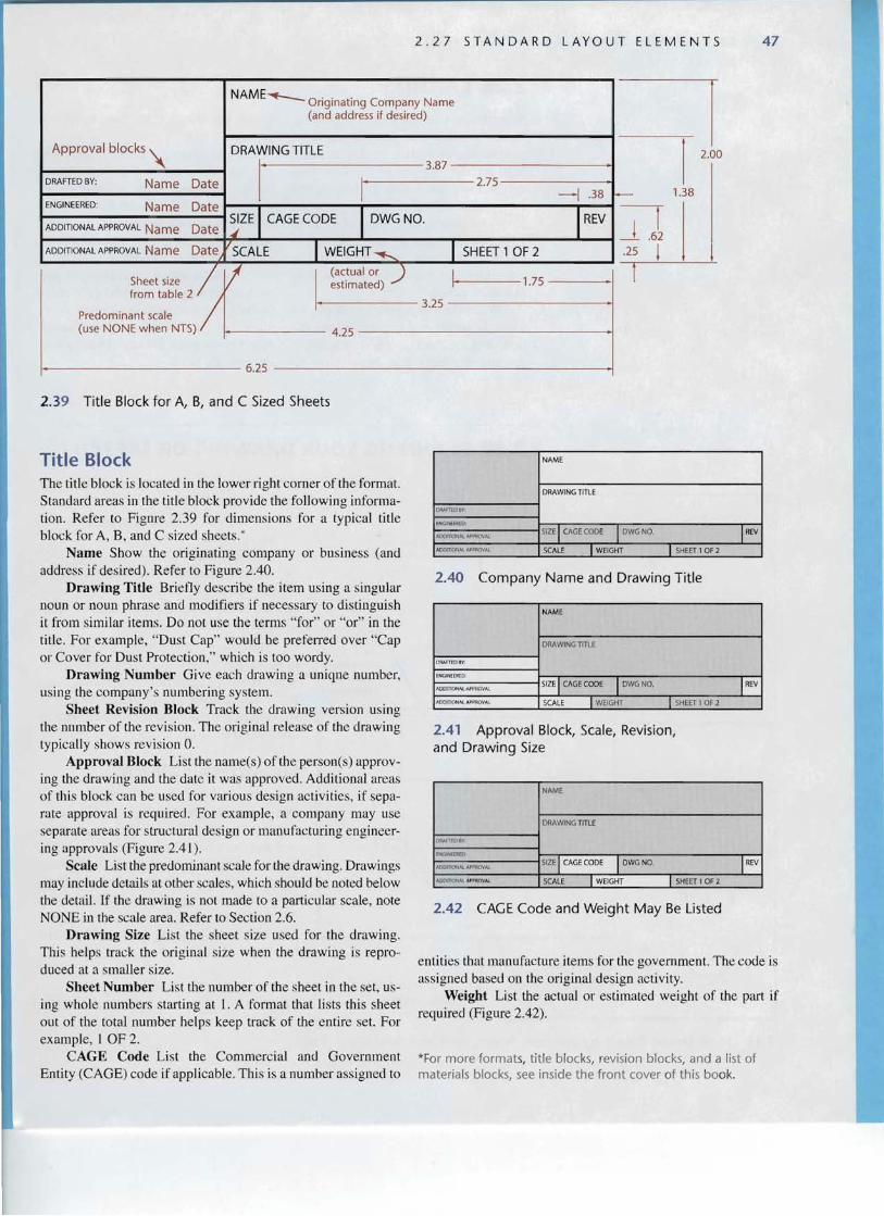
Title Block The title block is located in the lower right corner of the form at. Standard areas in the title block provi de the following informalion. Refer to Fignre 2.39 for dimensions for a typical title block for A, B, and C sized shee ts:
Name Show the originating company or bus iness (and address if desired). Refer to Figure 2.40.
Drawing Title Briefly descr ibe the item using a singular noun or noun phrase and modifiers if necessary to distinguish it from similar items. Do not use the term s " for" or "o r" in the title. For exa mple, "Dust Ca p" would be preferr ed over "Cap or Cover for Dust Protecti on," which is too wordy.
Drawing Num ber Give each drawing a uniqu e number, using the compa ny's numb ering system.
Sheet Revision Block Track the drawin g version using the number of the revision. The original release of the drawin g typically shows revision O.
Approval Block List the name(s) of the person(s) approving the drawing and the date it was approved. Additiona l areas of this block ca n be used for various design act ivities, if separate approval is requ ired. For example, a company may use separate areas for structural design or manufac turing enginee ring approvals (Figure 2.4 1).
Scale List the predominant scale for the drawing. Drawings may include details at other scales, which should he noted below the detail. If the drawing is not made to a particular scale, note NONE in the scale area. Refer to Section 2.6 .
Drawing Size List the shee t size used for the drawing. This helps track the origi nal size when the drawi ng is rep roduced at a smaller size.
Sheet Number Lis t the number of the sheet in the se t. using Whole num bers starting at 1. A format that lists this shee t out of the total number helps keep track of the entire set. For exa mple, I OF 2.
CAG E Code List the Commercial and Government Entit y (CAGE) code if applicab le. This is a numher assigned to
NAME
ORAmOll'l'
f NGlN.EFH D:
"OOl1'1ONAlIlJ'f'AOVAJ.
A DDmON "'- A ~o\l.
DRAWING TITLE
SIZE ICAGECODE IDWGNO.
SCALE I WEIGfIT I SHEET1 OF2
IREV
2.40 Company Name and Drawing Title
NAME
D!lAI TrD RY
I N(.iINH IlW .
A(XKl IONo\l."-W11OVA.l.
AOOI r lC\NA.L A;>Pfl lj\l A\.
DRAWINGTITLE
SIZEICAGECODE IDWG NO.
SCALE I WEIGHT I SHEET 1OF 2
IREV
2.41 Approval Block, Scale, Revision, and Drawing Size
NAME
DRAWINGTITLE
SIZE ICAGECODE IDWGN O. IREV
SCALE I WEIGHT I SHEET I OF 2
ORArTEOSV
ENGINH Rt:O
AODInoNAlAWl'lOVAI.
AoornoNAl A,Pr P,OIIA,
2.42 CAGE Code and Weight May Be Listed
entities that manu factu re items for the government. The code is ass igned based on the original design activity.
Weight List the actual or es timated weight of the part if required (Figure 2.42).
*For more formats, ti tle blocks, revision blocks, and a list of materia ls blocks, see inside the front cover of th is book.

48 CHAPTER 2 LAYOUTS AND LET TERING
2.28 LAYOUTS
A parti cular size sheet with a drawing bord er is called a layout. Using a CAD system, you may often be able to select from standard layouts or templates that set the sheet size limits, the border, and even the title block as the starting point for your drawing . Regardless of whether you draw by hand or use CAD or 3D modeling methods, you need to plan your sheet so that the information will fit and show clearly.
When sketching, your layout may be a simple border and title strip along the bottom of the sheet (or you may be using preprinted tablet s that have space to
record the sketch title, date, and other pertinent data).
When creating a 2D CAD drawing, you may use a drawing template showing the sheet and border and title block, perhaps using different templates or even software interface settings for different types of drawings, such as mechanical! manufacturing, architectural , or civil.
When creating a 2D drawing to plot from a 3D sol id model, you may use a layout space that contains different viewports that allow you to show different views of the same 3D model with a border and title block.
2.29 PLANNING YOUR DRAWING OR SKETCH
Ample space for dimensions and details
--- - - - t------
Too big for sheet. Leave more space notes and dimensions
Too small to show detai ls clearly
I
2.43 Show Details Clearly by Selecting Appropriate Scale and Sheet Size
When laying out a drawing sheet, you will need to consider:
• the size and scale of the object you will show.
• the sheet size. • the measurement system (units) for the
drawing. • (he space necessary for standard notes
and title block.
The object you are drawing is the "star" of the sketch. Keep the object near the center of the sheet. It should be boldly drawn, using thick visible lines. Make it large enough to fill most of the sheet and so that details show clearly (Figure 2.43 ).
Show Details Clearly Show small objects larger than their actual size to represent the details clearly. If the details are too small, switch to a larger sheet size and use a larger scale. You can also add details at a larger scale if necessary to show features that are smaller than the typical features of the drawing, If you add details at a different scale. label the view, for example, DETAIL A, and note the scale for the detail below it.

2 . 2 9 P LAN N I N G YOU R D RAW I N G 0 R 5 K ETC H 49
SHEET LAYOUT
Given drawing
To draw the part shown in the
given figure, se lect the sheet size, keeping in mind the size of the obj ect s. Show the part large enough to repre
Orient paper and tape down, if you find that
helPfUI~
8.5"
sent features clearly. 11" Use larger sheets for larger or more detailed objects. (8.5 x II" will he large enough for the part shown.) Add the border and title hlock to the sheet using the margin sizes specified in the standards. Refer to Table 2.2.
Determine the units ~~ ! ' ~
i Lightly blo k , in centerline
IV-Short dashes, not dbts
for the drawing. Will it he metric or
U.S. Customary (inches. feet and inches)? What system will he used to construct. manu facture, and inspect the actual ohject? Use that system of measurement for the drawing. Thi s part is iu inches.
Befo re you hegin drawing, determine the sca le at which the object will best fit on the sheet.
First, figure the available space within the draw ing border. For example the horizontal 8.5 x II" sheet with a .5" margin leaves 7.5 x 10". If you subtract space for a .375" title strip acro ss the bottom, it leaves 7.125 x 10" for the drawing.
Now, consider the size of the object. Will it fit on the sheet at full- size ? Half-size'? Do you need to enlarge it to show small features larger than actual size? The 12" gasket shown in the example will fit well at half- size on the 8.5 x 11"sheet select ed and still show the details clearly. Use typical scales when possible. Refer to Section 2.5.
Approximately center the object on the sheet. To do this, subtract the size of the scaled drawing from the available sheet space and use half of the difference on each side of the object .
One quick technique is to find the center of
the available space and lay out the drawing on each side of that centerline, Usiug CAD, you can easily move the drawing to the center of the sheet visually.
Lig t lv bloc in over II size to scale centering on lines
Sketch es do not have to be perfectly centered, hut plan ahead so the drawing isn't crammed in one corner of the sheet. Let your drawing: be the "star" of the page. Rernemher to leave enough space around your drawing for notes and dimensions. If you don't, you will run out of room and your layout will look crowded.
Lightly add details of the drawing. vn 0
--. 0 -
Add detai ls
Darken final drawing lines .
"
V-m -$ . ~Y' 1¥
fl Darken final lines and add title block
....--- TI P ------------, Scale When Using CAD Keep in mind that when using CAD you will create the object the size that it actually exists in real life. On the plotted sheet, when showing the drawing to scale, it is easy to try a few different scales and see which fits. You can always change the scale later if needed.

SCALING ANNOTATIONS AUTOMATICAllY USING AUTOCAD 2008
Iil!lAUloCAO 2008 · Nor FOR R£SAl E · [C;lP rog rom FiI.,lAuloCAO 2008\Sampl•. . . G]@[8] _ 0 x
f f," r
~ 77.7'3G. ~9.5'i 1 9 . 0.0000
~ lfl"tIU! 0l'NJW m...a
.1/""""1 o..u 1tlOn<H:
A
: " [ Ie ~<it \)ow lnW t f'2m\Ol 1001>
2f) O"lIt<lg ~ Amola6on v 'm' ...
tt
(A) Wh en plotted to scale 1/4 " = 1'-0" on an 8.5 x 11" sheet, th e text sho wing the dim ensions is clearly visible . Courtesy of Autodesk, Inc. © 2006-2001. All rights reserved.
You might thin k that di spl ayin g text in a CA D drawing is one of the easies t things to do. You ca n qu ickl y type in the text yo u want to di spla y an d se lec t the fo nt, height slant, and ro tatio n ang le. Th at part is ea sy. but anno tatio ns are useless if nob od y ca n read them.
Wh en you create drawings that will be plott ed on di fferent sized sheets or at di ffe rent sca les, siz ing the text can require a lot o f planning . Take the plot architec tural plan drawin g sho wn in Figure A for example . Wh en plotte d to scale 3" = 1'-0", the text showing dimen sion s is clearly visible . But wh en sho wn at one- twe lfth of that size, scale 1/4" = 1'-0", that same text becomes illeg ible.
Th e abili ty to reu se the sa me C AD da ta at different scales witho ut having to recrea te the dra wing is one of its big advantages ove r pen and paper drawings. Yet cumberso me workarounds were once necessar y to make legible text at different sca les. O ne workarou nd was have severa l diffe rent sizes of the same text , whic h the user wo uld turn on or off depe ndi ng on what d rawing sca le wa s used .
Now, AuloCAD 2008 soft ware provides a feature called annotat ion scaling . Here is how it works: Drawing o bjects that are co m monly used to anno tate drawings (provide text informat ion ) can have their annota tion pro perty turned on. Thi s a llows yo u to create one annotative object that displays a t different size s, based on sca le pr operti es .
In the AutoCAD soft wa re, object types that can have anno tative object properties incl ude Text , Mtext, Dimen sion s, Hatch es, Toler an ces, Mulrileaders , Leade rs. Blocks, and Att ributes.
1M! Annotation Object Scale LlJ ~
Object Scale List
1/4" = 1'·0" Add.. 3" =1'·0" 3/16" = 1'.()" Q.elele
0.25paper units =12 drawingunits
o !..ist allscales 101selectedobjects
o List scales QOmmon to all selected objects only
OK I I Cancel 1[ !:!.elp
(B) Using th e annotation scaling feature of AutoCAD 2008 software, annotative te xt can be made legibl e a t var ious scales . Courtesy of Autodesk, Inc. © 20 06-2001. All rights reserved.

PORTFOLIO ~
Lrl
o -' o u,
I<:<:
o Q..
1OII5.1KIU.,.....~ THIS PARTISPRODUCEDFROM AN ElECTR()Io,nC , AU ~N4"Da:NAl HOe. DATA fU PROVDEI)10 THEveooe. D1oVtENSl()NS -: IlWfJ'Io'lAUMIbS .......1OOel. SHOWN ARE FOt1REFB1ENCE. ANY OIlER DIMENSIONSJ. 1If.M(MAlJ, lOOlM)WlM1 4 ~' 'CIlJ''...-.ca $>¥oU. .. oe.1> SHOUlDBE-OBTAJl.lEOFRQI.'\THE MODB,. UIIIt""..... Ot.....
SEEASSEMBLY DIRECTIONS FORINSTRUCTIONSON SQUARING CHASSISASSEMBLY.
PROTOTYPE ONLY
UNRELEASED! FOR QUOTING OR
.~ 0§.. Q "o
;:,....
51 .... ::l (3 ..>i. u o
:0 <Ii ~ :;:;
1: ~
"0 C n:l.... Vl
~
"0 C ~
x u o
:0 ,... (5
'Vi's ~ n:l
01 C
' ~
os: Vl
01 C
' ~
~ "0 >, 0 - t::..0E ~ <Ii Vl ~ Vl o ~ <\J
Vlc <\J« 0:::
CHECK MRP SYSTEM FOR UPDATED BOM AND/OR UNLISTED PARTS & QUANTITIES.
ITEM PART NUMBER DESCRIPnON NO.
63224100 DRUM MODULE 61124290 2 CARRIAGE RU N~ER·RiGHT, M/CJ 61124291 CARRIAGERUNNER·LEFT, M/C33
4 21620101 ANGLE, RAILMOUNT·LEFT 21620102 ANGLE. RAILMOUNT-RIGHT 21226200
5 BULKHEAD- DRUMMODULE
21224200 CARRIAGE MIDDLEBULKHEAD B 61124820 FRONTCARRIAGE ASSY 9 21195301 3G SUPPORTBOX 10 61124690 CARRIAGE FRONT PANEL ASSY 11 61129170 HOOD WLDMNT·TOP· DRUM 12 HOO D, DRUM MODULE 13
21226501 61124691 CARRIAGERIGHTTOPCOVERASSY
14 61124692 CARRIAGELEFT TOP COVERASSY 15 21626210 WIRINGZ·BRACKET 16 21226502 HOOD·SIDE. DRUM MODULE 17 2122430J CARRIAGELEFTSIDEPANEL 18 21224300 CARRIAGERIGHT SIDEPANEL 19 21224302 CARRIAGE TOPCENTER PANELV2 ~Ih~ 20 rm&:l,Il!I'l6l.-.otl<. lOO "JCDlDtwl.taCtJ.~" Sof'TJ<l21626211 NEWDYNO WIRING BRACKET ...,.................
SCREW. 3/8-16xl-I/4-, BH·Fl NG 21 36582034 ae-. .....,... """""" tJlI . "' . CbosssAssemblyfor MC3,LQ , NO,Uo fWASHER.3/8".HARDENED,FLAT,sn22 36923100 ven:, I .
flONOt'.tC.AU'ItIlClt,o. CJ"UJlO: .. ..- II~
NUT.3/8· 16,NYLOCK23 36488100 24 SCREW,I/4·20xS/8",PH.TORX36561045
AUot.U.CDCHl.~~f'INoGI'OCAIIDOl!~"'''DM-''':;'''''Cl'Me''1 ~1IttlIlll()l1ilC.AlC)""CIlAMLtVCl"'!DAIC)ONll()I"fDK)tW~ AIC)I'II~_ 711 26890 "--=nD"'.«a.!'IICICSlIOOOfM.~~Ol!~....-u.~.,Ola.aolmDMI 50-011.Q04 3/8 NUT 1ON«1'faIOool1'eot<»~I'CIINl'r~_~-.x.I"" "'-"'~OI0w.0.R~fC.. OTtlCUi!I -....ol NC.1 ~ ...r
01 25

52 CHA PT ER 2 LAYOUTS AND LETTERING
~, • ...- .... IflOI "" 10 '1 .
a _1':;~~~ I ~ ~ "'c ""o!nocIioon2 _l ln~."' '''''''_~
.-. "IIC\OOWQIll<,OP£C1 llC.A "'j .om TCiX'l.,l'n"."'CIn 00 _ 1 ;C>r1 0I0ll ... ."... \It IN ~~ \If '" ""....-""" . ..._ t~ ...... t erl (eA) rJ.' tro. ..-.. HUENEIIl E RO....D TRAffl C CONlll:Ol PIPE SU.. 12 ,U <l5c ffi 1,11'1<" .", 1>0«)
~ro~s(40+~--B ~C.'''' · IlO '' ll.o.ec 1
CAlllGUA'S lIIUNIClPAL WAU R llCSTRler
o ....I
o u. A civil drawing showing approval blocks and engineers' stamp . Courtes y of Perlit er and Ingalsbee Consulting Engineers and
I- Callequos Municipal Water District. 0:::
o Q.,
lMNrON 50trLU
\1K :<Oft, M'NJA.fl}fPI "~f, fiff 1~"ilZf I I/&'fl ' ~O
0 8i.{3[iN» i".ctK rne; WI\\'Die V~.)l.fVW· l r r~'C, Cl~I'''' (,o,.A75~,O: J ~ZIJ ~~~/16" ~ to 7/8" FAllOl'N fO I:'i:' 1il;1erM,\f1l"~1\'.tt"
e ~NJ'O~·Art. O'f:ftl'Sfa~,w", ~.ViNI~ 74.\2·: 2-' X24 '
~ f'1' ;rro '.~>!JOV''''VI~'Y_
@ ~JMMlf p 2";11 X24" flJ1 74X24 VN'!
<D P1ff;;,lW;CDl~ . fJ(, 8X13 a.~?C'..W F'/oiLWI mfl; VINI1. ff:Nt2, ~/8" ,7, ~113"..i.!'[t,I!t,OC' 7..\X2.,
l'~r11'R'N1(j1ll:[;l'Il~Mlt.H'""r&r,'~
0 to. I>. s to.Jj<. -ttlII A ~ "'4 IIZ" ""fiA .~ WO(!.i1 (efoV eXl,f1OI! fI.'N tT.!
<D "{;Mt,,~'f rOOR :x:}'WLUvir ;l'~ I
0 t,'!: tftX~:m 5'~..J.SlZt 'lfNf'CJJ'1U L'ot 11·\WIJl 'fW~!-fl'W.vm IoKJ1l:Pill'i!1.J?( "C<'l1('N .
IC()1(; OIlffi-vrVOCl1 furClfIAI1C Q'!;/,fR ( 4) W'VOi'IS iNillf' f "'1'(.fW''if~r>: 0-"'<~'" PI
0 I~ m~'I(jI(Il00' :M.l1H\\' "( oc.cf.l Qftf.(: ' I.!M f INcr.• lOV1\Jr rc lj" :;ffi~\"I"
0 'Xfl;f1OI!I!OLIU)b ~,~ePNc \ t JYL. '1I."nf'.'" L~I f~O'>,[lr 'Mln: K%'i; -.,'1~~O (V'.7I;f;NC,j vex-X)
0 r;xlH'ICr. OGWI.' vr.·Anu"" VIH'~"'t .\.~I '·W.EF':.. V~IVl. I,Hn" ' f!fN, rW If0 : ,1 I( t " lOB f!1'>.(,iWQb
0 loot) INltRi - , t70Cf' JI'JCHF','<l: 11'M"I'fifOa,,-,
0 fr;IJ;H A-iIiB 'A/X»°iXrtr~M fUl.;lI', W FINI'+! ro oc [;l''V1~I/otO
0 F",."246B '!ilJVJ :xr.fl V0C9 ,(UO,", .r,f 'INI'>'rOll!: [;l'11'~ \VEO
~ '0 ' .. ~. Window and Door schedules are used in architectural drawings to specify the type of window or door, rough opening size, rnanatacturer and othe information. Courtesy of Frog Rock Desiqn, LLP.

53
KEY WORDS Station Poin t
Plane of Projection
Projectors
Piercing Points
Perspecti ve Projection s
Parallel Proj ect ion s
Orthog raphic Projecti on s
Oblique Projection
Multi view Projection
Drawing Lines
Letterin g
Measurem ent Systems
Sca le
Title Blocks
Thi ck Lines
Thin Lines
Freehand Line
Co nst ruc tion Li nes
Drawing Scale
Scales
Engi neers ' Sca le
Deci mal Inch
ArchitectsScale
Font
Ser if
Ital ic
Rom an
Sa ns Serif
Guidel ines
Verti cal
Inclined
Kerned Pairs
Media
Sheet Sizes
Zo ne Numbers
Na me
Dra wing Title
Drawing Number
Shee t Revisiou Block
App roval Block
Scale
Drawing Size
Sheet Numb er
CA GE Code
Weight
Layout
K E Y W 0 R D S
CHAPTER SUMMARY Now that you have comp leted this chapter you should be able to:
o Unde rstand the basic principles of projection used in draw ings ,
o Dem onstrate the line we ights (thickness) and types (dashed or so lid) of lines used in the alphabet of lines that specify meaning in techn ical drawings.
o List the two main systems of measurement used on drawings.
o Use different types of sca les to make measurem ent s. • Note the seale for a drawin g in the title block. Pape r draw
ings are sca led before they are drawn. CAD draw ings are scaled when they are to be printed .
• List the adv antages of seve ral different drawin g medi a and the qualit ies that distin guish them .
o Add legibl e and quick to produce notes and dimensions to sketc hes using uppercase letters draw n by hand .
o Lay out a sheet and rill in the infor ma tion in the title block using standard letter shapes.
REVIEW QUESTIONS I . Draw the alphabet of lines and lahcl eac h line. 2. Which architects ' sca le represent s a size rat io of I :24'!
Which metr ic scale represent s a half size'! Which en gineer s' scale would be used for full size?
3. Which scale type is the only one to use fraction s of an inch?
4. Wh at are the main advantages of polyester film as a drawing media?
5. What are the four standa rd types of projections? 6. Wh ich draw ing lines are thick? Whi ch are thin? Which are
very light and should not reproduce when copied? 7. What font provides the shape of standard engineering
lettering? 8. Describ e the characteristics of good freehand lettering. 9. Wh y should guide lines be used for letterin g?
10. Lis t the standard items foun d in a title block.

54 CHAP TER 2 LAYO U TS AND LETT E RING
EXERCISES
Drawing Exercises
Practice you r skills for making measurem ent s, layin g out drawing sheets, and forming ueat standard lett erin g with these drawin g exerc ises .
Th ese problems arc designed to fit eas ily on a shee t. (See the ins ide front cover o f this book or the form provided on the Web as a pdf file that you ca n print to ske tch on) . Draw all co nstruction lines lightl y, using a hard lead (41-1 to 61-1) , and all requ ired lines dense black with a so fter lead (F to 1-1). Draw your co nstructio n lines lightly so that they do not need to be erase d.
In exercises 2.1-2 .3 you will pract ice measuring. and in Exe rcises 2.4-2.6 you will practi ce draw ing layo uts.
Exercise 2 .1 Measure the lines shown above and list their length s usin g mi llimeters. List the inch measurem ents for each in sq uare brackets r[ to the right of the millimeter measurem ent.
Exercise 2 .2 Measure the lines show n above and draw them at Scale I :2, Scale 2: I, and list their sca les below them using the form Scale: X :X.
Exercise 2. 3 Measure the overall interior dim ensions of your roo m. Letter the measured length neatl y in the first co lumn as shown in the exa mp le. In the second co lumn list how long you would draw that line at a sca le of 1/4" == I'. third column at 3/~" == I', fourth co lumn at I" == I ', fifth co lumn at I :100 metri c scale ( 10 111m == I meter )

BASE. I PUBLICK . J OHN Q. I I' ; I' I 8-1-02 J A-6 I 3 Exercise 2.4 Create the layout for and 8.5 x II" sheet as shown at left.
INSTITU T E OF T ECHN OL OGY I F IXTURE BRACKET I S EAT 25
SCALE: 1/1 I DAT E.: A UG. 1.2002 I DRAWN BY : ..J O SE PH E . BLOUGH ,JR. I S H EET 2 Exercise 2.5 Create the layout for the 210 mm x 297 mm sheet shown at left.
Exercise 2. 6 Design a title block and layout for a C-sized sheet. Creat e a name and logo for your compauy. Use an attractive but .legible font for the titles on your layout. If assigned, design a special north arrow to be used on your drawings.
Lettering Exercises
Layouts for lettering problems are given in Exercises 2.7-2.1I. Draw complete horizontal and vertical or inclined guide lines very lightly. Draw the vertical or inclined guide lines through the full height of the lettered area of the sheet. For practice in ink lettering. the last two lines and the title strip on each sheet may be lettered in ink, if assigned by the instructor. Omit all dimensions.
Exercise 2 .7 Letter the words to your favorite song, joke, or inspirational quote of 50 word s or more. Use 1/8" tall UPPERCASE engineering lettering. Cent er the word s near the middle of the shee t. Make sure to leave a row of space between each row of lettering. Make sure that the subjec t you choose is professional and appropriate.

2 L AYOUTS AND L ET T ERI N G
!
y -
y I c a
j d
] d
-h rn j 5
- 1\1 _
=
ETNE::t rA.T£l 1
- WAY:-tvl INlMIZ8
.L'---L--- --, =]
I ----i"'---~------__,
2: "~ ====~
ITM n-EL 8ME-:: B EA'iZY -~-X E
I __J L,tIT"H~Y_WB.E.E l-UN Bl
J _....=:=I ELAJ WH t:z:=:::WAZi I I
• SHEET 3 f I
I..
CHAPTER
p
i=== 9
_ , I j
1 ~----rj ::....J..J ~ _-j=----=~
t -~~ V ~ I..... =" '{IV x
K I
DAT E
-"-- - - ----''----
+------,.----------..;~ ...,--- -SH EET I : 1
Exercise 2.10 See instruc tions for Exercise 2.8.
Exercise 2.8 Layout sheet inclined guide lines and fill in vertical or inclined capital letters as assigned. For decimal-inch and millim eter equivalents of given dimen sion s. see inside back cover.
SEC T ION I : NAM E
- - - - - - - "0 '0
as shown. Add vertical or Exercise 2 .9 See instructions for Exercise 2.8.
S ~ CTtON I NAM E ___~-l
--->SHEET'" r
".
l .
S - - -, - -- - ---'
I
TE SECTION = , N AME L' ~ I
SHEET 4
2 4 d;
.----- - - - - - ------ --,b 6 -' rz- - - - - 8__ 9 . 0, --1
Exercise 2. 1 1 See instructions for Exercise 2.8 .