chapter v mining methods and coal processing...
TRANSCRIPT

131
CHAPTER V
MINING METHODS AND COAL PROCESSING TECHNOLOGY
5.1 INTRODUCTION
Mineral exploitation in which all extractions are carried out beneath the earth’s surface
is termed as underground mining. Underground mining methods are employed when the depth
of the deposit, the stripping ratio of overburden to ore (coal or stone), or both become
excessive for surface exploitation (Hartman and Mutmansky, 2002). Underground mining
method selection is one of the most important decisions that mining engineers have to make.
Choosing a suitable underground mining method to extract a mineral deposit is very important
in terms of economics, safety and productivity of mining operations (Alpay and Yavuz, 2009).
Pabedana coal mine is an underground mine operated by government and at present is
administered by a private company. Exploitation coal from Pabedana area was started in 1977
and proven coal reserves are around 41 million tons. Economically extractable seams are
designated d2, d4, d5 and d6 and are situated 2400-2505 meters above MSL. Long wall
mining method has been adopted at Pabedana for extraction of coal.
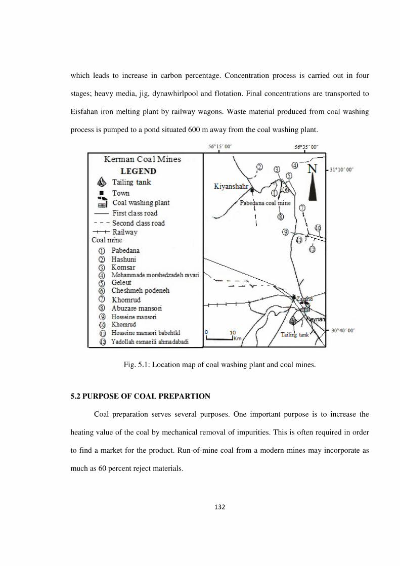
Extracted coal is transported by trucks to Zarand coal washery, which is 65 km south
of Pabedana coal mine (Fig. 5.1). In Zarand coal processing was commenced in 1978 with a
capacity of 2 million tons of raw coal with 61% production efficiency. Zarand coal washery is
one of the biggest coal concentration plants in southwest of Asia. The design of coal
processing plant is influenced by a number of factors including coal characteristics, market
requirements, local infrastructure and regional preferences (Kamall, 2001). In this plant the
coal concentration process involves, coal washing and decreasing ash-content and impurities,
132
which leads to increase in carbon percentage. Concentration process is carried out in four
stages; heavy media, jig, dynawhirlpool and flotation. Final concentrations are transported to
Eisfahan iron melting plant by railway wagons. Waste material produced from coal washing
process is pumped to a pond situated 600 m away from the coal washing plant.
Fig. 5.1: Location map of coal washing plant and coal mines.
5.2 PURPOSE OF COAL PREPARTION
Coal preparation serves several purposes. One important purpose is to increase the
heating value of the coal by mechanical removal of impurities. This is often required in order
to find a market for the product. Run-of-mine coal from a modern mines may incorporate as
much as 60 percent reject materials.
133
Air pollution control often requires partial removal of pyrite with the ash to reduce the
sulphur content of the coal. Ash content often must be controlled to conform to a prescribed
quality stipulated in contractual agreements. Because of firing characteristics, it is often as
important to retain the ash content at a given level as it is to reduce it.
Freight savings are substantial when impurities are removed prior to loading. Finally,
the rejected impurities are more easily disposed off at the mine site remote from cities than at
the burning site, which is usually in a populated area.
5.3 MINING METHOD AND EQUIPMENTS
Pabedana coal mine is an underground mine having 25 stopes. These stopes are active
in workable coal seams, and the number of stopes in different coal seams are: 19 in d2 seam; 2
in d4 seam;1 in d5 seam and 3 in d6 seam. d2 seam has the maximum number of mining stopes
with production of 1,02,000 tons/year.
In the Pabedana coal mine, the average coal production is around 174400 ton/year
which comes from different coal seams namely, d2=1,02,000, d6=30,000, d4=24,000 and
d5=18,000 ton/year. Height of the tunnels varies from 2.5 to 4 m in underground paths. Tunnel
dimensions depend on kind of tunnel and vary from 5.6 to 14.8 m2 (Fig. 5.2). Wall and roof of
drilled tunnels are supported by metal panels, concrete and timber. Supporting of mining
stopes are implemented by wood pillars, timbering and hydraulic jacks.
Inclination of coal seam is the main parameter for determining the type of wall face of
mining stopes. Therefore, for extraction of coal reverse benching method is employed for
extraction of coal from seams having dip more than 40 degrees whereas longwall mining
method is selected for seams with less than 40 degree dip. Classical longwall method has been

134
used rather than mechanized method for production, because the field is often subjected to
severe tectonic movements (Hindistan et al., 2010).
Extraction by longwall mining is an almost continuous operation involving the use of
self-advancing hydraulic roof supports, a sophisticated coal-shearing machine, and an armored
conveyor parallel to the coal face. Working under the movable roof supports and riding on the
conveyor frame, the shearing machine cuts and spills coal onto the conveyor for transport out
of the mine. The major advantages of the longwall mining method include its suitability for
mining at greater depth, higher recovery, and higher production rate compared to room and
pillar method (Scott et al., 2009). In these days the underground mining practice involves
lively mobile machineries, which drastically simplify preparatory and development operations
of stoped excavation, boost mining works, and minimize hand-labour due to the overall
mechanization (Oparin et al., 2008).
In the Pabedana coal mine, where longwall mining method is practiced cutting
machines such as oral and temp machines are employed; the cutting machines increase
extraction efficiency by 4 times. Oral machine consists of a blade of 180cm length and 15cm
thickness. Oral machine is used for cutting the lower parts of coal seam, so that due to gravity
force the roof coal automatically falls into the open place from where it is collected. Temp
machine contains large and strong drill bit which has the ability to rotate and move forward
during cutting process of mining stope. Extractions by temp machines are not economic owing
to the presence of fractures and joints in coal seams and lower coal reservoir volume.
Working cycle of mining stope includes: (1) drilling with hand perforator, (2)
detonator operation periodically , (3) explosion of wall face, (4) periodic tunnel ventilation, (5)
loosing operation, (6) survey of face wall, (7) loading of load-haul-dump (LHD) loader, (8)

135
installation of metal panels in roof and walls of tunnels, and (9) timber support with wood
pillars in between panels.
5.3.1 Longwall mining process
The longwall mining system is comprised of a shearer machine, articulated face
conveyor (AFC), and a system of longwall shields. The shearer machine cuts coal from the
seam and on to the face conveyor to be transported to the surface. The shields are utilized to
support the immediate roof and protect the employees and equipment from rock strata above.
A system comprised of rubber conveyor belting suspended on steel structure, transports the
coal from the continuous miner units and longwall units to the surface, so the coal can be
prepared and processed for shipment to the customer. Through a series of physical and
processes, coal is sized to specification. Non-coal material, such as sandstone and shales from
the surrounding geology, are removed from the mined product. This process is often referred
to as "cleaning" to ensure the highest quality coal for coal washing plant.
Coal can be mined by underground or surface methods depending on the depth and thickness
of the deposit (Fig. 5.3).
The environmental impacts of mining vary depending upon mining methods employed,
specific deposit characteristics, coal and rock strata chemistry, and the geography of the
region. Figure 5.3 illustrates various methods of mining coal. Giant draglines are used to
remove coal in many coal mines.
In some of regions, small holes are drilled through the overburden (dirt and rock above
the coal seam) to the coal seam. Each is loaded with explosives which are discharged,
shattering the rock in the overburden. Giant power shovels or draglines clear away the
136
overburden until the coal is exposed. Smaller shovels then scoop up the coal and load it onto
trucks, which carry the coal to the preparation plant.
5.3.1.1 Jackhammer and Perforator
Tunnel boring machine (Picker) is used for extraction of coal. Drilling machine
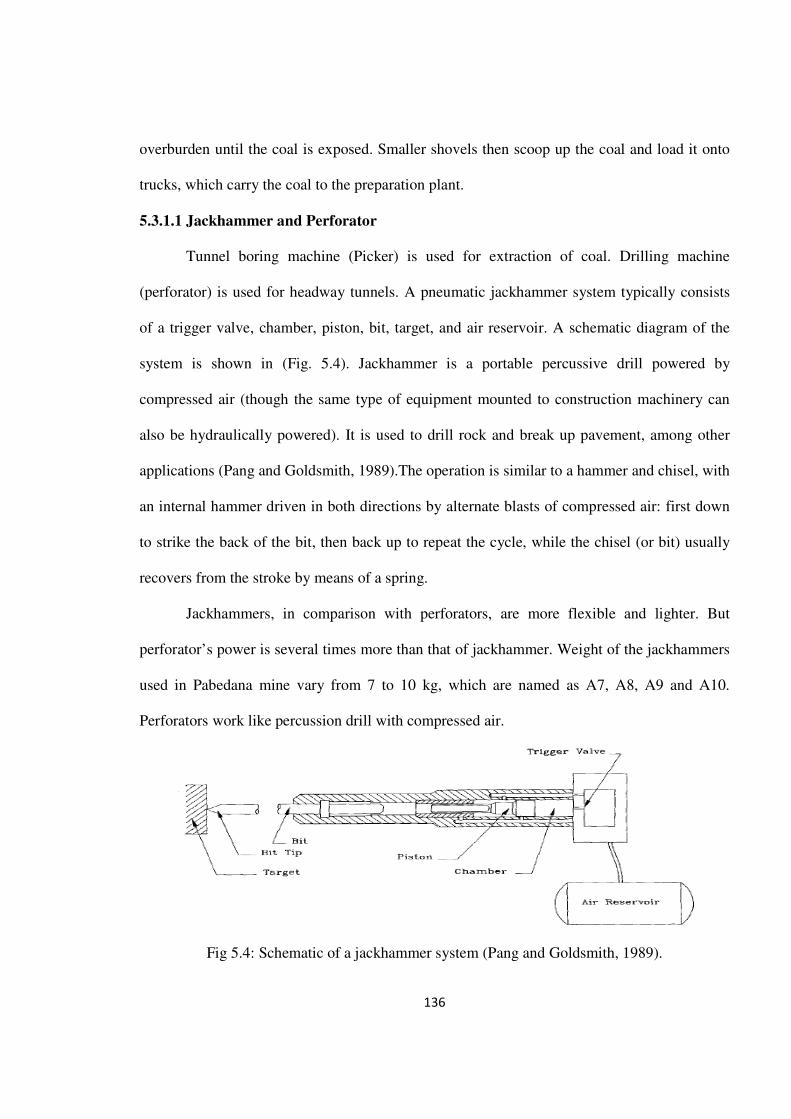
(perforator) is used for headway tunnels. A pneumatic jackhammer system typically consists
of a trigger valve, chamber, piston, bit, target, and air reservoir. A schematic diagram of the
system is shown in (Fig. 5.4). Jackhammer is a portable percussive drill powered by
compressed air (though the same type of equipment mounted to construction machinery can
also be hydraulically powered). It is used to drill rock and break up pavement, among other
applications (Pang and Goldsmith, 1989).The operation is similar to a hammer and chisel, with
an internal hammer driven in both directions by alternate blasts of compressed air: first down
to strike the back of the bit, then back up to repeat the cycle, while the chisel (or bit) usually
recovers from the stroke by means of a spring.
Jackhammers, in comparison with perforators, are more flexible and lighter. But
perforator’s power is several times more than that of jackhammer. Weight of the jackhammers
used in Pabedana mine vary from 7 to 10 kg, which are named as A7, A8, A9 and A10.
Perforators work like percussion drill with compressed air.
Fig 5.4: Schematic of a jackhammer system (Pang and Goldsmith, 1989).
137
Perforators used for drilling wall faces and raises, are of different weights; 12, 14, 16,
18 and 22 kg. Diameter of drilling bit is 3.2cm and mode of drilling is rotary-percussion (Fig.
5.5). There are bigger sized perforators which are used for drilling face wall. These perforators
consist of a telescope tripod which is attached to perforator. This device works with
compressed air. The tripod provides an appropriate saddle for drilling and reduce angle of
deviation of the drilling bit (Fig. 5.6).
5.3.1.2 Temp (coal cutting machine)
Tunnel boring machines are utilized for mechanized tunnel driving in all geological
and all environmental conditions. Temp machine is one such machines which is used for
cutting coal in longwall mining method. Temp machine used in Pabedana mine is made in
Russia and weight 7 tons. It is composed of 7 heavy electromotors. Temp machine consists of
a fixed cutting crown and a mobile cutting crown. Cutting crown can cut foot wall section of
mining stope and mobile cutting crown can cut coal seams upto a high of 2.5m (Fig. 5.7). It is
employed in stopes having 40 to 50 degree dip and resistant hanging wall rocks.
5.3.1.3 Raise boring machine
For decades, raise boring has been an accepted method for the installation of
production and ventilation shafts and ore passes for mines. It is also a widely used technology
in infrastructural projects for tunnel ventilation or surge shaft in hydro-electric power projects.
Raise boring machine is similar to perforator and both are used for face drilling. Raise boring
machine is used to drill raises of higher diameter. Due to its heavy weight, it is less frequently
used in Pabedana mine. Raise boring machine is inapplicable for raise boring more than 8m
length (Fig. 5.8).
138
5.3.1.4 Jumbo drill
Jumbo drill works with compressed air and hydraulic power. This machine has ability
to drill holes in wall face upto 3m deep in 1 to 3 minutes time. The performance prediction of
the jumbo drills is very important for the cost estimation and planning of the tunnel projects.
The performance of jumbo drills mainly depends on machine parameters, operational
variables, intact rock properties and rock mass characteristics. It is known that, if the intact
rock properties are approximately same, drilling performance of jumbo drill depends largely
on the discontinuities in the rock mass (Kahraman et.al., 2006). Jumbo drill is installed on
chain belt and transmits along wall face route. Drilling bits are studded with industrial,
diamonds. hence, it is suitable to drill hard rocks. There are three hydraulic jacks in both sides
and back side of Jumbo drill. Hydraulic jacks have an important role in stabilizing the Jambo
drill and they reduce the angle of deviation of the drilling bit. Therefore, drilling operation by
Jambo drill is more appropriate than other drilling machines (Fig. 5.9). One of the
disadvantages of Jumbo drill is that it consumes excessive oil during drilling process. Hence, it
is uneconomic and at present this drilling machine is occasionally used in Pabedana coal mine.
5.3.1.5 Hydraulic jack
Hydraulic jacks are used for supporting tunnels. They can withstand 24 tons of loads.
If pressure is more than standard limitation on these jacks, they have stability against
pressures, because of these Jacks contain fine shots that prevent damage to jacks (Fig. 5.10).
The length of the Jacks are variable from 50cm to 2.5m and depends on thickness of coal
seams. Hydraulic jacks range in weight from 60 to 80 kg. Hydraulic jacks are widely used in
inside extraction stopes while working with Oral machine. Hydraulic jacks are best suited for
coal beds having a thickness of more than 80cm and maximum 35 degree dip. One of the
139
advantages of these jacks is consumption of less wood in stopes which inturn leads to
increasing safety coefficient in extraction tunnel.
All longwall mines employ preventative maintenance. It is one of the largest sub-
operations at any mine, and proves effective in that, when less attention is paid to
maintenance, more faults occur. The optimum level of planned maintenance is difficult to
determine because not all failures are age-related (Bongers and Gurgenci, 2008).
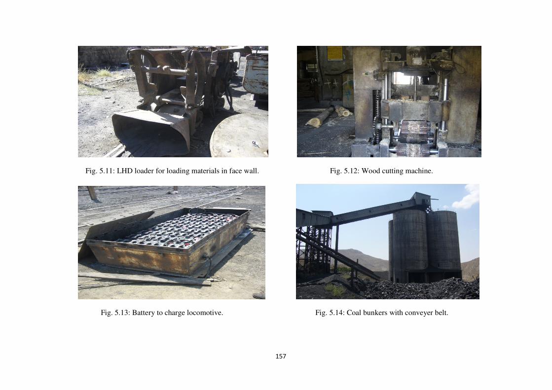
5.3.1.6 LHD underground loader
A Load-Haul-Dump (LHD) is a machine which has been widely used in underground
mines or tunnel construction sites. Pabedana mine loading machines are made by Atlas Copco
Company, Sweden. This type of loader is used for loading coal at wall faces. LHD machines
have three functions; loading, carrying, and dumping the coal. Generally, the scooping task is
carried out as follows: the bucket, which is located in front of the LHD body, is pushed into
the coal pile and the coal is scooped by lifting the bucket. Then the LHD is moved to the
dumping point (Takahashi et al., 2004). Operation system performs as loader spade and pours
coal to the loader bucket. Loader bucket is situated at the back of loader. Volume of loader
bucket is 200 lit and these loaders work using compressed air (Fig. 5.11). There are two keys
on Atlas Copco loaders, one of them is utilized for transportation system on the rail and
another for movement of the loader spade. The literature studies revealed that the highest
number of fatalities associated with roof bolter, LHD, and longwall are attributed to “Working
under unsupported roof”, “Failure of management to provide safe working conditions”, and
“Failure of mechanical components”, respectively (Kecojevic and Md Nor, 2009).
140
5.3.1.7 Wood cutting machine
The main task of carpentry is the preparation and development wood to support mining
stopes. Prepared wood support columns have different sizes that depend on tunnel space and
stope size. Wood cutting machine can cut wood in three rows having 3m×25cm size (Fig.
5.12). Another application of wood in the tunnel is to align temporary rail line.
5.3.1.8 Locomotive charge workshop
Locomotives that have not been fitted with charger is taken to the locomotive charge
workshop for battery charging, whenever needed. In order to charge 8.5 ton locomotive, 60
batteries fitted in a battery box are needed (Fig. 5.13). For 4.5 ton Locomotives, battery box is
fitted with 40 batteries. Each battery after charging yield a maximum charge of about 2.5 V.
For 4.5 ton locomotives 90-100V current is needed. These batteries charge during an hour and
provide energy for working 8 hours (1 shift). Life of each battery is about 3 years when used
in 3 shifts of 8 hours each per day. Right now, 3 locomotives with 8.5 ton weight and 10
locomotives with 4.5 ton weight are working in Pabedana coal mine.
5.3.1.9 Coal loading cycle
LHD loaders discharged extracted coal to tipper wagons. These wagons discharge coal
on to conveyer belt. Conveyer belt is 200 m in length. Coal is discharged through the funnel to
the conveyer belt and is transferred to four coal bunkers (Fig. 5.14). During transport by
conveyer belt, extra material (wooden pieces, other non-coal material) from mining stopes will
be removed manually. Coal stored in bunkers is loaded to trucks to be transported to Zarand
coal washing plant.

141
5.4 COAL WASHING TECHNIQUES AND EQUIPMENTS
Coal washing is a process by which impurities such as sulfur, ash, and rock are
removed from coal to upgrade its value. Coal washing processes are categorized as either
physical cleaning or chemical cleaning. Physical coal washing processes, which involve
mechanical separation of coal from its contaminants using differences in density and these
processes are commonly used now-a-days. Chemical coal washing processes are currently
being developed, but their performance and cost are undetermined at this time. In Zarand coal
washing plant, coal cleaning are based on physical process.
Two physical coal washing, processes are adapted:
(i) Separation based on differences in relative density (RD) between coal and associated
mineral matter; pure coal has an RD of ~1.3 and associated mineral matter commonly has an
RD of >2.2
(ii) Separation based on differences in surface properties between coal and associated mineral
matter; coal is hydrophobic, whilst associated mineral matter is generally hydrophilic.
Other separation methods, which include magnetic, electrostatic, chemical or
biological coal-cleaning processes, have also attracted considerable interest but, in general,
these have yet to achieve commercial viability (Kamall, 2001).
During cleaning process, generally 30-50% of pyritic sulfur and approximately 60% of
ash-forming minerals (residue left after coal has been burned) will be removed (Strickland
et.al., 2008). Coal washing plant composes of four main units, including feeding unit, main
building, drier building, storage building and loading building (Fig. 5.15).

142
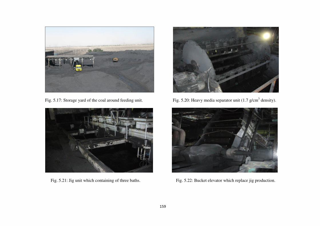
5.4.1 Feeding unit
Feeding unit of coal washing plant receives from Pabedana coal mine. An amount of
1,00,000 tons of raw coal with 36% ash enter the feeding unit. When trucks arrive to coal
washery, coal from each truck is sampled. Then the loaded trucks enter the feeding unit.
Sampled coal is dispatched to quality control for determining ash content (Fig. 5.16 and 5.17).
Coals from trucks are directly discharged into tanks and conveyer belts transfer the
coal to storage building. In the storage building 10 reservation tanks exist for each line with
capacity of 700 tons of raw coal. Operation capacity is reduced due to sticking of coal to tanks
walls. After the storage of each line, plant feed is moved to main building by conveyor belt.
5.4.2 Main building (Coal washing process)
Coal washing unit is housed in main building, where the coal is washed at five stages,
viz. (i) Heavy media, (ii) Jig, (iii) Dynawhirlpool, (iv) Spiral and (v) Flotation stages. In these
stages coal is washed and separated according to grain size viz., (+18mm), (+0.5-18mm),
(+0.15-1mm) and (-0.5mm) (Fig. 5.18).
رشيپذ دانيم

143
Fig. 5.18: Processing of coal washery in Zarand coal washing plant.
144
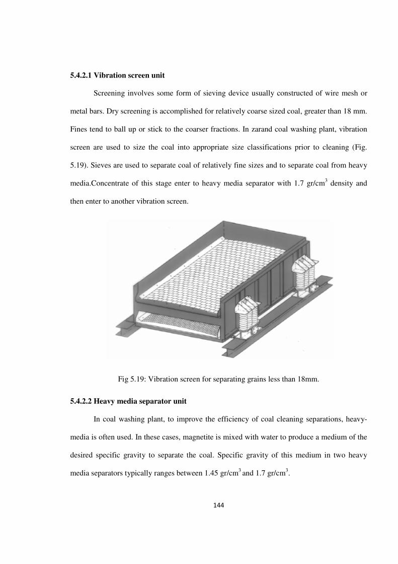
5.4.2.1 Vibration screen unit
Screening involves some form of sieving device usually constructed of wire mesh or
metal bars. Dry screening is accomplished for relatively coarse sized coal, greater than 18 mm.
Fines tend to ball up or stick to the coarser fractions. In zarand coal washing plant, vibration
screen are used to size the coal into appropriate size classifications prior to cleaning (Fig.
5.19). Sieves are used to separate coal of relatively fine sizes and to separate coal from heavy
media.Concentrate of this stage enter to heavy media separator with 1.7 gr/cm3 density and
then enter to another vibration screen.
Fig 5.19: Vibration screen for separating grains less than 18mm.
5.4.2.2 Heavy media separator unit
In coal washing plant, to improve the efficiency of coal cleaning separations, heavy-
media is often used. In these cases, magnetite is mixed with water to produce a medium of the
desired specific gravity to separate the coal. Specific gravity of this medium in two heavy
media separators typically ranges between 1.45 gr/cm3 and 1.7 gr/cm3.

145
The incoming raw coal is separated at 1/4 inch on an inclined screen. The “overs”
proceed to a flat “prewet” screen, where the fine dust particles are sprayed off from the +1/4-
inch coal. This increment is discharged into a heavy-medium vessel or bath, where the refuse
(residue) is separated from the coal. The refuse is discharged to a “refuse rinse” screen, where
it is dewatered. The refuse (residue) having density of more than 1.7 gr/cm3 contains
impurities (waste material) and is sent out of the system (Fig. 5.20). The slurry contains fine
coal (less than 1/4 inch; density less than 1.7 g/cm3) and floats on the heavy medium of
magnetite. It is pumped to another heavy media 1.45 gr/cm3 density separator (Fig. 5.19).
Heavy media separator consists of shaft-mounted steel drum containing an interior
fixed magnet. The cylinder rotates within a vessel containing coal slurry and magnetite.
Retrieval of solid magnetite from the slurry is by virtue of the magnetic quality of the
magnetite and the magnetic field within the drum. The slurry recovered by virtue of the
magnetic separation is sent to centrifuge and cyclone to recover finer clean coal.
Key factors in the operation of any dense-medium system based on magnetite are the control
equipment and the efficiency of magnetic recovery for recycle.
5.4.2.3 Magnetite separator unit
The magnetite separation of sulfur and ash from coal is based on the difference in the
natural magnetic properties of coal and its associated mineral impurities. Most of the sulfur-
bearing and ash-forming minerals in coal are paramagnetic and can be separated from the
remaining diamagnetic material. Magnetite is a very heavy mineral that gives the suspension
properties similar to a true heavy liquid.

146
5.4.2.4 Jig separator unit
The Jig is relatively low cost, simple washing system generally considered efficient for
coals that are relatively easy to clean. Jigs yield 75-85% coal at about 34% ash content. The
Zarand coal washing plant consists of OM-18 model Jig. Feed of the plant is divided into two
parts of grains of sizes of > 18mm and <18mm. Grains of > 18mm size is transferred to
primary vibration screens and the grains of < 18mm size are fed to Jig canel. At the bottom of
this Jig channels bar screen is provided which separates soft grains (1mm) of coal feed. A
sieve bend is situated before the Jig separator for sorting grains of 1 to 18 mm size. Materials
on sieve bend, which is considered as a feeding, enter the Jig circuit. In the sieve bend, grains
between 1mm to 18mm size pass from the mesh. Soft grains enter to hydroclassifier where its
overflows are passed to flotation and underflow is returned to the primary vibration screen.
Jig separator is composed of three baths where water under each bath is made to
fluctuate by special mechanism piston, diaphragm or compressed air. Number of fluctuation
ranges from 40 to 300 times per minute. In this part grains on the screen are classified
according to the density. Density control is carried out by floatation body located in the jig bed
(Fig. 5.21). In a jig, the column of water is maintained in a constant up-and-down movement
by means of flow of air. Clean coal particles are carried to the top of the jig by this motion,
while heavier refuse particles sink to the bottom. Jig washing is still widely perceived as a
simpler, lower-cost option than dense medium separation and a range of improved jigs has
continued to find wide application in Germany, India and China.
Density of these three baths respectively are 1.7, 1.45 and 1.1, g/cm3. Overflow of each
bath is poured to the next bath. In the first bath the underflow material (waste material) goes
out of the system. In secend and third baths the underflow material goes out of system and
147
conduct to another jig (contorl jig). Overflow of the third bath is transferred to reservoirs
which are called bucket elevator.
A sieve bend is situated before the jig separator for sorting grains 1 to 18 mm size.
Materials on sieve bend, which is considered as a feeding, enter to jig circuit. In the sieve
bend, grains between 1mm to 18 mm size is passed from mesh. Soft grains enter to hydro
classifier where its overflows is passed to flotation and underflows is returned the primary
vibration screen.
5.4.2.5 Control Jig unit
Control Jig is composed of three units and its work is similar to primary Jig. Baths size
of control Jig is smaller than the primary Jig. Underflow of first bath as a waste material pours
out of the system and the overflow of the second and third baths is transfered to
Dynawhirlpool separator. Second and third baths production is 17 ton per hour. Overflow of
third bath as a concentration is transfered to bucket elevator (Fig. 5.22).
5.4.2.6 Dynawhirlpool separator unit
Dynawhirlpool separator unit is added to the present coal washing plant equipments.
This unit has the capability of washing grains which cannot be recovered from jig separator
and flotation system. In fact, it is a type of gravity system which works with heavy media.
Dynawhirlpool circuit gets its feed of grains from second and third baths of the control jig.
The main section of dynawhirlpool separator is composed of vacant cylinder which can be
inclined to an extent of 15-45° and the diameter of this cylinder varies from150 to 600 mm
(Fig. 5.23).
148
One of the advantages of this separator is that only heavy media needs to be pumped
into system whereas the machine feeding in provided by gravity pressure, therefore
operational charge is reduced.
5.4.2.7 Spiral separator unit
In coal washing plant, spiral separator is one of the appropriate separators used to
recovery grains of 150 micron to 1 mm size. Height and diameter of spirals are 3m and 1m.
Lighter material is separated from heavier material by five kinds of pressures, which include
weight pressure, centrifugal pressure, friction, fluid resistance and elevator pressure (Fig.
5.24). Production from spirals is considered as the final concentrate and their waste materials,
as the final tails.
5.4.2.8 Hydrocyclone
Hydro-cyclones are water-based cyclones where the heavier particles accumulate near
the walls and are removed via the base cone. The fine coal and water slurry is pumped under
pressure into a cyclone where the lighter clean coal fraction is concentrated toward the center
of the cyclone and exists through the vortex. Heavy refuse gets concentrated near the walls of
the cyclone and exists through the apex (Fig. 5.25).

149
Fig. 5.25: Processing of hydrocyclone.
Since point spirals have best efficiency for grains of 150 micron to 1 mm size, the
hydrocyclone is utilized for prevention of < 150 micron size grains, entrance to spiral
separator. Cyclone overflow, which is less than 150 micron, is dispatched to flotation section.
Cyclone underflow is transferred to reservoir which divides the feed between the spirals. Table
5.1 is shows different methods of Jigs, dense-medium separators and hydro cyclones.
5.4.2.9 Flotation process
One of the common steps to improve the performance of a flotation unit is to separate
the pyrite at an earlier stage using cyclones and spirals. Among the four influencing factors
(namely, size distribution, feed concentration, oil consumption and oil ratio) size distribution
is the main factor affecting the flotation performance, followed by oil ratio, oil consumption
and feed concentration (Guang-yuang et al., 2009). In Zarand coal washing plant, grains size
utilized for flotation processing of coal is smaller than 0.5mm.
150
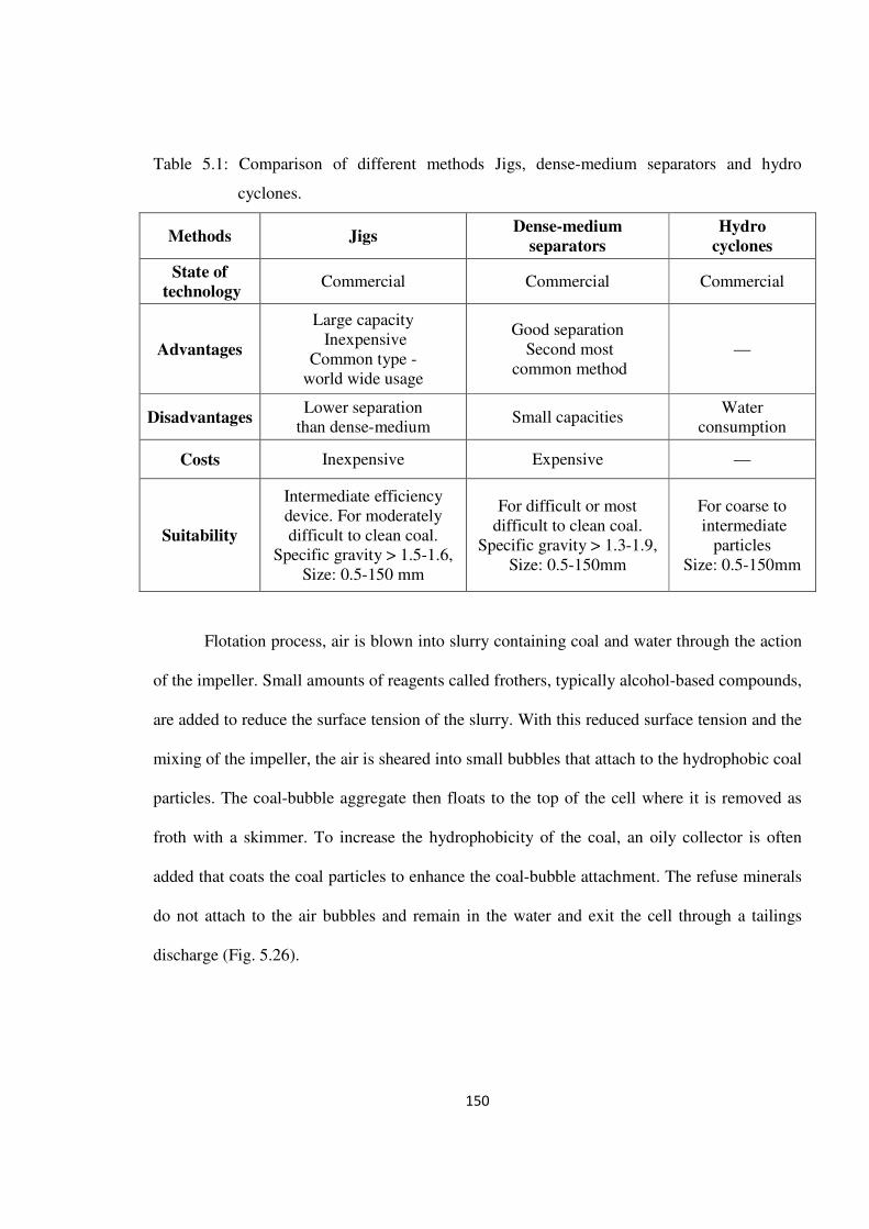
Table 5.1: Comparison of different methods Jigs, dense-medium separators and hydro
cyclones.
Methods Jigs Dense-medium
separators
Hydro
cyclones
State of
technology Commercial Commercial Commercial
Advantages
Large capacity Inexpensive
Common type - world wide usage
Good separation Second most
common method —
Disadvantages Lower separation
than dense-medium Small capacities
Water consumption
Costs Inexpensive Expensive —
Suitability
Intermediate efficiency device. For moderately difficult to clean coal.
Specific gravity > 1.5-1.6, Size: 0.5-150 mm
For difficult or most difficult to clean coal.
Specific gravity > 1.3-1.9, Size: 0.5-150mm
For coarse to intermediate
particles Size: 0.5-150mm
Flotation process, air is blown into slurry containing coal and water through the action
of the impeller. Small amounts of reagents called frothers, typically alcohol-based compounds,
are added to reduce the surface tension of the slurry. With this reduced surface tension and the
mixing of the impeller, the air is sheared into small bubbles that attach to the hydrophobic coal
particles. The coal-bubble aggregate then floats to the top of the cell where it is removed as
froth with a skimmer. To increase the hydrophobicity of the coal, an oily collector is often
added that coats the coal particles to enhance the coal-bubble attachment. The refuse minerals
do not attach to the air bubbles and remain in the water and exit the cell through a tailings
discharge (Fig. 5.26).

151
Fig. 5.26: processing of Froth flotation cell.
Flotation processing utilize collector as a hydrophobe material and for stability of
bubbles of the frother. Oxidation is a natural process that can continuously decrease the
hydrophobicity of coal. In the flotation pulp, not only the added chemicals but also the
dissolved mineral species, released from coal itself during grinding and pulping, can play an
important role in governing flotation. Water of the final concentrate got from flotation process
is removed by filters.
When fine coal is subjected to the flotation process, greater amounts of promoter and
frother agent are adsorbed due to high surface area (Fig. 5.27). In fact, the liberated fine
mineral matter itself attaches to the hydrophobic coal particles, resulting in a slime coating
with an attendant pseudo-depression phenomenon. As a result of these complications, the
production of super clean coal by conventional froth flotation has been found to be a most
difficult task.

152
Although some success has been achieved utilizing sodium hypochlorite for removal
of sulphatic and organic sulfur, such oxidation practice has been generally unsuccessful in the
removal of pyritic sulfur. These problems are most significant for coals such as bituminous
(which contain medium and high volatile materials) and sub-bituminous coals. In most
operating coal-cleaning plants, a significant amount of pyrite is recovered through the froth
during flotation of high-sulfur coal. pyrite recovery is commonly believed to be a result of
pyrite particles floating due to hydrophobicity. However, even though a wide range of pyrite
depressants have been reported over the years, there is no use of these depressants for
industrial coal flotation, which suggests that pyrite can become naturally hydrophobic at
neutral pH under certain conditions (Kawatra and Eisele, 1997).
5.4.2.9.1 Collector
Collector is used in flotation process as a hydrophobe material. In coal flotation, white
oil and disel oil are used as a collector and co-collector. Bituminous coals with high
bituminization rank are floatable in frother whereas flotation of bituminous coals with medium
bituminization rank needs non ionic oils (oil fuels) with 0.5-1.5 kg/ton value. Collector value
for floating anthracite is about 1.5 kg/ton. For floating coals of bituminization rank huge
amounts of collector are needed. This suggests that the effect of both the frother and collector
on water transfer rates is first of all determined by the transfer of solids to the froth, and thus
by the effect of these two agents on the solids transfer to froth (Boylu and Laskowski, 2007).
5.4.2.9.2 Froth flotation
Froth flotation, separation of fine coal particles selectively from associated minerals in
water slurries, is achieved by attachment to rising air bubbles. Frothers are utilized in flotation
process to enhance generation of fine bubbles and to stabilize the froth. Main role of the

153
frothers are maintenance of a large amounts of bubbles of suitable size. Produced bubbles
should have sufficient resistance that enables to transfer coal grains of pulp area to froth area.
But frothers should not be too resistant that can produce problems in filters.
In Zarand coal washing plant pine oil (peen evil) is used as a frother in floatation
system. Pine oil is a convoluted alcohol derived from wood. Pine oil is an essential oil
obtained by the steam distillation of needles, twigs and cones from a variety of pine species.
Polyglycol ether and alcohol frothers present good correlation between fundamental two phase
frother characterization indices and coal flotation performance (Gupta et.al., 2007).
5.4.3 Drier building
Concentrates from jig, dynawhirlpool, spiral and flotation circuits need to be dried for
reaching desirable moisture. Coal supplied to the Eisfahan iron melting plant should not
contain more than 10% moisture, hence it is necessary to provide place for drying coal.
In the drier building, heat of the drier section is provided by five ovens. Since, electricity
expenses on drier unit are high, coal is dried on platform constructed in the vicinity of main
building with the aid of air and sunshine (Fig. 5.28). In this plant only 10% of production is
dried in drier building and the remaining production (90%) is dried by atmospheric heat.
5.4.4 Storage building and loading concentrate
In this unit, four tanks have been constructed to store the processed fine coal. Capacity
of each one is about 1200 ton. These tanks are equiped with a mobile conveyor belt. These
conveyor belts are used for loading concentrate to wagons. The wagons are transported to
Eisfahan iron melting plant.
Coal with 10% moisture and maximum 13% ash-content are loaded in 51 ton wagons
and carried through the Zarand railway to Eisfahan. These coals are utilized to provide coke to
154
the blast furnace of Eisfahan Iron melting. Coal washing plant has ability of washing about 2
million ton of coal. Right now, it is washing 3000 to 4000 ton of coal per day and produces
1500 to 2000 ton of coal concentrate. Production value of concentrate depends on the coal
value of Run of Mine (ROM).
5.5 BENEFITS OF USING WASHED COAL
- Increased generation efficiency, mainly due to the reduction in energy loss as inert
material does not pass through the combustion process.
- Increased plant availability
- Reduced investment costs
- Reduced operation and maintenance (O&M) costs due to less wear and reduced costs
for fuel and ash handling
- Energy conservation in the transportation sector and lower transportation costs
- Less impurities and improved coal quality
- Reduced load on the air pollution control system
- Reduction in the amount of solid waste that has to be disposed off

155
Fig. 5.2: The entrance of a tunnel with 4 m height. Fig. 5.3: Surface and underground plan of coal mining process.
Fig. 5.5: Jackhammer (a) and handing perforator (b). Fig. 5.6: Telescope tripod that is separated from perforator.

156
Fig. 5.7: Temp as cutting coal machine. Fig. 5.8: Raise boring machine for drilling raises less than 8m.
Fig. 5.9: Jumbo drilling machine for drilling resistance rocks. Fig. 5.10: Hydraulic jacks for supporting tunnel walls.
157
Fig. 5.11: LHD loader for loading materials in face wall. Fig. 5.12: Wood cutting machine.
Fig. 5.13: Battery to charge locomotive. Fig. 5.14: Coal bunkers with conveyer belt.

158
Fig. 5.15: Photograph showing coal washery units.
Fig. 5.16: Feeding unit of the coal washery.
Storage building and
loading building
Main and drier
buildings Feeding unite
159
Fig. 5.17: Storage yard of the coal around feeding unit. Fig. 5.20: Heavy media separator unit (1.7 g/cm3 density).
Fig. 5.21: Jig unit which containing of three baths. Fig. 5.22: Bucket elevator which replace jig production.

160
Fig. 5.23: Dynawhirlpool separators. Fig. 5.24: Spiral separators and hydrocyclones.
Fig. 5.27: Photograph showing part of flotation unit. Fig. 5.28: Drier platform in vicinity concentrate plan.