contents522955189.online.de/resources/emc.pdffeatures characteristics - dataline noise filter is...
TRANSCRIPT
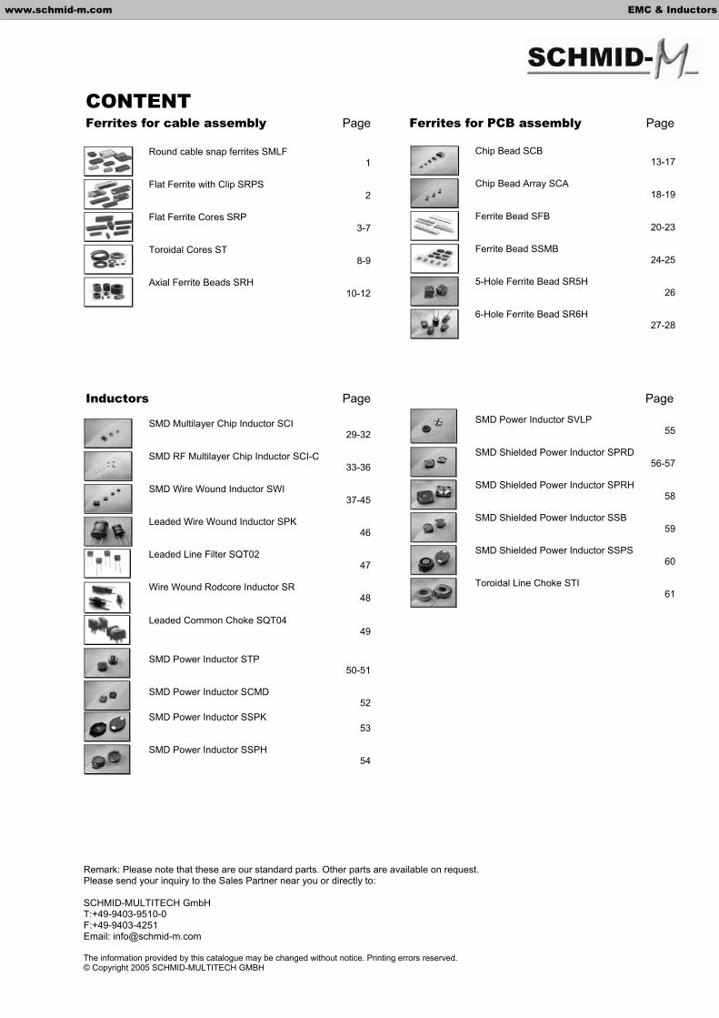
CONTENTFerrites for cable assembly Page Ferrites for PCB assembly Page
Inductors Page Page
Round cable snap ferrites SMLF 1
Flat Ferrite with Clip SRPS 2
Flat Ferrite Cores SRP 3-7
Toroidal Cores ST 8-9
Axial Ferrite Beads SRH 10-12
Chip Bead SCB 13-17
Chip Bead Array SCA 18-19
Ferrite Bead SFB 20-23
Ferrite Bead SSMB 24-25
5-Hole Ferrite Bead SR5H 26
6-Hole Ferrite Bead SR6H 27-28
SMD Multilayer Chip Inductor SCI 29-32
SMD RF Multilayer Chip Inductor SCI-C 33-36
SMD Wire Wound Inductor SWI 37-45
Leaded Wire Wound Inductor SPK 46
Leaded Line Filter SQT02 47
Wire Wound Rodcore Inductor SR 48
Leaded Common Choke SQT04 49
SMD Power Inductor SCMD 52
SMD Power Inductor STP 50-51
SMD Power Inductor SSPK 53
SMD Power Inductor SSPH 54
SMD Power Inductor SVLP 55
SMD Shielded Power Inductor SPRD 56-57
SMD Shielded Power Inductor SPRH 58
SMD Shielded Power Inductor SSB 59
SMD Shielded Power Inductor SSPS 60
Toroidal Line Choke STI 61
Remark: Please note that these are our standard parts. Other parts are available on request. Please send your inquiry to the Sales Partner near you or directly to:
SCHMID-MULTITECH GmbH T:+49-9403-9510-0 F:+49-9403-4251 Email: [email protected]
The information provided by this catalogue may be changed without notice. Printing errors reserved. © Copyright 2005 SCHMID-MULTITECH GMBH
www.schmid-m.com EMC & Inductors

Features Characteristics
- Dataline Noise Filter is hinged clamp and also has EMI performance - Internal dimensions from 1.9mm to 35mm radius - Precision formed smooth surface prevent damage to wire insulation - Customer designs available
Ordering Information
SMLF 65
Shapes
SMLF-35 SMLF-50 SMLF-65 SMLF-75 SMLF-80
SMLF-90 SMLF-100 SMLF-120 SMLF-130 SMLF-150
DimensionsSeries
www.schmid-m.com 1 EMC & Inductors
Round cable snap ferrite –SMLF Series
Impedance ( )Part No.
25MHz 100MHz
SMLF-35 80 200
SMLF-50 85 150
SMLF-65 125 275
SMLF-75 130 240
SMLF-80 110 180
SMLF-90 150 270
SMLF-100 150 270
SMLF-120 50 100
SMLF-130 140 300
SMLF-150 30 125

Ordering Information
SRPS 63.5x6.35x28.5 N1
Clip MaterialN1, N2, N3: Nylon-66 (UL) Flame Class: 94V-2
Characteristics
Impedance ( )min
Part No. Fig. A B C D E Curve
25MHz 100MHz
SRPS38.0x6.35x15.0M2 5 38.0 ± 1.0 12.7 ± 0.5 26.6 ± 0.7 15.0 ± 0.4 1.6 ± 0.4 A 40 115 SRPS38.0x6.35x25.4M1 4 38.0 ± 1.0 12.7 ± 0.5 26.6 ± 0.7 25.4 ± 0.7 1.6 ± 0.4 B 75 140 SRPS45.0x6.35x15.0M2 5 45.0 ± 1.0 12.7 ± 0.5 34.4 ± 0.7 15.0 ± 0.4 1.6 ± 0.4 C 40 90 SRPS45.0x6.35x28.5M1 4 45.0 ± 1.0 12.7 ± 0.5 34.4 ± 0.7 28.5 ± 0.7 1.6 ± 0.4 D 70 140 SRPS45.0x6.35x28.5N3 3 45.0 ± 1.0 12.7 ± 0.5 34.4 ± 0.7 28.5 ± 0.7 1.6 ± 0.4 D 70 140 SRPS55.1x6.35x15.0M2 5 55.1 ± 1.0 12.7 ± 0.5 43.7 ± 1.0 15.0 ± 0.4 1.6 ± 0.4 E 40 105 SRPS55..1x6.35x28.5M1 4 55.1 ± 1.0 12.7 ± 0.5 43.7 ± 1.0 28.5 ± 0.7 1.6 ± 0.4 F 65 140 SRPS55.1x6.35x28.5N3 3 55.1 ± 1.0 12.7 ± 0.5 43.7 ± 1.0 28.5 ± 0.7 1.6 ± 0.4 F 65 140 SRPS63.5x6.35x15.0M2 5 63.5 ± 1.2 12.7 ± 0.5 52.0 ± 1.0 15.0 ± 0.4 1.6 ± 0.4 G 40 95SRPS63.5x6.35x28.5M1 4 63.5 ± 1.2 12.7 ± 0.5 52.0 ± 1.0 28.5 ± 0.7 1.6 ± 0.4 H 60 150 SRPS63.5x6.35x28.5N1 1 63.5 ± 1.2 12.7 ± 0.5 52.0 ± 1.0 28.5 ± 0.7 1.6 ± 0.4 H 60 150 SRPS63.5x6.35x28.5N2 2 63.5 ± 1.2 12.7 ± 0.5 52.0 ± 1.0 28.5 ± 0.7 1.6 ± 0.4 H 60 150 SRPS63.5x6.35x28.5N3 3 63.5 ± 1.2 12.7 ± 0.5 52.0 ± 1.0 28.5 ± 0.7 1.6 ± 0.4 H 60 150 SRPS76.2x6.35x28.5M1 1 76.2 ± 1.5 12.7 ± 0.5 65.2 ± 1.2 28.5 ± 0.7 1.6 ± 0.4 I 60 190 SRPS76.2x6.35x28.5N3 3 76.2 ± 1.5 12.7 ± 0.5 65.2 ± 1.2 28.5 ± 0.7 1.6 ± 0.4 I 60 190
Clip
Dimensions
Series
www.schmid-m.com 2 EMC & Inductors
Flat Ferrite with Clip – SRPS Series
Features
- Precision formed smooth surfaces prevent damage to wire insulation. - Applications: Cables between pc boards and data connectors, floppy disk and hard cables with series digital signal busses.
Shapes1 2
3 4
5

Ordering Information
SRP 31.0x5.0x12.0
Characteristics
Impedance ( )min
Part No. Fig. A B C D E
25MHz 100MHz
SRP16.0x5.0x11.5 1 16.0 ± 0.4 5.0 ± 0.3 11.5 ± 0.4 12.0 ± 0.5 0.5 +0.6 -0.1 44 90SRP16.0x5.0x11.5 2 16.0 ± 0.4 5.0 ± 0.3 11.5 ± 0.4 15.0 ± 0.6 0.5 +0.6 -0.1 50 110 SRP18.0x5.0x8.0 3 18.0 ± 0.4 5.0 ± 0.3 14.0 ± 0.4 8.0 ± 0.4 1.0 ± 0.3 24 55
SRP20.5x3.5x15.0 4 20.5 ± 0.5 3.5 +0.15 -0.25 16.5 ± 0.4 15.0 ± 0.6 0.5 +0.2 -0.15 34 88 SRP22.35x7.75x19.05 5 22.35 ± 0.51 7.75 ± 0.38 14.0 ± 0.25 19.05 ± 0.64 1.5 ± 0.25 68 120
SRP23.3x3.0x7.0 6 23.3 ± 0.7 3.0 ± 0.3 20.0 ± 0.5 7.0 ± 0.4 0.9 ± 0.15 20 60 SRP23.5x6.3x10.0 7 23.5 ± 0.7 6.3 ± 0.5 18.4 ± 0.4 10.0 ± 0.4 1.1 ± 0.3 32 75 SRP25.0x5.0x12.0 8 25.0 ± 0.7 5.0 ± 0.4 21.0 ± 0.5 12.0 ± 0.5 1.1 ± 0.2 27 75 SRP25.0x3.5x15.0 9 25.0 ± 0.8 3.5 +0.15 -0.25 24.0 ± 0.4 15.0 ± 0.6 0.5 +0.2 -0.15 30 88SRP28.0x6.5x15.0 10 28.0 ± 0.8 6.5 ± 0.5 23.0 ± 0.5 15.0 ± 0.6 1.0 ± 0.3 30 85 SRP28.5x6.5x18.0 11 28.5 ± 0.8 6.5 ± 0.5 23.5 ± 0.5 18.0 ± 0.7 1.0 ± 0.3 40 95 SRP28.0x7.7x14.6 12 28.0 ± 0.8 7.7 ± 0.5 23.0 ± 0.5 14.6 ± 0.4 1.4 ± 0.4 38 85 SRP28.0x7.7x22.0 13 28.0 ± 0.8 7.7 ± 0.5 23.0 ± 0.5 22.0 ± 0.6 1.4 ± 0.4 52 110 SRP28.6x7.7x25.0 28.6 ± 0.85 7.7 ± 0.5 23.6 ± 0.8 25.0 ± 0.8 1.8 ±0.4 45 95 SRP31.0x5.0x8.0 14 31.0 ± 0.8 5.0 ± 0.4 27.0 ± 0.6 8.0 ± 0.4 0.5 +0.7 -0.1 21 60 SRP31.0x5.0x9.0 15 31.0 ± 0.8 5.0 ± 0.4 27.0 ± 0.6 9.0 ± 0.4 0.5 +0.7 -0.1 25 75
SRP31.0x5.0x12.0 16 31.0 ± 0.8 5.0 ± 0.4 27.0 ± 0.6 12.0 ± 0.5 0.5 +0.7 -0.1 30 85 SRP31.0x5.0x22.0 17 31.0 ± 0.8 5.0 ± 0.4 27.0 ± 0.6 22.0 ± 0.6 0.5 +0.7 -0.1 46 130 SRP33.5x3.5x15.0 18 33.5 ± 0.9 3.5 ± 0.3 27.0 ± 0.6 15.0 ± 0.6 1.4 ± 0.4 21 68 SRP33.5x4.0x12.0 19 33.5 ± 0.9 4.0 +0 -0.2 27.0 ± 0.6 12.0 ± 0.5 1.4 ± 0.4 19 60 SRP33.5x6.5x7.0 20 33.5 ± 0.9 6.5 ± 0.5 27.0 ± 0.6 7.0 ± 0.4 1.4 ± 0.4 20 57 SRP33.5x6.5x8.0 21 33.5 ± 0.9 6.5 ± 0.5 27.0 ± 0.6 8.0 ± 0.4 1.4 ± 0.4 21 60
SRP33.5x6.5x10.0 22 33.5 ± 0.9 6.5 ± 0.5 27.0 ± 0.6 10.0 ± 0.4 1.4 ± 0.4 24 65 SRP33.5x6.5x15.0 23 33.5 ± 0.9 6.5 ± 0.5 27.0 ± 0.6 15.0 ± 0.6 1.4 ± 0.4 32 81 SRP33.5x6.5x22.0 24 33.5 ± 0.9 6.5 ± 0.5 27.0 ± 0.6 22.0 ± 0.6 1.4 ± 0.4 43 95
SRP38.1x12.0x25.4 25 38.1 ± 1.0 12.0 ± 0.6 26.7 ± 0.6 25.4 ± 0.8 1.9 ± 0.4 83 145 SRP40.0x6.5x6.0 26 40.0 ± 1.0 6.5 ± 0.5 35.0 ± 0.7 6.0 ± 0.3 1.4 ± 0.4 16 50
SRP40.0x6.5x12.0 27 40.0 ± 1.0 6.5 ± 0.5 35.0 ± 0.7 12.0 ± 0.5 1.4 ± 0.4 25 72 SRP40.0x6.5x18.0 28 40.0 ± 1.0 6.5 ± 0.5 35.0 ± 0.7 18.0 ± 0.5 1.4 ± 0.4 32 84 SRP40.0x6.5x20.0 29 40.0 ± 1.0 6.5 ± 0.5 35.0 ± 0.7 20.0 ± 0.6 1.4 ± 0.4 35 88 SRP40.0x6.5x22.0 30 40.0 ± 1.0 6.5 ± 0.5 35.0 ± 0.7 22.0 ± 0.6 1.4 ± 0.4 37 95
SRP45.1x12.5x10.0 31 45.1 ± 1.0 12.5 ± 0.6 34.5 ± 0.8 10.0 ± 0.4 1.5 ± 0.5 30 72 SRP45.1x12.5x28.6 32 45.1 ± 1.0 12.5 ± 0.6 34.5 ± 0.8 28.6 ± 0.8 1.5 ± 0.5 80 165 SRP45.2x6.5x12.0 45.2 ± 1.0 6.5 ± 0.5 40.0 ± 0.8 12.0 ± 0.5 1.4 ± 0.4 24 72 SRP49.6x4.0x12.0 49.6 ± 1.0 4.0 ± 0.2 44.0 ± 0.8 12.0 ± 0.5 1.4 ± 0.4 19 63 SRP49.6x6.5x12.0 49.6 ± 1.0 6.5 ± 0.5 44.0 ± 0.8 12.0 ± 0.5 1.4 ± 0.4 22 68 SRP57.6x6.5x12.0 57.6 ± 1.2 6.5 ± 0.5 52.0 ± 1.0 12.0 ± 0.5 1.4 ± 0.4 22 70 SRP60.6x6.5x12.0 60.6 ± 1.2 6.5 ± 0.5 55.0 ± 1.0 12.0 ± 0.5 1.4 ± 0.4 28 92
Dimensions
Series
www.schmid-m.com 3 EMC & Inductors
Flat Ferrite Cores – SRP Series
Features
- Slot lengths from 16mm to 60mm. Precision formed smooth surfaces prevent damage to wire insulation - Applications: Internal floppy disk and harddisk ribbon cables. Internal ribbon cables between circuit boards and data connectors. Internal ribbon cables with series digital signal busses
Shapes
Shape#3: SRP2877146 Shape#2: SRP22357751905 / SRP23337 / SRP2356310 / SRP287722 / SRP38112254 / SRP45112510 / SRP451125286 Shape#1: all other parts
1 2
3

1 2
3 4
5 6
7 8
www.schmid-m.com 4 EMC & Inductors

www.schmid-m.com 5 EMC & Inductors
9 10
11 12
13 14
15 16
www.schmid-m.com 6 EMC & Inductors
17 18
19 20
21 22
23 24

www.schmid-m.com 7 EMC & Inductors
25 26
27 28
29 30
31 32
Features
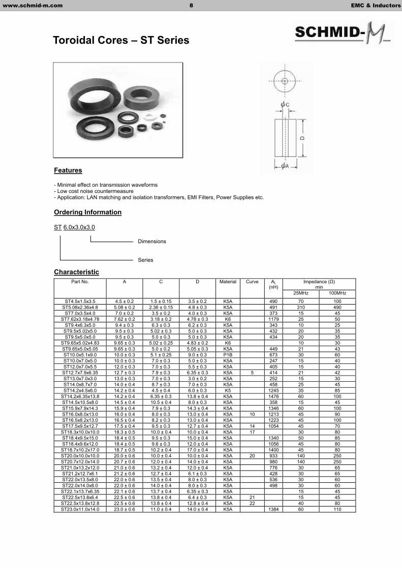
- Minimal effect on transmission waveforms - Low cost noise countermeasure - Application: LAN matching and isolation transformers, EMI Filters, Power Supplies etc.
Ordering Information
ST 6.0x3.0x3.0
CharacteristicImpedance ( )
minPart No. A C D Material Curve AL
(nH)25MHz 100MHz
ST4.5x1.5x3.5 4.5 ± 0.2 1.5 ± 0.15 3.5 ± 0.2 K5A 490 70 100 ST5.08x2.36x4.8 5.08 ± 0.2 2.36 ± 0.15 4.8 ± 0.3 K5A 491 310 490 ST7.0x3.5x4.0 7.0 ± 0.2 3.5 ± 0.2 4.0 ± 0.3 K5A 373 15 45
ST7.62x3.18x4.78 7.62 ± 0.2 3.18 ± 0.2 4.78 ± 0.3 K6 1179 25 50 ST9.4x6.3x5.0 9.4 ± 0.3 6.3 ± 0.3 6.2 ± 0.3 K5A 343 10 25
ST9.5x5.02x5.0 9.5 ± 0.3 5.02 ± 0.3 5.0 ± 0.3 K5A 432 20 35 ST9.5x5.0x5.0 9.5 ± 0.3 5.0 ± 0.3 5.0 ± 0.3 K5A 434 20 35
ST9.65x5.02x4.83 9.65 ± 0.3 5.02 ± 0.25 4.83 ± 0.2 K6 10 30 ST9.65x5.0x5.05 9.65 ± 0.3 5.0 ± 0.2 5.05 ± 0.3 K5A 449 21 43 ST10.0x5.1x9.0 10.0 ± 0.3 5.1 ± 0.25 9.0 ± 0.3 P1B 673 30 60 ST10.0x7.0x5.0 10.0 ± 0.3 7.0 ± 0.3 5.0 ± 0.3 K5A 247 15 40 ST12.0x7.0x5.5 12.0 ± 0.3 7.0 ± 0.3 5.5 ± 0.3 K5A 405 15 40 ST12.7x7.9x6.35 12.7 ± 0.3 7.9 ± 0.3 6.35 ± 0.3 K5A 5 414 21 42 ST13.0x7.0x3.0 13.0 ± 0.3 7.0 ± 0.3 3.0 ± 0.2 K5A 252 15 30 ST14.0x8.7x7.0 14.0 ± 0.4 8.7 ± 0.3 7.0 ± 0.3 K5A 458 25 45 ST14.2x4.5x6.0 14.2 ± 0.4 4.5 ± 0.4 6.0 ± 0.3 K5 1245 35 85
ST14.2x6.35x13.8 14.2 ± 0.4 6.35 ± 0.3 13.8 ± 0.4 K5A 1476 60 100 ST14.5x10.5x8.0 14.5 ± 0.4 10.5 ± 0.4 8.0 ± 0.3 K5A 358 15 45 ST15.9x7.9x14.3 15.9 ± 0.4 7.9 ± 0.3 14.3 ± 0.4 K5A 1346 60 100 ST16.0x8.0x13.0 16.0 ± 0.4 8.0 ± 0.3 13.0 ± 0.4 K5A 10 1213 45 90 ST16.5x8.2x13.0 16.5 ± 0.4 8.2 ± 0.3 13.0 ± 0.4 K5A 1223 45 100 ST17.5x9.5x12.7 17.5 ± 0.4 9.5 ± 0.3 12.7 ± 0.4 K5A 14 1054 45 70
ST18.3x10.0x10.0 18.3 ± 0.5 10.0 ± 0.4 10.0 ± 0.4 K5A 17 30 80 ST18.4x9.5x15.0 18.4 ± 0.5 9.5 ± 0.3 15.0 ± 0.4 K5A 1340 50 85 ST18.4x9.6x12.0 18.4 ± 0.5 9.6 ± 0.3 12.0 ± 0.4 K5A 1056 45 80
ST18.7x10.2x17.0 18.7 ± 0.5 10.2 ± 0.4 17.0 ± 0.4 K5A 1400 45 80 ST20.0x10.0x10.0 20.0 ± 0.6 10.0 ± 0.4 10.0 ± 0.4 K5A 20 933 140 250 ST20.7x12.0x14.0 20.7 ± 0.6 12.0 ± 0.4 14.0 ± 0.4 K5A 980 140 250 ST21.0x13.2x12.0 21.0 ± 0.6 13.2 ± 0.4 12.0 ± 0.4 K5A 776 30 65 ST21.2x12.7x6.1 21.2 ± 0.6 12.7 ± 0.4 6.1 ± 0.3 K5A 428 30 65 ST22.0x13.5x8.0 22.0 ± 0.6 13.5 ± 0.4 8.0 ± 0.3 K5A 536 30 60 ST22.0x14.0x8.0 22.0 ± 0.6 14.0 ± 0.4 8.0 ± 0.3 K5A 498 30 60
ST22.1x13.7x6.35 22.1 ± 0.6 13.7 ± 0.4 6.35 ± 0.3 K5A 15 45 ST22.5x13.8x6.4 22.5 ± 0.6 13.8 ± 0.4 6.4 ± 0.3 K5A 21 15 45
ST22.5x13.8x12.8 22.5 ± 0.6 13.8 ± 0.4 12.8 ± 0.4 K5A 22 40 80 ST23.0x11.0x14.0 23.0 ± 0.6 11.0 ± 0.4 14.0 ± 0.4 K5A 1384 60 110
Dimensions
Series
www.schmid-m.com 8 EMC & Inductors
Toroidal Cores – ST Series

Impedance ( )min
Part No. A C D Material Curve AL(nH)
25MHz 100MHz
ST23.0x13.5x6.34 23.0 ± 0.6 13.5 ± 0.4 6.34 ± 0.4 K5A 463 15 45 ST23.5x12.6x9.4 23.5 ± 0.6 12.6 ± 0.4 9.4 ± 0.3 K6A 1703 60 120
ST24.0x11.0x14.0 24.0 ± 0.6 11.0 ± 0.4 14.0 ± 0.4 K5A 1456 60 100 ST24.0x14.0x11.0 24.0 ± 0.6 14.0 ± 0.4 11.0 ± 0.4 K5A 35 63 ST25.0x15.0x12.0 25.0 ± 0.6 15.0 ± 0.5 12.0 ± 0.4 K5A 467 35 80 ST28.0x16.0x13.0 28.0 ± 0.6 16.0 ± 0.3 13.0 ± 0.4 K6 26 993 40 80 ST29.0x19.0x7.5 29.0 ± 0.6 19.0 ± 0.5 7.5 ± 0.3 K5A 438 20 50 ST31.0x19.0x8.0 31.0 ± 0.9 19.0 ± 0.5 8.0 ± 0.3 K5 27 25 60
ST31.75x19.05x16.0 31.75 ± 0.8 19.05 ± 0.5 16.0 ± 0.4 K5A 28 50 90 ST31.75x19.05x22.5 31.75 ± 0.8 19.05 ± 0.8 22.5 ± 0.6 K5A 60 90 ST35.6x23.0x12.7 35.6 ± 0.8 23.0 ± 0.6 12.7 ± 0.4 K5A 29 765 25 90 ST35.6x5.4x7.5 35.6 ± 0.8 25.4 ± 0.6 7.5 ± 0.2 K5A 30 351 25 90
ST40.6x27.5x15.0 40.6 ± 1.0 27.5 ± 0.6 15.0 ± 0.4 K5A 808 35 85 ST40.6x27.0x15.0 40.6 ± 1.0 27.0 ± 0.6 15.0 ± 0.4 K5A 845 35 85
5 10 14
17 20 21
22 26 27
28 29 30
www.schmid-m.com 9 EMC & Inductors

Features
- Employ High-Performance ferrites with superior frequency characteristic. Compact and high performance. Easy installation. - Countermeasure against radiated emissions – full compliance with FCC
Ordering Information
SRH 11.0x5.0x25.0
Characteristic
Impedance ( )min
Part No. A C D Material Curve
25MHz 100MHz SRH2.5x0.8x3.0 2.5 ± 0.15 0.8 ± 0.15 3.0 ± 0.2 K5A 20 30 SRH2.5x1.0x3.0 2.5 ± 0.15 1.0 ± 0.15 3.0 ± 0.2 K5A 10 30 SRH3.5x0.9x6.0 3.5 ± 0.15 0.9 ±0.1 6.0 ± 0.3 K5A 50 75 SRH3.5x1.3x3.0 3.5 ± 0.15 1.3 ±0.1 3.0 ±0.2 K5A 10 20 SRH3.5x1.0x5.0 3.5 ± 0.15 1.0 ± 0.15 5.0 ± 0.3 K5A 20 45
SRH4.0x2.0x15.0 4.0 ± 0.2 2.0 ± 0.15 15.0 ± 0.5 K5 50 80 SRH4.0x2.0x25.0 4.0 ± 0.2 2.0 ± 0.15 25.0 ± 0.3 K5A 90 120 SRH4.0x2.2x6.0 4.0 ± 0.2 2.2 ± 0.15 6.0 ± 0.3 K5A 20 40
SRH4.0x2.2x25.0 4.0 ± 0.2 2.2 ± 0.15 25.0 ± 0.6 K5A 90 120 SRH4.1x2.0x6.0 4.1 ± 0.2 2.0 ± 0.15 6.0 ± 0.3 K5A 20 30
SRH4.2x2.0x15.0(R) 4.2 ± 0.2 2.0 ± 0.15 15.0 ± 0.4 C3B 45 90 SRH4.2x2.0x15.0(C) 4.2 ± 0.2 2.0 ± 0.15 15.0 ± 0.4 C3B 45 90
SRH4.5x1.5x7.0 4.5 ± 0.2 1.5 ± 0.1 7.0 ± 0.3 K5 40 80 SRH4.5x2.5x7.0 4.5 ± 0.2 2.5 ± 0.15 7.0 ± 0.3 K5A 35 65
SRH4.9x2.0x36.0 4.9 ± 0.2 2.0 ± 0.15 36.0 ± 0.8 K6 140 200 SRH5.08x2.29x10 5.08 ± 0.2 2.29 ± 0.15 10.0 ± 0.4 K5A 40 65
SRH6.35x2.95x25.4 6.35 ± 0.2 2.95 ± 0.15 25.4 ± 0.6 K5A 108 200 SRH6.35x3.2x12.7 6.35 ± 0.2 3.2 ± 0.2 12.7 ± 0.4 K5A 55 102 SRH6.5x4.0x10.0 6.5 ± 0.2 4.0 ± 0.2 10.0 ± 0.4 K5A 20 40 SRH6.5x4.5x10.0 6.5 ± 0.2 4.5 ± 0.2 10.0 ± 0.4 K5A 15 35
SRH7.52x2.39x7.54 7.52 ± 0.2 2.39 ± 0.15 7.54 ± 0.3 K5A 30 60 SRH7.8x4.0x13.0 7.8 ± 0.2 4.0 ± 0.2 13.0 ± 0.4 K5A 45 80 SRH7.8x5.0x12.5 7.8 ± 0.2 5.0 ± 0.25 12.5 ± 0.4 K5A 30 60 SRH8.0x5.3x15.0 8.0 ± 0.2 5.3 ± 0.25 15.0 ± 0.4 K5A 40 80 SRH9.0x5.0x16.0 9.0 ± 0.3 5.0 ± 0.25 16.0 ± 0.4 K5A 50 80
SRH9.05x4.7x16.2 9.05 ± 0.3 4.7 ± 0.2 16.2 ± 0.4 K5A 60 110 SRH9.5x4.8x14.5 9.5 ± 0.3 4.8 ± 0.2 14.5 ± 0.4 K5A 53 75 SRH9.5x5.0x14.5 9.5 ± 0.3 5.0 ± 0.25 14.5 ± 0.4 K5A 50 100 SRH9.5x5.2x9.5 9.5 ± 0.3 5.2 ± 0.25 9.5 ± 0.4 K5A 35 65
SRH9.65x5.02x10.4 9.65 ± 0.3 5.02 ± 0.25 10.4 ± 0.4 K5A 30 60 SRH9.7x3.8x10.2 9.7 ± 0.3 3.8 ± 0.2 10.2 ± 0.4 K5A 60 100 SRH9.8x6.3x15.7 9.8 ± 0.3 6.3 ± 0.3 15.7 ± 0.4 K5A 45 65
SRH10.0x5.0x25.0 10.0 ± 0.3 5.0 ± 0.25 25.0 ± 0.6 K5A 125 160
Dimensions
Series
www.schmid-m.com 10 EMC & Inductors
Axial Ferrite Bead – SRH Series

Impedance ( )min
Part No. A C D Material Curve
25MHz 100MHz SRH10.0x5.5x2.5 10.0 ± 0.3 5.5 ± 0.25 2.5 ± 0.6 K5A 90 160
SRH10.0x6.0x14.0 10.0 ± 0.3 6.0 ± 0.3 14.0 ± 0.4 K5A 35 75 SRH10.0x6.15x6.2 10.0 ± 0.3 6.15 ± 0.3 6.2 ± 0.3 K5A 45 85 SRH10.0x7.0x10.0 10.0 ± 0.3 7.0 ± 0.3 10.0 ± 0.4 K5A 20 40 SRH10.5x5.5x20.0 10.5 ± 0.3 5.5 ± 0.25 20.0 ± 0.5 K5A 65 120 SRH11.0x5.0x25.0 11.0 ± 0.3 5.0 ± 0.25 25.0 ± 0.6 K5A 115 180
SRH11.3x5.95x12.0 11.3 ± 0.3 5.95 ± 0.25 12.0 ± 0.4 K5A 40 70 SRH11.86x7.4x15.0 11.86 ± 0.3 7.4 ± 0.3 15.0 ± 0.4 K5A 35 75 SRH12.0x4.0x23.0 12.0 ± 0.3 4.0 ± 0.2 23.0 ± 0.5 K5A 4 160 230 SRH12.0x5.6x20.0 12.0 ± 0.3 5.6 ± 0.25 20.0 ± 0.5 K5A 3 100 200 SRH12.0x8.0x13.0 12.0 ± 0.3 8.0 ± 0.3 13.0 ± 0.4 K5A 35 75 SRH12.0x8.5x15.0 12.0 ± 0.3 8.5 ± 0.3 15.0 ± 0.4 K5A 30 50 SRH12.3x5.0x12.7 12.3 ± 0.3 5.0 ± 0.25 12.7 ± 0.4 K5A 60 120 SRH12.7x6.0x21.7 12.7 ± 0.3 6.0 ± 0.3 21.7 ± 0.5 K6 85 135 SRH12.7x7.9x12.7 12.7 ± 0.3 7.9 ± 0.3 12.7 ± 0.4 K5A 30 60 SRH13.0x7.0x15.0 13.0 ± 0.3 7.0 ± 0.3 15.0 ± 0.4 P3 75 140 SRH14.0x6.8x15.0 14.0 ± 0.4 6.8 ± 0.3 15.0 ± 0.4 K5 65 120 SRH14.0x7.8x15.0 14.0 ± 0.4 7.8 ± 0.3 15.0 ± 0.4 K5A 35 70 SRH14.2x4.5x28.5 14.2 ± 0.4 4.5 ± 0.2 28.5 ± 0.6 K5A 160 300
SRH14.2x6.35x28.5 14.2 ± 0.4 6.35 ± 0.3 28.5 ± 0.6 K5A 7 100 190 SRH14.2x6.35x36.0 14.2 ± 0.4 6.35 ± 0.3 36.0 ± 0.8 K5A 150 280 SRH14.2x7.2x28.5 14.2 ± 0.4 7.2 ± 0.3 28.5 ± 0.6 K5A 130 210 SRH14.2x7.0x28.5 14.2 ± 0.4 7.0 ± 0.3 28.5 ± 0.6 K5A 8 100 120 SRH14.2x8.0x23.5 14.2 ± 0.4 8.0 ± 0.3 23.5 ± 0.5 K5A 65 135 SRH14.2x8.0x28.5 14.2 ± 0.4 8.0 ± 0.3 28.5 ± 0.6 K5A 60 150
SRH14.2x9.15x28.5 14.2 ± 0.4 9.15 ± 0.3 28.5 ± 0.6 K5A 100 170 SRH14.2x9.0x15.0 14.2 ± 0.4 9.0 ± 0.3 15.0 ± 0.4 K5A 50 100
SRH14.3x6.35x23.3 14.3 ± 0.4 6.35 ± 0.3 23.3 ± 0.5 K5A 100 180 SRH14.3x9.15x28.5 14.3 ± 0.4 9.15 ± 0.3 28.5 ± 0.6 K5A 75 120 SRH14.3x9.0x28.5 14.3 ± 0.4 9.0 ± 0.3 28.5 ± 0.6 K5A 75 120
SRH15.7x10.5x28.5 15.7 ± 0.4 10.5 ± 0.3 28.5 ± 0.6 K5A 60 100 SRH15.7x7.3x28.5 15.7 ± 0.4 7.3 ± 0.3 28.5 ± 0.6 K5A 90 180 SRH15.7x7.5x28.5 15.7 ± 0.4 7.5 ± 0.3 28.5 ± 0.6 K5A 9 90 180
SRH15.88x8.0x28.5 15.88 ± 0.4 8.0 ± 0.3 28.5 ± 0.6 K5A 100 160 SRH16.0x4.3x17.5 16.0 ± 0.4 4.3 ± 0.3 17.5 ± 0.4 K5A 100 185 SRH16.0x8.0x16.0 16.0 ± 0.4 8.0 ± 0.3 16.0 ± 0.4 K5A 55 110 SRH16.0x9.0x17.0 16.0 ± 0.4 9.0 ± 0.3 17.0 ± 0.4 K5A 11 50 80 SRH16.0x9.0x28.0 16.0 ± 0.4 9.0 ± 0.3 28.0 ± 0.6 K5A 12 80 150
SRH17.07x8.76x25.4 17.07 ± 0.4 8.76 ± 0.3 25.4 ± 0.6 K5A 90 130 SRH17.2x7.0x28.5 17.2 ± 0.4 7.0 ± 0.3 28.5 ± 0.6 K5A 140 230 SRH17.5x7.0x25.4 17.5 ± 0.4 7.0 ± 0.3 25.4 ± 0.6 P2M 110 200 SRH17.5x9.5x28.5 17.5 ± 0.4 9.5 ± 0.3 28.5 ± 0.6 K5A 15 85 145 SRH17.5x9.5x35.0 17.5 ± 0.4 9.5 ±1.4 35.0 ± 0.8 K5A 120 200
SRH17.5x10.5x24.0 17.5 ± 0.4 10.5 ± 0.4 24.0 ± 0.6 K5A 85 130 SRH17.5x10.5x28.5 17.5 ± 0.4 10.5 ± 0.4 28.5 ± 0.6 K5A 90 150 SRH17.5x10.0x28.5 17.5 ± 0.4 10.0 ± 0.4 28.5 ± 0.6 K5A 100 240 SRH17.5x11.0x28.5 17.5 ± 0.4 11.0 ± 0.4 28.5 ± 0.6 K5A 16 80 130 SRH18.0x10.5x18.0 18.0 ± 0.5 10.5 ± 0.4 18.0 ± 0.6 K5A 45 90 SRH18.2x9.7x28.2 18.2 ± 0.5 9.7 ± 0.3 28.2 ± 0.6 K5A 133 250
SRH18.7x10.2x28.5 18.7 ± 0.5 10.2 ± 0.4 28.5 ± 0.6 K5A 18 70 130 SRH19.0x13.0x29.0 19.0 ± 0.5 13.0 ± 0.4 29.0 ± 0.6 K5A 60 110 SRH19.2x11.6x28.6 19.2 ± 0.5 11.6 ± 0.4 28.6 ± 0.6 K5A 76 118 SRH20.7x12.0x28.5 20.7 ± 0.6 12.0 ± 0.4 28.5 ± 0.6 K5A 19 85 160 SRH25.9x12.3x29.0 25.9 ± 0.6 12.3 ± 0.4 29.0 ± 0.6 K5A 90 180 SRH25.9x0.6x29.0 25.9 ± 0.6 0.6 ± 0.4 29.0 ± 0.6 K5A 120 240
SRH26.0x13.0x28.5 26.0 ± 0.6 13.0 ± 0.4 28.5 ± 0.6 K5A 23 116 180 SRH26.0x14.0x28.5 26.0 ± 0.6 14.0 ± 0.4 28.5 ± 0.6 K5A 24 90 180 SRH28.0x14.0x28.0 28.0 ± 0.6 14.0 ± 0.4 28.0 ± 0.6 K5A 25 110 180 SRH28.0x16.0x28.5 28.0 ± 0.6 16.0 ± 0.4 28.5 ± 0.6 K5A 110 220
www.schmid-m.com 11 EMC & Inductors

www.schmid-m.com 12 EMC & Inductors
3 4 7
8 9 11
12 15 16
18 19 23
24 25

Features Dimensions
- SCB series offers full specification for your needs. Wide impedance characteristic and many sizes for easy design-in - SCB-C series is used in high-speed single line applications - SCB-A series for large current - This inductor generates high impedance which at high frequency mainly consists of a resistance element
Ordering Information
SCB 201219 -121
Characteristics
Part No. Impedance ( )
Test Frequency (MHz)
RDC ( )
IDC(mA)
SCB100505-300 30 ± 25% 100 0.30 500 SCB100505-600 60 ± 25% 100 0.40 200 SCB100505-121 120 ± 25% 100 0.50 200 SCB100505-221 220 ± 25% 100 0.70 100 SCB100505-301 300 ± 25% 100 0.80 100 SCB100505-451 450 ± 25% 100 0.90 100 SCB100505-601 600 ± 25% 100 1.00 100 SCB160808-090 9 ± 25% 100 0.20 500 SCB160808-300 30 ± 25% 100 0.20 400 SCB160808-600 60 ± 25% 100 0.20 300 SCB160808-800 80 ± 25% 100 0.20 300 SCB160808-121 120 ± 25% 100 0.20 200 SCB160808-221 220 ± 25% 100 0.20 200 SCB160808-301 300 ± 25% 100 0.35 200 SCB160808-451 450 ± 25% 100 0.40 200 SCB160808-601 600 ± 25% 100 0.45 200 SCB160808-102 1000 ± 25% 100 0.60 100 SCB201209-110 11 ± 25% 100 0.15 600 SCB201209-320 32 ± 25% 100 0.15 400 SCB201209-800 80 ± 25% 100 0.15 300 SCB201209-121 120 ± 25% 100 0.25 300 SCB201209-151 150 ± 25% 100 0.25 300 SCB201209-221 220 ± 25% 100 0.30 200 SCB201209-301 300 ± 25% 100 0.30 200 SCB201209-501 500 ± 25% 100 0.30 200 SCB201209-601 600 ± 25% 100 0.35 200 SCB201209-102 1000 ± 25% 100 0.45 200 SCB321611-310 31 ± 25% 100 0.20 500
Inductance Value
C for high speed single application; A for large current
DimensionsSeries
www.schmid-m.com 13 EMC & Inductors
Chip Bead – SCB Series
Part No. A B C D
SCB100505 (0402) 1.0±0.1 0.5±0.1 0.5±0.1 0.1Min.SCB160808 (0603) 1.6±0.2 0.8±0.2 0.8±0.2 0.3±0.2SCB201209 (0805) 2.0±0.2 1.2±0.2 0.9±0.2 0.5±0.3SCB321611 (1206) 3.2±0.2 1.6±0.2 1.1±0.2 0.5±0.3SCB321616 (1206) 3.2±0.2 1.6±0.2 1.6±0.2 0.5±0.3SCB322513 (1210) 3.2±0.2 2.5±0.2 1.3±0.2 0.5±0.3SCB451616 (1806) 4.5±0.2 1.6±0.2 1.6±0.2 0.5±0.3SCB453215 (1812) 4.5±0.2 3.2±0.2 1.5±0.2 0.5±0.3
SIZE 100505 160808 201209 321611 QTY
/REEL10000pcs. 4000pcs. 4000pcs. 3000pcs.
321616 322513 451616 453215 2000pcs. 2000pcs. 2000pcs. 1000pcs.

SCB100505-121 SCB100505-221 SCB100505-300 SCB100505-301
SCB100505-451 SCB100505-600 SCB100505-601 SCB160808-090
SCB160808-300
Part No. Impedance ( )
Test Frequency (MHz)
RDC ( )
IDC(mA)
SCB321611-600 60 ± 25% 100 0.30 400 SCB321611-900 90 ± 25% 100 0.30 300 SCB321611-151 150 ± 25% 100 0.30 300 SCB321611-301 300 ± 25% 100 0.30 300 SCB321611-601 600 ± 25% 100 0.30 200 SCB321611-122 1200 ± 25% 50 0.50 100 SCB321611-202 2000 ± 25% 30 0.60 100 SCB321616-600 60 ± 25% 100 0.30 400 SCB322513-600 60 ± 25% 30 0.30 400 SCB322513-900 90 ± 25% 30 0.30 300 SCB451616-600 60 ± 25% 30 0.10 500 SCB451616-151 150 ± 25% 100 0.30 300 SCB453215-131 130 ± 25% 100 0.30 300
www.schmid-m.com 14 EMC & Inductors

Characteristic-SCB-A
SCB321611A-121/3 SCB321611A-260/3 SCB321611A-301/2.5 SCB321611A-310/6
SCB321611A-500/3 SCB321611A-601/2 SCB322513A-520/3 SCB322513A-650/3
SCB322516A-300/3 SCB451616A-600/6 SCB451616A-750/3 SCB451616A-800/3
Part No. Impedance ( )
Test Frequency (MHz)
RDC ( )
IDC
(mA)
SCB160808A-300/3 30 ± 25% 100 0.030 3000 SCB160808A-600/3 60 ± 25% 100 0.040 3000
SCB160808A-121/2.5 120 ± 25% 100 0.100 2500 SCB160808A-301/2 300 ± 25% 100 0.150 2000 SCB160808A-601/1 600 ± 25% 100 0.200 1000 SCB201209A-110/6 11 ± 25% 100 0.010 6000 SCB201209A-170/6 17 ± 25% 100 0.025 3000 SCB201209A-220/6 22 ± 25% 100 0.025 3000 SCB201209A-300/6 30 ± 25% 100 0.025 3000 SCB201209A-121/6 120 ± 25% 100 0.060 3000 SCB201209A-301/6 300 ± 25% 100 0.100 2000 SCB201209A-601/6 600 ± 25% 100 0.150 2000 SCB321611A-260/3 26 ± 25% 100 0.010 6000 SCB321611A-310/6 31 ± 25% 100 0.010 6000 SCB321611A-500/3 50 ± 25% 100 0.025 3000 SCB321611A-121/3 120 ± 25% 100 0.040 3000
SCB 21611A-301/2.5 300 ± 25% 100 0.050 2500 SCB321611A-601/2 600 ± 25% 100 0.100 2000 SCB322513A-300/3 30 ± 25% 100 0.050 3000 SCB322513A-520/3 52 ± 25% 100 0.050 3000 SCB322513A-650/3 65 ± 25% 100 0.030 3000 SCB451616A-600/6 60 ± 25% 100 0.010 6000 SCB451616A-750/3 75 ± 25% 100 0.025 3000 SCB451616A-800/3 80 ± 25% 100 0.050 3000 SCB453215A-700/6 70 ± 25% 100 0.030 6000 SCB453215A-121/3 120 ± 25% 100 0.050 3000
www.schmid-m.com 15 EMC & Inductors
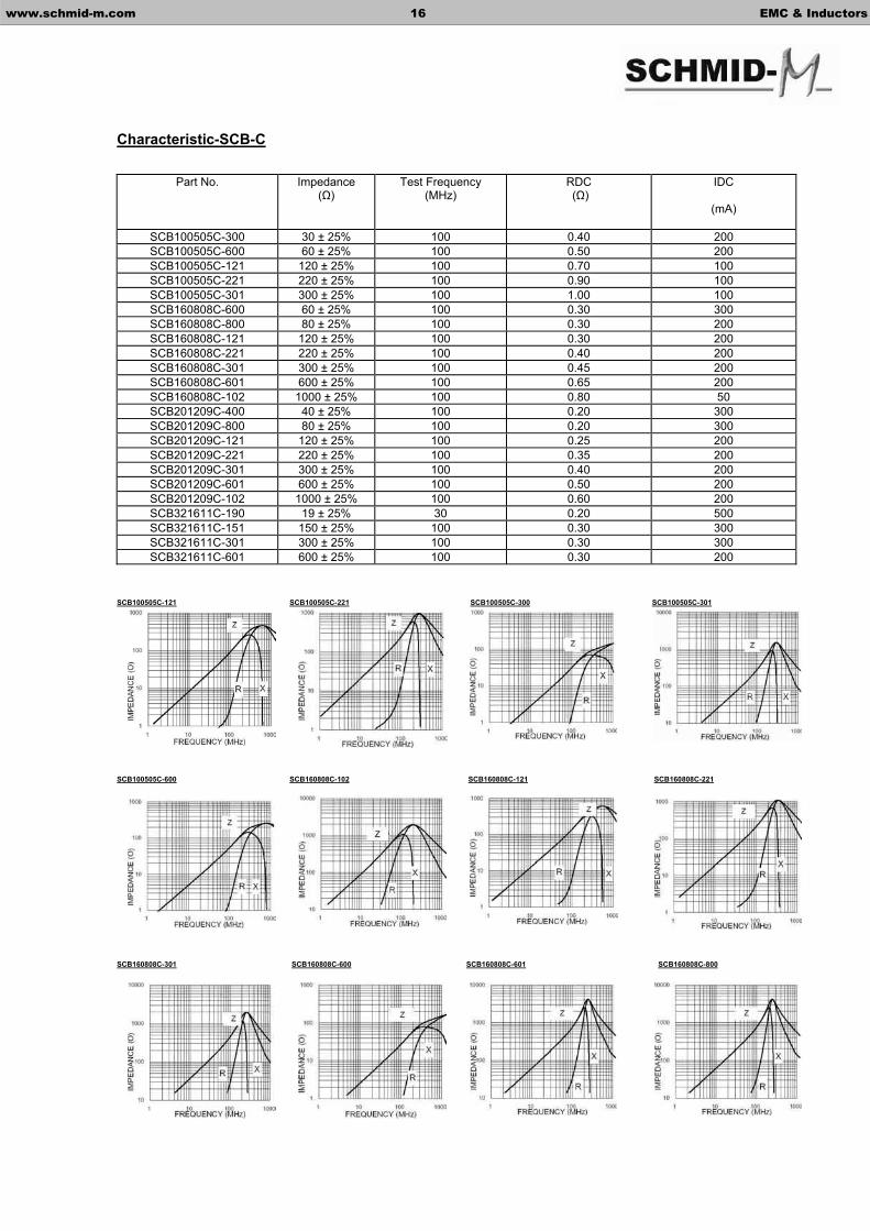
Characteristic-SCB-C
SCB100505C-121 SCB100505C-221 SCB100505C-300 SCB100505C-301
SCB100505C-600 SCB160808C-102 SCB160808C-121 SCB160808C-221
SCB160808C-301 SCB160808C-600 SCB160808C-601 SCB160808C-800
Part No. Impedance ( )
Test Frequency (MHz)
RDC ( )
IDC
(mA)
SCB100505C-300 30 ± 25% 100 0.40 200 SCB100505C-600 60 ± 25% 100 0.50 200 SCB100505C-121 120 ± 25% 100 0.70 100 SCB100505C-221 220 ± 25% 100 0.90 100 SCB100505C-301 300 ± 25% 100 1.00 100 SCB160808C-600 60 ± 25% 100 0.30 300 SCB160808C-800 80 ± 25% 100 0.30 200 SCB160808C-121 120 ± 25% 100 0.30 200 SCB160808C-221 220 ± 25% 100 0.40 200 SCB160808C-301 300 ± 25% 100 0.45 200 SCB160808C-601 600 ± 25% 100 0.65 200 SCB160808C-102 1000 ± 25% 100 0.80 50 SCB201209C-400 40 ± 25% 100 0.20 300 SCB201209C-800 80 ± 25% 100 0.20 300 SCB201209C-121 120 ± 25% 100 0.25 200 SCB201209C-221 220 ± 25% 100 0.35 200 SCB201209C-301 300 ± 25% 100 0.40 200 SCB201209C-601 600 ± 25% 100 0.50 200 SCB201209C-102 1000 ± 25% 100 0.60 200 SCB321611C-190 19 ± 25% 30 0.20 500 SCB321611C-151 150 ± 25% 100 0.30 300 SCB321611C-301 300 ± 25% 100 0.30 300 SCB321611C-601 600 ± 25% 100 0.30 200
www.schmid-m.com 16 EMC & Inductors

SCB201209C-102 SCB201209C-121 SCB201209C-221 SCB201209C-301
SCB201209C-400 SCB201209C-601 SCB201209C-800 SCB321611C-151
SCB321611C-190 SCB321611C-301 SCB321611C-601
www.schmid-m.com 17 EMC & Inductors

Features Dimensions
- SCA series consists of 4 ciruits- SCA series is suitable for EMI suppression in small digital equipment - Excellent solderability and resistance to soldering heat - Closed magnetic circuit avoids crosstalk
Ordering Information
SCA 3216 K 4-121
Characteristics
Part No. Impedance ( )
Test Frequency (MHz)
DC Resistance ( )Max.
Rated Current (mA)Max.
SCA3216K4-300 30 ± 25% 100 0.10 200 SCA3216K4-600 60 ± 25% 100 0.25 200 SCA3216K4-121 120 ± 25% 100 0.30 150 SCA3216K4-221 220 ± 25% 100 0.30 150 SCA3216K4-301 300 ± 25% 100 0.40 150 SCA3216K4-601 600 ± 25% 100 0.50 100 SCA3216K4-102 1000 ± 25% 100 0.70 50 SCA3216M4-121 120 ± 25% 100 0.40 150 SCA3216M4-221 220 ± 25% 100 0.45 150 SCA3216M4-301 300 ± 25% 100 0.50 150 SCA3216M4-471 470 ± 25% 100 0.55 100 SCA3216M4-601 600 ± 25% 100 0.65 100
www.schmid-m.com 18 EMC & Inductors
SMD Chip Bead Array – SCA Series
Impedance Value
4 Electrode PairsMaterial Code Dimensions
Series
Part No. A B C D D1
SCA3216 3.2 ± 0.2 1.6 ± 0.2 0.8 ± 0.2 0.4 ± 0.2 0.4 ± 0.2
D2 P
0.3 ± 0.2 0.8 ± 0.1
QTY/REEL 3000pcs.

SCA3216K4-121 SCA3216K4-102 SCA3216M4-121
SCA3216K4-301 SCA3216K4-600 SCA3216K4-601
SCA3216M4-221 SCA3216M4-301 SCA3216M4-47
SCA3216K4-300 SCA3216K4-221 SCA3216M4-601
www.schmid-m.com 19 EMC & Inductors

Features Package
- Employ high-performance ferrites with superior frequency R – Reel 5000pcs./Reel characteristics M – Box 2000pcs./Box - prevents intrusion and radiation of unnecessary signals into Z – Ammo Pack the clock pulse os-cillation section. Prevents spike noise B – Bulk
Ordering Information
SFBS 13 – 350860 – T5 - R
CharacteristicsImpedance
( ) min Part No. Lead
Configuration
25MHz 100MHz
Curve
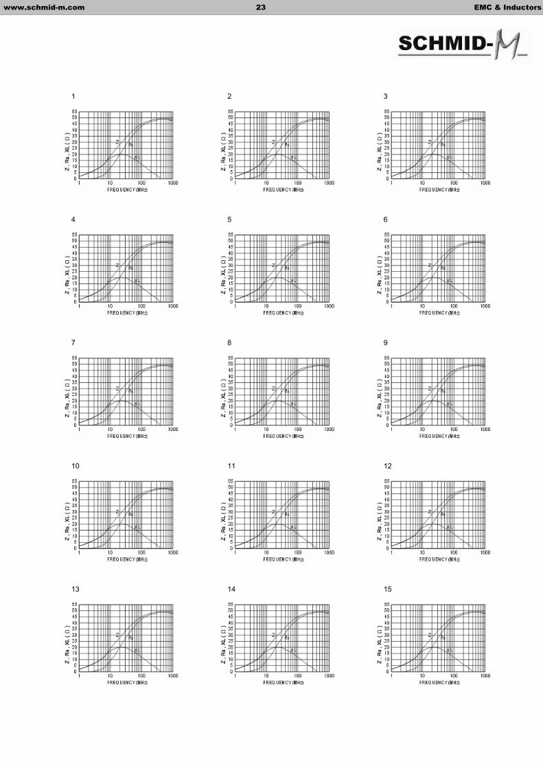
SFBS13-250845 32 50 1
SFBS13-350830 25 45 2
SFBS13-350847 35 60 3
SFBS13-350860 45 72 4
SFBS13-350875 60 120 5
SFBS13-350880 75 123 6
SFBS13-350883 62 125 7
SFBS13-350890
T5,T2,VT, RT,UT,
VB,RB,UB,ST FD,FE,FF
50 93 8
SFBD13-350847 70 110 9
SFBD13-350860 90 150 10
SFBD13-350875 135 218 11
SFBD13-350883 124 240 12
SFBD13-350883 108 235 13
SFBD13-350890
WT,WB
150 250 14
SFBR13-235575 ST,SB 80 150 15
Packaging
Lead Configuration
Dimensions
Design
Series
www.schmid-m.com 20 EMC & Inductors
Ferrite Bead – SFB Series

Dimensions
www.schmid-m.com 21 EMC & Inductors
Part No. A D E d lSFBS13-250845-ST 2.5 ± 0.15 4.5 ± 0.3 2.0 max. SFBS13-350847-ST 3.5 ± 0.15 4.7 ± 0.3 2.0 max. SFBS13-350860-ST 3.5 ± 0.15 6.0 ± 0.3 2.5 max. SFBS13-350890-ST 3.5 ± 0.15 9.0 ± 0.4 2.5 max.
0.65 ± 0.05 18.0 min.
Part No. A D P d lSFBS13-350847-VB 3.5 ± 0.15 4.7 ± 0.3 5.0 ± 1.0 0.6 ± 0.05 9.0 max.
Part No. A D P d lSFBS13-350847-RB 3.5 ± 0.15 4.7 ± 0.3 5.0 ± 1.0 12.5 max. SFBS13-350860-RB 3.5 ± 0.15 6.0 ± 0.3 5.0 ± 1.0 12.5 max. SFBS13-350890-RB 3.5 ± 0.15 9.0 ± 0.3 5.0 ± 1.0
0.65 ± 0.05 16.0 max.
Part No. A D P d lSFBS13-250845-UB 2.5 ± 0.15 4.5 ± 0.3 5.0 ± 1.0 9.0 max. SFBS13-350847-UB 3.5 ± 0.15 4.7 ± 0.3 5.0 ± 1.0
0.65 ± 0.05 9.0 max.
www.schmid-m.com 22 EMC & Inductors
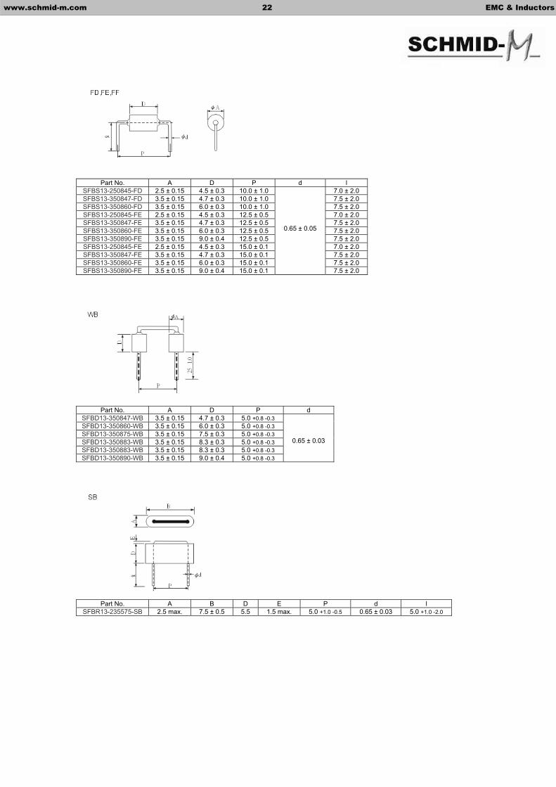
Part No. A D P d lSFBS13-250845-FD 2.5 ± 0.15 4.5 ± 0.3 10.0 ± 1.0 7.0 ± 2.0 SFBS13-350847-FD 3.5 ± 0.15 4.7 ± 0.3 10.0 ± 1.0 7.5 ± 2.0 SFBS13-350860-FD 3.5 ± 0.15 6.0 ± 0.3 10.0 ± 1.0 7.5 ± 2.0 SFBS13-250845-FE 2.5 ± 0.15 4.5 ± 0.3 12.5 ± 0.5 7.0 ± 2.0 SFBS13-350847-FE 3.5 ± 0.15 4.7 ± 0.3 12.5 ± 0.5 7.5 ± 2.0 SFBS13-350860-FE 3.5 ± 0.15 6.0 ± 0.3 12.5 ± 0.5 7.5 ± 2.0 SFBS13-350890-FE 3.5 ± 0.15 9.0 ± 0.4 12.5 ± 0.5 7.5 ± 2.0 SFBS13-250845-FE 2.5 ± 0.15 4.5 ± 0.3 15.0 ± 0.1 7.0 ± 2.0 SFBS13-350847-FE 3.5 ± 0.15 4.7 ± 0.3 15.0 ± 0.1 7.5 ± 2.0 SFBS13-350860-FE 3.5 ± 0.15 6.0 ± 0.3 15.0 ± 0.1 7.5 ± 2.0 SFBS13-350890-FE 3.5 ± 0.15 9.0 ± 0.4 15.0 ± 0.1
0.65 ± 0.05
7.5 ± 2.0
Part No. A D P d SFBD13-350847-WB 3.5 ± 0.15 4.7 ± 0.3 5.0 +0.8 -0.3SFBD13-350860-WB 3.5 ± 0.15 6.0 ± 0.3 5.0 +0.8 -0.3SFBD13-350875-WB 3.5 ± 0.15 7.5 ± 0.3 5.0 +0.8 -0.3SFBD13-350883-WB 3.5 ± 0.15 8.3 ± 0.3 5.0 +0.8 -0.3SFBD13-350883-WB 3.5 ± 0.15 8.3 ± 0.3 5.0 +0.8 -0.3SFBD13-350890-WB 3.5 ± 0.15 9.0 ± 0.4 5.0 +0.8 -0.3
0.65 ± 0.03
Part No. A B D E P d l SFBR13-235575-SB 2.5 max. 7.5 ± 0.5 5.5 1.5 max. 5.0 +1.0 -0.5 0.65 ± 0.03 5.0 +1.0 -2.0
1 2 3
4 5 6
7 8 9
10 11 12
13 14 15
www.schmid-m.com 23 EMC & Inductors

Features
- Supplied taped and reeled per EIA standard - Applications: Computer disk drive and PC board to filter the EMI from outside source. Car radio, mobile phone.
Ordering Information
SSMB 03-562545 –2H
Characteristics
Impedance( ) min
Part No. Shape A B D
25MHz 100MHz
Curve
SSMB13-302540 1 3.18 2.67 4.0 ± 0.25 24 36 1
SSMB12-302585 1 3.18 2.67 8.5 ± 0.25 48 72 2
SSMB03-472976 2 5.0 +0 -0.5 3.45 +0 -0.3 7.6 ± 0.1 60 90 3
SSMB13-472976 2 5.0 +0 -0.5 3.45 +0 -0.3 7.6 ± 0.1 58 80 4
SSMB13-562540-2H 3 5.6 ± 0.2 2.5 ± 0.2 4.0 ± 0.25 22 35 5
SSMB03-562545-2H 3 5.6 ± 0.2 2.5 ± 0.2 4.5 ± 0.25 24 36 6
SSMB04-562545-2H 3 5.6 ± 0.2 2.5 ± 0.2 4.5 ± 0.25 18 36 7
SSMB50-562545-2H 3 5.6 ± 0.2 2.5 ± 0.2 4.5 ± 0.25 24 32 8
SSMB47-562585-2H 3 5.6 ± 0.2 2.5 ± 0.2 8.5 ± 0.25 24 35 9
SSMB47-572685-1H2W 4 5.7 +0.1 -0.5 2.6 +0.1 -0.2 8.47 ± 0.1 48 70 10
SSMB47-562540-2H 3 6.0 ± 0.2 2.5 ± 0.2 4.0 ± 0.25 24 35 11
2 Hole
Dimensions
Design
Series
www.schmid-m.com 24 EMC & Inductors
SMD Common Mode Bead –SSMB Series
Shapes
1 2
3 4

www.schmid-m.com 25 EMC & Inductors
1 2 3
4 5 6
7 8 9
10 11
Features Dimensions
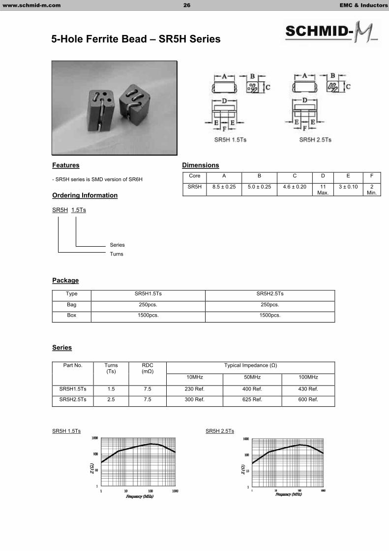
- SR5H series is SMD version of SR6H
Ordering Information
SR5H 1.5Ts
Package
Type SR5H1.5Ts SR5H2.5Ts
Bag 250pcs. 250pcs.
Box 1500pcs. 1500pcs.
Series
Typical Impedance ( )Part No. Turns (Ts)
RDC(m )
10MHz 50MHz 100MHz
SR5H1.5Ts 1.5 7.5 230 Ref. 400 Ref. 430 Ref.
SR5H2.5Ts 2.5 7.5 300 Ref. 625 Ref. 600 Ref.
SR5H 1.5Ts SR5H 2.5Ts
Series
Turns
www.schmid-m.com 26 EMC & Inductors
5-Hole Ferrite Bead – SR5H Series
Core A B C D E F
SR5H 8.5 ± 0.25 5.0 ± 0.25 4.6 ± 0.20 11 Max.
3 ± 0.10 2 Min.

Features
- Compact, medium current, high impedance EMI suppression component - Wide Band Coke used in PC products to filter EMI
Ordering Information
SR6H – 1.5Ts
Dimensions
Core A B C D
SR6H 6x10 6.0 ± 0.25 10.0 ± 0.30 0.9 ± 0.15 0.5 ± 0.05
Turns 1.5Ts 2Ts 2.5Ts 3Ts 1.5Ts X2 2.5Ts U 3Ts U
Package Bulk: 250pcs. / Bag; 1 Box = 6 Bags (1500pcs.)
Shapes
1.5Ts 2Ts 2.5Ts 3Ts 1.5Ts x2
2.5Ts U 3Ts U
Turns
Series
www.schmid-m.com 27 EMC & Inductors
6-Hole Ferrite Bead – SR6H Series

Characteristics
A6 SR6H 2.5Ts K5B SR6H 1.0Ts K5B SR6H 1.5Ts
K5B SR6H 1.5Tsx2 K5B SR6H 2.0Ts K5B SR6H 2.5Ts
K5B SR6H 3.0Ts
Typcial Impedance ( )
Part No. Turns (Ts)
10MHz (min) 25MHz (min) 100MHz (min)
SR6H1.0Ts 1.0 58 182 233
SR6H1.5Ts 1.5 170 320 375
SR6H2.0Ts 2.0 240 520 480
SR6H2.5Ts 2.5 320 680 580
SR6H2.5Ts 2.5 400 680 580
SR6H3.0Ts 3.0 400 800 550
SR6H1.5Tsx2 1.5x2 170 320 375
www.schmid-m.com 28 EMC & Inductors
6-Hole Ferrite Bead – SR6H Series
Features Dimensions
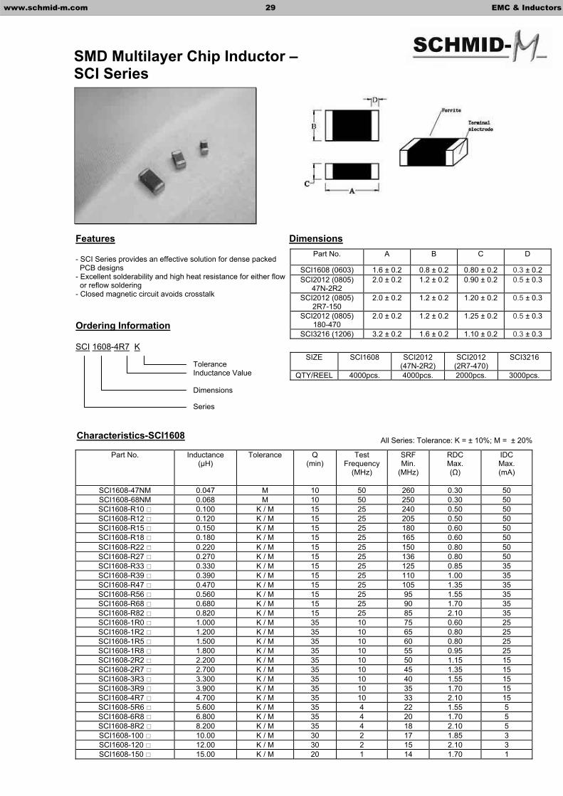
- SCI Series provides an effective solution for dense packed PCB designs - Excellent solderability and high heat resistance for either flow or reflow soldering - Closed magnetic circuit avoids crosstalk
Ordering Information
SCI 1608-4R7 K
Characteristics-SCI1608
Part No. Inductance (µH)
Tolerance Q (min)
Test Frequency
(MHz)
SRFMin.
(MHz)
RDCMax. ( )
IDCMax. (mA)
SCI1608-47NM 0.047 M 10 50 260 0.30 50 SCI1608-68NM 0.068 M 10 50 250 0.30 50 SCI1608-R10 0.100 K / M 15 25 240 0.50 50 SCI1608-R12 0.120 K / M 15 25 205 0.50 50 SCI1608-R15 0.150 K / M 15 25 180 0.60 50 SCI1608-R18 0.180 K / M 15 25 165 0.60 50 SCI1608-R22 0.220 K / M 15 25 150 0.80 50 SCI1608-R27 0.270 K / M 15 25 136 0.80 50 SCI1608-R33 0.330 K / M 15 25 125 0.85 35 SCI1608-R39 0.390 K / M 15 25 110 1.00 35 SCI1608-R47 0.470 K / M 15 25 105 1.35 35 SCI1608-R56 0.560 K / M 15 25 95 1.55 35 SCI1608-R68 0.680 K / M 15 25 90 1.70 35 SCI1608-R82 0.820 K / M 15 25 85 2.10 35 SCI1608-1R0 1.000 K / M 35 10 75 0.60 25 SCI1608-1R2 1.200 K / M 35 10 65 0.80 25 SCI1608-1R5 1.500 K / M 35 10 60 0.80 25 SCI1608-1R8 1.800 K / M 35 10 55 0.95 25 SCI1608-2R2 2.200 K / M 35 10 50 1.15 15 SCI1608-2R7 2.700 K / M 35 10 45 1.35 15 SCI1608-3R3 3.300 K / M 35 10 40 1.55 15 SCI1608-3R9 3.900 K / M 35 10 35 1.70 15 SCI1608-4R7 4.700 K / M 35 10 33 2.10 15 SCI1608-5R6 5.600 K / M 35 4 22 1.55 5 SCI1608-6R8 6.800 K / M 35 4 20 1.70 5 SCI1608-8R2 8.200 K / M 35 4 18 2.10 5 SCI1608-100 10.00 K / M 30 2 17 1.85 3 SCI1608-120 12.00 K / M 30 2 15 2.10 3 SCI1608-150 15.00 K / M 20 1 14 1.70 1
ToleranceInductance Value
Dimensions
Series
www.schmid-m.com 29 EMC & Inductors
SMD Multilayer Chip Inductor – SCI Series
Part No. A B C D
SCI1608 (0603) 1.6 ± 0.2 0.8 ± 0.2 0.80 ± 0.2 0.3 ± 0.2SCI2012 (0805)
47N-2R2 2.0 ± 0.2 1.2 ± 0.2 0.90 ± 0.2 0.5 ± 0.3
SCI2012 (0805) 2R7-150
2.0 ± 0.2 1.2 ± 0.2 1.20 ± 0.2 0.5 ± 0.3
SCI2012 (0805) 180-470
2.0 ± 0.2 1.2 ± 0.2 1.25 ± 0.2 0.5 ± 0.3
SCI3216 (1206) 3.2 ± 0.2 1.6 ± 0.2 1.10 ± 0.2 0.3 ± 0.3
SIZE SCI1608 SCI2012 (47N-2R2)
SCI2012(2R7-470)
SCI3216
QTY/REEL 4000pcs. 4000pcs. 2000pcs. 3000pcs.
All Series: Tolerance: K = ± 10%; M = ± 20%

Characteristics-SCI1608
www.schmid-m.com 30 EMC & Inductors

Characteristics-SCI2012Part No. Inductance
(µH)Tolerance Thickness
(mm)Q
(min) Test
Frequency (MHz)
SRFMin.
(MHz)
RDCMax. ( )
IDCMax. (mA)
SCI2012-47NM 0.047 M 0.90 ± 0.2 15 50 320 0.20 300 SCI2012-68NM 0.068 M 0.90 ± 0.2 15 50 280 0.20 300 SCI2012-R10 0.100 K / M 0.90 ± 0.2 20 25 235 0.30 250 SCI2012-R12 0.120 K / M 0.90 ± 0.2 20 25 220 0.30 250 SCI2012-R15 0.150 K / M 0.90 ± 0.2 20 25 200 0.40 250 SCI2012-R18 0.180 K / M 0.90 ± 0.2 20 25 185 0.40 250 SCI2012-R22 0.220 K / M 0.90 ± 0.2 20 25 170 0.50 250 SCI2012-R27 0.270 K / M 0.90 ± 0.2 20 25 150 0.50 250 SCI2012-R33 0.330 K / M 0.90 ± 0.2 20 25 145 0.55 250 SCI2012-R39 0.390 K / M 0.90 ± 0.2 25 25 135 0.65 200 SCI2012-R47 0.470 K / M 0.90 ± 0.2 25 25 125 0.65 200 SCI2012-R56 0.560 K / M 0.90 ± 0.2 25 25 115 0.75 150 SCI2012-R68 0.680 K / M 0.90 ± 0.2 25 25 105 0.80 150 SCI2012-R82 0.820 K / M 0.90 ± 0.2 25 25 100 1.00 150 SCI2012-1R0 1.000 K / M 0.90 ± 0.2 45 10 75 0.40 50 SCI2012-1R2 1.200 K / M 0.90 ± 0.2 45 10 65 0.50 50 SCI2012-1R5 1.500 K / M 0.90 ± 0.2 45 10 60 0.50 50 SCI2012-1R8 1.800 K / M 0.90 ± 0.2 45 10 55 0.60 50 SCI2012-2R2 2.200 K / M 0.90 ± 0.2 45 10 50 0.65 30 SCI2012-2R7 2.700 K / M 1.20 ± 0.2 45 10 45 0.75 30 SCI2012-3R3 3.300 K / M 1.20 ± 0.2 45 10 41 0.80 30 SCI2012-3R9 3.900 K / M 1.20 ± 0.2 45 10 38 0.90 30 SCI2012-4R7 4.700 K / M 1.20 ± 0.2 45 10 35 1.00 30 SCI2012-5R6 5.600 K / M 1.20 ± 0.2 50 4.0 32 0.90 15 SCI2012-6R8 6.800 K / M 1.20 ± 0.2 50 4.0 29 1.00 15 SCI2012-8R2 8.200 K / M 1.20 ± 0.2 50 2.0 26 1.10 15 SCI2012-100 10.00 K / M 1.20 ± 0.2 50 2.0 24 1.15 15 SCI2012-120 12.00 K / M 1.20 ± 0.2 50 2.0 22 1.25 15 SCI2012-150 15.00 K / M 1.20 ± 0.2 30 1.0 19 0.80 5 SCI2012-180 18.00 K / M 1.25 ± 0.2 30 1.0 18 0.90 5 SCI2012-220 22.00 K / M 1.25 ± 0.2 30 1.0 16 1.10 5 SCI2012-270 27.00 K / M 1.25 ± 0.2 30 1.0 14 1.15 5 SCI2012-330 33.00 K / M 1.25 ± 0.2 30 0.4 13 1.25 5 SCI2012-390 39.00 K / M 1.25 ± 0.2 35 1.0 8 2.90 4 SCI2012-470 47.00 K / M 1.25 ± 0.2 35 1.0 8 3.00 4
www.schmid-m.com 31 EMC & Inductors
Please note SCI2012 Series thickness, there are three types of thickness in this series.

Characteristics-SCI3216Part No. Inductance
(µH)Tolerance Q
(min) Test
Frequency (MHz)
SRFMin.
(MHz)
RDCMax. ( )
IDCMax. (mA)
SCI3216-47NM 0.047 M 20 50 320 0.15 300 SCI3216-68NM 0.068 M 20 50 280 0.25 300 SCI3216-R10 0.100 K / M 20 25 235 0.25 250 SCI3216-R12 0.120 K / M 20 25 220 0.30 250 SCI3216-R15 0.150 K / M 20 25 200 0.30 250 SCI3216-R18 0.180 K / M 20 25 185 0.40 250 SCI3216-R22 0.220 K / M 20 25 170 0.40 250 SCI3216-R27 0.270 K / M 20 25 150 0.50 250 SCI3216-R33 0.330 K / M 20 25 145 0.60 250 SCI3216-R39 0.390 K / M 25 25 135 0.50 200 SCI3216-R47 0.470 K / M 25 25 125 0.60 200 SCI3216-R56 0.560 K / M 25 25 115 0.70 150 SCI3216-R68 0.680 K / M 25 25 105 0.80 150 SCI3216-R82 0.820 K / M 25 25 100 0.90 150 SCI3216-1R0 1.000 K / M 45 10 75 0.40 100 SCI3216-1R2 1.200 K / M 45 10 65 0.50 100 SCI3216-1R5 1.500 K / M 45 10 60 0.50 50 SCI3216-1R8 1.800 K / M 45 10 55 0.50 50 SCI3216-2R2 2.200 K / M 45 10 50 0.60 50 SCI3216-2R7 2.700 K / M 45 10 45 0.60 50 SCI3216-3R3 3.300 K / M 45 10 41 0.70 50 SCI3216-3R9 3.900 K / M 45 10 38 0.80 50 SCI3216-4R7 4.700 K / M 45 10 35 0.90 50 SCI3216-5R6 5.600 K / M 50 4.0 32 0.70 25 SCI3216-6R8 6.800 K / M 50 4.0 29 0.80 25 SCI3216-8R2 8.200 K / M 50 4.0 26 0.90 25 SCI3216-100 10.00 K / M 50 2.0 24 1.00 25 SCI3216-120 12.00 K / M 50 2.0 22 1.05 15 SCI3216-150 15.00 K / M 35 1.0 19 0.70 5 SCI3216-180 18.00 K / M 35 1.0 18 0.70 5 SCI3216-220 22.00 K / M 35 1.0 16 0.90 5 SCI3216-270 27.00 K / M 35 1.0 14 0.90 5 SCI3216-330 33.00 K / M 35 1.0 13 1.05 5 SCI3216-390 39.00 K / M 40 2.0 11 3.00 10 SCI3216-470 47.00 K / M 40 2.0 10 3.40 10 SCI3216-560 56.00 K / M 40 2.0 9.5 3.80 10
www.schmid-m.com 32 EMC & Inductors

Features Dimensions
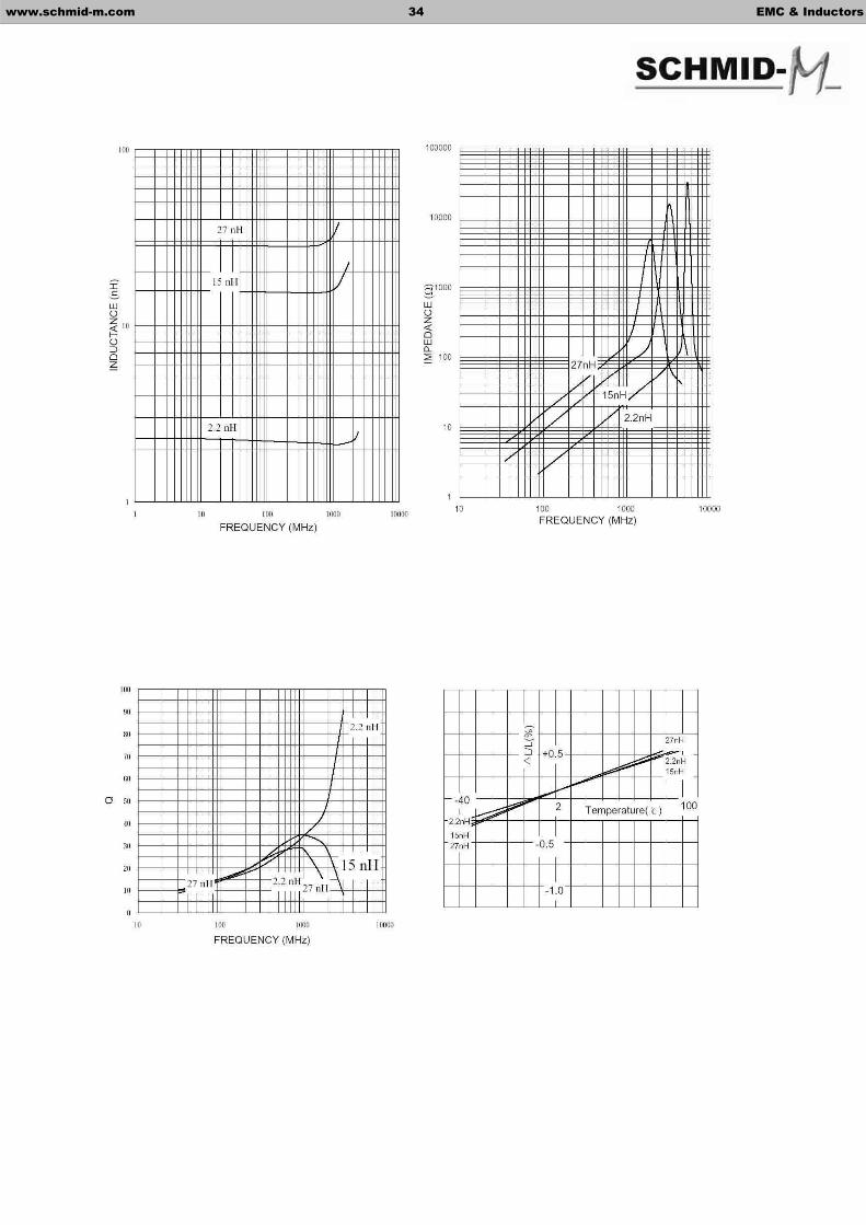
- Miscellaneous high-frequency circuits - EMI countermeasure in high-frequency circuits - High SRF up to 6GHz and above
Ordering Information
SCI 1005C-4N7 K
Characteristics-SCI1005C
Q Typical Part No. Inductance (nH)
@100MHz
Tolerance
100MHz
800MHz
SRFMin.
(MHz)
RDCMax. ( )
IDCMax. (mA)
SCI1005C-1N0S 1.0 S 10 28 13500 0.10 300 SCI1005C-1N2S 1.2 S 9 28 12000 0.10 300 SCI1005C-1N5S 1.5 S 10 30 10500 0.10 300 SCI1005C-1N8S 1.8 S 10 28 9400 0.10 300 SCI1005C-2N2S 2.2 S 10 30 8700 0.20 300 SCI1005C-2N7S 2.7 S 10 30 7700 0.20 300 SCI1005C-3N3 3.3 S / K 10 30 6800 0.30 300 SCI1005C-3N9 3.9 S / K 11 31 6300 0.30 300 SCI1005C-4N7 4.7 S / K 10 30 5700 0.40 300 SCI1005C-5N6 5.6 S / K 11 31 5100 0.40 300 SCI1005C-6N8 6.8 J / K 10 31 4550 0.50 300 SCI1005C-8N2 8.2 J / K 12 34 4100 0.50 300 SCI1005C-10N 10.0 J / K 12 32 3750 0.60 300 SCI1005C-12N 12.0 J / K 12 31 2950 0.60 300 SCI1005C-15N 15.0 J / K 11 30 2600 0.70 300 SCI1005C-18N 18.0 J / K 11 29 2350 0.80 300 SCI1005C-22N 22.0 J / K 11 28 1950 0.90 300 SCI1005C-27N 27.0 J / K 12 27 1750 1.00 300 SCI1005C-33N 33.0 J / K 10 25 1700 1.50 200 SCI1005C-39N 39.0 J / K 10 25 1650 1.80 200 SCI1005C-47N 47.0 J / K 9 23 1300 2.00 200
ToleranceInductance Value
Dimensions
Series
www.schmid-m.com 33 EMC & Inductors
SMD RF Multilayer Chip Inductor – SCI-C Series
Part No. A B C D
SCI1005C (0402) 1.0 ± 0.1 0.5 ± 0.1 0.5 ± 0.1 0.1 Min
SCI1608C (0603) 1.6 ± 0.2 0.8 ± 0.2 0.8 ± 0.2 0.3 ± 0.2
SCI2012C (0805) 2.0 ± 0.2 1.2 ± 0.2 0.9 ± 0.2 0.5 ± 0.2
SIZE SCI1005C SCI1608C SCI2012C
QTY/REEL 10000pcs. 4000pcs. 4000pcs.
All Series: Tolerance: S = ± 0.3nH; J = ± 5%, K = ± 10%
www.schmid-m.com 34 EMC & Inductors

Characteristics-SCI1608CQ Typical Part No. Inductance
(nH)@100MHz
Tolerance
100MHz
800MHz
SRFMin.
(MHz)
RDCMax. ( )
IDCMax. (mA)
SCI1608C-1N2S 1.2 S 13 60 >6000 0.10 300 SCI1608C-1N5S 1.5 S 13 47 >6000 0.10 300 SCI1608C-1N8S 1.8 S 12 51 >6000 0.12 300 SCI1608C-2N2S 2.2 S 12 38 >6000 0.16 300 SCI1608C-2N7S 2.7 S 12 38 >6000 0.20 300 SCI1608C-3N3 3.3 S / K 12 41 5700 0.22 300 SCI1608C-3N9 3.9 S / K 13 50 5600 0.25 300 SCI1608C-4N7 4.7 S / K 12 41 4800 0.28 300 SCI1608C-5N6 5.6 S / K 12 42 4350 0.29 300 SCI1608C-6N8 6.8 J / K 12 40 3750 0.30 300 SCI1608C-8N2 8.2 J / K 13 34 3300 0.33 300 SCI1608C-10N 10.0 J / K 13 45 2850 0.35 300 SCI1608C-12N 12.0 J / K 15 46 2700 0.40 300 SCI1608C-15N 15.0 J / K 15 48 2400 0.45 300 SCI1608C-18N 18.0 J / K 16 48 2050 0.50 300 SCI1608C-22N 22.0 J / K 17 45 1850 0.55 300 SCI1608C-27N 27.0 J / K 17 43 1750 0.60 300 SCI1608C-33N 33.0 J / K 18 39 1500 0.65 300 SCI1608C-39N 39.0 J / K 17 37 1350 0.70 300 SCI1608C-47N 47.0 J / K 17 35 1200 0.90 300 SCI1608C-56N 56.0 J / K 17 32 1100 1.00 300 SCI1608C-68N 68.0 J / K 18 34 1000 1.50 300 SCI1608C-82N 82.0 J / K 18 32 900 1.80 300 SCI1608C-R10 100.0 J / K 15 16 830 2.10 300
www.schmid-m.com 35 EMC & Inductors

Characteristics-SCI2012CQ Typical Part No. Inductance
(nH)@100MHz
Tolerance
100MHz
800MHz
SRFMin.
(MHz)
RDCMax. ( )
IDCMax. (mA)
SCI2012C-1N5S 1.5 S 13 40 >6000 0.10 300 SCI2012C-1N8S 1.8 S 13 45 >6000 0.10 300 SCI2012C-2N2S 2.2 S 13 48 >6000 0.10 300 SCI2012C-2N7S 2.7 S 12 36 >6000 0.10 300 SCI2012C-3N3 3.3 S / K 13 56 >6000 0.13 300 SCI2012C-3N9 3.9 S / K 15 54 5400 0.15 300 SCI2012C-4N7 4.7 S / K 15 50 4500 0.20 300 SCI2012C-5N6 5.6 S / K 15 53 4000 0.23 300 SCI2012C-6N8 6.8 J / K 15 51 3650 0.25 300 SCI2012C-8N2 8.2 J / K 15 53 3000 0.28 300 SCI2012C-10N 10.0 J / K 16 45 2500 0.30 300 SCI2012C-12N 12.0 J / K 16 48 2450 0.35 300 SCI2012C-15N 15.0 J / K 17 48 2000 0.40 300 SCI2012C-18N 18.0 J / K 17 43 1750 0.45 300 SCI2012C-22N 22.0 J / K 17 47 1700 0.50 300 SCI2012C-27N 27.0 J / K 18 38 1550 0.55 300 SCI2012C-33N 33.0 J / K 18 35 1350 0.60 300 SCI2012C-39N 39.0 J / K 18 40 1300 0.65 300 SCI2012C-47N 47.0 J / K 18 33 1200 0.70 300 SCI2012C-56N 56.0 J / K 19 31 1150 0.75 300 SCI2012C-68N 68.0 J / K 19 28 1000 0.85 300 SCI2012C-82N 82.0 J / K 20 9 850 0.90 300 SCI2012C-R10 100.0 J / K 18 - 730 1.00 300 SCI2012C-R12 120.0 J / K 19 - 650 1.30 250 SCI2012C-R15 150.0 J / K 20 - 550 1.50 250 SCI2012C-R18 180.0 J / K 20 - 500 1.80 250 SCI2012C-R22 220.0 J / K 20 - 450 2.00 200 SCI2012C-R27 270.0 J / K 20 - 400 2.50 200 SCI2012C-R33 330.0 J / K 20 - 380 3.00 150 SCI2012C-R39 390.0 J / K 20 - 330 3.50 150 SCI2012C-R47 470.0 J / K 19 - 300 4.00 100
www.schmid-m.com 36 EMC & Inductors
Features Dimensions
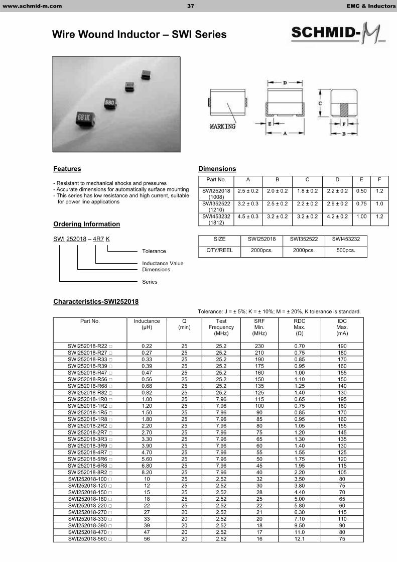
- Resistant to mechanical shocks and pressures - Accurate dimensions for automatically surface mounting - This series has low resistance and high current, suitable for power line applications
Ordering Information
SWI 252018 – 4R7 K
Characteristics-SWI252018
Part No. Inductance (µH)
Q(min)
Test Frequency
(MHz)
SRFMin.
(MHz)
RDCMax. ( )
IDCMax. (mA)
SWI252018-R22 0.22 25 25.2 230 0.70 190 SWI252018-R27 0.27 25 25.2 210 0.75 180 SWI252018-R33 0.33 25 25.2 190 0.85 170 SWI252018-R39 0.39 25 25.2 175 0.95 160 SWI252018-R47 0.47 25 25.2 160 1.00 155 SWI252018-R56 0.56 25 25.2 150 1.10 150 SWI252018-R68 0.68 25 25.2 135 1.25 140 SWI252018-R82 0.82 25 25.2 125 1.40 130 SWI252018-1R0 1.00 25 7.96 115 0.65 195 SWI252018-1R2 1.20 25 7.96 100 0.75 180 SWI252018-1R5 1.50 25 7.96 90 0.85 170 SWI252018-1R8 1.80 25 7.96 85 0.95 160 SWI252018-2R2 2.20 25 7.96 80 1.05 155 SWI252018-2R7 2.70 25 7.96 75 1.20 145 SWI252018-3R3 3.30 25 7.96 65 1.30 135 SWI252018-3R9 3.90 25 7.96 60 1.40 130 SWI252018-4R7 4.70 25 7.96 55 1.55 125 SWI252018-5R6 5.60 25 7.96 50 1.75 120 SWI252018-6R8 6.80 25 7.96 45 1.95 115 SWI252018-8R2 8.20 25 7.96 40 2.20 105 SWI252018-100 10 25 2.52 32 3.50 80 SWI252018-120 12 25 2.52 30 3.80 75 SWI252018-150 15 25 2.52 28 4.40 70 SWI252018-180 18 25 2.52 25 5.00 65 SWI252018-220 22 25 2.52 22 5.80 60 SWI252018-270 27 20 2.52 21 6.30 115 SWI252018-330 33 20 2.52 20 7.10 110 SWI252018-390 39 20 2.52 18 9.50 90 SWI252018-470 47 20 2.52 17 11.0 80 SWI252018-560 56 20 2.52 16 12.1 75
Tolerance
Inductance Value Dimensions
Series
www.schmid-m.com 37 EMC & Inductors
Wire Wound Inductor – SWI Series
Part No. A B C D E F
SWI252018(1008)
2.5 ± 0.2 2.0 ± 0.2 1.8 ± 0.2 2.2 ± 0.2 0.50 1.2
SWI352522(1210)
3.2 ± 0.3 2.5 ± 0.2 2.2 ± 0.2 2.9 ± 0.2 0.75 1.0
SWI453232(1812)
4.5 ± 0.3 3.2 ± 0.2 3.2 ± 0.2 4.2 ± 0.2 1.00 1.2
SIZE SWI252018 SWI352522 SWI453232
QTY/REEL 2000pcs. 2000pcs. 500pcs.
Tolerance: J = ± 5%; K = ± 10%; M = ± 20%, K tolerance is standard.

Characteristics-SWI322522
Characteristics-SWI453232
SWI252018-680 68 20 2.52 15 16.6 70 SWI252018-820 82 20 2.52 13 19.0 65 SWI252018-101 100 15 0.796 12 21.0 60
Part No. Inductance (µH)
Q(min)
Test Frequency
(MHz)
SRFMin.
(MHz)
RDCMax. ( )
IDCMax. (mA)
SWI322522-R12 0.12 30 25.2 500 0.22 450 SWI322522-R15 0.15 30 25.2 450 0.25 450 SWI322522-R18 0.18 30 25.2 400 0.28 450 SWI322522-R22 0.22 30 25.2 350 0.32 450 SWI322522-R27 0.27 30 25.2 320 0.36 450 SWI322522-R33 0.33 30 25.2 300 0.40 450 SWI322522-R39 0.39 30 25.2 250 0.45 450 SWI322522-R47 0.47 30 25.2 220 0.50 450 SWI322522-R56 0.56 30 25.2 180 0.55 450 SWI322522-R68 0.68 30 25.2 160 0.60 450 SWI322522-R82 0.82 30 25.2 140 0.65 450 SWI322522-1R0 1.00 30 7.96 120 0.70 400 SWI322522-1R2 1.20 30 7.96 100 0.75 390 SWI322522-1R5 1.50 30 7.96 85 0.85 370 SWI322522-1R8 1.80 30 7.96 80 0.90 350 SWI322522-2R2 2.20 30 7.96 75 1.00 320 SWI322522-2R7 2.70 30 7.96 70 1.10 290 SWI322522-3R3 3.30 30 7.96 60 1.20 260 SWI322522-3R9 3.90 30 7.96 55 1.30 250 SWI322522-4R7 4.70 30 7.96 50 1.50 220 SWI322522-5R6 5.60 30 7.96 47 1.60 200 SWI322522-6R8 6.80 30 7.96 43 1.80 180 SWI322522-8R2 8.20 30 7.96 40 2.00 170 SWI322522-100 10 30 2.52 36 2.10 150 SWI322522-120 12 30 2.52 33 2.50 140 SWI322522-150 15 30 2.52 28 2.80 130 SWI322522-180 18 30 2.52 25 3.30 120 SWI322522-220 22 30 2.52 23 3.70 110 SWI322522-270 27 30 2.52 18 5.00 80 SWI322522-330 33 30 2.52 17 5.60 70 SWI322522-390 39 30 2.52 16 6.40 65 SWI322522-470 47 30 2.52 15 7.00 60 SWI322522-560 56 30 2.52 13 8.00 55 SWI322522-680 68 30 2.52 12 9.00 50 SWI322522-820 82 30 0.796 11 10.0 45 SWI322522-101 100 20 0.796 10 11.0 40 SWI322522-121 120 20 0.796 10 12.0 70 SWI322522-151 150 20 0.796 8 15.0 65 SWI322522-181 180 20 0.796 7 17.0 60 SWI322522-221 220 20 0.796 7 21.0 60
Part No. Inductance (µH)
Q(min)
Test Frequency
(MHz)
SRFMin.
(MHz)
RDCMax. ( )
IDCMax. (mA)
SWI453232-R10 0.10 35 25.2 300 0.20 800 SWI453232-R12 0.12 35 25.2 280 0.20 770 SWI453232-R15 0.15 35 25.2 250 0.20 730 SWI453232-R18 0.18 35 25.2 200 0.20 700 SWI453232-R22 0.22 40 25.2 220 0.30 665 SWI453232-R27 0.27 40 25.2 180 0.30 635 SWI453232-R33 0.33 40 25.2 165 0.30 605 SWI453232-R39 0.39 40 25.2 150 0.30 575 SWI453232-R47 0.47 40 25.2 145 0.30 545 SWI453232-R56 0.56 40 25.2 140 0.40 520 SWI453232-R68 0.68 40 25.2 135 0.40 500 SWI453232-R82 0.82 40 25.2 130 0.50 475 SWI453232-1R0 1.00 50 7.96 100 0.50 450
www.schmid-m.com 38 EMC & Inductors
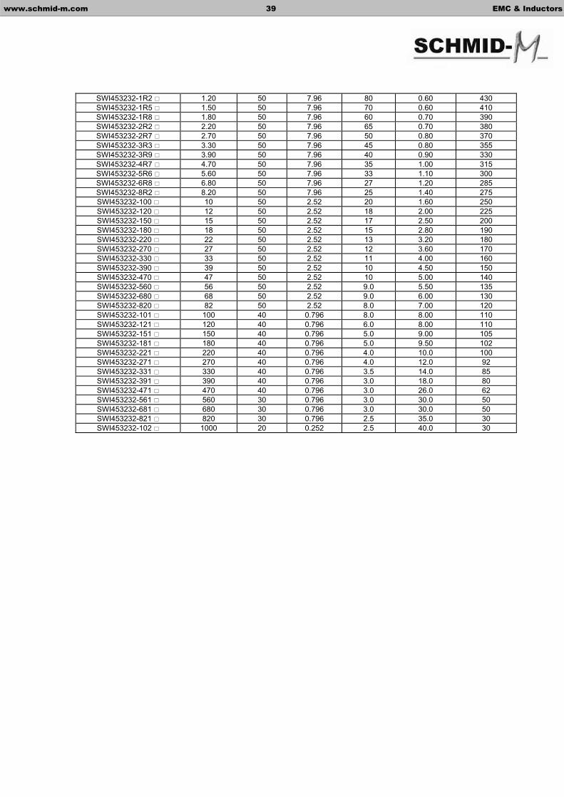
SWI453232-1R2 1.20 50 7.96 80 0.60 430 SWI453232-1R5 1.50 50 7.96 70 0.60 410 SWI453232-1R8 1.80 50 7.96 60 0.70 390 SWI453232-2R2 2.20 50 7.96 65 0.70 380 SWI453232-2R7 2.70 50 7.96 50 0.80 370 SWI453232-3R3 3.30 50 7.96 45 0.80 355 SWI453232-3R9 3.90 50 7.96 40 0.90 330 SWI453232-4R7 4.70 50 7.96 35 1.00 315 SWI453232-5R6 5.60 50 7.96 33 1.10 300 SWI453232-6R8 6.80 50 7.96 27 1.20 285 SWI453232-8R2 8.20 50 7.96 25 1.40 275 SWI453232-100 10 50 2.52 20 1.60 250 SWI453232-120 12 50 2.52 18 2.00 225 SWI453232-150 15 50 2.52 17 2.50 200 SWI453232-180 18 50 2.52 15 2.80 190 SWI453232-220 22 50 2.52 13 3.20 180 SWI453232-270 27 50 2.52 12 3.60 170 SWI453232-330 33 50 2.52 11 4.00 160 SWI453232-390 39 50 2.52 10 4.50 150 SWI453232-470 47 50 2.52 10 5.00 140 SWI453232-560 56 50 2.52 9.0 5.50 135 SWI453232-680 68 50 2.52 9.0 6.00 130 SWI453232-820 82 50 2.52 8.0 7.00 120 SWI453232-101 100 40 0.796 8.0 8.00 110 SWI453232-121 120 40 0.796 6.0 8.00 110 SWI453232-151 150 40 0.796 5.0 9.00 105 SWI453232-181 180 40 0.796 5.0 9.50 102 SWI453232-221 220 40 0.796 4.0 10.0 100 SWI453232-271 270 40 0.796 4.0 12.0 92 SWI453232-331 330 40 0.796 3.5 14.0 85 SWI453232-391 390 40 0.796 3.0 18.0 80 SWI453232-471 470 40 0.796 3.0 26.0 62 SWI453232-561 560 30 0.796 3.0 30.0 50 SWI453232-681 680 30 0.796 3.0 30.0 50 SWI453232-821 820 30 0.796 2.5 35.0 30 SWI453232-102 1000 20 0.252 2.5 40.0 30
www.schmid-m.com 39 EMC & Inductors
Features Dimensions
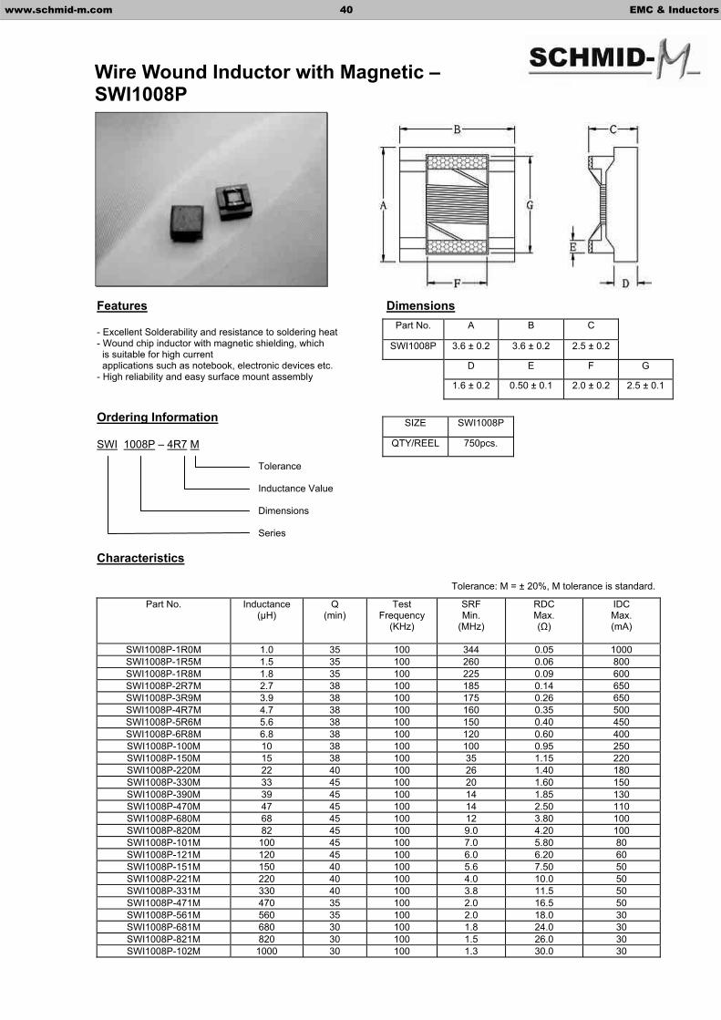
- Excellent Solderability and resistance to soldering heat - Wound chip inductor with magnetic shielding, which is suitable for high current applications such as notebook, electronic devices etc. - High reliability and easy surface mount assembly
Ordering Information
SWI 1008P – 4R7 M
Characteristics
Part No. Inductance (µH)
Q(min)
Test Frequency
(KHz)
SRFMin.
(MHz)
RDCMax. ( )
IDCMax. (mA)
SWI1008P-1R0M 1.0 35 100 344 0.05 1000 SWI1008P-1R5M 1.5 35 100 260 0.06 800 SWI1008P-1R8M 1.8 35 100 225 0.09 600 SWI1008P-2R7M 2.7 38 100 185 0.14 650 SWI1008P-3R9M 3.9 38 100 175 0.26 650 SWI1008P-4R7M 4.7 38 100 160 0.35 500 SWI1008P-5R6M 5.6 38 100 150 0.40 450 SWI1008P-6R8M 6.8 38 100 120 0.60 400 SWI1008P-100M 10 38 100 100 0.95 250 SWI1008P-150M 15 38 100 35 1.15 220 SWI1008P-220M 22 40 100 26 1.40 180 SWI1008P-330M 33 45 100 20 1.60 150 SWI1008P-390M 39 45 100 14 1.85 130 SWI1008P-470M 47 45 100 14 2.50 110 SWI1008P-680M 68 45 100 12 3.80 100 SWI1008P-820M 82 45 100 9.0 4.20 100 SWI1008P-101M 100 45 100 7.0 5.80 80 SWI1008P-121M 120 45 100 6.0 6.20 60 SWI1008P-151M 150 40 100 5.6 7.50 50 SWI1008P-221M 220 40 100 4.0 10.0 50 SWI1008P-331M 330 40 100 3.8 11.5 50 SWI1008P-471M 470 35 100 2.0 16.5 50 SWI1008P-561M 560 35 100 2.0 18.0 30 SWI1008P-681M 680 30 100 1.8 24.0 30 SWI1008P-821M 820 30 100 1.5 26.0 30 SWI1008P-102M 1000 30 100 1.3 30.0 30
Tolerance
Inductance Value
Dimensions
Series
www.schmid-m.com 40 EMC & Inductors
Wire Wound Inductor with Magnetic – SWI1008P
Part No. A B C
SWI1008P 3.6 ± 0.2 3.6 ± 0.2 2.5 ± 0.2
D E F G
1.6 ± 0.2 0.50 ± 0.1 2.0 ± 0.2 2.5 ± 0.1
SIZE SWI1008P
QTY/REEL 750pcs.
Tolerance: M = ± 20%, M tolerance is standard.
Features Dimensions
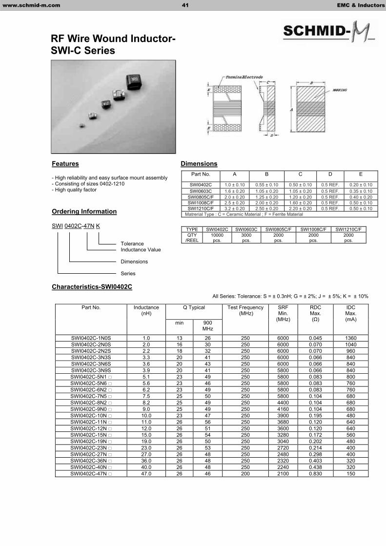
- High reliability and easy surface mount assembly - Consisting of sizes 0402-1210 - High quality factor
Ordering Information
SWI 0402C-47N K
Characteristics-SWI0402C
Q Typical Part No. Inductance (nH)
min 900 MHz
Test Frequency (MHz)
SRFMin.
(MHz)
RDCMax. ( )
IDCMax. (mA)
SWI0402C-1N0S 1.0 13 26 250 6000 0.045 1360 SWI0402C-2N0S 2.0 16 30 250 6000 0.070 1040 SWI0402C-2N2S 2.2 18 32 250 6000 0.070 960 SWI0402C-3N3S 3.3 20 41 250 6000 0.066 840 SWI0402C-3N6S 3.6 20 43 250 6000 0.066 840 SWI0402C-3N9S 3.9 20 41 250 5800 0.066 840 SWI0402C-5N1 5.1 23 49 250 5800 0.083 800 SWI0402C-5N6 5.6 23 46 250 5800 0.083 760 SWI0402C-6N2 6.2 23 49 250 5800 0.083 760 SWI0402C-7N5 7.5 25 50 250 5800 0.104 680 SWI0402C-8N2 8.2 25 49 250 4400 0.104 680 SWI0402C-9N0 9.0 25 49 250 4160 0.104 680 SWI0402C-10N 10.0 23 47 250 3900 0.195 480 SWI0402C-11N 11.0 26 56 250 3680 0.120 640 SWI0402C-12N 12.0 26 51 250 3600 0.120 640 SWI0402C-15N 15.0 26 54 250 3280 0.172 560 SWI0402C-19N 19.0 26 50 250 3040 0.202 480 SWI0402C-23N 23.0 26 53 250 2720 0.214 400 SWI0402C-27N 27.0 26 48 250 2480 0.298 400 SWI0402C-36N 36.0 26 48 250 2320 0.403 320 SWI0402C-40N 40.0 26 48 250 2240 0.438 320 SWI0402C-47N 47.0 26 46 200 2100 0.830 150
ToleranceInductance Value
Dimensions
Series
www.schmid-m.com 41 EMC & Inductors
RF Wire Wound Inductor- SWI-C Series
Part No. A B C D E
SWI0402C 1.0 ± 0.10 0.55 ± 0.10 0.50 ± 0.10 0.5 REF. 0.20 ± 0.10SWI0603C 1.6 ± 0.20 1.05 ± 0.20 1.05 ± 0.20 0.5 REF. 0.35 ± 0.10
SWI0805C/F 2.0 ± 0.20 1.25 ± 0.20 1.20 ± 0.20 0.5 REF. 0.40 ± 0.20SWI1008C/F 2.5 ± 0.20 2.00 ± 0.20 1.60 ± 0.20 0.5 REF. 0.50 ± 0.10SWI1210C/F 3.2 ± 0.20 2.50 ± 0.20 2.20 ± 0.20 0.5 REF. 0.50 ± 0.10
Matrerial Type : C = Ceramic Material ; F = Ferrite Material
TYPE SWI0402C SWI0603C SWI0805C/F SWI1008C/F SWI1210C/F QTY
/REEL10000pcs.
3000pcs.
2000pcs.
2000pcs.
2000pcs.
All Series: Tolerance: S = ± 0.3nH; G = ± 2%; J = ± 5%; K = ± 10%

Characteristics-SWI0603C
Characteristics-SWI0805C
Q Typical Part No. Inductance (nH)
min 900 MHz
Test Frequency (MHz)
SRFMin.
(MHz)
RDCMax. ( )
IDCMax. (mA)
SWI0603C-2N0S 2.0 16 31 250 6900 0.08 700 SWI0603C-3N9S 3.9 22 51 250 6900 0.08 700 SWI0603C-4N7S 4.7 20 47 250 5800 0.11 700 SWI0603C-6N8 6.8 30 63 250 5800 0.11 700 SWI0603C-8N2 8.2 30 72 250 4600 0.10 700 SWI0603C-10N 10 30 66 250 4800 0.13 700 SWI0603C-12N 12 35 72 250 4000 0.13 700 SWI0603C-15N 15 35 68 250 4000 0.17 700 SWI0603C-18N 18 38 77 250 3100 0.17 700 SWI0603C-22N 22 38 70 250 3000 0.22 700 SWI0603C-27N 27 40 75 250 2800 0.22 600 SWI0603C-33N 33 43 78 250 2300 0.22 600 SWI0603C-39N 39 43 66 250 2200 0.25 600 SWI0603C-47N 47 40 65 250 2000 0.28 600 SWI0603C-56N 56 40 66 200 1900 0.31 600 SWI0603C-68N 68 40 57 200 1700 0.34 600 SWI0603C-72N 72 35 60 200 1700 0.49 400 SWI0603C-82N 82 35 58 150 1700 0.54 400 SWI0603C-R10 100 35 51 150 1400 0.63 400 SWI0603C-R12 120 35 45 150 1300 0.65 300 SWI0603C-R15 150 35 33 150 1000 0.92 280 SWI0603C-R18 180 30 26 100 1000 1.25 240 SWI0603C-R22 220 30 23 100 1000 1.70 200 SWI0603C-R27 270 30 10 100 1000 1.80 170
Part No. Inductance (nH)
Q(min)
Test Frequency L
(MHz)
Test Frequency
Q(MHz)
SRFMin.
(MHz)
RDCMax. ( )
IDCMax. (mA)
SWI0805C-2N2S 2.2 50 250 1000 6000 0.06 800 SWI0805C-2N7S 2.7 35 250 1000 6000 0.08 800 SWI0805C-3N3S 3.3 60 250 1000 6000 0.08 800 SWI0805C-3N9S 3.9 60 250 1000 6000 0.06 600 SWI0805C-4N7S 4.7 60 250 1000 5800 0.06 600 SWI0805C-5N6 5.6 60 250 1000 5800 0.08 600 SWI0805C-6N8 6.8 60 250 1000 5500 0.06 600 SWI0805C-8N2 8.2 60 250 1000 5500 0.06 600 SWI0805C-10N 10 60 250 500 4800 0.08 600 SWI0805C-12N 12 60 250 500 4100 0.08 600 SWI0805C-15N 15 60 250 500 3600 0.08 600 SWI0805C-18N 18 60 250 500 3400 0.08 600 SWI0805C-22N 22 60 250 500 3300 0.10 600 SWI0805C-27N 27 60 250 500 2600 0.12 600 SWI0805C-33N 33 60 250 500 2400 0.15 500 SWI0805C-39N 39 60 250 500 2100 0.18 500 SWI0805C-47N 47 60 200 500 1700 0.15 500 SWI0805C-56N 56 60 200 500 1600 0.25 500 SWI0805C-68N 68 60 200 500 1450 0.27 500 SWI0805C-82N 82 60 150 500 1350 0.32 500 SWI0805C-R10 100 60 150 500 1200 0.43 500 SWI0805C-R12 120 50 150 250 1100 0.48 500 SWI0805C-R15 150 50 100 250 950 0.56 400 SWI0805C-R18 180 50 100 250 900 0.78 400 SWI0805C-R22 220 50 100 250 860 1.00 400 SWI0805C-R27 270 45 100 250 850 1.46 350 SWI0805C-R33 330 45 100 250 800 1.65 300 SWI0805C-R39 390 45 100 250 780 2.20 210
www.schmid-m.com 42 EMC & Inductors

Characteristics-SWI1008C
Characteristics-SWI1210C
Part No. Inductance (nH)
Q(min)
Test Frequency L
(MHz)
Test Frequency
Q(MHz)
SRFMin.
(MHz)
RDCMax. ( )
IDCMax. (mA)
SWI1008C-3N3 3.3 50 100 1000 6000 0.06 1000 SWI1008C-6N8 6.8 50 100 1000 5500 0.06 1000 SWI1008C-8N2 8.2 50 100 1000 5500 0.06 1000 SWI1008C-10N 10 50 100 1000 4300 0.08 1000 SWI1008C-12N 12 60 100 500 3600 0.08 1000 SWI1008C-15N 15 60 100 500 2700 0.08 1000 SWI1008C-18N 18 60 100 350 2700 0.10 1000 SWI1008C-22N 22 60 100 350 2500 0.10 1000 SWI1008C-27N 27 60 100 350 1800 0.10 1000 SWI1008C-33N 33 60 100 350 1700 0.10 1000 SWI1008C-39N 39 60 100 350 1500 0.10 1000 SWI1008C-47N 47 60 100 350 1500 0.10 1000 SWI1008C-56N 56 60 100 350 1350 0.12 1000 SWI1008C-68N 68 60 100 350 1300 0.15 1000 SWI1008C-82N 82 60 100 350 1100 0.18 1000 SWI1008C-R10 100 60 100 350 1100 0.18 1000 SWI1008C-R12 120 45 25 100 950 0.20 800 SWI1008C-R15 150 45 25 100 880 0.22 800 SWI1008C-R18 180 45 25 100 800 0.33 800 SWI1008C-R22 220 45 25 100 730 0.45 800 SWI1008C-R27 270 45 25 100 650 0.75 600 SWI1008C-R33 330 45 25 100 570 0.90 500 SWI1008C-R39 390 45 25 100 530 1.06 470 SWI1008C-R47 470 45 25 100 480 1.17 420 SWI1008C-R56 560 45 25 100 430 1.50 310 SWI1008C-R68 680 45 25 100 380 2.06 230 SWI1008C-R75 750 45 25 100 360 2.20 200 SWI1008C-R82 820 45 25 100 350 2.30 180 SWI1008C-R91 910 45 25 100 330 3.18 150 SWI1008C-1R0 1000 35 25 50 310 3.30 120
Part No. Inductance (nH)
Q(min)
Test Frequency L
(MHz)
Test Frequency
Q(MHz)
SRFMin.
(MHz)
RDCMax. ( )
IDCMax. (mA)
SWI1210C-4N7 4.7 50 100 1000 6000 0.06 1000 SWI1210C-5N6 5.6 50 100 1000 5500 0.08 1000 SWI1210C-10N 10 60 100 500 4000 0.06 1000 SWI1210C-12N 12 60 100 500 3400 0.06 1000 SWI1210C-15N 15 60 100 500 3200 0.06 1000 SWI1210C-18N 18 60 100 300 2800 0.06 1000 SWI1210C-22N 22 60 100 300 2300 0.08 1000 SWI1210C-27N 27 60 100 300 2000 0.08 1000 SWI1210C-33N 33 60 100 300 1800 0.08 1000 SWI1210C-39N 39 60 100 300 1800 0.08 1000 SWI1210C-47N 47 60 100 300 1600 0.08 1000 SWI1210C-56N 56 60 100 300 1500 0.10 1000 SWI1210C-68N 68 60 100 300 1300 0.10 1000 SWI1210C-82N 82 60 100 300 1200 0.10 1000 SWI1210C-R10 100 60 100 300 1100 0.10 1000 SWI1210C-R12 120 60 50 300 900 0.12 800 SWI1210C-R15 150 60 50 300 800 0.18 800 SWI1210C-R18 180 60 50 300 760 0.21 800 SWI1210C-R22 220 60 50 300 660 0.27 800 SWI1210C-R27 270 50 50 300 600 0.33 700 SWI1210C-R33 330 50 50 100 550 0.37 650 SWI1210C-R39 390 50 50 100 500 0.63 600 SWI1210C-R47 470 50 50 100 450 0.69 550 SWI1210C-R56 560 50 50 100 400 0.90 450 SWI1210C-R68 680 50 25 100 380 1.05 400 SWI1210C-R82 820 50 25 100 350 1.45 350 SWI1210C-1R0 1000 45 25 100 300 1.90 280 SWI1210C-1R2 1200 45 7.96 50 300 2.20 250 SWI1210C-1R5 1500 45 7.96 50 250 2.43 220 SWI1210C-1R8 1800 45 7.96 50 200 3.36 180 SWI1210C-2R2 2200 40 7.96 50 200 3.50 150
www.schmid-m.com 43 EMC & Inductors
Features Dimensions
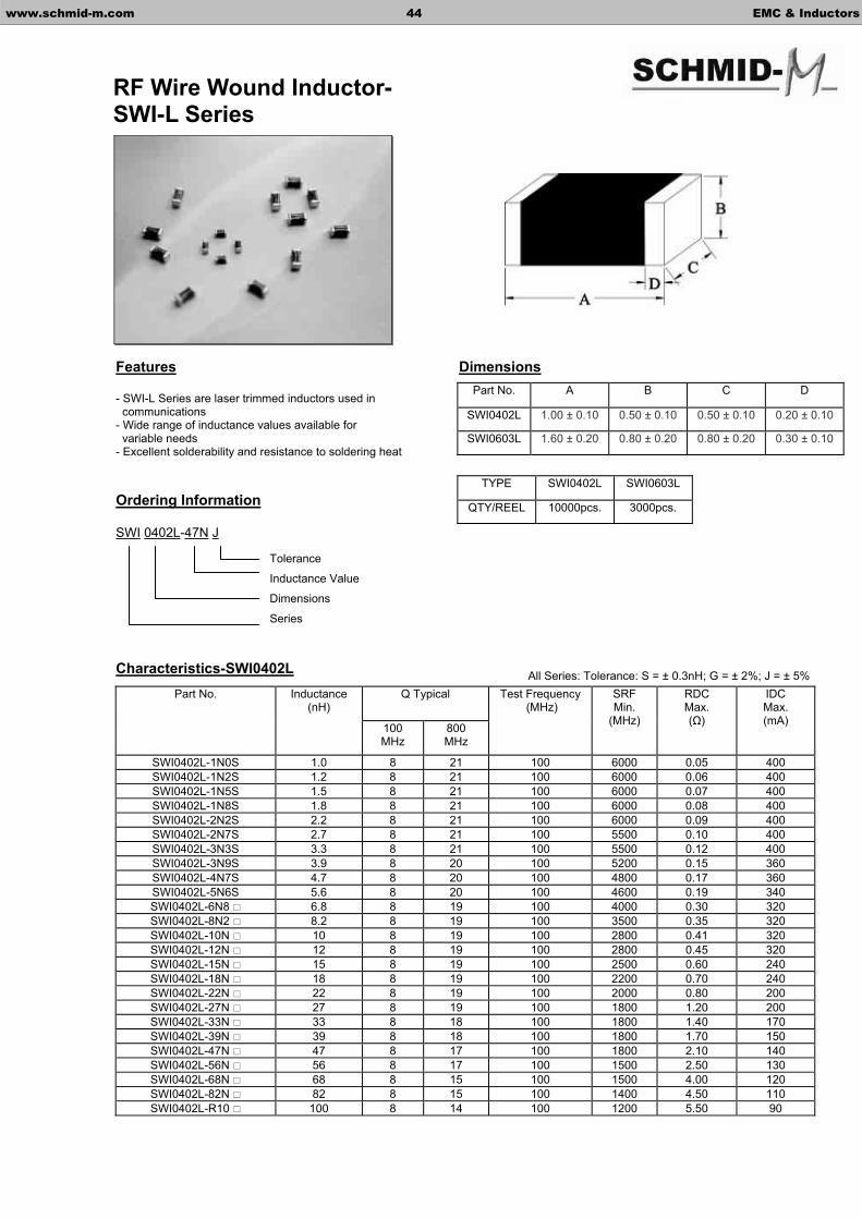
- SWI-L Series are laser trimmed inductors used in communications - Wide range of inductance values available for variable needs - Excellent solderability and resistance to soldering heat
Ordering Information
SWI 0402L-47N J
Characteristics-SWI0402L
Q Typical Part No. Inductance (nH)
100MHz
800MHz
Test Frequency (MHz)
SRFMin.
(MHz)
RDCMax. ( )
IDCMax. (mA)
SWI0402L-1N0S 1.0 8 21 100 6000 0.05 400 SWI0402L-1N2S 1.2 8 21 100 6000 0.06 400 SWI0402L-1N5S 1.5 8 21 100 6000 0.07 400 SWI0402L-1N8S 1.8 8 21 100 6000 0.08 400 SWI0402L-2N2S 2.2 8 21 100 6000 0.09 400 SWI0402L-2N7S 2.7 8 21 100 5500 0.10 400 SWI0402L-3N3S 3.3 8 21 100 5500 0.12 400 SWI0402L-3N9S 3.9 8 20 100 5200 0.15 360 SWI0402L-4N7S 4.7 8 20 100 4800 0.17 360 SWI0402L-5N6S 5.6 8 20 100 4600 0.19 340 SWI0402L-6N8 6.8 8 19 100 4000 0.30 320 SWI0402L-8N2 8.2 8 19 100 3500 0.35 320 SWI0402L-10N 10 8 19 100 2800 0.41 320 SWI0402L-12N 12 8 19 100 2800 0.45 320 SWI0402L-15N 15 8 19 100 2500 0.60 240 SWI0402L-18N 18 8 19 100 2200 0.70 240 SWI0402L-22N 22 8 19 100 2000 0.80 200 SWI0402L-27N 27 8 19 100 1800 1.20 200 SWI0402L-33N 33 8 18 100 1800 1.40 170 SWI0402L-39N 39 8 18 100 1800 1.70 150 SWI0402L-47N 47 8 17 100 1800 2.10 140 SWI0402L-56N 56 8 17 100 1500 2.50 130 SWI0402L-68N 68 8 15 100 1500 4.00 120 SWI0402L-82N 82 8 15 100 1400 4.50 110 SWI0402L-R10 100 8 14 100 1200 5.50 90
Tolerance
Inductance Value
Dimensions
Series
www.schmid-m.com 44 EMC & Inductors
RF Wire Wound Inductor- SWI-L Series
Part No. A B C D
SWI0402L 1.00 ± 0.10 0.50 ± 0.10 0.50 ± 0.10 0.20 ± 0.10
SWI0603L 1.60 ± 0.20 0.80 ± 0.20 0.80 ± 0.20 0.30 ± 0.10
TYPE SWI0402L SWI0603L
QTY/REEL 10000pcs. 3000pcs.
All Series: Tolerance: S = ± 0.3nH; G = ± 2%; J = ± 5%
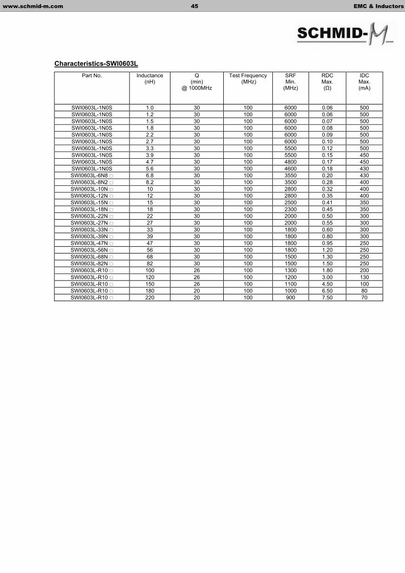
Characteristics-SWI0603LPart No. Inductance
(nH)Q
(min) @ 1000MHz
Test Frequency (MHz)
SRFMin.
(MHz)
RDCMax. ( )
IDCMax. (mA)
SWI0603L-1N0S 1.0 30 100 6000 0.06 500 SWI0603L-1N0S 1.2 30 100 6000 0.06 500 SWI0603L-1N0S 1.5 30 100 6000 0.07 500 SWI0603L-1N0S 1.8 30 100 6000 0.08 500 SWI0603L-1N0S 2.2 30 100 6000 0.09 500 SWI0603L-1N0S 2.7 30 100 6000 0.10 500 SWI0603L-1N0S 3.3 30 100 5500 0.12 500 SWI0603L-1N0S 3.9 30 100 5500 0.15 450 SWI0603L-1N0S 4.7 30 100 4800 0.17 450 SWI0603L-1N0S 5.6 30 100 4600 0.18 430 SWI0603L-6N8 6.8 30 100 3550 0.20 430 SWI0603L-8N2 8.2 30 100 3500 0.28 400 SWI0603L-10N 10 30 100 2800 0.32 400 SWI0603L-12N 12 30 100 2800 0.35 400 SWI0603L-15N 15 30 100 2500 0.41 350 SWI0603L-18N 18 30 100 2300 0.45 350 SWI0603L-22N 22 30 100 2000 0.50 300 SWI0603L-27N 27 30 100 2000 0.55 300 SWI0603L-33N 33 30 100 1800 0.60 300 SWI0603L-39N 39 30 100 1800 0.80 300 SWI0603L-47N 47 30 100 1800 0.95 250 SWI0603L-56N 56 30 100 1800 1.20 250 SWI0603L-68N 68 30 100 1500 1.30 250 SWI0603L-82N 82 30 100 1500 1.50 250 SWI0603L-R10 100 26 100 1300 1.80 200 SWI0603L-R10 120 26 100 1200 3.00 130 SWI0603L-R10 150 26 100 1100 4.50 100 SWI0603L-R10 180 20 100 1000 6.50 80 SWI0603L-R10 220 20 100 900 7.50 70
www.schmid-m.com 45 EMC & Inductors

Features Dimensions
- Designed for power supply with high reliability and saturation - High current rating for high current circuits - Designed by special lead wire to prevent open circuit failure
Ordering Information
SPK 0703-4R7 K
Characteristics
SPK0406 SPK0608 SPK0810 SPK0912 SPK1016 Code L (µH)
RDCMax. ( )
IDCMax. (A)
RDCMax. ( )
IDCMax. (A)
RDCMax. ( )
IDCMax. (A)
RDCMax. ( )
IDCMax. (A)
RDCMax. ( )
IDCMax. (A)
100 10 0.10 1.70 0.04 3.00 0.03 5.30 0.03 7.50 0.02 10.00120 12 0.14 1.50 0.05 3.00 0.04 4.70 0.03 7.20 0.02 9.50150 15 0.13 1.38 0.06 2.60 0.04 4.40 0.03 6.50 0.02 8.20180 18 0.15 1.27 0.07 2.40 0.05 3.90 0.04 5.60 0.02 7.60220 22 0.18 1.10 0.08 2.30 0.05 3.50 0.04 5.30 0.03 7.00270 27 0.20 1.05 0.09 2.10 0.06 3.30 0.05 4.70 0.05 6.00330 33 0.24 0.93 0.12 1.90 0.07 3.00 0.06 4.20 0.05 5.60390 39 0.31 0.85 0.17 1.70 0.07 2.70 0.08 3.90 0.06 5.00470 47 0.35 0.80 0.19 1.50 0.08 2.50 0.09 3.50 0.06 4.60560 56 0.42 0.72 0.20 1.40 0.11 2.30 0.09 3.20 0.07 4.20680 68 0.47 0.66 0.23 1.30 0.12 2.00 0.11 3.00 0.08 3.90820 82 0.55 0.60 0.33 1.15 0.16 1.80 0.14 2.70 0.09 3.60101 100 0.68 0.53 0.38 1.05 0.18 1.70 0.19 2.40 0.13 3.20121 120 0.91 0.51 0.38 0.95 0.25 1.55 0.21 2.20 0.15 2.90151 150 1.06 0.42 0.49 0.78 0.29 1.35 0.24 2.00 0.17 2.60181 180 1.31 0.41 0.76 0.77 0.34 1.23 0.27 1.80 0.19 2.40221 220 1.72 0.35 0.87 0.70 0.38 1.15 0.35 1.70 0.25 2.20271 270 2.07 0.32 0.98 0.65 0.48 1.00 0.48 1.50 0.34 1.90331 330 2.44 0.28 1.15 0.58 0.59 0.92 0.55 1.36 0.38 1.70391 390 2.65 0.26 1.27 0.52 0.77 0.84 0.60 1.26 0.41 1.60471 470 2.91 0.24 1.63 0.47 0.92 0.74 0.84 1.12 0.48 1.50561 560 3.27 0.23 2.44 0.44 1.02 0.72 0.93 1.00 0.65 1.35681 680 4.93 0.19 2.75 0.38 1.31 0.65 1.06 0.92 0.93 1.26821 820 5.53 0.18 3.09 0.36 1.46 0.58 1.31 0.85 1.04 1.15102 1000 7.60 0.17 3.49 0.33 1.73 0.53 1.49 0.78 1.06 1.00
ToleranceInductance Value Dimensions
B-Base; A-Axial; S-Salient, 3W-3 Lead Wires
Series
www.schmid-m.com 46 EMC & Inductors
Leaded Wire Wound Inductor – SPK Series
PartNo.
SPK0406 SPK0608 SPK0810 SPK0912 SPK1016
A 5.5 Max. 7.5 Max. 9.5 Max. 10.5 Max. 11.5 Max.
B 7.5 Max. 9.5 Max. 11.5 Max. 13.5 Max. 17.5 Max.
C 16.0 ± 3.0 16.0 ± 3.0 16.0 ± 3.0 16.0 ± 3.0 16.0 ± 3.0
D 0.50 ± 0.05 0.65 ± 0.05 0.65 ± 0.05 0.80 ± 0.05 0.80 ± 0.05
E 2.0 ± 0.05 3.0 ± 0.05 5.0 ± 0.05 6.0 ± 0.05 6.0 ± 0.05
F 3.0 Max. 3.0 Max. 3.0 Max. 3.0 Max. 3.0 Max.
TYPE SPK0406 SPK0608 SPK0810 SPK0912 SPK1016
PE Bag 500pcs. 500pcs. 250pcs. 250pcs. 250pcs.
Tolerance: K = ± 10%; K tolerance is Standard.

Features
- Unique configuration - Ideal for EMI countermeasures - Shapes and dimensions follow E.I.A. Spec. - Excellent soldering ability and heat resistance - High reliability
Ordering Information
SQT-02 251
Dimensions
Characteristics
Part No. A B C D E F G
SQT-02 8.0 Max. 9.5 Max. 3.5 Max. 4.5 ± 0.5 15.0 ± 0.10 19.0 ± 0.15 0.6 REF
Part No. Inductance (µH)
@1KHz/1.0V
Impedance( ) Min.
RatedVoltage
(V)
DCResistance(m ) Max.
IDC(A)
Test Frequency
(MHz) SQT-02251 4.7 250 50 20 0.20 100
SQT-02401 8.2 400 50 25 0.20 100
SQT-02501 33 500 50 35 0.50 100
SQT-02801 40 800 50 40 0.50 100
SQT-02122 60 1200 50 58 0.50 100
SQT-02152 80 1500 50 62 0.50 100
SQT-02172 100 1700 50 95 0.50 100
SQT-02202 120 2000 50 100 0.50 100
Impedance Value
Pins
Series
www.schmid-m.com 47 EMC & Inductors
Leaded Line Filter – SQT02 Series
B
D
EF G
A C
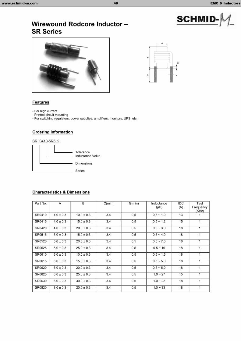
Features
- For high current - Printed circuit mounting - For switching regulators, power supplies, amplifiers, monitors, UPS, etc.
Ordering Information
SR 0410-5R6 K
Characteristics & Dimensions
Part No. A B C(min) G(min) Inductance (µH)
IDC(A)
Test Frequency
(KHz) SR0410 4.0 ± 0.3 10.0 ± 0.3 3.4 0.5 0.5 ~ 1.0 13 1
SR0415 4.0 ± 0.3 15.0 ± 0.3 3.4 0.5 0.5 ~ 1.2 15 1
SR0420 4.0 ± 0.3 20.0 ± 0.3 3.4 0.5 0.5 ~ 3.0 18 1
SR0515 5.0 ± 0.3 15.0 ± 0.3 3.4 0.5 0.5 ~ 4.0 18 1
SR0520 5.0 ± 0.3 20.0 ± 0.3 3.4 0.5 0.5 ~ 7.0 18 1
SR0525 5.0 ± 0.3 25.0 ± 0.3 3.4 0.5 0.5 ~ 10 18 1
SR0610 6.0 ± 0.3 10.0 ± 0.3 3.4 0.5 0.5 ~ 1.5 18 1
SR0615 6.0 ± 0.3 15.0 ± 0.3 3.4 0.5 0.5 ~ 5.0 18 1
SR0620 6.0 ± 0.3 20.0 ± 0.3 3.4 0.5 0.8 ~ 5.0 18 1
SR0625 6.0 ± 0.3 25.0 ± 0.3 3.4 0.5 1.0 ~ 27 15 1
SR0630 6.0 ± 0.3 30.0 ± 0.3 3.4 0.5 1.0 ~ 22 18 1
SR0820 8.0 ± 0.3 20.0 ± 0.3 3.4 0.5 1.0 ~ 33 18 1
ToleranceInductance Value
Dimensions
Series
www.schmid-m.com 48 EMC & Inductors
Wirewound Rodcore Inductor – SR Series
A
C
B
F
G
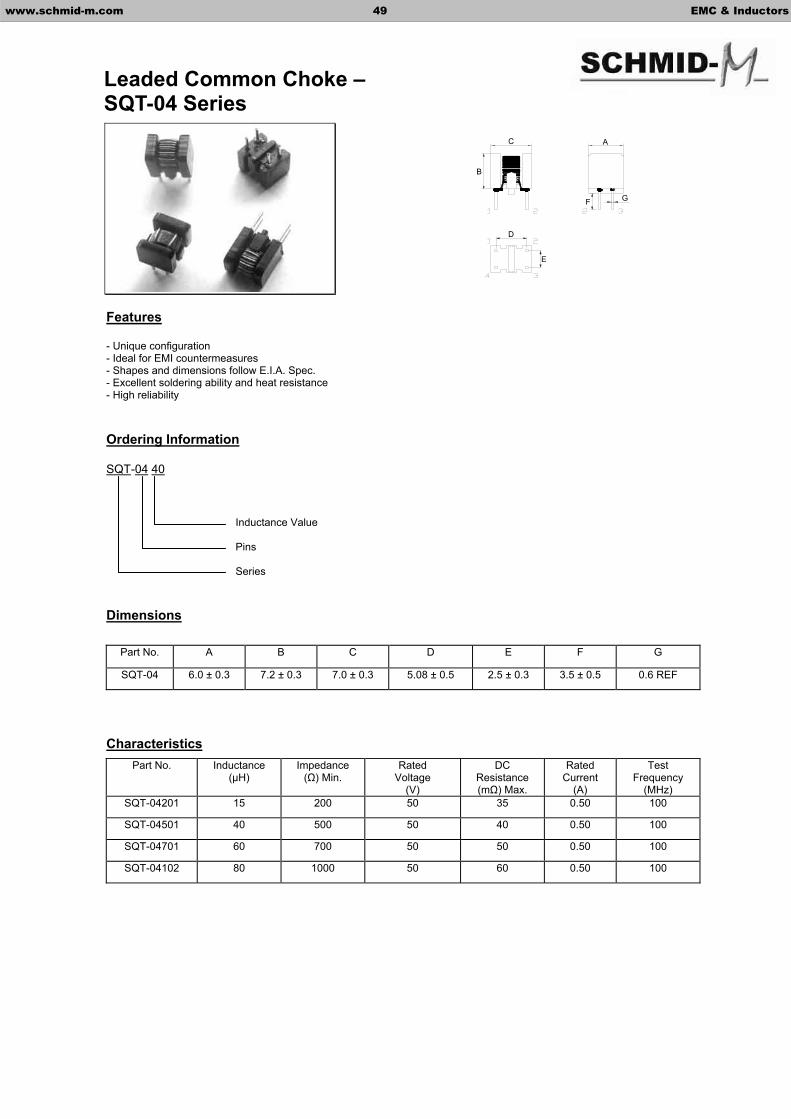
Features
- Unique configuration - Ideal for EMI countermeasures - Shapes and dimensions follow E.I.A. Spec. - Excellent soldering ability and heat resistance - High reliability
Ordering Information
SQT-04 40
Dimensions
Characteristics
Part No. A B C D E F G
SQT-04 6.0 ± 0.3 7.2 ± 0.3 7.0 ± 0.3 5.08 ± 0.5 2.5 ± 0.3 3.5 ± 0.5 0.6 REF
Part No. Inductance (µH)
Impedance( ) Min.
RatedVoltage
(V)
DCResistance(m ) Max.
RatedCurrent
(A)
Test Frequency
(MHz) SQT-04201 15 200 50 35 0.50 100
SQT-04501 40 500 50 40 0.50 100
SQT-04701 60 700 50 50 0.50 100
SQT-04102 80 1000 50 60 0.50 100
Inductance Value
Pins
Series
www.schmid-m.com 49 EMC & Inductors
Leaded Common Choke –SQT-04 Series
G
A
B
D
E
F
C
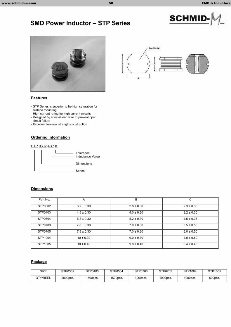
Features
- STP Series is superior to be high saturation for surface mounting - High current rating for high current circuits - Designed by special lead wire to prevent open circuit failure - Excellent terminal strength construction
Ordering Information
STP 0302-4R7 K
Dimensions
Package
SIZE STP0302 STP0403 STP0504 STP0703 STP0705 STP1004 STP1005
QTY/REEL 2000pcs. 1500pcs. 1500pcs. 1000pcs. 1000pcs. 1000pcs. 500pcs.
Part No. A B C
STP0302 3.2 ± 0.30 2.8 ± 0.30 2.3 ± 0.30
STP0403 4.5 ± 0.30 4.0 ± 0.30 3.2 ± 0.30
STP0504 5.8 ± 0.30 5.2 ± 0.30 4.5 ± 0.35
STP0703 7.8 ± 0.30 7.0 ± 0.30 3.5 ± 0.50
STP0705 7.8 ± 0.30 7.0 ± 0.30 5.0 ± 0.50
STP1004 10 ± 0.30 9.0 ± 0.30 4.0 ± 0.50
STP1005 10 ± 0.40 9.0 ± 0.40 5.4 ± 0.40
ToleranceInductance Value
Dimensions
Series
www.schmid-m.com 50 EMC & Inductors
SMD Power Inductor – STP Series
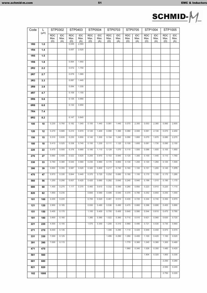
STP0302 STP0403 STP0504 STP0703 STP0705 STP1004 STP1005 Code L (µH)
RDCMax. ( )
IDC Max. (A)
RDCMax. ( )
IDC Max. (A)
RDCMax. ( )
IDC Max. (A)
RDCMax. ( )
IDC Max. (A)
RDCMax. ( )
IDC Max. (A)
RDCMax. ( )
IDC Max. (A)
RDCMax. ( )
IDC Max. (A)
1R0 1.0 0.049 2.560
1R4 1.4 0.057 2.520
1R5 1.5
1R8 1.8 0.064 1.950
2R2 2.2 0.072 1.750
2R7 2.7 0.079 1.580
3R3 3.3 0.087 1.440
3R9 3.9 0.094 1.330
4R7 4.7 0.109 1.150
5R6 5.6 0.126 0.990
6R8 6.8 0.132 0.950
7R4 7.4
8R2 8.2 0.147 0.840
100 10 0.230 0.760 0.182 1.040 0.100 1.440 0.081 1.440 0.070 2.300 0.053 2.380 0.060 2.600
120 12 0.270 0.685 0.210 0.970 0.120 1.400 0.090 1.390 0.080 2.000 0.061 2.130 0.070 2.450
150 15 0.310 0.635 0.235 0.850 0.140 1.300 0.104 1.240 0.090 1.800 0.070 1.870 0.080 2.270
180 18 0.410 0.525 0.338 0.740 0.150 1.230 0.111 1.120 0.100 1.600 0.081 1.730 0.090 2.150
220 22 0.470 0.500 0.378 0.680 0.180 1.110 0.129 1.070 0.110 1.500 0.088 1.600 0.100 1.950
270 27 0.660 0.405 0.522 0.620 0.200 0.970 0.153 0.940 0.120 1.300 0.100 1.440 0.110 1.760
330 33 0.760 0.380 0.540 0.560 0.230 0.880 0.170 0.850 0.130 1.200 0.120 1.260 0.120 1.500
390 39 0.850 0.355 0.587 0.520 0.320 0.800 0.217 0.740 0.160 1.100 0.151 1.200 0.140 1.370
470 47 0.970 0.330 0.844 0.440 0.370 0.720 0.252 0.680 0.180 1.100 0.170 1.100 0.170 1.280
560 56 1.250 0.290 0.937 0.420 0.420 0.680 0.282 0.640 0.240 0.940 0.199 1.010 0.190 1.170
680 68 1.450 0.275 1.117 0.370 0.460 0.610 0.332 0.590 0.280 0.850 0.223 0.910 0.220 1.110
820 82 1.850 0.235 0.600 0.580 0.406 0.540 0.370 0.780 0.252 0.850 0.250 1.000
101 100 2.200 0.220 0.700 0.520 0.481 0.510 0.430 0.720 0.344 0.740 0.350 0.970
121 120 2.900 0.185 0.930 0.480 0.536 0.490 0.470 0.660 0.396 0.690 0.400 0.890
151 150 3.400 0.170 1.100 0.400 0.755 0.400 0.640 0.580 0.544 0.610 0.470 0.780
181 180 3.900 0.165 1.380 0.380 1.022 0.360 0.710 0.510 0.621 0.560 0.630 0.720
221 220 4.500 0.155 1.570 0.350 1.200 0.310 0.960 0.490 0.721 0.530 0.730 0.660
271 270 6.000 0.135 1.306 0.290 1.110 0.420 0.949 0.450 0.970 0.570
331 330 7.000 0.125 1.495 0.280 1.260 0.400 1.100 0.420 1.150 0.520
391 390 7.000 0.115 1.770 0.360 1.245 0.380 1.300 0.480
471 470 1.960 0.340 1.526 0.350 1.480 0.420
561 560 1.904 0.320 1.900 0.330
681 680 2.250 0.280
821 820 2.550 0.240
102 1000 2.750 0.220
www.schmid-m.com 51 EMC & Inductors

Features Dimensions
- Thinnest power coil - Ceramic cover provides best possible surface for pick and place handling - Perfect for small cards
Ordering Information
SCMD 0401-4R7 M
Characteristics
Part No. L (µH)
Test Frequency (KHz)
RDCMax. ( )
IDCMax. (A)
SCMD0401-2R2M 2.2 100 0.116 0.95
SCMD0401-3R3M 3.3 100 0.174 0.77
SCMD0401-4R7M 4.7 100 0.216 0.75
SCMD0401-6R8M 6.8 100 0.296 0.62
SCMD0401-100M 10 100 0.457 0.50
SCMD0401-150M 15 100 0.676 0.40
SCMD0401-220M 22 100 1.066 0.30
SCMD0401-330M 33 100 1.647 0.24
SCMD0401-470M 47 100 2.843 0.18
Tolerance
Inductance Value
Dimensions
Series
www.schmid-m.com 52 EMC & Inductors
SMD Power Inductor – SCMD Series
Part No. A B C
SCMD0401 4.4 Max. 5.8 Max. 1.2 Max.
QTY/REEL 5000pcs.
Tolerance: M = ± 20%, M tolerance is standard.

Features Dimensions
- SSPK Series are designed for the smallest possible size and high performance,high storage and very low resistance - Very small footprint - Increased size selection guide - Designed by special lead wire to prevent open circuit failure
Ordering Information
SSPK 0802 100 M
Characteristics
SSPK0802 SSPK0804 SSPK0810 SSPK1306 Code L (µH)
RDCMax. ( )
IDCMax. (A)
RDCMax. ( )
IDCMax. (A)
RDCMax. ( )
IDCMax. (A)
RDCMax. ( )
IDCMax. (A)
3R3 3.3 0.015 6.40
4R7 4.7 0.018 5.40
6R8 6.8 0.027 4.60
100 10 0.110 2.40 0.038 3.80 0.040 8.00 0.031 10.00
150 15 0.150 2.00 0.046 3.00 0.050 7.00 0.036 8.00
220 22 0.230 1.60 0.085 2.60 0.066 5.50 0.047 7.00
330 33 0.300 1.40 0.100 2.00 0.080 4.00 0.066 5.50
470 47 0.390 1.00 0.140 1.60 0.110 3.80 0.086 4.50
680 68 0.660 0.90 0.200 1.40 0.170 3.00 0.130 3.50
101 100 0.840 0.70 0.280 1.20 0.220 2.50 0.190 3.00
151 150 0.400 1.00 0.340 2.00 0.250 2.60
221 220 0.610 0.80 0.440 1.60 0.380 2.40
331 330 1.020 0.60 0.700 1.20 0.560 1.90
471 470 1.270 0.50 0.950 1.00 0.850 1.40
681 680 1.200 1.00 1.100 1.20
102 1000 2.000 0.80 1.800 1.00
Tolerance
Inductance Value Dimensions
Series
www.schmid-m.com 53 EMC & Inductors
SMD Power Inductor – SSPK Series
Part No. A B C D
SSPK0802 8.6 Max. 3.0 Max. 9.5 Max. 13.5 Max.
SSPK0804 8.6 Max. 5.5 Max. 9.5 Max. 13.5 Max.
SSPK0810 8.6 Max. 11.5 Max. 9.5 Max. 13.5 Max.
SSPK1306 13.0 Max. 7.5 Max. 15.4 Max. 18.54 Max.
SSPK0802 SSPK0804 SSPK0810 SSPK1306
1000pcs. 1000pcs. 250pcs. 250pcs.
Test Frequency 100KHz
Tolerance: M = ± 20%; N = ± 25%, M tolerance is standard.

Features Dimensions
- For high current, low voltage DC/DC Converters - Microprocessors (esp. the latest generation of 3.3V products) - High current rating, low DC resistance - Reliable surface mounting with a large flat top and self-leaded design
Ordering Information
SSPH 0504-4R7 M
Characteristics
Part No. L (µH)
Test Frequency (KHz)
RDCMax.( )
IDCMax.(A)
SSPH0504-R56M 0.56 100 0.010 7.70 SSPH0504-1R2M 1.20 100 0.017 5.30 SSPH0504-2R2M 2.20 100 0.035 3.50 SSPH0504-4R7M 4.70 100 0.054 2.60 SSPH0504-100M 10.0 100 0.111 1.90 SSPH0504-150M 15.0 100 0.170 1.50 SSPH0504-220M 22.0 100 0.250 1.20 SSPH0504-330M 33.0 100 0.350 0.99 SSPH0504-470M 47.0 100 0.470 0.87 SSPH0804-R33M 0.33 100 0.002 20.0 SSPH0804-R68M 0.68 100 0.005 13.0 SSPH0804-1R0M 1.00 100 0.006 11.0 SSPH0804-1R5M 1.50 100 0.008 9.00 SSPH0804-2R2M 2.20 100 0.011 7.80 SSPH0804-2R7M 2.70 100 0.012 7.00 SSPH0804-3R3M 3.30 100 0.014 6.40 SSPH0804-4R7M 4.70 100 0.018 5.40 SSPH1306-R78M 0.78 100 0.0026 30.0 SSPH1306-1R5M 1.50 100 0.004 25.0 SSPH1306-2R2M 2.20 100 0.0061 20.0 SSPH1306-3R3M 3.30 100 0.0086 17.0 SSPH1306-3R9M 3.90 100 0.010 15.0 SSPH1306-4R7M 4.70 100 0.014 13.0 SSPH1306-6R0M 6.00 100 0.017 12.0 SSPH1306-7R8M 7.80 100 0.018 11.0 SSPH1306-100M 10.0 100 0.026 10.0 SSPH1306-150M 15.0 100 0.032 8.00
Tolerance
Inductance Value DimensionsSeries
www.schmid-m.com 54 EMC & Inductors
SMD Power Inductor – SSPH Series
Part No. A B C D
SSPH0504 4.8 ± 0.15 5.00 Max. 6.10 Max. 8.89 Max.
SSPH0804 8.6 Max. 6.35 Max. 9.91 Max. 13.21 Max.
SSPH1306 13.0 Max. 8.00 Max. 16.26 Max. 22.35 Max.
TYPE SSPH0504 SSPH0804 SSPH1306
QTY/REEL 1000pcs. 750pcs. 250pcs.
Tolerance: M = ± 20%, M tolerance is standard.
Features Dimensions
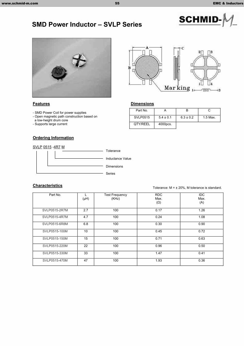
- SMD Power Coil for power supplies - Open magnetic path construction based on a low-height drum core - Supports large current
Ordering Information
SVLP 0515 -4R7 M
Characteristics
Part No. L (µH)
Test Frequency (KHz)
RDCMax. ( )
IDCMax. (A)
SVLP0515-2R7M 2.7 100 0.17 1.26
SVLP0515-4R7M 4.7 100 0.24 1.08
SVLP0515-6R8M 6.8 100 0.30 0.90
SVLP0515-100M 10 100 0.45 0.72
SVLP0515-150M 15 100 0.71 0.63
SVLP0515-220M 22 100 0.96 0.50
SVLP0515-330M 33 100 1.47 0.41
SVLP0515-470M 47 100 1.93 0.36
Tolerance
Inductance Value
Dimensions
Series
www.schmid-m.com 55 EMC & Inductors
SMD Power Inductor – SVLP Series
Part No. A B C
SVLP0515 5.4 ± 0.1 6.3 ± 0.2 1.5 Max.
QTY/REEL 4000pcs.
Tolerance: M = ± 20%, M tolerance is standard.
Features
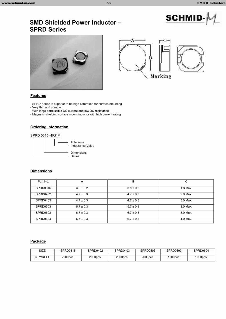
- SPRD Series is superior to be high saturation for surface mounting - Very thin and compact - With large permissible DC current and low DC resistance - Magnetic shielding surface mount inductor with high current rating
Ordering Information
SPRD 0315–4R7 M
Dimensions
Package
SIZE SPRD0315 SPRD0402 SPRD0403 SPRD0503 SPRD0603 SPRD0604
QTY/REEL 2000pcs. 2000pcs. 2000pcs. 2000pcs. 1000pcs. 1000pcs.
Part No. A B C
SPRD0315 3.8 ± 0.2 3.8 ± 0.2 1.8 Max.
SPRD0402 4.7 ± 0.3 4.7 ± 0.3 2.0 Max.
SPRD0403 4.7 ± 0.3 4.7 ± 0.3 3.0 Max.
SPRD0503 5.7 ± 0.3 5.7 ± 0.3 3.0 Max.
SPRD0603 6.7 ± 0.3 6.7 ± 0.3 3.0 Max.
SPRD0604 6.7 ± 0.3 6.7 ± 0.3 4.0 Max.
ToleranceInductance Value
DimensionsSeries
www.schmid-m.com 56 EMC & Inductors
SMD Shielded Power Inductor –SPRD Series

SPRD0315 SPRD0402 SPRD0403 SPRD0503 SPRD0603 SPRD0604 Code L (µH)
RDCMax. ( )
IDCMax. (A)
RDCMax. ( )
IDCMax. (A)
RDCMax. ( )
IDCMax. (A)
RDCMax. ( )
IDCMax. (A)
RDCMax. ( )
IDCMax. (A)
RDCMax. ( )
IDCMax. (A)
1R0 1.0 0.045 1.72
1R2 1.2 0.024 2.56
1R8 1.8 0.028 2.20
2R2 2.2 0.075 1.32 0.032 2.04
2R5 2.5 0.018 2.60
2R7 2.7 0.105 1.28 0.044 1.60
3R0 3.0 0.024 2.40 0.024 3.00
3R3 3.3 0.066 0.80 0.110 1.04 0.050 1.57 0.020 3.50
3R9 3.9 0.081 0.75 0.155 0.88 0.065 1.44 0.027 2.60
4R2 4.2 0.031 2.20
4R7 4.7 0.091 0.68 0.162 0.84 0.072 1.32
5R0 5.0 0.031 2.40 0.024 2.90
5R3 5.3 0.038 1.90
5R6 5.6 0.102 0.62 0.170 0.80 0.101 1.17
6R0 6.0 0.035 2.25
6R2 6.2 0.045 1.80 0.027 2.50
6R8 6.8 0.130 0.58 0.200 0.76 0.109 1.12
7R3 7.3 0.054 2.10
7R4 7.4 0.031 2.30
8R2 8.2 0.140 0.51 0.245 0.68 0.118 1.04 0.053 1.60
8R6 8.6 0.058 1.85
8R7 8.7 0.034 2.20
100 10 0.190 0.46 0.200 0.61 0.129 1.00 0.065 1.30 0.065 1.70 0.038 2.00
120 12 0.205 0.42 0.210 0.56 0.132 0.84 0.076 1.20 0.070 1.55 0.053 1.70
150 15 0.272 0.38 0.240 0.50 0.149 0.76 0.103 1.10 0.084 1.40 0.057 1.60
180 18 0.327 0.34 0.338 0.48 0.166 0.72 0.110 1.00 0.095 1.32 0.092 1.50
220 22 0.356 0.31 0.397 0.41 0.235 0.70 0.122 0.90 0.128 1.20 0.096 1.30
270 27 0.470 0.28 0.441 0.35 0.261 0.58 0.175 0.85 0.142 1.05 0.109 1.20
330 33 0.560 0.26 0.694 0.32 0.378 0.56 0.189 0.75 0.165 0.97 0.124 1.10
390 39 0.700 0.24 0.709 0.30 0.384 0.50 0.212 0.70 0.210 0.86 0.138 1.00
470 47 0.775 0.21 0.587 0.48 0.260 0.62 0.238 0.80 0.155 0.95
560 56 0.625 0.41 0.305 0.58 0.277 0.73 0.202 0.85
680 68 0.699 0.35 0.355 0.52 0.304 0.65 0.234 0.75
820 82 0.915 0.32 0.463 0.46 0.390 0.60 0.324 0.70
101 100 1.020 0.29 0.520 0.42 0.535 0.54 0.358 0.65
121 120 1.270 0.27
151 150 1.350 0.24
181 180 1.540 0.22
www.schmid-m.com 57 EMC & Inductors
SMD Shielded Power Inductor –SPRD Series
Tolerance: M = ± 20%, M tolerance is standard.

Features Dimensions
- SPRH series is superior to be high saturation for surface mounting - Magnetic shielding - Very small footprint - Flat-top for pick and place - Increased size selection-guide - Low resistance to keep power loss minimum
Ordering Information
SPRH 0703 – 5R8 M
Characteristics
SPRH0703 SPRH0704 SPRH1205 SPRH1207 Code L (µH) RDC
Max.( )IDC
Max.(A) RDC
Max.( )IDC
Max.(A) RDC
Max.( )IDC
Max.(A) RDC
Max.( )IDC
Max.(A) 1R0 1.0 0.007 14.001R3 1.3 0.012 8.00 2R1 2.1 0.014 7.00 2R4 2.4 0.011 10.303R1 3.1 0.017 6.00 3R5 3.5 0.013 9.304R4 4.4 0.020 5.00 4R6 4.6 0.014 9.105R8 5.8 0.021 4.40 0.017 8.607R4 7.4 0.018 7.407R5 7.5 0.024 4.20 100 10 0.072 1.68 0.049 1.84 0.025 4.00 0.020 6.70120 12 0.098 1.52 0.058 1.71 0.027 3.50 0.022 6.45150 15 0.130 1.33 0.081 1.47 0.030 3.30 0.027 5.65180 18 0.140 1.20 0.091 1.31 0.034 3.00 0.028 5.10220 22 0.190 1.07 0.110 1.23 0.036 2.80 0.037 4.70270 27 0.210 0.96 0.150 1.12 0.051 2.30 0.042 4.20330 33 0.240 0.91 0.170 0.96 0.057 2.10 0.054 3.90390 39 0.320 0.77 0.230 0.91 0.068 2.00 0.061 3.50470 47 0.360 0.76 0.260 0.88 0.075 1.80 0.078 3.25560 56 0.470 0.68 0.350 0.75 0.110 1.70 0.090 2.90680 68 0.520 0.61 0.380 0.69 0.120 1.50 0.120 2.60820 82 0.690 0.57 0.430 0.61 0.140 1.40 0.119 2.40101 100 0.790 0.50 0.610 0.60 0.160 1.30 0.151 2.10121 120 0.890 0.49 0.660 0.52 0.170 1.10 0.169 1.90151 150 1.270 0.43 0.880 0.46 0.230 1.00 0.227 1.80181 180 1.450 0.39 0.980 0.42 0.290 0.90 0.299 1.55221 220 1.650 0.35 1.170 0.36 0.400 0.80 0.338 1.45271 270 2.310 0.32 1.640 0.34 0.460 0.75 0.419 1.30331 330 2.620 0.28 1.860 0.32 0.510 0.68 0.471 1.20391 390 2.940 0.26 2.850 0.29 0.690 0.65 0.572 1.10471 470 4.180 0.24 3.010 0.26 0.770 0.58 0.741 1.00561 560 4.670 0.22 3.620 0.23 0.860 0.54 0.852 0.95681 680 5.730 0.19 4.630 0.22 1.200 0.48 1.130 0.85821 820 6.540 0.18 5.200 0.20 1.340 0.43 1.240 0.75102 1000 9.440 0.16 6.000 0.18 1.530 0.40 1.500 0.70
Tolerance
Inductance Value
Dimensions
Series
www.schmid-m.com 58 EMC & Inductors
SMD Shielded Power Inductor –SPRH Series
Part No. A B C
SPRH0703 7.3 ± 0.2 7.3 ± 0.2 3.2 ± 0.2
SPRH0704 7.3 ± 0.2 7.3 ± 0.2 4.5 Max.
SPRH1205 12.0 ± 0.3 12.0 ± 0.3 6.0 Max.
SPRH1207 12.0 ± 0.3 12.0 ± 0.3 8.0 Max.
SIZE SPRH0703 SPRH0704 SPRH1205 SPRH1207
QTY/REEL 1000pcs. 1000pcs. 500pcs. 500pcs.
Tolerance: M = ± 20%, M tolerance is standard.

Features Dimensions- Magnetic shielding- Flat bottom surface ensures secure and reliable mounting - Low DC resistance, low profile and high current rating capacities
Ordering Information
SSB 0703–4R7 M
Characteristics
SSB0703 SSB0705 SSB1003 SSB1206 SSB1207 Code L (µH) RDC
Max.( )IDC
Max.(A) RDC
Max.( )IDC
Max.(A) RDC
Max.( )IDC
Max.(A) RDC
Max.( )IDC
Max.(A) RDC
Max.( )IDC
Max.(A)
1R0 1.0 0.019 3.12 0.020 2.80 1R5 1.5 0.023 2.85 0.024 2.59 2R0 2.0 0.014 6.202R2 2.2 0.028 2.66 0.028 2.38 0.016 5.00 3R3 3.3 0.035 2.26 0.034 2.14 4R0 4.0 0.023 3.20 4R2 4.2 0.018 5.504R7 4.7 0.043 1.96 0.039 1.96 6R0 6.0 0.020 4.90 6R8 6.8 0.055 1.76 0.050 1.79 7R0 7.0 0.042 2.30 0.022 5.00100 10 0.080 1.34 0.055 1.63 0.058 2.10 0.026 4.30 0.025 4.80120 12 0.090 1.23 0.073 1.42 150 15 0.120 1.09 0.081 1.33 0.080 1.60 0.032 3.90 0.029 4.40180 18 0.130 0.99 0.102 1.15 220 22 0.150 0.90 0.115 1.09 0.109 1.30 0.041 3.40 0.038 3.80270 27 0.210 0.81 0.159 0.91 330 33 0.250 0.72 0.182 0.84 0.177 1.10 0.050 3.10 0.049 3.40390 39 0.310 0.67 0.199 0.80 470 47 0.350 0.60 0.221 0.75 0.234 1.00 0.075 2.50 0.070 2.80560 56 0.430 0.55 0.306 0.64 680 68 0.520 0.50 0.345 0.60 0.324 0.90 0.101 2.20 0.095 2.40820 82 0.600 0.46 0.390 0.57 101 100 0.792 0.41 0.432 0.50 0.519 0.72 0.141 1.80 0.148 1.90121 120 0.440 0.47 151 150 0.730 0.40 0.228 1.40 181 180 0.780 0.39 221 220 0.940 0.33 1.215 0.46 0.624 1.20 0.328 1.20271 270 1.250 0.31 331 330 1.400 0.27 0.492 1.00 471 470 1.700 0.25 0.624 0.88 561 560 2.390 0.22 681 680 0.912 0.73 102 1000 1.344 0.60 152 1500 2.076 0.48
ToleranceInductance Value
DimensionsSeries
www.schmid-m.com 59 EMC & Inductors
SMD Shielded Power Inductor –SSB Series
Part No. A B C
SSB0703 7.6 Max. 7.6 Max. 3.5 Max.
SSB0705 7.6 Max. 7.6 Max. 5.1 Max.
SSB1003 10.5 Max. 10.5 Max. 3.5 Max.
SSB1206 12.5 ± 0.3 12.5 ± 0.3 5.5 ± 0.35
SSB1207 12.5 ± 0.3 12.5 ± 0.3 6.5 ± 0.35
SIZE SSB0703 SSB0705 SSB1003 SSB1206 SSB1207
QTY/REEL 1000pcs. 1000pcs. 1000pcs. 500pcs. 500pcs.
Tolerance: M = ± 20%, M tolerance is standard.

Features Dimensions
- Magnetic shielding - Flat bottom surface ensures secure and reliable mounting - Low DC resistance, low profile and high current rating capacities
Ordering Information
SSPS 0804–100 M
Characteristics
SSPS0804 SSPS1306 Code L (µH)
RDCMax. ( )
IDCMax. (A)
RDCMax. ( )
IDCMax. (A)
1R0 1.0 0.021 5.60 1R5 1.5 0.022 5.20 2R2 2.2 0.032 5.00 3R3 3.3 0.039 3.90 4R7 4.7 0.054 3.20 6R8 6.8 0.075 2.80 100 10 0.101 2.40 0.040 8.00150 15 0.150 2.00 0.048 7.00220 22 0.207 1.60 0.059 6.00330 33 0.334 1.40 0.075 5.00470 47 0.472 1.00 0.097 4.00680 68 0.138 3.00101 100 0.207 2.40151 150 0.293 2.10221 220 0.470 1.90331 330 0.780 1.10471 470 1.080 1.10681 680 1.400 0.96102 1000 2.010 0.80
ToleranceInductance Value
Dimensions
Series
www.schmid-m.com 60 EMC & Inductors
SMD Shielded Power Inductor –SSPS Series
Part No. A B C D
SSPS0804 8.40 ± 0.20 5.08 Max. 9.40 Max. 12.95 Max.
SSPS1306 12.70 ± 0.20 7.62 Max. 15.24 Max. 18.54 Max.
SSPS0804 SSPS1306
1000pcs. 250pcs.
Test Frequency 100KHz
Tolerance: M = ± 20%, M tolerance is standard.

Features
- Coated with varnish - High saturation current - Excellent high current rating
Ordering Information
STI 5026 101 M
Characteristic
STI4426 STI5026 STI6026 STI6826 PartCode
L(µH) RDC
( )IDC(A)
RDC( )
IDC(A)
RDC( )
IDC(A)
RDC( )
IDC(A)
220 22 0.04 2.50 0.03 3.50 0.02 4.50 0.01 5.00
330 33 0.09 2.00 0.04 2.60 0.03 4.00 0.03 4.10
470 47 0.10 1.80 0.04 2.20 0.05 3.20 0.04 3.60
680 68 0.16 1.40 0.05 1.90 0.06 2.50 0.06 2.80
820 82 0.14 1.30 0.06 1.80 0.10 2.40 0.07 2.40
101 100 0.15 1.30 0.07 1.50 0.11 2.20 0.06 2.00
121 120 0.16 1.10 0.09 1.40 0.15 2.00 0.07 2.00
151 150 0.20 0.95 0.12 1.20 0.10 1.60 0.07 1.60
221 220 0.30 0.90 0.21 0.90 0.12 1.40 0.12 1.40
331 330 0.45 0.70 0.30 0.84 0.21 1.00 0.21 1.20
471 470 0.83 0.60 0.47 0.70 0.33 0.95 0.32 1.00
Tolerance
Inductance Value
Dimensions
B-Base; W-White Bobbin; D-Double Wire, H-Horizontal
Series
www.schmid-m.com 61 EMC & Inductors
Toroidal Line Choke – STI Series
