characteristics of nano-reactor and phenomena during
TRANSCRIPT

1. Introduction
Many applications of the mechanical milling (mechani-cal alloying, ball milling or grinding) on the chemical reac-tion system (so called mechanochemistry), which related tocarbonaceous material, have been reported.1–21) At the sametime, the mechanochemistry of hematite (iron oxides) wereinvestigated extensively.22–30) On the other hand, the car-bothermic reaction between hematite (iron oxides) and car-bon was the subject of the iron making field for a longtime.31–36)
In previous study,37) the authors have investigated the re-activity of hematite–graphite mixture obtained by the me-chanical milling. The rate of reaction has remarkably in-creased and the starting temperature of reaction decreasedin accordance with the milling time.
A number of the affecting factors on the reactivity of themixture will exist. Furthermore, as the factors might inter-act each other, the apparent result would be complicate ex-tremely. For example, since the grindability of the samplewill strongly affect the properties of sample powder aftermilling, the property of crystal such as the size, the distri-bution and the hardness, which related to the nature of asingle crystal itself and a polycrystalline particle, would re-sult in the variety of the reactivity after milling.
To understand the reaction behavior obtained from me-chanical milling, it would be very important to clarify thephenomena occurring in the course of milling. It could easilyimagine the importance of the impact energy and the fre-
quency, so that the rotation speed, the weight of ball and thenumber of ball were all important factors to be control themilling effect. In addition to these factors, the quality of ma-terial and the surface structure (roughness) of ball and vesselfor milling were also unignorable factors. In the series ofpresent study, the effect of these factors are investigatingsystematically and the results will be reported in near future.
In this study, the phenomena occurring in the course ofmilling such as the gas evolution, reduction reaction andphase transformation (formation of active complex) wereinvestigated.
2. Experimental
Figure 1 shows the preparing procedure of hematite andgraphite samples. Reagent hematite (�99.0% Fe2O3) wascompressed into the tablet with 25 mmf�5 mm thickness.The tablet was sintered at 1 000°C for 24 h in air atmo-sphere. Then the sintered tablet was crushed roughly andadjusted the particle size distribution from 500 to 75 mmusing sieve before mechanical milling start. The graphitewas high density (1.77 g/cm3) and high purity (�100 ppmash content). The particle size was also adjusted with thesame range as the hematite. The detail of milling conditionwas the same as the previous study.37) The ratio of carbon tohematite was constant (C/O�1.1), which was the19.84wt%C–80.16wt%Fe2O3. This ratio means the 5% ex-cess carbon for the reduction by solid carbon, when the fol-lowing reaction proceeds completely.
ISIJ International, Vol. 44 (2004), No. 12, pp. 1975–1980
1975 © 2004 ISIJ
Characteristics of Nano-reactor and Phenomena during Mechanical Milling of Hematite–Graphite Mixture
Yoshiaki KASHIWAYA, Hiroshi SUZUKI1) and Kuniyoshi ISHII
Graduate School of Engineering, Hokkaido University, Sapporo 060–8628 Japan. E-mail: [email protected]) Student of Graduate School of Engineering, Hokkaido University, Sapporo 060–8628 Japan.
(Received on May 24, 2004; accepted in final form on July 26, 2004 )
The mechanical milling of hematite and graphite mixture could accelerate the reaction rate extremely,when the mixture after milling was heated up under inert atmosphere. In the previous study, the authorshave indicated not only the high reaction rate but also the low starting temperature of the reaction. Thesephenomena can be understood through the view point of the nano-reactor and the active complex. Thenano-reactor was defined in this study through the observation of the milling products by TEM and FE-SEM.The important characteristic of nano-reactor was proposed.
Moreover, the phenomena such as the reduction reaction, the phase transformation(formation of an ac-tive complex) and the crystalline size degradation occurring in the course of the milling were examined. Itwas found that the milling of mixture gave a different phenomenon from the single hematite or graphitemilling. Furthermore, the atmosphere during the milling affected on the reactivity of the milling product. Theexistence of oxygen caused the reoxidation of the reduction product which resulted in the different crys-talline size after milling.
KEY WORDS: nano-reactor; hematite; graphite; composite pellet; mechanical milling; ball milling; reduction;carbothermic reduction.

Fe2O3�3C�2Fe�3CO ........................(1)
The mixture was milled in the alumina vessel (500 cc)with ten alumina balls (weight was 17–24 g and diameterwas 20–23 mmf , which had relatively large tolerance andgradually decreased with milling time). The quality of alu-mina was a dense (3.9 g/cm3) and high purity Al2O3
(�99.6%).Figure 2 shows the SEM image of the different kind of
reagent hematite samples. The Special grade hematite wasused in the present experiment. The special grade reagenthematite shows the polycrystalline particle (from 1 to20 mm) consisting of smaller crystalline from 0.1 to 0.2 mm.On the other hand, 1st Grade hematite seems to be quitefine particle around 0.2 mm and agglomerates into a largerunit around 10 to 100 mm. The sintering effect on the crys-tal morphology was also different from the property of
starting hematite nature. The lower pictures in Fig. 2 showthe morphology of hematite after 24 h sintering at 1 000°C.It was found that the special grade hematite showed the ten-dency of the hard growing crystal. As mentioned above, theproperties of iron oxide affected the grindability of a pow-der, that resulted in the different kind of reactivity of pow-der.
Figure 3 shows the schematics of alumina vessels. Asthe teflon packing is a lower gas tight one, the silicone rub-ber packing was developed for atmosphere controlled ves-sel in this experiment. Figure 4 shows the gas analyzingsystem for the residual gas in the vessel after the milling.Before experiment, the atmosphere controlled vessel wasset in the system, and evacuated the gas remained both inthe vessel and in the tubing system. Then argon was flowedthrough the vessel and the residual oxygen in the argon gaswas monitored by QMS (Quadrupole Mass Spectrometer).When the residual oxygen in argon decreased to the origi-nal level (�100 ppm), the valves on the cap were closedand the vessel was moved to the milling device. After themilling, the vessel was set on this gas analyzing systemagain. Before opening the valves, the gas tubing systemwas evacuated completely by rotary pump, and then theargon gas was substituted. This procedure was repeatedtwice, because it was quite difficult to eliminate the residualoxygen from the long tubing system.
3. Results and Discussions
3.1. Definition of Nano-reactor
The difference between the Micro-reactor and the Nano-
ISIJ International, Vol. 44 (2004), No. 12
© 2004 ISIJ 1976
Fig. 1. Procedure of the sample preparation.
Fig. 2. SEM observation of reagent and sintered hematite parti-cles.
Fig. 3. Comparison between the conventional vessel and the gastight vessel for mechanical milling.
Fig. 4. Schematics of gas analysis system for the residual gas inthe vessel.
reactor is just classified by its size. Micro-reactor was de-fined from 100 to 1 mm and Nano-reactor was less than1 mm in present study.
The Nano-reactor is not merely the mixture of hematiteand carbon. The most important feature is the contactingmode between the hematite and the carbon.
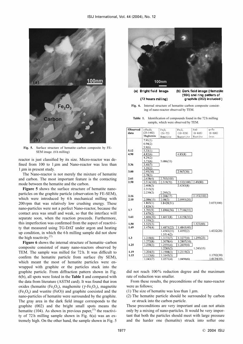
Figure 5 shows the surface structure of hematite nano-particles on the graphite particle (observation by FE-SEM),which were introduced by 6 h mechanical milling with200 rpm that was relatively low crushing energy. Thesenano-particles were not a perfect Nano-reactor, because thecontact area was small and weak, so that the interface willseparate soon, when the reaction proceeds. Furthermore,this imperfection was confirmed from the aspect of reactivi-ty that measured using TG-DAT under argon and heatingup condition, in which the 6 h milling sample did not showthe high reactivity.37)
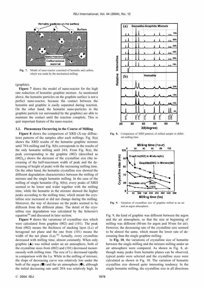
Figure 6 shows the internal structure of hematite–carboncomposite consisted of many nano-reactors observed byTEM. The sample was milled for 72 h. It was difficult toconfirm the hematite particle from surface (by SEM),which meant the most of hematite particles were en-wrapped with graphite or the particles stuck into thegraphite particle. From diffraction pattern shown in Fig.6(b), all spots were listed in the Table 1 and compared withthe data from literature (ASTM card). It was found that ironoxides (hematite (Fe2O3), maghemite (g-Fe2O3), magnetite(Fe3O4) and wustite (FeO)) and graphite coexisted and thenano-particles of hematite were surrounded by the graphite.The gray area in the dark field image corresponds to thegraphite (002) and the bright small spots means thehematite (104). As shown in previous paper,37) the reactivi-ty of 72 h milling sample shown in Fig. 6(a) was an ex-tremely high. On the other hand, the sample shown in Fig. 5
did not reach 100% reduction degree and the maximumrate of reduction was smaller.
From these results, the preconditions of the nano-reactorwere as follows;(1) The size of hematite was less than 1 mm.(2) The hematite particle should be surrounded by carbon
or struck into the carbon particle.These preconditions are very important and can not attainonly by a mixing of nano-particles. It would be very impor-tant that both the particles should meet with large pressureand the harder one (hematite) struck into softer one
ISIJ International, Vol. 44 (2004), No. 12
1977 © 2004 ISIJ
Fig. 5. Surface structure of hematite–carbon composite by FE-SEM image. (6 h milling)
Fig. 6. Internal structure of hematite–carbon composite consist-ing of nano-reactor observed by TEM.
Table 1. Identification of compounds found in the 72 h millingsample, which were observed by TEM.
(graphite).Figure 7 shows the model of nano-reactor for the high
rate reduction of hematite–graphite mixture. As mentionedabove, the hematite particles on the graphite surface is not aperfect nano-reactor, because the contact between thehematite and graphite is easily separated during reaction.On the other hand, the hematite nano-particles in thegraphite particle (or surrounded by the graphite) are able tomaintain the contact until the reaction complete. This isquit important feature of the nano-reactor.
3.2. Phenomena Occurring in the Course of Milling
Figure 8 shows the comparison of XRD (X-ray diffrac-tion) patterns of the samples after each millings. Fig. 8(a)shows the XRD results of the hematite–graphite mixtureuntil 78 h milling and Fig. 8(b) corresponds to the results ofthe only hematite milling until 24 h. From Fig. 8(a), thepeak corresponding to the graphite (002) (described as(002)G) shows the decrease of the crystalline size (the in-creasing of the half-maximum width of peak and the de-creasing of height of peak) with the increasing milling time.On the other hand, the hematite crystalline size showed thedifferent degradation characteristics between the milling ofmixture and the single hematite milling. In the case of themilling of single hematite (Fig. 8(b)), every peaks of XRDseemed to be lower and wider together with the millingtime, while the hematite in the mixture showed the higherpeaks according to the milling time, which meant the crys-talline size increased or did not change during the milling.Moreover, the way of decrease on the peaks seemed to bedifferent from the different plane. The detail of the crys-talline size degradation was calculated by the Scherrer’sequation38) and discussed in later section.
Figure 9 shows the variations of crystalline size whichwere calculated from graphite (002) and (101). The peakfrom (002) means the thickness of stacking layer (Lc) ofhexagonal net plane and the one from (101) means thewidth of the net plane (La).38) Actually, every crystallinedecreased with milling time, almost constantly. When onlygraphite (�) was milled under an air atmosphere, both ofthe crystalline sizes from (002) and (101) decreased monot-onously with milling time. The size of Lc decreased rapidlyin comparison with the La. While in the milling of mixture,the slope of decreasing curve was relatively low under theboth of the argon (�) and the air atmosphere (�), althoughthe initial decreasing rate until 20 h was relatively high. In
Fig. 9, the kind of graphite was different between the argonand the air atmosphere, so that the size at beginning ofmilling was different (80 nm for argon and 50 nm for air).However, the decreasing rate of the crystalline size seemedto be almost the same, which meant the lower rate of de-creasing than the single graphite milling.
In Fig. 10, the variations of crystalline size of hematitebetween the single milling and the mixture milling under anair atmosphere were compared. As shown in Fig. 8, al-though many peaks from hematite planes can be observed,typical peaks were selected and the crystalline sizes werecalculated as shown in Fig. 10. The variation of hematitecrystalline size showed quite interesting tendency. In thesingle hematite milling, the crystalline size in all directions
ISIJ International, Vol. 44 (2004), No. 12
© 2004 ISIJ 1978
Fig. 7. Model of nano-reactor consisted of hematite and carbon,which was made by the mechanical milling.
Fig. 8. Comparison of XRD patterns of milled sample in differ-ent milling time.
Fig. 9. Variation of crystalline size of graphite milled in an airand an argon atmosphere.

(calculated from all peaks) decreased to about 30 nm withthe milling time and the initial decreasing rate was highuntil 6 h. On the other hand, in the milling of mixture,hematite crystalline size showed the different tendencyfrom the plane. The crystalline sizes were almost the sameor slightly increased in (300)H and slightly decreased in(110)H and (104)H, while the size from (300)H was largerthan that from (110)H and (104)H which was caused by theoriginal crystal size. It was considered that the result wouldbe caused by the reduction–reoxidation behavior ofhematite during milling in an air atmosphere. In the case ofreoxidation, the rate of oxidation would be different fromthe plane, which resulted in the different growth rate fromthe plane (anisotropic growth rate).
To confirm the above consideration, the milling of mix-ture in an argon atmosphere was carried out, in which thereoxidation will never occur. Figure 11 shows the compari-son of the crystalline size variation between an air and anargon atmosphere. It was found that the crystalline size ofhematite after milling in an argon atmosphere decreasedcontinuously with the milling time.
The most of milling experiments were carried out withten balls, and the results showed the existence of reductionduring the milling from the gas analysis after milling inargon atmosphere.38) However, in the case of the milling inair, it was difficult to confirm the reduced matter by XRD in
order to reoxidation. Since it was expected that the amountof reduction was very small and the reactivity of the re-duced one would be active, most of reduced matter was re-oxidized as soon as the reduction occurred. From this rea-son, the milling with twenty balls was carried out for con-firming the reduced substance. Figure 12 shows the resultsof XRD for the samples (78 h milling in an air with 10balls, 7 h milling in an argon with 20 balls). The reducedmatter such as magnetite, wustite and iron could not find inthe sample even if the milling time was 78 h in air. On theother hand, small quantity of wustite (Fe0.98O) was found inthe sample milled in an argon, although only 7 h milling.Because of higher energy milling than 10 balls one, alumi-na was fund in the sample after milling.
As mentioned above, the reduced substance (FeO, Fe3O4)was found in the sample milled under the air atmosphere byTEM observation. However, it was quit small quantity todetect by XRD. Anyhow, it could be considered that the re-duction would occur during milling, even in an air atmo-sphere with 10 balls. And these phenomena might increasethe reactivity of milling product intensively.37) In addition tothe simple reduction, it could be considered that the activecomplex which meant the medium product of reductionwould exist and might affect the apparent reactively signifi-cantly. The kinetic analysis taking into account the transi-tion state theory were performed and the active state ofcomplex was considered in the next paper.39)
4. Conclusions
The milling of hematite and graphite mixture was carriedout using alumina vessel under an air and an argon atmo-sphere. The definition of the nano-reactor was conductedfor the understanding of the high reaction rate. Moreover,the phenomena occurring in the course of milling were elu-cidated. The obtained results are as follows:
The preconditions of Nano-reactor are(1) The size of hematite was less than 1 mm.(2) The hematite particle should be surrounded by car-
bon or struck into carbon particle, which support the con-tact between the hematite and the graphite during reactionuntil the reaction complete.
The phenomena occurring in the course of milling.(3) The milling of the single hematite or graphite: The
ISIJ International, Vol. 44 (2004), No. 12
1979 © 2004 ISIJ
Fig. 10. Variation of crystalline size of hematite milled in an airatmosphere.
Fig. 11. Variation of crystalline size of hematite in misturemilled in an air and an argon atmosphere.
Fig. 12. Comparison of XRD patterns of the milled sample be-tween 10 balls in air and 20 balls in argon.

crystalline size decreased regardless of the atmosphere (airor argon).
(4) The milling of the mixture: The reoxidation ofhematite occurred during the milling in an air atmosphere,which resulted in the anisotropic growth of hematite. Onthe other hand, in an argon atmosphere, the hematite crys-talline size decreased constantly because of reduction.
Acknowledgement
The present study has been carried out in the researchgroup of ‘Project for the innovational ironmaking reactionin new blast furnace at half energy consumption and mini-mum environmental influences’ supported by SpecialCoordination Founds of the Science and TechnologyAgency of the Japanese Government. The authors wouldlike to express great appreciation to the member of researchgroup for the valuable discussions.
REFERENCES
1) Y. Uehara: Bull. Chem. Soc. J., 48 (1975), 3383.2) E. Kasai, K. Mae and F. Saito: ISIJ Int., 35 (1995), 1444.3) J. Welham and J. S. Williams: Carbon, 36 (1998), 1309.4) L.-W. Yin, M.-S. Li, Y.-X. Liu, J.-L. Sui and J.-M. Wang: J. Phys.
Condens. Matter, 15 (2003), 309.5) X. Guo, J. Qi and K. Sakurai: Scr. Mater., 48 (2003), 1185.6) L.-W. Yin, M.-S. Li, G. Luo, J.-L. Sui and J.-M. Wang: Chem. Phys.
Lett., 369 (2003), 483.7) K. Kudaka, K. Iizumi, H. Izumi and T. Sasaki: J. Mater. Sci. Lett., 20
(2001), 1619.8) H. L. Castricum, H. Bakker, B. van der Linden and E. K. Poels: J.
Phys. Chem. B, 105 (2001), 7928.9) T. Ido, M. Mori, G. Jin and S. Goto: Kagaku Kogaku Ronbunshu, 72
(2001), 121.10) M. G. Aylmore and F. J. Lincoln: J. Alloys Compounds, 314 (2001),
103.11) G.-L. Tan, X.-J. Wu, M.-H. Zhao and H.-F. Zhang: J. Mater. Sci., 35,
No. 12, (2000), 3151.12) K. Kudaka and K. Iizumi: Mater. Technol., 17 (1999), 391.
13) B. Yao, L. Liu and W. H. Su: J. Appli. Phys., 86 (1999), 2464.14) S. Wada, Y. Kondo, E. Sudo and Y. Maki: J. Ceram. Soc. J., 107
(1999), 611.15) F. Miani and H. J. Fecht: Int. J. Refract. Met. Hard Mater., 17 (1999),
133.16) G.-L. Tan and X.-J. Wu: Powder Metall., 41 (1998), 300.17) F. N. Dzegilenko, D. Srivastava and S. Saini: Nanotechnology, 9
(1998), 330.18) D. L. Zhang and Y. J. Zhang: J. Mater. Sci. Lett., 17 (1998), 1113.19) N. Q. Wu, S. Lin, J. M. Wu and Z. Z. Li: Mater. Sci. Technol., 14
(1998), 287.20) O. S. Morozova, A. N. Streletskii, I. V. Berestetskaya and A. B.
Borunova: Catal. Today, 38 (1997), 107.21) S. Mori, W.-C. Xu; T. Ishidzuki, N. Ogasawara, J. Imai and K.
Kobayashi: Appl. Catal. A: General, 137 (1996), 255.22) M. Sorescu: J. Nanoparticle Res., 2 (2000), 305.23) W. Kim and F. Saito: Powder Technol., 114 (2001), 12.24) G. Mi, Y. Murakami, D. Shindo, F. Saito, K. Shimme and S. Masuda:
Shigen to Sozai, 115 (1999), 683.25) J. Ding, T. Tsuzuki and G. McCormick: Nanostruct. Mater., 8
(1997), 739.26) I. Mitov, Z. Cherkezova-Zheleva and V. Mitrov: Phys. Status Solidi
(a), 161 (1997), 475.27) T. Kosmac and T. H. Courtney: J. Mater. Res., 7 (1992), 1519.28) J. M. Jimenez-Mateos, J. Morales and J. L. Tirado: J. Colloid
Interface Sci., 122 (1988), 507.29) E. Mendelovici, S. Nadiv and I. J. Lin: J. Mater. Sci., 19 (1984),
1556.30) J. L. Rendon, J. Cornejo and P. De Arambarri: J. Colloid Interface
Sci., 94 (1983), 546.31) E. Kasai, T. Kitajima and T. Kawaguchi: ISIJ Int., 40 (2000), 842.32) Q. Wang, Z. Yang, J. Tian, W. Li and J. Sun: Ironmaking
Steelmaking, 24 (1997), 457.33) C. Bryk and W.-K. Lu: Ironmaking Steelmaking, 13 (1986), 70.34) Q. Wang, Z. Yang, J. Tian, W. Li and J. Sun: Ironmaking
Steelmaking, 25 (1998), 443.35) F. Ajersch: Can. Metall. Q., 26 (1987), 137.36) S. K. Dutta and A. Ghosh: Metall. Trans. B, (1994), 15.37) J. Vahdati Khaki, Y. Kashiwaya, Y. Suzuki and K. Ishii: ISIJ Int., 42
(2002), 13.38) Y. Kashiwaya, H. Suzuki and K. Ishii: ISIJ Int., 44 (2004), 1970.39) Y. Kashiwaya and K. Ishii: ISIJ Int., 44 (2004), 1981.
ISIJ International, Vol. 44 (2004), No. 12
© 2004 ISIJ 1980