characteristics of turbulent noise from backward … of turbulent noise from backward-curved...
TRANSCRIPT
Inter-noise 2014 Page 1 of 7
Characteristics of turbulent noise from backward-curved centrifugal
fan with rectangular casing
Hidechito HAYASHI1, Takuma ARAMAKI, Seiji SHIRAHAMA
2, Ippei ODA
3
and Tetsuya OKUMURA4
1,4 Nagasaki University, Japan
2-3 Panasonic Ecology Systems Co., Ltd., Japan
ABSTRACT
The backward-curved centrifugal fan with rectangular casing is used to the air conditioners and the air
cleaners that is required the compact and flexible design. We have studied the fan with rectangular casing by
experiments and numerical simulation. It is pointed out that the performance of the fan with the rectangular
casing is better than that with scroll casing at the large flow rate. The turbulent noise consists of the three
frequency ranges, low frequency range under 800Hz, middle frequency range 1200-2700Hz and high
frequency range 2700-4000Hz, that have the different noise source. The low frequency range is generated
from the impeller, the middle frequency range is mainly generated from the casing wall and the high
frequency range is in relating to the flow above the shroud. The secondary flow near the shroud causes the
large turbulence and generates the high frequency and large turbulent noise. We proposed the obstacle to
reduce the noise level, and then the noise level of high frequency is reduced about 5 dB.
Keywords: Centrifugal fan, Turbulent noise, Room air conditioner:12.4.2
1. INTRODUCTION
The backward-curved centrifugal fan is obtained relatively high efficiency and low noise. The
small size of this type fan is used in the air conditioner and air cleaner. In the application, the fan is
not always used the scroll casing because of the compact arrangement and flexible design of the fan.
In the air cleaner, the impeller is set in the rectangular casing.
The backward-curved centrifugal fans have been studied almost the case with the scroll casing
(1)-(4). The flow characteristics is researched to improve the fan performance (1),(2),(4) and the
interaction between the tongue and the impeller(3),(5). The various geometries of the impeller and
shroud are examined in the performance with experiments (6). For the case of the air conditioner,
there are studies in concerned to the interaction between the impeller and the heat exchanger (7)-(9).
In this case, the air from the fan flows in all directions.
In this paper, It is investigated the characteristics of the turbulent noise in relating to the
interaction between the impeller and the rectangular casing by experiments and numerical simulation.
The turbulent noise is analyzed by dividing the three frequency range. And we proposed the treatment
of setting the obstacle to reduce the noise level.
2. EXPERIMENTS AND SIMULATIONS METHODS
2.1 Experimental Apparatus
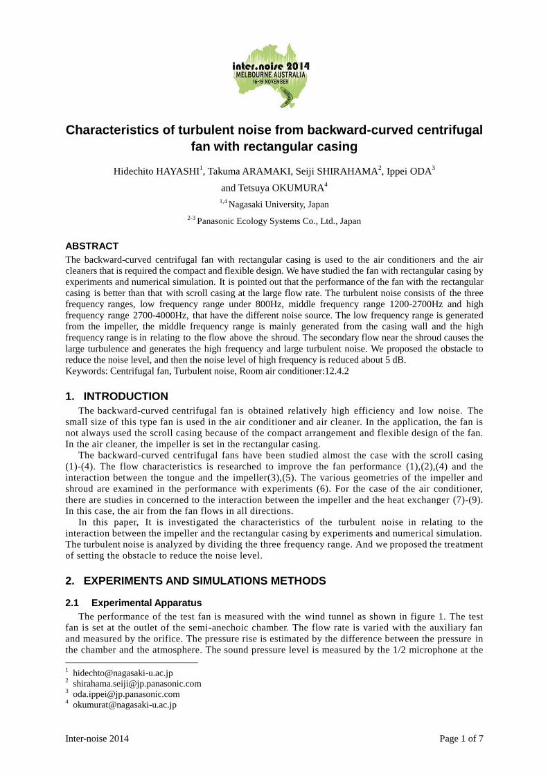
The performance of the test fan is measured with the wind tunnel as shown in figure 1. The test
fan is set at the outlet of the semi-anechoic chamber. The flow rate is varied with the auxiliary fan
and measured by the orifice. The pressure rise is estimated by the difference between the pressure in
the chamber and the atmosphere. The sound pressure level is measured by the 1/2 microphone at the
Page 2 of 7 Inter-noise 2014
Page 2 of 7 Inter-noise 2014
1m upstream from the bell-mouth in the chamber. The sound signal is analyzed by the FFT. The test
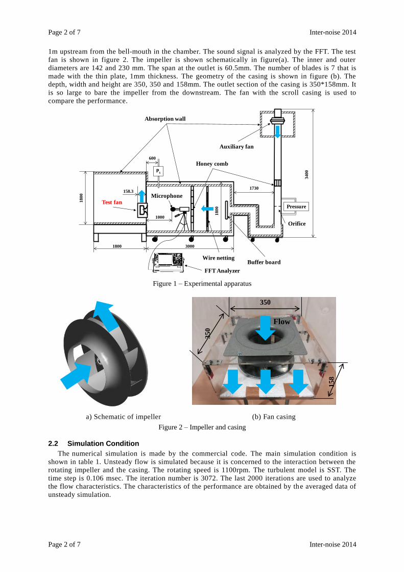
fan is shown in figure 2. The impeller is shown schematically in figure(a). The inner and outer
diameters are 142 and 230 mm. The span at the outlet is 60.5mm. The number of blades is 7 that is
made with the thin plate, 1mm thickness. The geometry of the casing is shown in figure (b). The
depth, width and height are 350, 350 and 158mm. The outlet section of the casing is 350*158mm. It
is so large to bare the impeller from the downstream. The fan with the scroll casing is used to
compare the performance.
Figure 1 – Experimental apparatus
a) Schematic of impeller (b) Fan casing
Figure 2 – Impeller and casing
2.2 Simulation Condition
The numerical simulation is made by the commercial code. The main simulation condition is
shown in table 1. Unsteady flow is simulated because it is concerned to the interaction between the
rotating impeller and the casing. The rotating speed is 1100rpm. The turbulent model is SST. The
time step is 0.106 msec. The iteration number is 3072. The last 2000 iterations are used to analyze
the flow characteristics. The characteristics of the performance are obtained by the averaged data of
unsteady simulation.
Test fan
Buffer board
Honey comb
Orifice
Auxiliary fan
Wire netting
Absorption wall
Ps
Pressure
18
00
3000
1730
3400
FFT Analyzer
Microphone158.3
10001
80
0
600
1800
350
158
350
Flow
Inter-noise 2014 Page 3 of 7
Inter-noise 2014 Page 3 of 7
-0.4
-0.2
0
0.2
0.4
0.6
0.8
1
1.2
0 0.05 0.1 0.15 0.2 0.25 0.3
ψs
ϕ
RC
SC
N=1100[rpm]
Experiment
Table 1 – Simulation condition
Flow condition Unsteady flow
Inlet boundary condition Atmospheric pressure
Outlet boundary condition Mass flow rate
Rotating speed 1100 rpm
Turbulent model SST
Time step 0.106 ms
Iteration number 3072( 6 revolutions)
3. RESULTS AND DISCUSSIONS
3.1 Fluid Performance and Noise Characteristics
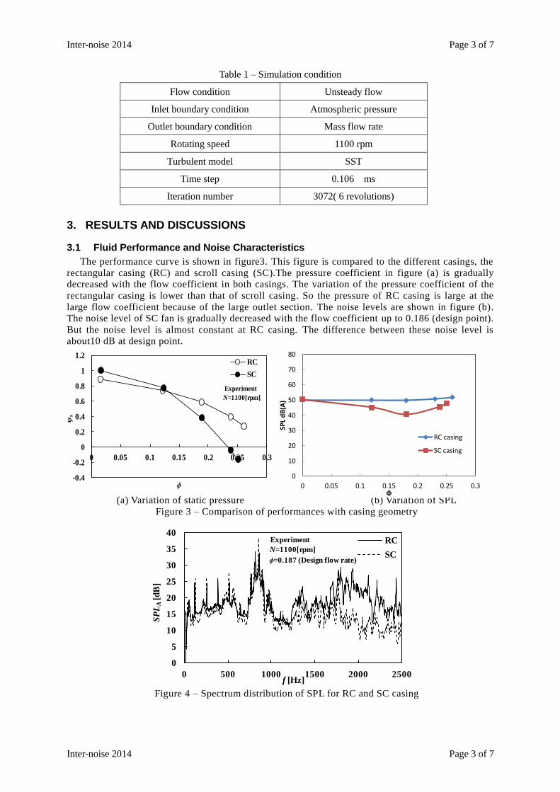
The performance curve is shown in figure3. This figure is compared to the different casings, the
rectangular casing (RC) and scroll casing (SC).The pressure coefficient in figure (a) is gradually
decreased with the flow coefficient in both casings. The variation of the pressure coefficient of the
rectangular casing is lower than that of scroll casing. So the pressure of RC casing is large at the
large flow coefficient because of the large outlet section. The noise levels are shown in figure (b).
The noise level of SC fan is gradually decreased with the flow coefficient up to 0.186 (design point).
But the noise level is almost constant at RC casing. The difference between these noise level is
about10 dB at design point.
(a) Variation of static pressure (b) Variation of SPL
Figure 3 – Comparison of performances with casing geometry
Figure 4 – Spectrum distribution of SPL for RC and SC casing
0
5
10
15
20
25
30
35
40
0 500 1000 1500 2000 2500
SP
LA
[d
B]
f [Hz]
RC
SCN=1100[rpm]
ϕ=0.187 (Design flow rate)
Experiment
0
10
20
30
40
50
60
70
80
0 0.05 0.1 0.15 0.2 0.25 0.3
SPL
dB
(A)
φ
RC casing
SC casing
Page 4 of 7 Inter-noise 2014
Page 4 of 7 Inter-noise 2014
Wall 1
Wall 3
Wall 2
flow
flow
Figure 4 shows the spectral distributions of RC and SC casings. It can be seen that there exists the
discrete frequency noise under the 700Hz caused by the interaction of the impeller and the casing.
The interaction is weak at RC casing(1) The turbulent noise from SC fan is lower than the RC fan.
The difference of sound level in figure 3(b) is mainly caused by the sound over 1700 Hz. At the RC
fan, the turbulent noise over 1700 Hz becomes large compared to the SC fan.
3.2 Flow Characteristics
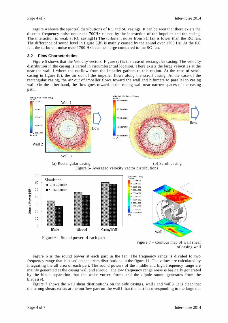
Figure 5 shows that the Velocity vectors. Figure (a) is the case of rectangular casing. The velocity
distribution in the casing is varied in circumferential location. There exists the large velocities at the
near the wall 1 where the outflow from the impeller gathers to this region. At the case of scroll
casing in figure (b), the air out of the impeller flows along the scroll casing. At the case of the
rectangular casing, the air out of impeller flows toward the wall and bifurcate to parallel to casing
wall. On the other hand, the flow goes toward to the casing wall near narrow spaces of the casing
path.
(a) Rectangular casing (b) Scroll casing
Figure 5- Averaged velocity vector distributions
Figure 6 – Sound power of each part
Figure 7 – Contour map of wall shear
of casing wall
Figure 6 is the sound power at each part in the fan. The frequency range is divided to two
frequency range that is based on spectrum distributions in the figure 11. The values are calculated by
integrating the all area of each part. The sound powers of the middle and high frequency range are
mainly generated at the casing wall and shroud. The low frequency range noise is basically generated
by the blade separation that the wake vortex forms and the dipole sound generates from the
blades(9).
Figure 7 shows the wall shear distributions on the side casings, wall1 and wall3. It is clear that
the strong shears exists at the outflow part on the wall1 that the part is corresponding to the large out
Wall 1
Wall 3
Inter-noise 2014 Page 5 of 7
Inter-noise 2014 Page 5 of 7
flow part as shown in figure 5. On the wall 3, the strong shear exists at the upper side. This location
is not corresponding to the flow from the impeller.
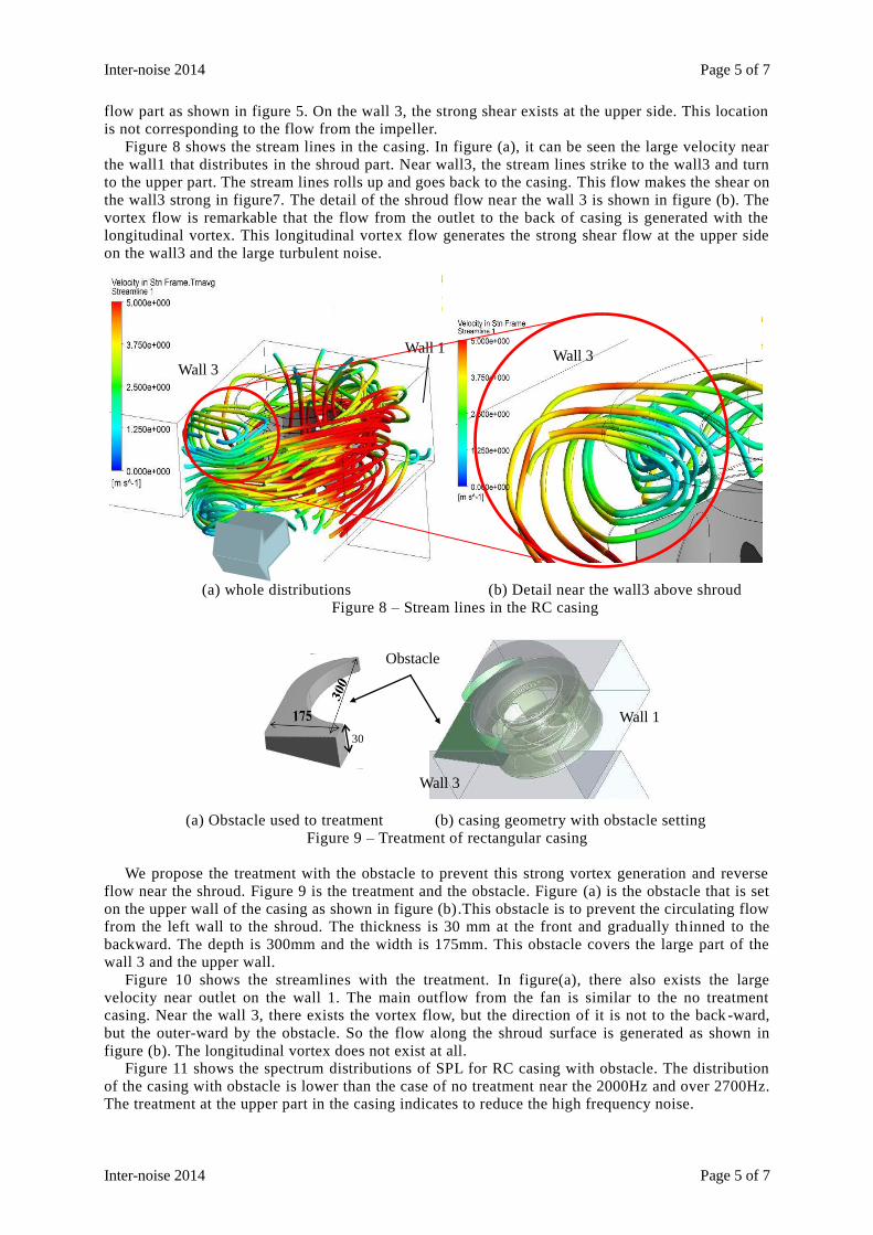
Figure 8 shows the stream lines in the casing. In figure (a), it can be seen the large velocity near
the wall1 that distributes in the shroud part. Near wall3, the stream lines strike to the wall3 and turn
to the upper part. The stream lines rolls up and goes back to the casing. This flow makes the shear on
the wall3 strong in figure7. The detail of the shroud flow near the wall 3 is shown in figure (b). The
vortex flow is remarkable that the flow from the outlet to the back of casing is generated with the
longitudinal vortex. This longitudinal vortex flow generates the strong shear flow at the upper side
on the wall3 and the large turbulent noise.
(a) whole distributions (b) Detail near the wall3 above shroud
Figure 8 – Stream lines in the RC casing
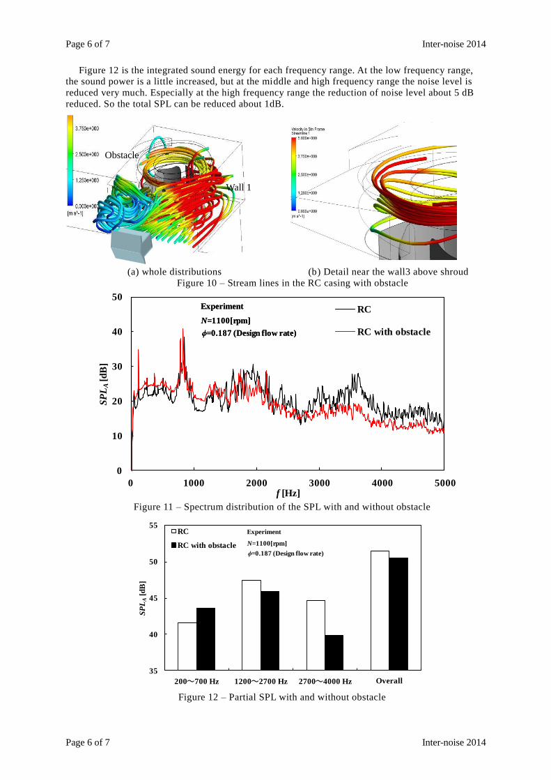
(a) Obstacle used to treatment (b) casing geometry with obstacle setting
Figure 9 – Treatment of rectangular casing
We propose the treatment with the obstacle to prevent this strong vortex generation and reverse
flow near the shroud. Figure 9 is the treatment and the obstacle. Figure (a) is the obstacle that is set
on the upper wall of the casing as shown in figure (b).This obstacle is to prevent the circulating flow
from the left wall to the shroud. The thickness is 30 mm at the front and gradually thinned to the
backward. The depth is 300mm and the width is 175mm. This obstacle covers the large part of the
wall 3 and the upper wall.
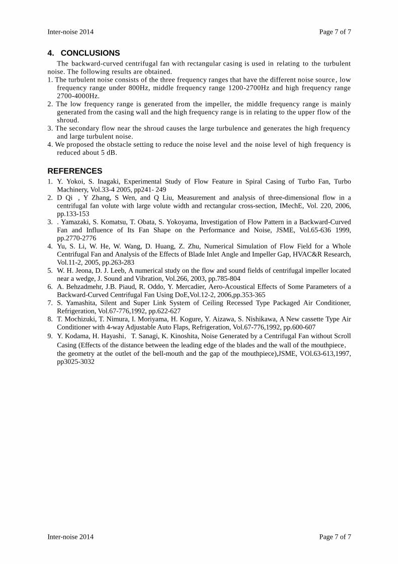
Figure 10 shows the streamlines with the treatment. In figure(a), there also exists the large
velocity near outlet on the wall 1. The main outflow from the fan is similar to the no treatment
casing. Near the wall 3, there exists the vortex flow, but the direction of it is not to the back -ward,
but the outer-ward by the obstacle. So the flow along the shroud surface is generated as shown in
figure (b). The longitudinal vortex does not exist at all.
Figure 11 shows the spectrum distributions of SPL for RC casing with obstacle. The distribution
of the casing with obstacle is lower than the case of no treatment near the 2000Hz and over 2700Hz.
The treatment at the upper part in the casing indicates to reduce the high frequency noise.
Wall 1
Wall 3 Wall 3
30
Wall 1
Wall 3
Obstacle
Page 6 of 7 Inter-noise 2014
Page 6 of 7 Inter-noise 2014
0
10
20
30
40
50
0 1000 2000 3000 4000 5000
SP
LA
[dB
]
f [Hz]
RC
RC with obstacle
N=1100[rpm]
ϕ=0.187 (Design flow rate)
Experiment
N=1100[rpm]
ϕ=0.187 (Design flow rate)
Experiment
35
40
45
50
55
200 700 Hz 1200 2700 Hz 2700 4000 Hz Overall
SP
LA
[dB
]
RC
RC with obstacle N=1100[rpm]
ϕ=0.187 (Design flow rate)
Experiment
Figure 12 is the integrated sound energy for each frequency range. At the low frequency range,
the sound power is a little increased, but at the middle and high frequency range the noise level is
reduced very much. Especially at the high frequency range the reduction of noise level about 5 dB
reduced. So the total SPL can be reduced about 1dB.
(a) whole distributions (b) Detail near the wall3 above shroud
Figure 10 – Stream lines in the RC casing with obstacle
Figure 11 – Spectrum distribution of the SPL with and without obstacle
Figure 12 – Partial SPL with and without obstacle
Wall 1
Obstacle
Inter-noise 2014 Page 7 of 7
Inter-noise 2014 Page 7 of 7
4. CONCLUSIONS
The backward-curved centrifugal fan with rectangular casing is used in relating to the turbulent
noise. The following results are obtained.
1. The turbulent noise consists of the three frequency ranges that have the different noise source , low
frequency range under 800Hz, middle frequency range 1200-2700Hz and high frequency range
2700-4000Hz.
2. The low frequency range is generated from the impeller, the middle frequency range is mainly
generated from the casing wall and the high frequency range is in relating to the upper flow of the
shroud.
3. The secondary flow near the shroud causes the large turbulence and generates the high frequency
and large turbulent noise.
4. We proposed the obstacle setting to reduce the noise level and the noise level of high frequency is
reduced about 5 dB.
REFERENCES
1. Y. Yokoi, S. Inagaki, Experimental Study of Flow Feature in Spiral Casing of Turbo Fan, Turbo
Machinery, Vol.33-4 2005, pp241- 249
2. D Qi�, Y Zhang, S Wen, and Q Liu, Measurement and analysis of three-dimensional flow in a
centrifugal fan volute with large volute width and rectangular cross-section, IMechE, Vol. 220, 2006,
pp.133-153
3. . Yamazaki, S. Komatsu, T. Obata, S. Yokoyama, Investigation of Flow Pattern in a Backward-Curved
Fan and Influence of Its Fan Shape on the Performance and Noise, JSME, Vol.65-636 1999,
pp.2770-2776
4. Yu, S. Li, W. He, W. Wang, D. Huang, Z. Zhu, Numerical Simulation of Flow Field for a Whole
Centrifugal Fan and Analysis of the Effects of Blade Inlet Angle and Impeller Gap, HVAC&R Research,
Vol.11-2, 2005, pp.263-283
5. W. H. Jeona, D. J. Leeb, A numerical study on the flow and sound fields of centrifugal impeller located
near a wedge, J. Sound and Vibration, Vol.266, 2003, pp.785-804
6. A. Behzadmehr, J.B. Piaud, R. Oddo, Y. Mercadier, Aero-Acoustical Effects of Some Parameters of a
Backward-Curved Centrifugal Fan Using DoE,Vol.12-2, 2006,pp.353-365
7. S. Yamashita, Silent and Super Link System of Ceiling Recessed Type Packaged Air Conditioner,
Refrigeration, Vol.67-776,1992, pp.622-627
8. T. Mochizuki, T. Nimura, I. Moriyama, H. Kogure, Y. Aizawa, S. Nishikawa, A New cassette Type Air
Conditioner with 4-way Adjustable Auto Flaps, Refrigeration, Vol.67-776,1992, pp.600-607
9. Y. Kodama, H. Hayashi,T. Sanagi, K. Kinoshita, Noise Generated by a Centrifugal Fan without Scroll
Casing (Effects of the distance between the leading edge of the blades and the wall of the mouthpiece,the geometry at the outlet of the bell-mouth and the gap of the mouthpiece),JSME, VOl.63-613,1997,
pp3025-3032