characterization and identification of … · lénia fernandes characterization and identification...
TRANSCRIPT

Departamento de Conservação e Restauro
Faculdade de Ciências e Tecnologia
Universidade de Nova de Lisboa
CC HARACTERIZATION AND HARACTERIZATION AND IIDENTIFICATION OF DENTIFICATION OF
PPRINTED RINTED OOBJECTSBJECTS
Lénia Janete Oliveira Fernandes
nº 25988
Dissertação de Mestrado em Conservação e Restauro
Área de Documentos Gráficos - Fotografia
Orientação: Prof. Doutor José Ramos (FBA-UL/FCT-UNL)
Ryan Boatright e Gawain Weaver (IPI-RIT)
11 de Julho de 2008

INDEX
Abstract……………………………………………………………………………………………. 1
Introduction……………………………………………………………………………………….. 1
Characterization and Identification of Printed Objects………………………………….. 2
Pre-photographic processes………………………………………………………….. 2
Woodcut………………………………………….…………………………….. 3
Engraving………………………………………….…………………………… 3
Etching………………………………………….……………………………… 3
Lithography……………………………………………………………………. 4
Photomechanical processes………………………………………………………….. 5
Collotype……………………………………………………………………….. 6
Woodburytype…………………………………………………………………. 7
Photogravure………………………………………………………………….. 8
Rotogravure……………………………………………………………………. 8
Letterpress Halftone………………………………………………………….. 9
Offset Lithography…………………………………………………………….. 10
Photographic processes ………………………………………………………………. 12
Printing out processes………………………………………………………... 12
Salted paper print……………………………………………………. 12
Albumen print……..…………………………………………………. 12
Collodion P.O.P. ……………………………………………………. 14
Gelatin P.O.P. ………………………………………………………. 16
Non-silver processes…………………………………………………………. 16
Carbon………………………………………………………………... 16
Color Photography……………………………………………………………. 18
Ansco Printon………………………………………………………... 19
Agfacolor prints……………………………………………………… 19
Kodachrome…………………………………………………………. 19
Cibachrome………………………………………………………….. 21
Digital Photography…………………………………………………………………….. 22
Electrophotography…………………………………………………………… 22
Dye Sublimation (D2T2) …………………………………………………….. 24
Inkjet prints………………………………………….…………………………. 25

Conclusions………………………………………….…………………………………………… 27
Acknowledgements……………………………………….…………………………………… 28
References………………………………………….…………………………………………….. 29
Appendix………………………………………….……………………………………………….. 32
Appendix I – Experimental…………………………………………………………….. 32
Camera and system calibration……………………………………………… 32
Copystand……………………………………………………………………… 33
Photomicrography…………………………………………………………….. 37
Microscope…………………………………………………………… 37
Microtome……………………………………………………………. 40
Stereomicroscope…..………………………………………………………… 41
Appendix II – Print technology illustrations………………………………………….. 42
Appendix III – Other images…………………………………………………………… 50
Appendix IV - Tables…………………………………………………………………… 52

Lénia FernandesLénia Fernandes Characterization and Identif ication of Printed ObjectsCharacterization and Identif ication of Printed Objects
1
ABSTRACT
A study about the physical appearance of pre-photographic, photomechanical, photographic
and digital positive reflective prints was made, relating the obtained images with the history,
materials and technology used to create them. The studied samples are from the Image
Permanence Institute (IPI) study collection. The digital images were obtained using a digital
SLR on a copystand and a compound light microscope, with different lighting angles (0º, 45º
and 90º) and magnifications from overall views on the copystand down to a 20x objective lens
on the microscope. Most of these images were originally created by IPI for
www.digitalsamplebook.org, a web tool for teaching print identification, and will be used on
the www.graphicsatlas.org website, along with textual information on identification,
technology and history information about these reproduction processes.
Keywords: identification, characterization, prints, pre-photographic, photographic, digital
photography, copystand, macrophotography, microphotography, cross-sections, UV light.
INTRODUCTION
Images made through reproductions processes have been created over the past 700 years in
many ways. At first these images were made by hand, but technological innovations have
allowed the chemical, optical, and mechanical capture and reproduction of images. Since the
beginning of the 19th century, these developments permitted a more accurate representation
of reality. Throughout the 19th and 20th centuries, photography evolved to create ever more
realistic images, and generating them faster, and with greater sharpness, permanence, and
even color. The development of digital imaging, particularly over the last 20 years, represents
the highest technological development in photography [1].
The Image Permanence Institute (IPI), at the Rochester Institute of Technology (RIT),
in Rochester (NY) – U.S.A., was founded in 1985 to conduct research on the deterioration
and preservation of photographic materials. Since then, IPI has greatly expanded existing
conservation knowledge, particularly in this field. One of the IPI’s current projects is the
development of new tools to explore graphic materials and an image methodology to
characterize and identify them, and to present this research in an accessible and useful way
to conservators, curators, art historians, collectors and students. On
www.digitalsamplebook.org, different images of prints are shown [2, 3]. Based on the original
website, a new, enhanced one, www.graphicsatlas.org will be launched. It will feature the
original image viewing tool “Object Explorer”, and will include pages on the identification,
history and technology of each of the photographic and printing processes illustrated.
Educating individuals in the identification and understanding of prints is a necessary basis for

Lénia FernandesLénia Fernandes Characterization and Identif ication of Printed ObjectsCharacterization and Identif ication of Printed Objects
2
a more accurate preservation of photographic materials, giving them meaning and creating
awareness in those who care for them [4].
In this paper, descriptions of different materials and techniques are made, supported
by the imaging techniques described in Appendix I (pp. 32-41). The examples presented were
chosen as representative of each process, but cannot represent all the variants of each
process that were (and in some cases, continue to be) created. Well-established commercial
processes often tend to perfect its technology, contributing for their diversity. The appearance
of a print can also be dramatically affected by deterioration, which constitutes as another
factor to have in mind when describing them.
This work is composed of general descriptions of processes selected from the
www.digitalsamplebook.org website, that will accompany them in the www.graphicsatlas.org
site, in the appropriate sections. For example, developing-out gelatin silver prints are being
studied in more depth by Ryan Boatright and the characterization team at IPI, focusing on the
great variations this same process allowed, based mostly on Kodak samples; iron based
photography, as the name points out, isn’t based on the light sensitivity of silver salts nor is
related with the materials used in the manufacture of photomechanical prints (as opposed to
carbon prints, included in the text); instant photography is a very complex subject, since the
final print is also the same object that was exposed to light and developed chemically, and
therefore different from the approached processes.
CHARACTERIZATION AND IDENTIFICATION OF PRINTED OBJECTS
Pre-photographic processes
This type of process is defined here as those used for reproduction of prints that do not use
any photosensitive materials at any point in their creation. The resulting prints are composed
of a paper support with transferred ink. They are generally separated into three primary
printing methods: intaglio, relief, and planographic (Appendix II, Figure 132) [1].
The pre-photographic processes mentioned in www.digitalsamplebook.org are
etching, gravure, woodcut, and lithography. Other processes, mainly variations of the intaglio
process, like aquatint and mezzotint, are not studied here [1, 2].
Pre-photographic techniques are defined according to where the ink sits on the
printing plate to then be transferred onto a dampened paper support (generally made from
rag fibers such as linen and cotton). This has an impact on the final physical appearance of
the print. In the relief process, height differences are created in the printing plate, so the ink is
placed on its surface rather than its groves. Woodcut is a relief process, obtained from
carving a wood block and inking its surface. The opposite happens in intaglio plates, since the
ink is pressured out of the depressions while its surface remains clean. Gravures and
etchings are intaglio processes, prepared on metallic surfaces, usually copper. To transfer the
ink into paper great pressure is required, which explains the plate marks that accompany this

Lénia FernandesLénia Fernandes Characterization and Identif ication of Printed ObjectsCharacterization and Identif ication of Printed Objects
3
type of prints, when they aren’t cropped. Planographic processes don’t need to use depth
differences in the printing plate. Instead, it relies on the repulsion of water and oil based inks.
Lithography is a planographic process, where an image is created over a stone surface
(Appendix II, Figure 132). [1, 5, 6]
Image structure depends on the technique used. Woodcuts, popularized in Europe
in the early 14th century, have dark image areas corresponding to where the wood block
wasn’t carved and the black greasy ink was applied with a dabber. Non-image areas match
regions where the wood was taken out with a sharp tool, and didn’t come in contact with the
paper surface. Gradations are difficult to obtain through carving, so most prints have good
definition between inked and non-image areas (Figures 1-2). The evolution of the technique
allowed greater detail, but woodcuts lost their appeal with the popularization of intaglio
processes in the 16th century. In the 19th century they were reutilized for reproduction of
illustrations in magazines and books [1, 7-9].
Engravings were first used in the mid-15th century, and are commonly found in 17th
and 18th century book illustrations. A tool called burin was used to make depressions on a
surface (usually metal), creating line or dot shapes [9]. Consequently, these forms, where the
ink gets deposited, compose the image, while non-image areas, on the surface of the plate,
are cleaned and don’t transfer any ink into the paper (Figures 3-4; Appendix II, Figure 132).
Etchings were made by drawing with a sharp needle point over an asphalt-covered
plate. After the design was incised, the resin was taken out on those areas, exposing the
metal. The plate went into an acid etching bath, using different acids for different metals. The
exposed metal was etched and an image was produced on the plate. Corrections could be
done, a great advantage over other techniques. They could be done by reapplying resin over
the plate, after it was scraped and burnished to cover the etched line. The longer the bath, the
more ink the plate could retain. Darker areas have more ink, and this relief may create
differential gloss (but not in this sample) (Figures 5-7; Appendix II, Figure 132) [1, 7, 8, 10].
Figures 1 and 2 – Woodcut. Normal view and 50x view (left to right) at 45º lighting. The dark image areas are well defined.
Figures 3 and 4 – Engraving. Normal and macro views (left to right) at 45º lighting. The image is composed of more detailed lines.

Lénia FernandesLénia Fernandes Characterization and Identif ication of Printed ObjectsCharacterization and Identif ication of Printed Objects
4
Senefelder introduced lithography and planographic processes in the late 18th
century. Lithographs were made on polished stone surfaces (like limestone’s, but in modern
times metal or plastic are used). A drawing is made with a greasy crayon; an acidic water
solution with gum arabic is spread on the surface, filling the limestone pores where the crayon
wasn’t used. Oil-based ink is then applied to the surface, adhering to the crayon, and being
repelled by the water filling non-image areas. The applied ink is transferred to a paper support
in a lithographic press. The obtained image lacks relief, since the ink layer is thin and it’s
printed from a plate or stone with no relief or incisions (planographic) (Figures 8-9; Appendix
II, Figure 132). It’s a versatile technique that can be difficult to identify, if it emulates
characteristics of other processes [1, 7-9, 11].
At high magnification paper fibers of pre-photographic prints can be seen, particularly
in non-image areas (Figures 10-13). They only have a paper layer covered with greasy ink,
since it doesn’t penetrate the paper fibers. Cross-sections show the variation on thickness of
paper bases and how the ink is it deposited on its surface (Figures 14-15). Rag paper is a
non-fluorescent material (Appendix II, Figures 149-150) [5]. See also Table I, Appendix IV.
Figure 5 – Etching. Normal view at 45º lighting.
Figure 6 – Etching. Macro view at 45º lighting. The dark areas are the ones with more ink.
Figure 7 – Etching. Macro view with 90º lighting. This lighting reveals the texture of the darker areas and their relief.
Figure 8 – Lithogravure. Normal view with 45º lighting.
Figure 9 – Lithogravure. Macro view with 45º lighting. There are no significant changes when viewed under 90º lighting.

Lénia FernandesLénia Fernandes Characterization and Identif ication of Printed ObjectsCharacterization and Identif ication of Printed Objects
5
Photomechanical processes
Photomechanical processes combined machinery like the ones used for traditional
printmaking with photographic techniques to create a photographic image printed in ink. The
final print doesn’t have light sensitive material to record the image, and often (but not always)
presents a patterned image when observed under magnification. The pattern was specific to
each process, making this a good identification characteristic [4, 12, 13]. All the
photomechanical prints mentioned in www.digitalsamplebook.org are approached here [2].
Like the pre-photographic processes, and with the exception of Woodburytypes, the
images are formed by oil-based inks mixed with pigments with very high stability [14]. The
paper support could of rag paper or wood pulp, depending on when it was made and the
quality of the print (cheaper prints were often done on the less expensive wood pulp papers,
that has less quality). Sometimes a surface coating was placed on the paper, to smooth it and
give more image definition, a practice common after the 1850s (Figure 34) [1].
Before the 20th century, dichromated gelatin was used in some stage of the
production of photomechanical prints, to create the image mould. When gelatin is mixed with
chromium salts, it hardens when exposed to light and becomes insoluble in water. Mungo
Ponton first discovered this effect in 1839. After light exposure in contact with a positive or
negative transparency, the surface containing the gelatin was washed in hot water, removing
Figures 10-13 – Woodcut, engraving, etching and lithograph (left to right), seen at 50x with 90º lighting. In all the examples paper fibers are visible, even under the ink layer.
Figures 14 and 15 – Engraving and etching (left to right). Cross sections at 200x, with BF reflected light. In this case, the ink layer on the engraving is thicker than the one on the etching, while they have opposite
proportions in what concerned the thickness of the support.

Lénia FernandesLénia Fernandes Characterization and Identif ication of Printed ObjectsCharacterization and Identif ication of Printed Objects
6
the unexposed, soft gelatin. The relief gelatin mold was used accordingly to the technique the
print was made in, which is described in the following paragraphs. With a press, the inked
plate was placed against a dampened sheet of paper, like in traditional printing techniques [1,
13, 15].
In 1855, Poitevin invented the collotype process. Josef Albert improved the
manufacturing process in 1873 by using a rotary press. By 1876 he was producing colored
collotypes [16]. Collotypes were used for high quality reproductions of photographs, at the
time obtained through wet plate negatives, but also reproductions of drawings and
watercolors. It was used in postcards and book illustrations until the 1960s (Figures 16-19) [1,
4, 9, 12, 14, 17, 18].
Collotypes were obtained through a glass or metal plate covered with dichromated
gelatin. It was exposed to light with a negative, and washed (Appendix II, Figure 133). The
reticulation pattern was obtained by washing the plate in cold water after it had been heated
on an oven. The expanded gelatin was forced to shrink with the contrasting temperatures
(Appendix II, Figure 134). The result was a reticulated, cracked surface. The dried plate was
inked and then pressed into a smooth surface paper support, creating the final print (Figures
16-19). Because the ink stayed on the surface of the plate, this is considered a planographic
process, creating a surface that doesn’t have differential gloss. The amount of applied
pressure was relatively small, not creating plate marks [1, 4, 17, 19].
Figure 16 – Collotype. Normal view at 45º lighting. Figure 17 – Collotype. 50x view at 45º lighting. The pattern is formed across the inked areas.
Figure 18 – Color collotype. Normal view at 45º lighting.
Figure 19 – Color collotype. 50x view at 45º lighting. Each color layer presents the reticulation pattern.

Lénia FernandesLénia Fernandes Characterization and Identif ication of Printed ObjectsCharacterization and Identif ication of Printed Objects
7
W.B. Woodbury invented the Woodburytype in 1864-65, with a patent published in
the British Journal of Photography. By the 1870s it was an established method for
photographic reproduction and to print illustrations in books. They weren’t made in large
formats, due to the great pressure needed in the process, which could not be obtained
uniformly over very large areas. Like carbon prints (see p. 16-18), these prints were
advertised as a permanent method. By 1900 other photomechanical processes, such as
letterpress halftone, made Woodburytypes too expensive by comparison, leading to the
abandonment of the method [4, 13, 16, 19-21].
Although it is a photomechanical process, the woodburytype has a continuous-tone
image (Figures 20-21). It’s obtained in the following way: a dichromated gelatin layer is
printed in contact with a photographic negative. The gelatin layer is then washed and dried,
producing a gelatin relief image (Appendix II, Figure 133). This was then used as a mould to
produce a relief image in a soft metal plate, usually lead. To maintain the relief of the lead
plate, and consequently the print’s quality, the metal plate was covered with chromium.
Pigmented gelatin (not light sensitive) was pored on the cast, and the plate was pressed
against paper. The relief of colored gelatin was then on paper (Appendix II, Figure 135) [19].
Pigment particles may be seen across the surface of the print, at high magnification. Darker
areas have thicker gelatin layers, while non-image areas continue to show paper fibers from
the support. To harden the gelatin layer, woodburytypes went through an alum bath [4, 12,
13, 16].
Woodburytypes exhibit differential gloss due to the difference in gelatin thickness
between image and non-image areas (Figure 21-22). Also, due to deterioration, cracks in
dark image areas are common. The expansion and contraction rates of gelatin and paper
when exposed to changes in relative humidity is different, creating stress in the gelatin layer
that is released by the formation of cracks [4, 17].
Figures 21 and 22 – Woodburytype. Macro view at 45º and 0º lighting (left to right). The darker areas have more gelatin, creating differential gloss. In this case, it also shows cracks.
Figure 20– Woodburytype. Normal view at 45º lighting.
Lénia FernandesLénia Fernandes Characterization and Identif ication of Printed ObjectsCharacterization and Identif ication of Printed Objects
8
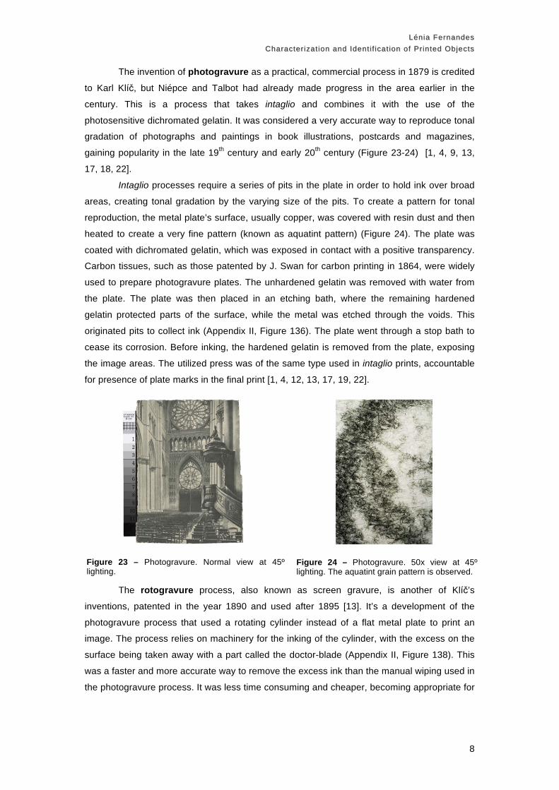
The invention of photogravure as a practical, commercial process in 1879 is credited
to Karl Klíč, but Niépce and Talbot had already made progress in the area earlier in the
century. This is a process that takes intaglio and combines it with the use of the
photosensitive dichromated gelatin. It was considered a very accurate way to reproduce tonal
gradation of photographs and paintings in book illustrations, postcards and magazines,
gaining popularity in the late 19th century and early 20th century (Figure 23-24) [1, 4, 9, 13,
17, 18, 22].
Intaglio processes require a series of pits in the plate in order to hold ink over broad
areas, creating tonal gradation by the varying size of the pits. To create a pattern for tonal
reproduction, the metal plate’s surface, usually copper, was covered with resin dust and then
heated to create a very fine pattern (known as aquatint pattern) (Figure 24). The plate was
coated with dichromated gelatin, which was exposed in contact with a positive transparency.
Carbon tissues, such as those patented by J. Swan for carbon printing in 1864, were widely
used to prepare photogravure plates. The unhardened gelatin was removed with water from
the plate. The plate was then placed in an etching bath, where the remaining hardened
gelatin protected parts of the surface, while the metal was etched through the voids. This
originated pits to collect ink (Appendix II, Figure 136). The plate went through a stop bath to
cease its corrosion. Before inking, the hardened gelatin is removed from the plate, exposing
the image areas. The utilized press was of the same type used in intaglio prints, accountable
for presence of plate marks in the final print [1, 4, 12, 13, 17, 19, 22].
The rotogravure process, also known as screen gravure, is another of Klíč’s
inventions, patented in the year 1890 and used after 1895 [13]. It’s a development of the
photogravure process that used a rotating cylinder instead of a flat metal plate to print an
image. The process relies on machinery for the inking of the cylinder, with the excess on the
surface being taken away with a part called the doctor-blade (Appendix II, Figure 138). This
was a faster and more accurate way to remove the excess ink than the manual wiping used in
the photogravure process. It was less time consuming and cheaper, becoming appropriate for
Figure 23 – Photogravure. Normal view at 45º lighting.
Figure 24 – Photogravure. 50x view at 45º lighting. The aquatint grain pattern is observed.
Lénia FernandesLénia Fernandes Characterization and Identif ication of Printed ObjectsCharacterization and Identif ication of Printed Objects
9
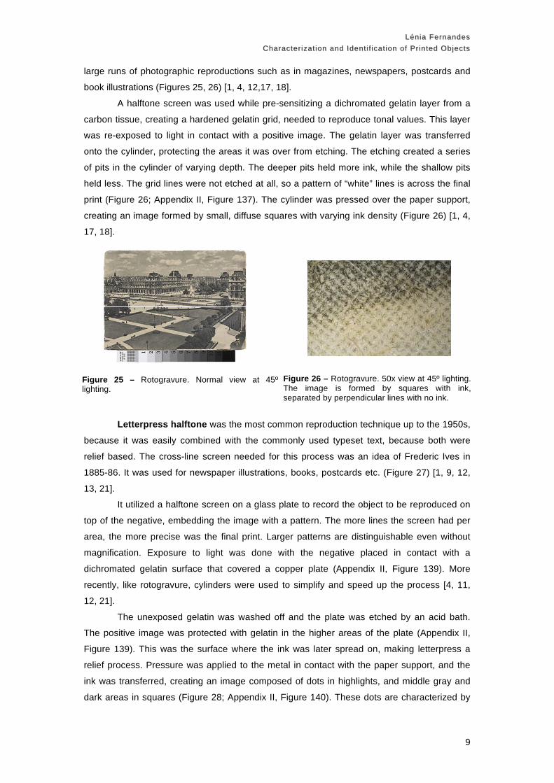
large runs of photographic reproductions such as in magazines, newspapers, postcards and
book illustrations (Figures 25, 26) [1, 4, 12,17, 18].
A halftone screen was used while pre-sensitizing a dichromated gelatin layer from a
carbon tissue, creating a hardened gelatin grid, needed to reproduce tonal values. This layer
was re-exposed to light in contact with a positive image. The gelatin layer was transferred
onto the cylinder, protecting the areas it was over from etching. The etching created a series
of pits in the cylinder of varying depth. The deeper pits held more ink, while the shallow pits
held less. The grid lines were not etched at all, so a pattern of “white” lines is across the final
print (Figure 26; Appendix II, Figure 137). The cylinder was pressed over the paper support,
creating an image formed by small, diffuse squares with varying ink density (Figure 26) [1, 4,
17, 18].
Letterpress halftone was the most common reproduction technique up to the 1950s,
because it was easily combined with the commonly used typeset text, because both were
relief based. The cross-line screen needed for this process was an idea of Frederic Ives in
1885-86. It was used for newspaper illustrations, books, postcards etc. (Figure 27) [1, 9, 12,
13, 21].
It utilized a halftone screen on a glass plate to record the object to be reproduced on
top of the negative, embedding the image with a pattern. The more lines the screen had per
area, the more precise was the final print. Larger patterns are distinguishable even without
magnification. Exposure to light was done with the negative placed in contact with a
dichromated gelatin surface that covered a copper plate (Appendix II, Figure 139). More
recently, like rotogravure, cylinders were used to simplify and speed up the process [4, 11,
12, 21].
The unexposed gelatin was washed off and the plate was etched by an acid bath.
The positive image was protected with gelatin in the higher areas of the plate (Appendix II,
Figure 139). This was the surface where the ink was later spread on, making letterpress a
relief process. Pressure was applied to the metal in contact with the paper support, and the
ink was transferred, creating an image composed of dots in highlights, and middle gray and
dark areas in squares (Figure 28; Appendix II, Figure 140). These dots are characterized by
Figure 25 – Rotogravure. Normal view at 45º lighting.
Figure 26 – Rotogravure. 50x view at 45º lighting. The image is formed by squares with ink, separated by perpendicular lines with no ink.

Lénia FernandesLénia Fernandes Characterization and Identif ication of Printed ObjectsCharacterization and Identif ication of Printed Objects
10
having well defined edges, where the ink concentrates because of the pressure applied to
squeeze it out on the paper. The pressure was also applied to characters, so the print has
differences in relief in the text [1, 4, 11]
The principle of offset lithography (also known as offset litho) was conceived in the
mid 19th century, but it wasn’t practically applied before 1910, when the offset press was
invented. It was increasingly used during World War II, and by the 1960s it became the most
common printing process, replacing letterpress. Offset litho has been used for newspapers,
books, labels, posters, greeting cards, etc. (Figures 29, 30) [1, 9, 11, 14, 22].
Technically, offset litho prints are made in the same surface as photolithographs,
covered with a layer of dichromated gelatin. It’s exposed to light in contact with a halftone
negative holding an image originally captured with a halftone screen or by using the negative
in contact with the screen at the moment of exposure. As lithography, the image is
constructed by the opposite properties of water and oily ink (Appendix II, Figure 141). It
evolved to rotary cylinders to speed up the process, like rotogravure. When it’s time to print
the image, the ink isn’t directly transferred onto the paper support, hence the offset stage of
the process. Instead, it goes from the lithographic surface to a rubber roller/blanket, and
finally transferred to the paper (Appendix II, Figure 142) [1, 11, 14, 22].
The final result is visually similar to the one achieved by letterpress halftone, because
of the common use of a halftone screen to break up the image. To distinguish these two
processes, it is necessary to look into the pattern structure. In offset lithographs, the ink tends
to diffuse around the edges of the dots, while in letterpress the ink concentrates around the
edges because of the squeeze out (Figures 28, 30) [1].
Figure 27 – Color letterpress halftone. Normal view at 45º lighting.
Figure 28 – Color letterpress halftone. 50x view at 45º lighting. The dots show squeeze out along the edges. Middle tones have square to circular dots, while in dark areas the square dots are merged by the edges.
Figure 29 – Color offset lithograph. Normal view at 45º lighting.
Figure 30 – Color offset lithograph. 50x view at 45º lighting. The pattern isn’t as sharp as the one shown by letterpress halftone prints.

Lénia FernandesLénia Fernandes Characterization and Identif ication of Printed ObjectsCharacterization and Identif ication of Printed Objects
11
Like pre-photographic prints, photomechanical prints don’t usually have other layers
besides the paper support and the ink. Therefore, when observed under the microscope, it is
possible to see paper fibers, in the case of the Woodburytype only in non-image areas
(Figures 431-33) [4]. In the case of the samples used, in the letterpress halftone example the
paper fibers aren’t visible because, as seen in cross-section, there’s an extra layer in the
paper. This is a finishing layer applied to the paper, which is probably coated with china clay
(kaolin, an hydrated aluminum silicate) to provide extra smoothness and more compatibility
with the ink. Under UV light, it is shown that this layer doesn’t fluoresce. (Figures 33-35) [1,
21].
These processes could be used to make color prints, as some of the shown
examples (Figures 18, 19, 27-30). Colored photogravures weren’t common, and
Woodburytypes could use different pigments to change the general image tone [4]. To create
prints in color the photographic image had to be captured with separation negatives (one
sensitive to red, another green and one to blue light), or the negative had to be combined with
the proper color filters. Dichromated gelatin molds were done, for cyan, magenta and yellow
inks, and sometimes a fourth layer black ink was added. The combination of all the ink layers
was done in strict angles to avoid the moiré effect in the processes that used patterns
(letterpress, offset), creating the rosette pattern (Figure 85) [1, 9].
For a summarized version, check Table II on Appendix IV.
Figures 31-33 –Woodburytype, rotogravure and letterpress halftone prints (left to right). 50x view at 90º lighting. Fibers are visible on the non image areas of the Woodburytype, all across the rotogravure
surface, and hidden in the letterpress halftone print, due to an extra coating.
Figures 34 and 35 – Letterpress halftone. Cross-sections at a 200x view, in BF reflected light and DF-UV light (left to right). The paper used for this print had an extra coating to prevent the ink from
penetrating into the paper fibers. It is not, however, a fluorescent material.

Lénia FernandesLénia Fernandes Characterization and Identif ication of Printed ObjectsCharacterization and Identif ication of Printed Objects
12
Photographic processes
Photographic prints are here defined as the light sensitive supports that record an image
obtained through a negative or positive transparency. Photographic processes can be divided
in to many categories, and the approached here are non-silver processes, printing out
processes and color photography (chromogenic color and silver dye-bleach). The
nomenclature used here is the same as the one used in www.digitalsamplebook.org [2]
Printing-out processes
The first major photographic print processes were developed based on the light
sensibility of silver halides. These processes have this designation because when light was
used to print an image, the chemical change of the silver could be seen without further
chemical development, a property of photolytic silver. This type of silver is composed of very
small particles that group themselves in colloids. Because of their size and interactions they
have a reddish brown appearance. Printing was done with sunlight and in contact with the
negative (usually a collodion glass plate) in a printing frame, therefore not allowing
enlargements. The image was toned to improve its stability by converting part of the image
into a more stable compound. The metallic particles interacted with the silver colloids,
changing their size and consequently their color into a darker brown or purplish color. Prints
were fixed with sodium thiosulfate (hypo), a discovery by Hershel in 1819 [4, 12, 13, 17-19].
Salted paper prints were an invention of Talbot in the 1830s, becoming popular in
the 1840s. In 1850 Blanquart-Evrard announced a similar printing process using albumen as
a binder. Albumen prints became the main printing method of the 19th century. Albumen and
salted paper prints have many similarities (Figures 36-41). Both were made by applying a
coating of silver nitrate with a halide salt solution on a paper surface with a brush, or floating
the sheet in this solution. When exposed to light, it formed silver halide particles [4, 12, 13,
17, 18, 28, 32].
Albumen prints differ on using denaturated egg white (usually by adding an acid) that
was fermented by letting it rest for a few days. It was mixed with silver halides, while salted
paper has no binder at all. As a result, under high magnification, these prints look similar
(Figures 37, 40). However, albumen tends to form cracks with aging, changing the overall
look of the print. Some salted paper prints have a gelatin, gum or albumen overcoat, making
its identification more difficult [4, 12,17, 28-32].
Supports are similar, from thin, smooth rag paper, usually mounted on a thicker
cardboard support after being processed. Standard formats as the carte de visite (9x5,5 cm)
and the cabinet card (14x10 cm), more typical after 1866, were particularly used for
portraiture (Figure 39). Gold toning was a common practice in both albumen and salted paper
prints [4, 12, 28, 29, 32].

Lénia FernandesLénia Fernandes Characterization and Identif ication of Printed ObjectsCharacterization and Identif ication of Printed Objects
13
Using albumen as a binder improved image definition and density. The silver particles
weren’t as absorbed by paper fibers, and the emulsion remained closer to the print’s surface
(Figures 38, 41). Albumen changed the paper because it created a more uniform surface
with less light dispersion, gaining a characteristic gloss that would amplify its popularity.
Demand for glossy surfaces encouraged calendaring the paper support, applying two
albumen coatings and finish the surface by burnishing it (Appendix III, Figures 151-153) [2,
28-30, 32].
When glossy surfaces were out of fashion, matte albumen prints, with little or no
gloss, were manufactured, mostly in the beginning of the 20th century (Figures Appendix III,
Figures 154, 155). They were made just as regular albumen prints, but used a rougher paper
surface, sometimes with matting agents (like rice starch), and fresh albumen. [4, 29, 30].
Many albumen prints had color elements, either by having hand coloring and/or tinted
paper supports. These are no longer seen in many cases because of light exposure and
consequent fading (Appendix III, Figure 156) [4, 32].
Figures 36-38 – Salted paper print. Normal view at 45º lighting, 50x view at 90º lighting, and cross-section in the 200x view at BF reflected light (left to right). It is possible to see paper fibers at 50x with 90º lighting. The cross-section shows a very thin paper base, with the emulsion layer on the surface, due to the use of an overcoat.
Figures 39-41 – Albumen print. Normal view at 45º lighting, 50x view at 90º lighting, and cross-section in the 200x view at BF reflected light (left to right). The same aspects can be seen in these images as in the salted paper print. The albumen is in this case in relative good condition, therefore showing few cracks on the 50x view. The cross-section shows the emulsion slightly absorbed by the paper fibers.

Lénia FernandesLénia Fernandes Characterization and Identif ication of Printed ObjectsCharacterization and Identif ication of Printed Objects
14
Collodion P.O.P. prints were made since the 1860s with glossy surfaces, and in the
beginning of the 1890s matte collodion prints were popularized. At first they were hand
coated, but the introduction of coating machines in 1889 by A. Kurtz made production quicker
and efficient. Collodion prints were used greatly for portraiture (Figure 42, 47). They weren’t
as used after the 1910s, when developing out gelatin emulsions took their share of the market
[4, 14, 30, 31].
Collodion was first used for wet collodion negative plates by F.S. Archer [26]. It
consists of a mixture of nitrocellulose, alcohol and ether. It becomes light sensitive when
mixed with silver halides. Papers were sensitized when floated in this solution, just as
albumen and salted paper prints were sensitized with their corresponding emulsions. When
too much alcohol was used, a pink and green iridescent effect was created on the surface of
the print, which can be observed in some examples. When dried, collodion is colorless and
becomes insoluble in water, being suitable to use as a binder. [4, 12, 13, 30]
This mixture didn’t adhere to paper as well as albumen, so there was the need to add
an intermediate layer to ensure compatibility between materials. In the 1880s, baryta, usually
referring to barium sulfate (BaSO4), was introduced to coat photographic papers. This
practice became common in the 1890s [12, 29]. It is an opaque white material that can be
manipulated to create smooth or rough surfaces, according to the desired effect, enhancing
the image’s contrast by covering paper fibers, without interfering chemically with other
materials in the print (Figures 45, 46, 53). By itself, this is material is does not fluoresce under
UV light (Appendix III, Figure 124).
Sometimes dyes were added to the baryta to give a tint to the image, usually in pink
and blue shades (Figures 45, 51) [4, 30]. To create glossier surfaces, a thick baryta layer was
smoothed down, hiding the natural texture support and after printing and processing the print
could be burnished (Figures 42-45). The print was processed in the same sequence as
albumen and salted paper prints, and was gold toned to have a warm image tone (Figure 73)
[4].
1890s matte surfaces could be differentiated by having a thinner baryta layer (Figure
47) on a non-calendared surface with matting agents (like starch). Matte collodion prints were
usually toned first in a gold bath, followed by platinum (sometimes palladium), presenting a
neutral color, more towards dark olive green (Figure 48). It resembled the platinotypes
surface esthetics in a more affordable way, which made it a popular process (Figures 48-50;
Appendix III, Figures 157-158). This type of print was produced until the 1920s [4, 12, 13, 31].
Glossy collodion prints were mounted in the cabinet card format, while it was more
usual for matte collodion prints to be accompanied by grey or brown cardboard mounts
(Figures 42, 47) [4, 12].

Lénia FernandesLénia Fernandes Characterization and Identif ication of Printed ObjectsCharacterization and Identif ication of Printed Objects
15
Figures 48 and 49 – Matte collodion POP print. Normal view at 45º and 0º lighting (left to right). Unlike the collodion P.O.P. print, the surface isn’t glossy, because light is being scattered by the surface irregularities.
Figure 50 – Matte collodion POP print. 50x view at 90º lighting. Because the image has a thin baryta layer, its possible to observe paper fibers.
Figures 45 and 46 – Collodion POP print. Cross section in a 200x view at BF reflected lighting and DF-UV lighting (left to right). This print has a relatively thick baryta layer to cover the support. Under UV light, it doesn’t fluoresce.
Figure 47 – Matte collodion print. Cross section in a 200x view at BF reflected lighting. The paper surface is much rougher, and the baryta layer is barely seen.
Figures 42 and 43 – Collodion POP print. Normal view at 45º and 0º lighting (left to right). This print has a pink tinted baryta layer. Because it is has a very smooth surface, it shows high gloss under 0º lighting.
Figure 44 – Collodion print at 90º lighting , 50x. No paper fibers are shown due to the baryta layer.

Lénia FernandesLénia Fernandes Characterization and Identif ication of Printed ObjectsCharacterization and Identif ication of Printed Objects
16
A process that resembled collodion P.O.P. was gelatin P.O.P., differentiated only by
the use of gelatin in the emulsion. It was an invention of William Abney in 1882. The P.O.P.
designation came from the Ilford Co. in 1891 when publicizing their gelatin paper. In the
following year Eastman Kodak released their version, the Solio paper [12, 29].
Gelatin used for photographic purposes is usually from animal origin (bones, etc)
and has a varying protein composition. The paper base, development and toning of the print
was exactly the same as collodion prints (Figures 42, 51). Distinguishing between them can
therefore be very difficult. Physical observation of the prints alone shows that they present the
same interaction with light, have a very similar layer structure, image tone, etc. (Figures
42.45, 51-52). Gelatin prints are usually less vulnerable to abrasion that collodion prints. For
other distinction methods, destructive chemical tests or analyses may be needed [4,12, 13].
Please consult Table II, Appendix IV.
Non-silver processes
The initial lack of permanence of the first silver based photographs encouraged
research with other materials. The two main categories of photographic processes that are
not based in the light sensitivity of silver are carbon processes and iron based photography
(Figures 54-62; Appendix II, Figures 157-159) [1, 13, 17]. Only the first is discussed here.
Poitevin’s mid 1850s practical application of the light sensibility of dichromated gelatin
influenced many photomechanical processes. This type of gelatin was also used directly onto
a paper support in carbon prints. The name of the process is misleading since other
pigments other than carbon were in this type of prints. All the pigments used, like the ones
used in photomechanical prints, had the goal of ensuring image permanence. They varied
according to the effect desired, for example to emulate albumen prints a brown pigment was
mixed with the gelatin. Carbon prints are similar to Woodburytypes (see p. 7), because in
Figures 51 and 52 – Gelatin POP print. 200x view at 0º lighting (left to right). The smooth surface reflects mostly all the light from the fiber optics.
Figure 53 – Gelatin POP print. Cross-section in a 200x view with BF reflected light.

Lénia FernandesLénia Fernandes Characterization and Identif ication of Printed ObjectsCharacterization and Identif ication of Printed Objects
17
both the final image is composed of pigmented gelatin, but in this case it’s light sensitive
(Figure 21, p. 7; Figure 55) [4].
To make carbon prints, a support holding pigmented dichromated gelatin was
exposed to light in contact with a negative. The positive image formed in the areas where the
gelatin became insoluble. The remaining gelatin was washed off with warm water (Appendix
II, Figures 143, 144). A baryta coating was applied to the paper support to conceal the paper
fibers. (Figure 61-62) A hardening alum bath was needed for the print to be finished [4, 12,
13, 18].
Swan’s invention of the carbon tissue in 1864, composed of a thin layer bichromated
gelatin mixed with a pigment, simplified the process and allowed making of colored prints.
The rights to the carbon tissue were sold in 1868 to the Autotype Company, and from then on
it was available to others to make carbon prints. This process evolved in the beginning of the
20th century into other processes based on the same principle, such as Ozobrome, Carbro,
Raydex and Vivex (Figure 58; Appendix II, Figure 144) [17, 19, 24, 25]. For colored prints, like
Carbro, separation negatives were needed to register the corresponding parts of the
spectrum. Each layer was held in a temporary celluloid support and then assembled together
in a final support, usually paper, trying to avoid miss registration between them [12, 17, 19,
24-26].
As Woodburytypes, carbon prints show differential relief, because in both images the
thickness of the gelatin defines high-density areas, and non-image areas have no gelatin.
(Figures 55-57) [4, 12].
Summarized information is on Table 4, Appendix IV.
Figure 54 – Carbon print. Normal view at 45º lighting.
Figures 55-57 – Carbon print. 50x view at 45º, 0º and 90º lighting (left to right). Pigment particles can be seen at 45º. At 0º the image shows differential gloss. At 90º the paper fibers aren’t seen due to the presence of a baryta layer.

Lénia FernandesLénia Fernandes Characterization and Identif ication of Printed ObjectsCharacterization and Identif ication of Printed Objects
18
Color Photography
The fascination with colored prints took its first steps up until the early 19th century,
with chromolithographs, color woodcuts, and then photomechanical prints in color, hand
colored photographs and early studies on photography. In the beginning of the 20th century
color photography became a possibility, with additive color (Autochrome, Joli, Utocolor, etc.).
Images were obtained in a transparent support (glass or plastic), combining blue, green and
red dots in the eye of the viewer. Investigations on color motion-picture film were another
contributor to the inclusion of color in photographic materials, in additive and subtractive color
[12, 15, 22, 25, 27, 30].
Tripack supports were developed through the concept of tripack negatives. It was first
conceived by Ducos du Hauron in 1895, and consisted in having in the print or negative three
layers that were sensitive to different parts of the spectrum, yellow, magenta and cyan dye
layers, respectively sensitive to blue, green and red light. Images could be captured with one
exposure, suppressing the need for separation negatives and assembly processes, such as
Carbro. Shinzel was the first to apply this idea to printing supports in 1905, using silver
Figure 58 – Carbro. Normal view at 45º lighting.
Figures 59 and 60 – Carbro. 50x view at 45º and 0º lighting (left to right). At 45º it is possible to observe pigment particles and missregistration between the blue and yellow layers. At 0º the image shows differential gloss.
Figures 61 and 62 – Carbon and Carbro. Cross-sections in a 200x view, with BF reflected lighting (left to right). Both prints have a baryta coating to separate the gelatin layer from the paper support. In the
Carbro example, the color layers are tightly overlapped.

Lénia FernandesLénia Fernandes Characterization and Identif ication of Printed ObjectsCharacterization and Identif ication of Printed Objects
19
halides as the light sensitive agent. Making prints in subtractive color became possible due to
the discovery of dye couplers by Fischer in 1911, patented in the following year. Joining a
coupler with the oxidizer to form the dye became the basis for chromogenic photography [13,
15, 16, 18, 24, 27, 30, 32].
The invention of long chain couplers, composed of hydrocarbons, to avoid dye
migration in between the dye layers, was also another step forward in enhancing the quality
of color photography. Agfa scientists developed this concept in the 1930s, sharing it with
Ansco, since the companies became partners in 1928 [30]. Both of them released products
using long chain dye coupler technology, the Ansco Printon in the Minicolor (6x9 cm and
13x19 cm) and Kotavachrome (21x26 cm and 77x102 cm) formats (1941) and Agfacolor
Neu (1936), only widely available after 1949 (Figures 63-68). White pigmented acetate (with
titanium dioxide) or the traditional paper fiber base was used as support for these prints. In
the late 1960s white pigmented resin coated (RC) surfaces (polyester layers) were introduced
to speed up the processing time. RC can be identified with UV light because of its typical blue
fluorescence (Figure 67, 68). Ansco Printon was produced until 1973, while Agfacolor was
continuously adapted along the years to improve dye stability [12, 13, 22, 24, 25, 27].
Silver halides were the light sensitive material in the color layers, at first colorless
because no reactions had occurred between the silver and the couplers. In Ansco Printon
prints, they were in more quantity in the bottom cyan layer, because light had to go through all
the other dye layers to get there. A yellow filter between the yellow and magenta dye layers,
and an anti-halation layer, to avoid transmission of light during the print’s development, were
also present in the layer structure of the prints. The print went through B&W development, to
develop the silver. This created a negative image that was washed out, so the remaining
silver, in the color developing solution, promoted the reaction between the dye couplers and
the developer to form dyes in each layer. More dye molecules would form where more light
was received. The silver was bleached off of the print. To finalize the print, it when through a
stabilization step (Appendix II, Figure 145) [13, 22, 27, 33].
In Agfacolor, when the print was exposed to light, a color developer reduced the
silver and changed it into its metallic form. This silver could then oxidize the developer, and in
turn react with the specific dye coupler for each layer. The silver was removed through a
bleaching step, and the colored image remained in the support. The print when through a final
stabilization bath [25].
Kodachrome, a chromogenic process first used for motion picture, introduced by
Kodak in 1935, didn’t use long chain couplers. Instead, Godowsky and Mannes, hired by
Kodak, conceived a process where the couplers were placed in the developing separate
solutions for each dye. Each development acted only in a specific color layer, not affecting the
others (Appendix II, Figure 146). These types of print were more stable than the previously
described. Kodachrome prints were made on an acetate base, and later in RC (figs 69-71).
Kodak continued to work in similar products, such as the Kodak Prestige, Kodak Ektacolor,
etc. [12, 15, 22, 25, 27].

Lénia FernandesLénia Fernandes Characterization and Identif ication of Printed ObjectsCharacterization and Identif ication of Printed Objects
20
In resemblance of Agfacolor and Ansco Printon, the support had three dye layers with
silver halides. A yellow filter was also present in between the blue and green sensitive dye
layers. Bleaching, to take it out of the emulsion of the cyan layer, followed B&W development
of the silver. Afterwards, the print went through a developing solution, to create the dye. This
had to be repeated for every layer separately, which made it a complex process. Released
formats were the same as the ones used by Ansco Printon, the Minicolor and Kotavachrome,
renamed respectively 2X and 5X [12, 15, 22, 25, 27].
Figure 63 – Ansco Printon. Normal view at 45º lighting.
Figures 64 and 65 – Ansco Printon. Cross section at 200x view, with BF reflected light and DF-UV light (left to right). The fluorescence shown on top and bottom layers is caused by the use of an acetate base, in the middle section mixed with TiO2.
Figure 66 – Agfacolor print. Normal view at 45º lighting.
Figures 67 and 68 – Agfacolor print. Cross section at 200x view, with BF reflected light and DF-UV light (left to right). This print has a fiber core in between two RC layers, that the print this strong fluorescence.
Figures 70 and 71 – Kodachrome. Cross section at 200x view, with BF reflected light and DF-UV light (left to right). This print has the same base type as the Ansco Printon example shown in Figures 63-65.
Figures 69 – Kodachrome. Normal view at 45º lighting.
Lénia FernandesLénia Fernandes Characterization and Identif ication of Printed ObjectsCharacterization and Identif ication of Printed Objects
21
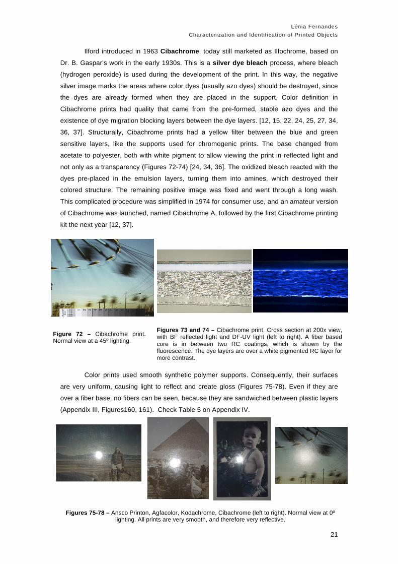
Ilford introduced in 1963 Cibachrome, today still marketed as Ilfochrome, based on
Dr. B. Gaspar’s work in the early 1930s. This is a silver dye bleach process, where bleach
(hydrogen peroxide) is used during the development of the print. In this way, the negative
silver image marks the areas where color dyes (usually azo dyes) should be destroyed, since
the dyes are already formed when they are placed in the support. Color definition in
Cibachrome prints had quality that came from the pre-formed, stable azo dyes and the
existence of dye migration blocking layers between the dye layers. [12, 15, 22, 24, 25, 27, 34,
36, 37]. Structurally, Cibachrome prints had a yellow filter between the blue and green
sensitive layers, like the supports used for chromogenic prints. The base changed from
acetate to polyester, both with white pigment to allow viewing the print in reflected light and
not only as a transparency (Figures 72-74) [24, 34, 36]. The oxidized bleach reacted with the
dyes pre-placed in the emulsion layers, turning them into amines, which destroyed their
colored structure. The remaining positive image was fixed and went through a long wash.
This complicated procedure was simplified in 1974 for consumer use, and an amateur version
of Cibachrome was launched, named Cibachrome A, followed by the first Cibachrome printing
kit the next year [12, 37].
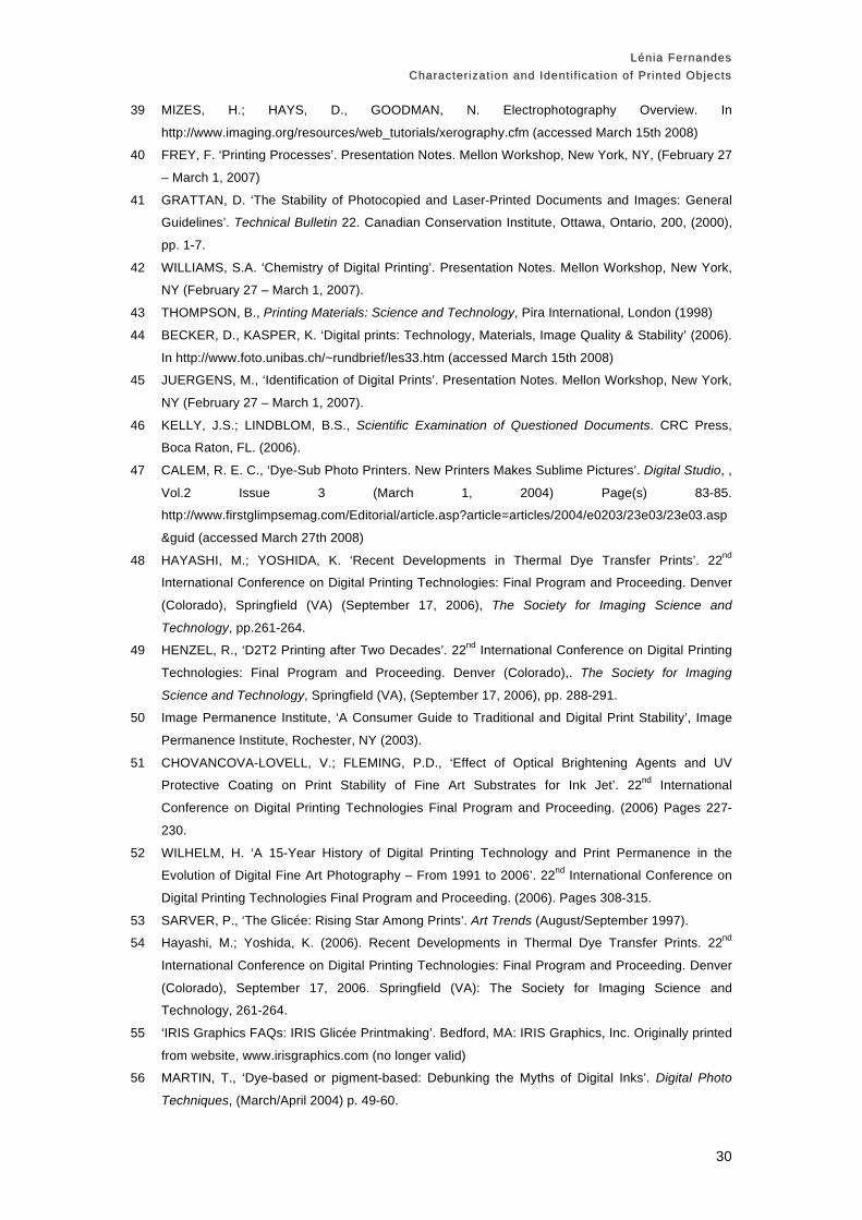
Color prints used smooth synthetic polymer supports. Consequently, their surfaces
are very uniform, causing light to reflect and create gloss (Figures 75-78). Even if they are
over a fiber base, no fibers can be seen, because they are sandwiched between plastic layers
(Appendix III, Figures160, 161). Check Table 5 on Appendix IV.
Figures 73 and 74 – Cibachrome print. Cross section at 200x view, with BF reflected light and DF-UV light (left to right). A fiber based core is in between two RC coatings, which is shown by the fluorescence. The dye layers are over a white pigmented RC layer for more contrast.
Figure 72 – Cibachrome print. Normal view at a 45º lighting.
Figures 75-78 – Ansco Printon, Agfacolor, Kodachrome, Cibachrome (left to right). Normal view at 0º lighting. All prints are very smooth, and therefore very reflective.

Lénia FernandesLénia Fernandes Characterization and Identif ication of Printed ObjectsCharacterization and Identif ication of Printed Objects
22
Digital processes
Digitally created prints diverge from the ones made by conventional photographic processes
because the final print was generally never light sensitive, just like photomechanical prints,
and in addition they are obtained through a digital file, that can be manipulated in a computer,
not by a negative in a transparent support [13].
There are three main digital printing processes: electrophotography, dye transfer and
inkjet. It’s possible for all of us to testify the daily use of these very technology dependent
techniques.
Electrophotography, the process through which photocopies are made, was
invented in 1938 by Chester Carlson, and was widely adopted in the 1960s. At first it was only
black & white, but in 1973 Xerox released the first color printer. It later evolved with the use of
laser and digital printers in the 1980s. Copies made through these methods tend to be done
in glossy clay coated paper, or in ordinary uncoated paper (Figures 81, 86) [39-41].
The technological principle in which electrophotography is based implies the use of
materials with opposite charge. Their charge is changed by a corona, according to the part of
the printing phase. A metallic surfaced cylinder inside the copier receives light communicated
electronically. This light changes the charge of the cylinder, and in these areas a latent image
is formed, attracting toner particles with an opposite charge. Toner consists of a waxy
medium with pigment, charge control agents (CCAs), and in an organic solvent, if they are
used in liquid form. To transfer the image into paper, the electrical charge in the cylinder is
reversed, so that now there’s only attraction between the toner and the support [22, 40-44].
The paper holding the toner goes through a fusing cylinder to ensure the adhesion
between the support and the dry toner, while liquid toner just needs to dry for the print to be
finished. If the print is done in color, this process will have to be repeated for every color in
sequence (cyan, yellow, magenta and black), and the image will be constructed, just like off-
set, with a rosette pattern (Figures 83, 85) [39, 40, 43, 44].
Consequently, dry toner tends to be on a surface level rather than penetrating the
paper support, and has more of a dusty quality related to the pigment particles being on the
surface, unlike the more defined dots composed of liquid toner. Because the pigment is on
the paper surface, the print shows differential gloss. (Figures 83, 84). The liquid toner print
shown in this case is coated, so the pigment doesn’t spread through the paper fibers, but
maintains the same level of gloss as an uncoated paper. Coating exists in both sides since
copiers allow using both sides of the sheet (Figures 85, 86) [40, 45].

Lénia FernandesLénia Fernandes Characterization and Identif ication of Printed ObjectsCharacterization and Identif ication of Printed Objects
23
Figure 79 – B&W electrophotographic print. Normal view at 45º lighting.
Figure 80 – B&W electrophotographic print. 50x view at 90º lighting. The dusty quality of the print can be seen.
Figure 81 – B&W electrophotographic print. Cross-section at 200x view at BF reflected light. The dried toner is deposited on the surface of the print, and is not absorbed by the fibers. This can lead to the separation of the two layers.
Figure 82 – Color dry toner electrophotographic print. Normal view at 45º lighting. The targets used for other digital prints have the same appearance under this lighting.
Figures 83 and 84 – Color dry toner electrophotographic print. 50x view at 45º and 0º lighting (left to right). The dots have a dusty look on a normal viewing angle. Differential gloss is very evident in this case.
Figure 85 – Color liquid toner electrophotographic print. 50x view at 45º lighting. The liquid toner created dots with defined color edges. This sample shows also the rosetta pattern on the bottom area.
Figure 86 – Color liquid toner electrophotographic print. Cross-section at 200x, with BF reflected light.

Lénia FernandesLénia Fernandes Characterization and Identif ication of Printed ObjectsCharacterization and Identif ication of Printed Objects
24
Dye sublimation or thermal transfer dye diffusion (D2T2) is a printing process that
evolved from the dye transfer (D1T1) and the dye thermal transfer (D1T2) processes.
Although the process is called sublimation (passage from solid state to vapor), this physical
change doesn’t actually occur. Nöel De Plasse originally laid out the basis for these
processes in 1947 but it was only in the 1980s that the first dye diffusion printer was made.
The first photo quality printer of this type was Kodak’s XL 7700, released in 1989. Since then,
this process has been used in kiosk and desktop printers, to print images for identification
cards, labels and signs [39, 40, 46-50].
To make an image through this process, inside the printer is a color ribbon, with heat
resisting dyes in a wax medium, in separate areas for yellow, magenta, cyan and black, and
also a finishing layer for protection against UV light and handling (Appendix II, Figure 147). It
is heated preferentially according to the areas where an array of resistors, connected to a
computer. The heat levels of each resistor can vary from between zero and 256, in relation to
the RGB numbers of each pixel that compose the image in the digital file. The support is held
in a cylinder, to turn for every new line that is printed. Combining different colored dots and
changing the ink density in the individual dot creates a truly continuous image. Dots tend to
merge with each other, and the only pattern that can be seen is this type of print comes from
the array of resistors printing a line at a time (Figure 88). [42-45].
Support used for photographs can have white pigmented RC coatings, so the print
has a glossy look (Figure 87, 89), inclosing a paper support. On top, a polymer receiving layer
traps the diffused dyes. Right under it, there’s a voided layer, composed of special polymers
designed especially to avoid heat loss in the process (Figure 89) [49, 50].
Figure 87 – D2T2 print. Normal view at 0º lighting. Because it is an RC coated sample, the surface is smooth and can reflect light easily.
Figure 88 – D2T2 print. 50x view at 45º lighting.
Figure 89 – D2T2 print. Cross-section at 200x, BF reflected light. The layer between the white pigmented RC coating and the top dye layer is the voided layer.

Lénia FernandesLénia Fernandes Characterization and Identif ication of Printed ObjectsCharacterization and Identif ication of Printed Objects
25
The most widely known digital printing process is inkjet. It was first introduced to the
fine art world with the glicée or Iris print in 1989. Technological advanced allowed for the
creation of more precise images, and by 1994 Epson released what was considered the first
inkjet photorealistic printer. Concerns with the permanence of the used water based inks and
their color range have also led to great development of the field. [40, 42, 46, 51-53]
There are two main types of inkjet, both using inks based on the CMYK system:
continuous and drop-on-demand (D.O.D.). In the continuous process, where there’s a stream
of droplets that may or may not be used in the final print, as there’s a magnetic field that
deviates the unwanted droplets into a gutter, where they can be later retrieved by the
machine (Appendix II, Figure 48). Iris prints were made with this system, and when made in
color, have a rosette pattern composed of round dots (Figure 119) [40, 43-45, 55].
The most common type of printers used D.O.D. technology. In this case, the ink is
only turned into a droplet if the computer sends a signal that the drop is needed in a particular
area. The combination of different color drops forms the image. Depending on the system
used, the inks may be water or wax based [40, 43, 44].
The paper supports used for inkjet are chosen according to the desired final effect.
Uncoated papers (usually matte) (Figure 90) were the first type used. Since ink droplets are
absorbed by the paper fibers and the print loses definition, other surfaces were introduced,
combining different paperweights, with RC coatings and receiving layers (Figures 93-100). An
evolution towards coated layers led to two different papers with different receiving layers.
Porous surfaces are typically used for pigment-based inks, and are the most common type of
support for inkjet prints. These surfaces have a layer of inorganic particles (amorphous
alumina or silica) with cavities that trap the pigment (Figures 93, 95-97). Swellable supports
have a top layer composed of an organic polymer that swells as it receives the liquid ink, and
as it dries keeps the ink inside (Figures 94, 98-100) [42, 45, 50, 56].
Please go to Table 6 on Appendix IV.
Figures 90 and 91 – Iris print. 50x view at 45º and 90º lighting (left to right). The ink droplets aren’t well defined because the paper has no coating, showing all the paper fibers.
Figure 92 – Iris print. Cross-section at 200x, with BF reflected light. The ink is absorbed by the top fibers. Also, this paper support is relatively thick.

Lénia FernandesLénia Fernandes Characterization and Identif ication of Printed ObjectsCharacterization and Identif ication of Printed Objects
26
Figure 95 – Inkjet print (pigment) on porous support. 50x view at 45º and lighting. The surface is covered by random inkjet droplets.
Figures 96 and 97 – Inkjet print (pigment) on a porous support. Cross-section at 200x with BF reflected light and DF-UV light (left to right). The fluorescence in this support is related with the polymer used as the cavities for the pigment to be held in.
Figures 99 and 100 – Inkjet print (dye) on a swellable support. Cross-section at 200x with BF reflected light and DF-UV light (left to right). The RC backing and front layer cause this fluorescence.
Figure 98 – Inkjet print (dye) on swellable support. 50x view at 45º and lighting. Ink droplets can be seen without seaming too random.
Figures 93 and 94 – Inkjet prints. Pigment based ink on a porous support and dye based ink on a swellable support (left to right). Normal view at 0º lighting. The irregular surface of the porous support doesn’t reflect much light, but the
opposite happens with the swellable support, that has a smooth surface.

Lénia FernandesLénia Fernandes Characterization and Identif ication of Printed ObjectsCharacterization and Identif ication of Printed Objects
27
CONCLUSIONS
This is, as many other areas of conservation, a subject that demands knowledge from many
different branches: technology, history, both organic and inorganic chemistry, physics and
material science. It’s not a closed subject; it needs to feed from complementary knowledge.
It’s no wonder then that a history book about this subject will have at least a small description
of the materials used for a particular print, and how they were prepared, and a technological
book is likely to reference historical milestones in the evolution of the same process. There
are different focuses, but the common purpose to increase knowledge about prints.
Although there are many more accurate, objective methods through which print
identification and characterization can be made, such as FTIR to distinguish collodion and
gelatin P.O.P. prints through their functional groups, or the XRF explain if the color of a print
is more influenced by the gold or the platinum used in its toning bath, it’s also true that most
those analytical methods aren’t available to everyone that wants to understand prints in a
deeper level. It’s necessary to consider that for most purposes, a simplified approach is more
practical and has more use for the ordinary conservator, working in a museum with a low
budget for technical equipment. A trained eye, accompanied by a hand loupe and a
stereomicroscope, relatively common tool in conservation labs is, can many times be enough.
Even when a conclusion isn’t reached, it is usually good enough of an answer to understand
the main characteristics, deterioration problems and appropriate preservation conditions for a
determined print.
Most of the aspects of print technology have already been studied, and literature can
be found with great detail on the subject. However, when first learning about a specific
subject, an overview is always needed first. The depth of knowledge in the technology field
that a conservator really needs is not as vast as the technician making the prints, but needs
to be thought of, just like there’s knowledge in how medieval paintings were made. Before the
19th century many objects were made without the use of machinery, which doesn’t happen
nowadays. The loss of machines implies the loss of the knowledge of how a particular print
was made. Most people can still grind a pigment, but very few or none can build up a factory
to understand the complex chemistry and producing stages of something like an Ansco
Printon print. And why would you want to do try to repeat it? To understand it, to feel how
difficult it really was to create that, to create a new appreciation for knowledge that human
kind has built up in yet another area, to add value to the resulting prints you’re looking at.
All the processes studied allow creating reproductions. But are reproductions all
exactly the same? They are supposed to be, but subtle differences can usually be seen with a
microscope. In a general sense, it seems that the easier it is to make a reproduction, the less
value it will have. It is ”less unique”, it becomes cheaper to make and to buy. It’s not by
chance that buying a fine-art inkjet photograph won’t have the same market value as a B&W
silver gelatin print. Still, the work behind creating the matrix to obtain all these reproductions,
whether it’s based on manipulating software in a computer or perfecting edges of a metal

Lénia FernandesLénia Fernandes Characterization and Identif ication of Printed ObjectsCharacterization and Identif ication of Printed Objects
28
plate, may be of great extent, so the print maintains its value because they are diverse and
unique in their own way.
Differentiating between photomechanical and photographic prints can immediately
separate stable, pigment based images from silver images, usually more sensitive to light and
humidity conditions. Separating color photographs from digital prints can be particularly
difficult because there are also traditional color photographs being printed digitally.
Documenting surface qualities of prints digitally demands more equipment than just
its identification and characterization, but still, standardizing lighting techniques and software
may be useful, for example when for comparing prints that are not geographically close. In
the case of www.digitalsamplebook.org, it acts as a reference point for print identification. The
evolution towards www.graphicsatlas.org will make these images even more powerful,
specially when it concerns to passing down the knowledge acquired about images through
images [2].
ACKNOLEDGMENTS
I would like to thank: James Reilly, Ryan Boatright, Gawain Weaver, Zach Long, Patricia Ford
and everyone else at IPI, for their acceptance and continuous support; Prof. Dr. José
Sanches Ramos from FBA-UL; Prof. Dr. Pires de Matos and Ana Maria Martins from FCT-
UNL; the help of Luisa Casella and Catarina Mateus; my supportive family and patient
friends.
REFERENCES
1 GASCOIGNE, B., How to identify prints, 2nd ed., Thames & Hudson, New York (2004).
2 http://www.digitalsamplebook.org (accessed October 10th 2007)
3 http://www.imagepermanenceinstitute.org (accessed October 10th 2007) 4 REILLY, J.M., Care and Identification of 19th Century Photographic Prints, 3rd ed., Eastman Kodak
Company, Rochester (2001).
5 HUNTER, D., Papermaking. The History and Technique of an Ancient Craft. Dover Publications,
Inc. , New York (1978)
6 CASEY, J.P., Pulp and Paper. Chemistry and Chemical Technology. 2nd ed., Volume II,
Interscience Publishers, New York (1960).
7 EICHENBERG, F., The Art of the Print, Harry N. Abrams, Inc., New York Publishers (1976).
8 http://www.moma.org/exhibitions/2001/whatisaprint/flash.html (accessed November 27th 2007) 9 PANKOW, D., Tempting the pallete. A survey of color printing processes. 2nd ed., RIT Cary
Graphic Arts Press, Rochester (NY), 2005.
10 HIND, A.M., A history of Engraving and Etching from the 15th century to the year 1914, Dover
Publications, USA (1963).
11 MERTLE, J.S.; MONSEN, G.L., Photomechanics and Printing. Mertle Publishing Company,
Chicago (1957).
12 PAVÃO, L., Conservação de Colecções de Fotografia. Dinalivro, Lisboa (1997).

Lénia FernandesLénia Fernandes Characterization and Identif ication of Printed ObjectsCharacterization and Identif ication of Printed Objects
29
13 PERES, M.R. The Focal Encyclopedia of Photography, 4rd ed, Focal Press, USA (2007).
14 NADEAU, L., Encyclopedia of Printing, Photographic and Photomechanical Processes. Vols.1 and
2.: Atelier Luis Nadeau, Canada (1989).
15 EVANS, R.M.; HANSON Jr., W.T., BREWER, W.L. Principles of Color Photography, John Wiley &
Sons, Inc., New York (1953).
16 SIPLEY, L.W., Photography’s Great Inventors, American Museum of Photography, Philadelphia
(1965).
17 CRAWFORD, W., The Keepers of Light. Morris & Morris Dobbs Ferry, NY. (1979).
18 EDER, J.M., History of Photography, Dover Publications, Inc., New York (1978).
19 ABNEY, W.W, A Treatise on Photography. Longmans, Green and Co., London (1881).
20 OLIVER, B., A History of the Woodburytype, 1st ed., Carl Mautz Publishing, Nevada City (CA)
(2007).
21 WOOD, H.T. Modern Methods of Illustrating Books. A.C. Armstrong, New York (1887)
22 SIPLEY, L.W., A Half Century of Color. MacMillan Company, New York (1951).
23 REYDEN, D., ‘History, technology, and treatment of specialty papers found in archives, libraries
and museus: tracing and pigment-coated papers.’, in
www.si.edu/mci/downloads/RELACT/coat_special_papers.pdf (accessed February 15th 2008) 24 COOTE, J.H., Colour Prints, 4th ed., Focal Press Ltd, Great Britain (1972).
25 COOTE, J.H., The Illustrated History of Colour Photography, Fountain Press, Great Britain: (1993).
26 KEPPLER, V., The Eighth Art, 1st ed., William Morrow & Co, New York (1938).
27 COE, B., Colour Photography, 1st ed, Ash & Grant Ltd, London (1978).
28 CARTIER-BRESSON, A., Les Papiers Sales, Direction des Affaires Culturelles de la Ville de Paris
/ Paris Audiovisuel, Paris (1984).
29 REILLY, J.M., ‘The Manufacture and Use of Albumen Paper’, The Journal of Photographic
Science, Vol. 26, (1978). pp. 156-61, in http://albumen.stanford.edu/library/c20/reilly1978.html
(accessed October 13th 2007)
30 WENTZEL, F., Memoirs of a Photochemist. American Museum of Photography. Philadelphia
(1960). 31 REILLY, J.M., ‘The History, Technique and Structure of Albumen Prints’. AIC Preprints. (May
1980). pp.93-98., in http://albumen.stanford.edu/library/c20/reilly1980.html (accessed October 13th
2007)
32 REILLY, J.M., The Albumen and Salted Paper Book: The History and Practice of Photographic
Printing 1840-1895, 1st ed., Light Impressions, Rochester (1980).
33 PENICHON, S., ‘Differences in image tonality produced by different toning protocols for matte
collodion photographs’. Journal of the American Institute for Conservation, Vol. 38, No. 2
(Summer, 1999), pp. 124-143.
34 KRAUSE, P.; SHULL, H.A. Complete Guide to Cibachrome Printing, HP Books, Tucson (1982).
35 BAGBY, R., Anscochrome and Ektachrome Home Processing, 9th ed., Amphoto, New York (1972).
36 WILHELM, H., BROWER, C. The Permanence and Care of Color Photographs, Preservation
Publishing Company, Iowa. (1993).
37 COOTE, J.H., The Focalguide to Cibachrome, Focal Press, Great Britain (1978).
38 NADEAU, L. ‘Office Copying & Printing Processes’, in Guide to the Identification of Prints and
Photographs, in http://palimpsest.stanford.edu/byauth/nadeau/copyingprocesses.pdf (accessed
March 22nd 2008)
Lénia FernandesLénia Fernandes Characterization and Identif ication of Printed ObjectsCharacterization and Identif ication of Printed Objects
30
39 MIZES, H.; HAYS, D., GOODMAN, N. Electrophotography Overview. In
http://www.imaging.org/resources/web_tutorials/xerography.cfm (accessed March 15th 2008)
40 FREY, F. ‘Printing Processes’. Presentation Notes. Mellon Workshop, New York, NY, (February 27
– March 1, 2007)
41 GRATTAN, D. ‘The Stability of Photocopied and Laser-Printed Documents and Images: General
Guidelines’. Technical Bulletin 22. Canadian Conservation Institute, Ottawa, Ontario, 200, (2000),
pp. 1-7.
42 WILLIAMS, S.A. ‘Chemistry of Digital Printing’. Presentation Notes. Mellon Workshop, New York,
NY (February 27 – March 1, 2007).
43 THOMPSON, B., Printing Materials: Science and Technology, Pira International, London (1998)
44 BECKER, D., KASPER, K. ‘Digital prints: Technology, Materials, Image Quality & Stability’ (2006).
In http://www.foto.unibas.ch/~rundbrief/les33.htm (accessed March 15th 2008)
45 JUERGENS, M., ‘Identification of Digital Prints’. Presentation Notes. Mellon Workshop, New York,
NY (February 27 – March 1, 2007).
46 KELLY, J.S.; LINDBLOM, B.S., Scientific Examination of Questioned Documents. CRC Press,
Boca Raton, FL. (2006).
47 CALEM, R. E. C., ‘Dye-Sub Photo Printers. New Printers Makes Sublime Pictures’. Digital Studio, ,
Vol.2 Issue 3 (March 1, 2004) Page(s) 83-85.
http://www.firstglimpsemag.com/Editorial/article.asp?article=articles/2004/e0203/23e03/23e03.asp
&guid (accessed March 27th 2008)
48 HAYASHI, M.; YOSHIDA, K. ‘Recent Developments in Thermal Dye Transfer Prints’. 22nd
International Conference on Digital Printing Technologies: Final Program and Proceeding. Denver
(Colorado), Springfield (VA) (September 17, 2006), The Society for Imaging Science and
Technology, pp.261-264.
49 HENZEL, R., ‘D2T2 Printing after Two Decades’. 22nd International Conference on Digital Printing
Technologies: Final Program and Proceeding. Denver (Colorado),. The Society for Imaging
Science and Technology, Springfield (VA), (September 17, 2006), pp. 288-291.
50 Image Permanence Institute, ‘A Consumer Guide to Traditional and Digital Print Stability’, Image
Permanence Institute, Rochester, NY (2003).
51 CHOVANCOVA-LOVELL, V.; FLEMING, P.D., ‘Effect of Optical Brightening Agents and UV
Protective Coating on Print Stability of Fine Art Substrates for Ink Jet’. 22nd International
Conference on Digital Printing Technologies Final Program and Proceeding. (2006) Pages 227-
230.
52 WILHELM, H. ‘A 15-Year History of Digital Printing Technology and Print Permanence in the
Evolution of Digital Fine Art Photography – From 1991 to 2006’. 22nd International Conference on
Digital Printing Technologies Final Program and Proceeding. (2006). Pages 308-315.
53 SARVER, P., ‘The Glicée: Rising Star Among Prints’. Art Trends (August/September 1997).
54 Hayashi, M.; Yoshida, K. (2006). Recent Developments in Thermal Dye Transfer Prints. 22nd
International Conference on Digital Printing Technologies: Final Program and Proceeding. Denver
(Colorado), September 17, 2006. Springfield (VA): The Society for Imaging Science and
Technology, 261-264.
55 ‘IRIS Graphics FAQs: IRIS Glicée Printmaking’. Bedford, MA: IRIS Graphics, Inc. Originally printed
from website, www.irisgraphics.com (no longer valid)
56 MARTIN, T., ‘Dye-based or pigment-based: Debunking the Myths of Digital Inks’. Digital Photo
Techniques, (March/April 2004) p. 49-60.

Lénia FernandesLénia Fernandes Characterization and Identif ication of Printed ObjectsCharacterization and Identif ication of Printed Objects
31
57 WACHOWIAK, Jr., M.J., Microscopy of Protective & Decorative Coatings. Course Manual. 3-5
June, Suitland, Maryland, Smithsonian Center for Materials Research and Education (revised
2002).
58 Copying, (7th ed., first 1969 printing), Eastman Kodak Company, Rochester (NY) (1969).
59 CROY, O.R., Camera Copying and Reproduction (2nd. Ed.). Focal Press Ltd., London (1966).
60 ABRAMOWITZ, M., DAVIDSON, M. W., ‘The Concept of Magnification, in
’http://www.olympusmicro.com/primer/anatomy/magnification.html (accessed November 5th 2007)
61 SAWYER, L.C., GRUBB, D.T., “Specimen Preparation methods”, in Polymer Microscopy (2nd ed.),
Chapman & Hall, New York, (1996).
62 GRAY, P., (ed.), Encyclopedia of Microscopy & Microtechnique, Ed. Van Nostrand, New York City
(NY), (1973).
63 VERRI, G., et al. “Post-capture data analysis as an aid to the interpretation of ultraviolet-induced
fluorescence images”, in SPIEIS& T/ Vol. 6810 6810021
64 http://www.inchem.org/ (accessed April 25th 2008)
65 http://hyperphysics.phy-astr.gsu.edu/Hbase/Tables/indrf.html (accessed April 25th 2008)
66 Print identification workshops by James Reilly, Ryan Boatright and Gawain Weaver, held at IPI for
the Advanced Residency Program Fellow (George Eastman House), in 10/12/2007; 10/27/2007;
12/14/2007; 01/25/2008; 05/01/2008; 05/14/2008.
All images © Image Permanence Institute, by Ryan Boatright and Zach Long.

Lénia FernandesLénia Fernandes Characterization and Identif ication of Printed ObjectsCharacterization and Identif ication of Printed Objects
32
APPENDIX I: Experimental
The main characteristics depicted on the imaging techniques described here are
summarized in Appendix IV, Table 7.
Camera and system calibration
All the imaging is done with the Canon EOS 5 digital SLR camera, with 12.8 MP
resolution. The lens used in the copy stand is the Canon Macro EF 100mm. For the shots
done with the Olympus AX70 compound microscope, this lens is taken out. The camera is
attached to the microscope it with an adaptor, so it captures the image directly from the
objective lens.
Images are captured in the raw file format, extension .cr2 (Canon’s format), in which
it is already a digital negative. Theoretically, this makes possible for the image to be retrieved
in the original conditions in which it was taken. Digital imaging is in this case very appropriate
since the images are used in the web [57].
The imaging system needs to be calibrated so that the obtained images are accurate
in relation to reality, and with each other. The computer monitor is calibrated with an Eye-One
Photo SG, and the obtained images are also calibrated with the RAGS system. The RAGS
calibration is first done photographing a 24-patch GretagMacBeth ColorChecker (Figure 101),
and with the Adobe Photoshop software, creating a set of characteristics in a digital camera
profile, to make it look as accurate as possible. These characteristics are saved in the
calibration file, and are then applied to all the image files obtained with the same lighting
angle and magnification as the target.
After the image file is calibrated, it is saved in the .dng (digital negative) format, the
extension that Adobe applies to the raw file. This allows returning to the original parameters
the file was made in, since it has an XMP metadata file that is always attached to it.
.
Figure 101 - 24-patch GretagMacBeth ColorChecker. In http://www.xrite.com/product_overview.aspx?ID=685&Action=support&SupportID=3308 (accessed
December 11th 2007)

Lénia FernandesLénia Fernandes Characterization and Identif ication of Printed ObjectsCharacterization and Identif ication of Printed Objects
33
Copystand
The vertical copystand holds the prints horizontally, in parallel with the camera attached
to the column, making it easier to avoid key stoning and other distortions. Light sources are
usually mounted in the copystand, and additional lights in the room are shut down. The prints
are placed over a perforated surface that is attached to a vacuum. This avoids light
interferences by flattening the print, and keeps the print in the right position for shooting. The
background is usually black, to avoid more reflections, and is usually edited out later on
Adobe Photoshop [58].
The 45º reflected light (normal lighting) shot is used to capture an image of the
complete object, therefore the distance from the object to the camera can vary (Figure 102).
Right now, on www.digitalsamplebook.org, the imaging has been done all at the same
distance of the print, at 76,2 cm, but bigger prints are photographed with the lens further away
or it will only part of the image will be captured [2].
The copystand has four strobes (flash lights with 120 v, 21w, and 5900ºK), 2 in each
side of the camera, being held by the copy stand arms, pointed at the print in a 45º angle
(Figures 102, 103). This position eliminates interference from textured supports and surface
gloss and avoids having less light on the corners of image [58]. Using flashlights instead of
tungsten continuous lights eliminated the problem of over heating the print’s surface, and no
special filters are needed to calibrate the image due to the light source. The back wall next to
the copystand is painted black to eliminate unwanted reflections.
The acquiring conditions are F22 aperture, sensitivity ISO 100, and 5900ºK
temperature (to match the lights used). The shutter speed is adjusted. The shot is made with
the Stouffer Graphic Arts R1215 grayscale (Figure 104). This view is used to see the image
subject, tone, contrast and apparent sharpness. The examples shown that were captured in
this way are Figures 1, 3, 5, 8, 16, 18, 20, 23, 25, 27, 29, 36, 39, 42, 48, 51, 54, 58, 63, 66,
69, 72, 79, 82, 105, 106 and 157.
The same can be done for back view, specially if there are any stamps, inscriptions or
other information on the back of the support, or just to see what the base tint is. The back
view isn’t used in www.digitalsamplebook.org, but it is an important for documentation view
(Figures 105, 106) [2].
Figure 102 – Copystand setup for 45º lighting used at IPI.
Figure 103 – Standard 45º lighting setup scheme. Light comes from both sides at a 45º angle (a), and is captured by the camera (b). Adapted from http://www.kodak.com/global/en/consumer/products/techInfo/am100/am100.shtml (accessed June 15th 2008)
90º 45º
a a
b

Lénia FernandesLénia Fernandes Characterization and Identif ication of Printed ObjectsCharacterization and Identif ication of Printed Objects
34
Figure 104 – Stouffer Graphic Arts R1215 grayscale. This scale has twelve different shades of grey. In http://www.stouffer.net/graphics/12.jpg (accessed December 15th 2008)
Figures 107 and 108 – Collodion P.O.P. and matte collodion prints (left to right). 45º view in the macro shot. In these images it is possible to observe image structure (both images are continuous tone), the
image tone (the collodion print has a warm dark drown color and the matte collodion has a cooler, dark green tone). Image definition is another detected feature.
Figures 105 and 106 – Albumen print in the carte de visite format, at 45º lighting. This example from the IPI collection, not on www.digitalsamplebook.com, is shown to demonstrate an example in with the back of the print has information, in this case from the studio in which the print was made.

Lénia FernandesLénia Fernandes Characterization and Identif ication of Printed ObjectsCharacterization and Identif ication of Printed Objects
35
At a 41,2 cm distance, for macro photography in 45º light, the conditions are changed
to F2.8 aperture, ISO 100, and 3100ºK temperature, adjusting the exposure time according to
the print. The images captured in this view can be useful for showing patterns or details
(Figures 107, 108). This technique was used to create the images shown in Figures 4, 6, 9,
21, 107, 108 and 156.
A 45º UV light shot can be made in a different copystand, with 2 mercury lamps placed
at a 45º angle from the print. However, this view has yet to be included in
www.digitalsamplebook.org. There have been discussions about ways to cut down the visible
light part of the spectrum of the light sources, to ensure that there’s no interference from
apparent fluorescence. This is preferable to using filters in the camera lens or to treat the
image with software after the image has been acquired. Also, another issue is what kind of
scale can be used as reference for UV light, in order to calibrate the image properly [2, 63].
The axial shots (0º lighting) are made using a fiber-optic light source that faces a half-
silvered mirror. The mirror is placed at a 45º from the print and the camera lens, that is 20”
(51 cm) from the print (Figures 109, 110). The image is captured with an F8 aperture, ISO
100, 3100ºK temperature and 1/2 s acquiring time. Specular reflection is greater on smooth
surfaces, because light is less scattered, like in glossy collodion P.O.P. surfaces (Figure 43).
On rougher or textured surfaces (with matting agents or supports without coatings or with
applied textures) light will have more interferences, so it will be more likely to diffuse more
uniformly, like in matte collodion prints (Figure 48). There are a particular group of prints that
might show differential gloss (low and high density areas reflect light in distinct ways), caused
by having the image forming material in a higher relief that the support, like
electrophotography and Woodburytypes (Figures 21, 22; Figure 83, 84). Images captured
using this technique can be found in Figures 43, 49, 52, 75-78, 87, 151-153 and 158.
Macro photography is also done in this view, at the same distance used for 45º light.
This view is useful for detecting how gloss is shown by the surface, including differential gloss
(Figures 111, 112). This magnification was used in Figures 22, 93, 94, 111 and 112.
Figure 109 – Copystand for the axial light shot, showing the mirror and the fiber optic cable.
Figure 110 – Standard 0º lighting set up scheme. The light comes from the fiber optics (a), is scattered upon the print’s surface by reflection from the silver mirror (b) and its interaction is captured by the camera (c).
45º
90º a
b
c

Lénia FernandesLénia Fernandes Characterization and Identif ication of Printed ObjectsCharacterization and Identif ication of Printed Objects
36
Many times, the surface upon the print is made has texture, a quality that is suppressed
by 45º lighting, since the purpose of this type of lighting is to eliminate all the shadows from
the paper surface [59]. To study the effect of textures in printed surfaces, a fiber optic line is
placed in the side of the print, at a 90º angle (Figures 113, 114). This creates a racking light
effect, that casts shadows caused by presence of texture, or has no effect if the surface is
perfectly smooth (Figures 115, 117). The line light is placed close to the edge of the print, in
the same planar level as the base of the copystand. The camera uses the 100mm lens, and
has a bellows style adjustable lens hood placed in front of it to ensure that the camera
records the light effect coming front the print’s surface and as little stray light as possible. The
angle of the lighting may cause the surface to cast unwanted shadows, if it is wrinkled or in
for some reason no longer flat [59].
Images are acquired with ISO 100 and F/8 aperture. The shutter speed is adjusted to
minimize clipping (loss of image information in Dmax and Dmin areas).
In macrophotography the effect of texture on the surface will be noticed (Figures 116,
118). An examples taken in raking light is shown in Figure 7.
I
Figures 111 and 112 – Collodion P.O.P. and matte collodion prints (left to right) at the macro shot, at 0º lighting. Because the surface is so smooth on the collodion P.O.P. sample, light is reflected almost entirely, and the silver image is barely seen. The opposite happens with the matte collodion print.
Figure 113 – Copystand setup for the racking light shot. The fiber optics cable is on the bottom left side.
Figure 114 - Standard 90º lighting set up scheme. The light comes from the fiber optic line (a), and the camera captures the light. A bellows is used.
90º a
b

Lénia FernandesLénia Fernandes Characterization and Identif ication of Printed ObjectsCharacterization and Identif ication of Printed Objects
37
Photomicrography
Microscope
Microscopic techniques have long been used in the conservation field as a common tool for
understanding the structure of objects by exploring views and properties that the human eye
can’t detect by itself [57].
The Olympus AX70 compound microscope is used in similar ways to what is done
in the copystand, using a low and a high magnification, with the camera placed over it in a
platform (Figure 119). For observation, the eyepieces need to be adjusted for every viewer.
For documenting the images obtained, the 5x optical lens is used for surface shots and the
20x for a higher magnification shot on racking light and to view cross sections, where the
morphology of the sample can be analyzed. Since the eyepieces are 10x, the standard for
microscopes, when using the 5x, the total visual magnification is 50x, and with the 20x the
total is 200x [60].
Figures 115 and 116 – Collodion P.O.P. print. Normal and macro shot at 90º lighting (left to right). This smooth surface doesn’t show texture in either of the images.
Figures 117 and 118 – Matte collodion print Normal and macro shot at 90º lighting (left to right). The texture of the paper support can be seen in the normal shot, and further detected on the macro shot.
Figure 119 – Olympus AX70 compound microscope with digital camera attachment.

Lénia FernandesLénia Fernandes Characterization and Identif ication of Printed ObjectsCharacterization and Identif ication of Printed Objects
38
To simulate 45º reflected light on the microscope, the light path is polarized and the
microscope is set to bright field (BF) (Figure 120). A tungsten light source is used to emulate
daylight conditions [57]. This lighting and magnification were used in 2, 17, 24, 26, 28, 30,
37, 40, 55, 59, 83, 85, 88, 90, 95 and 98.
To simulate axial lighting, BF is used without using the polarizers, which makes the
light source come down into the print directly, therefore creating the 0º effect. This type of
lighting is used in 5x magnification and also for the 20x. With the higher magnification matting
agents and other surface characteristics can be depicted (Figure 121). This is done in higher
density areas of the print, so that more contrast is obtained in the final image. Acquiring
conditions are ISO 100, 3300ºK temperature. The aperture value (F) isn’t specified, since the
camera lens isn’t used (just the objective in the microscope) and exposure time is defined for
every print. Figures 56, 60 and 84 were captured in this way.
Because the magnification is higher, it is more difficult to obtain good depth of field for
imaging, especially when relatively large particles are in the print’s surface. To solve this
problem, a few shots are made of the same sample (usually between two and six), varying 5
µm of distance between the sample’s surface and the optical lens. The RAW images are
processed in Adobe Photoshop, to adjust their contrast, brightness and saturation levels.
They are then saved in the .tif file format, so they can be transferred into Image Pro Express
software. This software allows composing the files into one single image, in the Extend Depth
of Field option, combining all the focused areas of each file (Figures 122, 123).
Figure 120 – Scheme for bright field lighting in the microscope. In http://www.olympusmicro.com/primer/anatomy/reflectkohler.html (accessed May 20th 2008)
Figure 121 – Matte collodion print at 50x magnification, seen under non polarized BF (simulating 0º lighting). The surface has many irregularities for the light to interfere with.
Figures 122 and 123 – B&W silver gelatin print form a 1937 Kodak Sample Book, named Kodak Royal Bromide Grade T. Left: regular image, with out of focus bottom left corner; Right: composite image, all focused. Non polarized BF, at 200x. Not on www.digitalsamplebook.com.

Lénia FernandesLénia Fernandes Characterization and Identif ication of Printed ObjectsCharacterization and Identif ication of Printed Objects
39
This makes the imaging technique more subjective, because it has to go through
more processing steps, but at the same time objectivity has to be slightly sacrificed for
understandability.
Racking light shots in the microscope are obtained by using an exterior small fiber
optics light line, and capturing the image seen through the 5x objective (50x of total
magnification). The acquiring conditions are ISO 100, and as in normal and
macrophotography, the shutter speed varies.
This view shows paper fibers in paper supports that have none or little baryta layer.
The images shown in Figures 10-13, 31-33, 44, 50, 57, 80, 91 and 159-161 were captured
through this technique.
Cross sections are made so that the side of the paper can also be explored. It is a
way of understanding the relationship of all the components of the print [57]. In the Microtome
section it will be explained how the samples are prepared.
They are viewed in 20x magnification. Since samples are very thin, almost
transparent, they can be observed with polarized BF transmitted light [61]. Depending on the
sample, it is possible to see paper fibers or polyester support, the baryta layer, the ink or
emulsion layers, matting agents, and relative thickness of every layer and the overall print.
Cross-sections of this type are shown in Figures 14, 15, 34, 38, 41, 45, 47, 53, 61, 62, 64,
67, 70, 73, 81, 86, 89, 92, 96 and 99.
In dark field (DF) reflected UV light is used, obtained from a mercury arc lamp. It is
possible with this lighting to identify materials sensitive to this radiation through the
fluorescence shown by mostly of organic substances, such as resin-coated papers
(polyester), optical brightening agents (OBAs) (in silver B&W papers) and some dyes (Figure
124). When using this light, no filters are used in the microscope. The calibration of the image
is done subjectively, comparing what is seen in the microscope and the image obtained in the
monitor, since there’s interference from visible light [57, 62, 63]. UV light was used in Figures
35, 46, 65, 68, 71, 74, 97, 100, 124, 149 and 150.
Figure 124 – Gelatin P.O.P. print under UV lighting. DF Reflected light at 200x. The top gelatin layer shows some fluorescence, while the remaining layers of the print (baryta layer and the paper support)
don’t show the same phenomenon.

Lénia FernandesLénia Fernandes Characterization and Identif ication of Printed ObjectsCharacterization and Identif ication of Printed Objects
40
Microtome
To view the print’s stratigraphy, a sample with about 10x2 mm has to be taken with a cutting
knife, meaning that the sample will be visibly affected by the procedure. It shouldn’t be done
in valuable samples where esthetics are a factor (Figures 125-126). It’s usually taken in areas
where there’s contrast between low and high-density areas, so that in cross-section they can
be distinguished, and represent the surface. If there’s an area with these characteristics along
the edges of the print, it is the preferred place to take a sample from here.
To create serial sections (instead of imbedding the sample) a customized Microm HM
355 S micrometer is used (Figure 127). The sample is attached to a horizontal stand and the
blade arm moves, as opposed to the normal micrometer. Ideally, the samples should have
regular cross sections, so it will be focused under the microscope. To do so, a sharp blade at
0º inclination is used and the same area isn’t used twice to ensure the best performance.
Small samples are made different thickness, usually between 20 to 30 µm. Under this value,
they tend to become too thin and detach the different layers. When they are too thick, they
tend to flip and stay parallel to the lens, and what is observed is the surface of the print and
not the section. [57].
The samples are collected with a dental pick and placed in microscopic slide that is
then toped with a cover slip (Figure 128). White spirit is used as a medium, due to its
refractive index (1.41-1.44) being closer to glass (1.52) than water (1.33), therefore allowing a
more accurate visualization of the sample because there is less light interference [64, 65].
The plate is placed in the microscope’s stage to be observed at 20x magnification
(Figure 129). If needed, the stage is rotated to correct the positioning of the sample, so it can
be photographed properly. The image placed in www.digitalsamplebook.org is the sample
that shows best the print’s structure and has better definition [2, 57].
Figures 125 and 126 – Cutting a sample for cross sectioning.
Figure 127 – Microm HM 355 S micrometer.

Lénia FernandesLénia Fernandes Characterization and Identif ication of Printed ObjectsCharacterization and Identif ication of Printed Objects
41
Stereomicroscope
The Olympus SZH-ILLD model has been used for print observation and identification, with
magnification raging from 7.5x up to 64x (Figure 130).
This tool allows viewing the prints in their real color, a very important characteristic for
identification. The image is also viewed in the correct special orientation, facilitating its use.
As the microscope, the eyepieces have to be adjusted for individual observation for better
understanding of the samples and a more comfortable use [4, 57]
A fiber optic line is used as a light source, and its intensity and relative position is
adjusted to the observed sample and the desired effect, and it is used in reflected light
(Figure 131). The characteristics depicted with the light at 45º and 90º are the same as the
ones seen in the microscope, ranging from seeing paper fibers, surface texture, etc.
Figure 128 – Collecting sample with dental pick.
Figure 129 – Placing the glass slide under the microscope for observation of the cross sections.
Figure 130 – Olympus SZH-ILLD stereoscope.
Figure 131 – Print observation under the stereoscope. In this case, the fiber optics are positioned in a close to 45º, to observe image structure of the print.

Lénia FernandesLénia Fernandes Characterization and Identif ication of Printed ObjectsCharacterization and Identif ication of Printed Objects
42
APPENDIX II: Print technology illustrations
Figure 132 – Pre-photographic processes: relief (ink on the plate’s surface), intaglio (ink inside the plate’s grooves) and planographic (ink across the printing surface, where it’s not repelled by water). Adapted from Hayter.
Light exposure Negative Dichromated gelatin Plate
Warm water to remove unsensitized gelatin Dichromated gelatin Plate
Figure 133 – The first two steps for using dichromated gelatin in photomechanical processes. A negative transparency is used, and the positive image in the gelatin hardens. The remaining is washed of, leaving a gelatin mould.
Heat Expanded dichromated gelatin Plate
Fast cooling Reticulated dichromated gelatin Plate
Ink Reticulated dichromated gelatin Plate
Figure 134 – Production of a collotype. After the steps depicted in Figure 162, the plate goes into an oven. This expands the gelatin. Is it cooled so it retracts and reticulates. The ink can be spread across the surface, and acquires the
reticulation pattern.

Lénia FernandesLénia Fernandes Characterization and Identif ication of Printed ObjectsCharacterization and Identif ication of Printed Objects
43
Press Lead sheet Dichromated gelatin Plate
Lead sheet Pigmented gelatin
Figure 135 – Woodburytype technology. The dichromated gelatin, sensitized as shown in Figures 163 and 164, is used to create a relief mold on a lead sheet, using a press. Pigmented gelatin, not sensitive to light, will be placed in this
mould to be printed on paper. Adapted from Oliver, p. 112.
Figure 136 – Production of photogravures. Initially, a positive transparency is used over a resin dust covered metal plate. The gelatin that didn’t harden is taken away with water. An acid bath will etch these areas, while the positive image is being protected by the hardened gelatin, taken away previously to printing. The resin is taken away, revealing the unetched metal surface. The ink resides inside the etched grooves.
Light exposure Positive Dichromated gelatin Resin dust Metal plate
Warm water Dichromated gelatin Resin dust Metal plate
Acid Dichromated gelatin Resin dust Metal plate
Ink Metal plate

Lénia FernandesLénia Fernandes Characterization and Identif ication of Printed ObjectsCharacterization and Identif ication of Printed Objects
44
Figure 137 – Making rotogravures. The dichromated gelatin is pre-sensitized to pick up the cross-line screen pattern. After that, a positive is used under light, so the gelatin records a negative image. After being washed, the dichromated gelatin is transferred into a metal cylinder, so it is etched. The ink settles inside the etched
pits, from where it will be transferred to a paper surface.
Light exposure Cross-line screen Dichromated gelatin Peel-off sheet
Light exposure Positive Dichromated gelatin Peel-off sheet
Warm water Dichromated gelatin Peel-off sheet
Acid Dichromated gelatin Metal cylinder
Ink Metal cylinder

Lénia FernandesLénia Fernandes Characterization and Identif ication of Printed ObjectsCharacterization and Identif ication of Printed Objects
45
Figure 138 – Printing with a rotogravure press. The doctor blade takes the excess ink off of the cylinder, and is then transferred onto the paper surface with a pattern. In Crawford, p. 238.
Light exposure Negative captured with a cross-line screen Dichromated gelatin Peel-off sheet
Warm water Dichromated gelatin Peel-off sheet
Acid Dichromated gelatin Metal plate/cylinder
Ink Metal plate/cylinder
Figure 139 – Making letterpress halftone prints. A negative captured with a cross-line screen is used. After using acid to etch the plate, the gelatin is removed from it and the ink placed on the relief areas of the plate.

Lénia FernandesLénia Fernandes Characterization and Identif ication of Printed ObjectsCharacterization and Identif ication of Printed Objects
46
Figure 140 – Change in halftone patterns according to the percentage of area covered by the dots. In middle tone areas (between 40 and 60% of ink), the image presents a checkered pattern. In between 10%-
30% and 70%-90% the image will show a dotted pattern. In Mertle, p. 95.
Light exposure Negative captured with a cross-line screen Dichromated gelatin Lithographic plate
Warm water Dichromated gelatin Lithographic plate
Water Dichromated gelatin Lithographic plate
Ink / Water Dichromated gelatin Lithographic plate
Figure 141 – Making an offset print. After the dichromated gelatin is sensitized, the remaining part is washed off with warm water. These areas are again covered with a water solution. Then, the hardened gelatin is taken off, and the plate is covered with greasy ink. It will only adhere in these areas because they were
protected against water so the ink won’t be repelled.

Lénia FernandesLénia Fernandes Characterization and Identif ication of Printed ObjectsCharacterization and Identif ication of Printed Objects
47
Figure 142 –Off-set printing. The original image is positive, being inverted when it is transferred to the blanket roller. The final print will have a positive image. In Hawken, p. 202.
Figure 143 – The carbon process. A gelatin tissue is contact printed with a negative. The tissue is placed on a temporary support, where it is washed to remove the soft gelatin. The hardened gelatin relief is transferred to the final support. In Coe, 97.
Figure 144– The carbro process. It is distinguished from the carbon process because the negative is printed on B&W silver bromide paper, and this bromide is squeeged against carbon tissue. The bleaching of the silver image will provoque selective hardening of the tissue. It is then placed on a temporary support, washed and the relief image is transferred to the final support. In Coe, 98.

Lénia FernandesLénia Fernandes Characterization and Identif ication of Printed ObjectsCharacterization and Identif ication of Printed Objects
48
Figure 146 – Processing of the original Kodachrome film. After light exposure, the film goes through B&W development, producing a negative silver image in each of the emulsion layers. A bleaching step is required to remove the silver and the yellow filter. This is followed by color development, done selectively for each layer, starting with the cyan, and finalizing with the yellow layer. In Coote, Illust.
Figure 145 – Processing for Ansco Printon. The print first goes through B&W development to expose all the silver in the emulsion layers. Redevelopment (with a color developer) will lead to the formation of metallic silver and dyes. A bleaching bath removes all the metallic silver, leaving behind only the dyed image. The combination of the cyan, magenta and yellow layers will reproduce the colors of the original subject. The same principle applies to Agfacolor prints. In Sipley, Half Century.

Lénia FernandesLénia Fernandes Characterization and Identif ication of Printed ObjectsCharacterization and Identif ication of Printed Objects
49
Figure 50– Scheme for silver dye bleach principle
In coe 131
Figure 148 – Scheme for a continuous ink jet printer. In Thompson, p.463
Figure 147 – Scheme for a D2T2 printer. The support is held on a roller, turning when a different part of the color ribbon is under the thermal heads. Adapted from Thompson, p.470.
Support
Thermal head
Color ribbon

Lénia FernandesLénia Fernandes Characterization and Identif ication of Printed ObjectsCharacterization and Identif ication of Printed Objects
50
APPENDIX III: Other images
Figures 151-153 – Salted paper print, albumen print and glossy albumen cabinet card print (left to right). Normal view at 0º lighting. The cabinet card is not on www.digitalsamplebook.com.
Figure 156 – Hand colored albumen print. Macro view at 45º lighting. not on www.digitalsamplebook.com.
Figures 149 and 150 – Engraving and etching (left to right). Cross sections at 200x, with BF reflected light and DF-UV light. The paper fibers show no fluorescence.
Figures 154 and 155 – Matte albumen print. Normal view at 45º and 0º lighting (left to right).

Lénia FernandesLénia Fernandes Characterization and Identif ication of Printed ObjectsCharacterization and Identif ication of Printed Objects
51
Figures 157-158 – Platinum print. Normal view at 45º and 0º lighting (left to right).
Figure 159 – Platinum print. 50x view at 90º lighting.
Figures 160-161 – Agfacolor, Cibachrome (left to right). 50x view at 90º lighting. Using a plastic coating over a paper base core prevents the print’s surface from showing irregularities related to those
fibers.

Lénia FernandesLénia Fernandes Characterization and Identif ication of Printed ObjectsCharacterization and Identif ication of Printed Objects
52
APPENDIX IV: Tables
The following five tables have the goal of summing up all the described information
and also to refer some processes that weren’t described in the main part of this paper
(cyanotype, platinotype) and help in their identification. This information has been based on
references used in main text and also information gathered in workshops attended at IPI. The
tables can be used as a reference guide for print identification, however more aspects need
to be referred to, such as the type of support used, its function, subject, size, deterioration,
etc. [1, 2, 4, 8, 9, 12, 17, 24, 25, 36, 42, 45, 46, 66]
There are many different variations of the B&W silver gelatin papers that are not
going to be explained here. However, their identification can be done in relationship with
gelatin P.O.P. prints. B&W prints where introduced in the 1890s, and produced from there on
in many surfaces. The image tone is usually neutral or cold, and the image may show silver
mirroring and yellowing in the highlights due to deterioration. There are also sulfur toned
papers, common between 1910 and 1950 in portraits, that show little or none image
deterioration [12].
The last table is adapted from one used for reference of IPI’s staff, synthesizing the
qualities of each imaging technique as able to depict the main characteristics looked for in
each print.

53
Characteristics Main production dates
Image structure Image Relief
Differential gloss
Visible paper fibers
Image material Support Image Deterioration
Other features
Collotype 1855-1960s Reticulation pattern • Oil + pigment (ink) Paper Woodburytype 1865-1900s Continuous tone
image; Pigment particles
• • On non image areas
Pigment + gelatin Paper Cracks on dark image
areas
Prints under 20x25 cm Pigment particles
Cropped around the edges
Photogravure 1879-early 20th century
Aquatint grain • Oil + pigment (ink) Paper Plate mark
Rotogravure 1895-1970s White line grid with small, same size,
inked squares
• Oil + pigment (ink) Paper In dark areas the squares might not be
seen Letterpress halftone
1890s-1950s Halftone pattern with squeeze-out
• Oil + pigment (ink) Paper Merging squares on dark areas, round dots
on highlights Offset lithograph
1910-today Halftone pattern without squeeze-out
• Oil + pigment (ink) Paper Rosetta pattern; FM pattern (same size
dots, different frequency)
Dots: squares (up to the 1950s), elliptical
(after 1950s)
Characteristics Main production dates
Image structure Surface gloss
Differential gloss
Visible paper fibers
Image material
Support Image Deterioration
Other features
Woodcut Early 14th-19th
century Dark image areas with sharp edges
• Oil + pigment
(ink)
Rag paper
Engraving Mid 15th-18th century
Lines or dots • Oil + pigment
(ink)
Rag paper
Plate mark
Etching Late 15th - 18th century
Lines or dots, gradation
• • • Oil + pigment
(ink)
Rag paper
Plate mark
Lithograph Late 18th - late 19th century
Tone gradation • Oil + pigment
(ink)
Rag paper
Surface has a waxy feel
Table 1 – Summary of the characteristics of pré-photographic prints.
Table 2 – Summary of the characteristics of photomechanical prints.

54
Characteristics Main production dates
Image structure Image tone Color in toned images
Surface gloss
Visible paper fibers
Image Material
Support Image Deterioration Other features
Salted paper 1840s-1860s Continuous tone image
Warm Dark brown/Purple
• Silver Paper Loss of highlights, change in image tone
Thin, mounted
Albumen mid 1850s-1900s
Continuous tone image
Warm Dark brown/Purple
• • Silver + Albumen
Paper Loss of highlights, change in image tone, cracking of the binder, silver mirroring;
overall yellowing; fading due to presence of metallic
particles
Common on cartes de visite
Thin, mounted prints. Unmounted: tendency to
curl
Matte albumen 1890s-1910s Continuous tone image
Warm Dark brown/Purple
• Silver + Albumen
Paper Loss of image highlights, change in image tone
Grey or black cardboard mounts
Collodion P.O.P.
1870s-1900s Continuous tone image
Warm Dark brown/Purple
• Silver + collodion
Baryta paper
Iridescence Loss of image highlights
Silver Mirroring
Soluble in acetone Common on cabinet
card Tinted support
Burnishing marks in the back of the support
Matte collodion P.O.P.
1890s-1910s Continuous tone image
Cold Blackish dark green
• Silver + collodion
Baryta Paper
Fine image detail; Image transfer to other
supports because of platinum
Gelatin P.O.P. 1880s-1910s Continuous tone image
Warm Dark brown/Purple
• Silver + gelatin
Baryta Paper
Silver mirroring Loss of image highlights,
Common on cabinet card
Tinted support
Table 3 – Summary of the characteristics of printing-out process prints.

55
Characteristics Main production dates
Image structure Surface gloss
Differential gloss
Visible paper fibers
Image material Support Image Deterioration
Other features
Carbon
1865-1910s Continuous tone image
• • On non image areas
Pigment + Dichromated gelatin
Baryta paper
Pigment particles Cracks on dark image
areas Fine image detail
Carbro Early 20th century - 1950s
Continuous tone image
• • Pigment + Dichromated gelatin
Baryta paper
Pigment particles; used for color images;
missregistration of layers Less mage detail due to
image enlargement Platinotype 1880s-1930s Continuous
neutral tone image
• Iron salts Paper Yellow circles around images
formed by platinum
Fine image detail; Positive image transfer to other supports because of
platinum
Cyanotype 1870s-1950s Continuous blue tone image
• Iron salts Paper Loss of contrast if exposed to
light or alkaline environments
Table 4 – Summary of the characteristics non-silver processes prints.

56
Characteristics Main production dates
Image structure Surface gloss
Visible paper fibers
Image material Support Image Deterioration Other features
Ansco Printon
Mid 1940s-1973 Continuous tone image
• Dyes + gelatin Paper, acetate, Dye fading (hue shift); overall yellowing due to
deterioration of non used dye couplers
Minicolor and Kotavachrome formats
Agfacolor Mid 1940s-1990s
Continuous tone image
• Dyes + gelatin Paper, acetate, RC coated
Dye fading (hue shift); overall yellowing due to
deterioration of non used dye couplers
White borders
Kodachrome 1935-1970s Continuous tone image
• Dyes + gelatin Acetate, RC coated White borders
Cibachrome 1963-1990s Continuous tone image
• Azo dyes + gelatin
Acetate, RC coated and polyester
Colors with metallic reflex; deep, dark blacks;
saturated colors
Characteristics Main production dates
Image structure Surface gloss
Differential gloss
Visible paper fibers
Image material
Support Image Deterioration Other features
Electrophotography
1960s-today Dots • • • Toner Paper Dry toner detaches from support (flacking)
Dry toner – dusty dots, loose particles Liquid toner – dots with defined edges;
Rosetta pattern; AM dots (same
frequency, different size dots)
Dye sublimation Early 1980s - today
Continuous tone image
• Dyes + waxy medium
Any type, with plastic overcoats
Parallel lines across surface from printing
Inkjet Late 1980s - today
Ink droplets • Pigment /dyes + water + organic solvents
Any type (uncoated,
porous, swellable,
etc.)
Dye based – dissolved in contact with water (ink bleeding); sensitive to
ozone Pigment based – easily
abraded Dye fading (Hue shift)
Continuous – dots are evenly spaced, in
a line formation D.O.D. – dots don’t
show pattern
Table 5 – Summary of the characteristics of color photography prints.
Table 6 – Summary of the characteristics of digital prints.

57
View
Characteristics Im
age
Mar
king
s an
d in
scrip
tions
Imag
e C
ontr
ast
Imag
e sh
arpn
ess
Imag
e to
ne
Bas
e tin
t
Fluo
resc
ence
Text
ure
Pape
r fib
ers
Glo
ss
Mat
ting
agen
ts
Normal recto Image color and content, base color, markings and inscriptions
• • • • •
Normal verso Paper tint, markings and inscriptions • • Macro Sharpness of image •
45º (normal)
Micro (50x) Sharpness of image • Normal recto Overall texture and planarity • Macro Pattern of texture and presence of
paper fibers • •
90º (racking) Micro (50x) Visibility of paper fibers and structure
of texture • •
Normal recto Degree of gloss • Macro Interaction of gloss and surface
microtexture •
Micro (50x) Presence of matting agents • 0º (axial)
Micro (200x) Structure, size and density of matting agents
•
Normal (200x) Layer structure, support thickness • Cross-sections UV light (200x) Fluorescence of components • • Primary view for characterization • Secondary view for characterization
Table 7 – Summary of the characteristics seen in each imaging technique.