characterization of a digital radiography system marine torrollion tutor: j-m dalin dut physics...
TRANSCRIPT
Characterization of a digital radiography
system
Marine Torrollion
Tutor: J-M DALINDUT Physics measures internship to 04/04/11 from
17/06/11
EN/MME/MM departement
1

1. The radiographic non-destructive tests at CERN1.1. The radiography laboratory1.2. The material used
2. Description of the digital radiography system2.1. Steps of the radiography acquisition2.2. List of the parameters2.3. Quality of the picture
3. System characterization3.1. Study of the X-Ray beam3.2. Creation of control graphics
Conclusion 2

1. The radiographic non destructive tests at CERN
3Photography of the radiography lab

1.1. The radiography laboratory
A control area : the bunker
Radiography instruments are stored in a closed room with concrete and lead walls and roof:- two X-ray tubes- the X-ray tomograph
Its role at CERN• Perform the control of metallic
pieces
• Material defects, scattered porosity, cracks…
• Accept or reject with respect to reference quality levels
4Photography of the big door of the bunker Examples of weld defects

1.2. Materials usedOrdinary films Phosphor platesSilver films
-single use, price : €8.30 each
-non linear response
-have to be developed with a complex and heavy process which needs chemical products
Cover of phosphor crystals
-can be used 1000 times, possibility to delete the picture in memory, price : €300/unit
-linear response
- can be read directly with a scanner, easy to stock and to be networkaccessible
- are easier to recycle
5
Phosphor plates
Silver films

Phosphor plates
Scanner DURR
X-ray Tube PhillipsComputer
6

2.1. Steps for the radiography acquisition
7
Connection with a USB cable

2.2. List of the parameters
Plate in leadPhosphor plate
Piece containing weld
xX-Ray tubeX-Ray tube
Collimator
ADJUSTABLE PARAMETERSAnode
x * F : distance piece- source
F
* b : distance piece - plate
b * e : piece thickness
e
Potential difference ddp
I
cathode
* ddp : potential difference
* I : size of the source
* T : Time of exposureT
FIX PARAMETRERS
* µ : linear coefficient of attenuation (cm-1) 8

2.3. Quality of the picture
Homogeneity of the radiations
Resolution
Linearity of the absorption
1 mm
IQIs classicals Target with convergent lines
Homogenous plate of aluminum
Graduates wedges
9
X-ray
Low intensity High intensity

3. System characterization
10

3.1. Study of the X-ray beamObjective : To measure the influence of the piece-source distance on the beam diameter and the radiation intensity.
11

The influence of the piece-source distance on the beam diameter
Incertitudes of repetability = corrected standard deviation of the measures
- Function is a straight line: diameter = f(f)
- The diameter grows proportionally with the piece-source distance
- Possibility to check the angle of irradiation with trigonometric calculations12

Comparison of slopes for irradiations angles of 35 and 40 degrees
- The three experimental measures are on the theoretical straight line of
α = 40°
- The provider announces an irradiation angle of 35°
- The outline of the beam is blur13
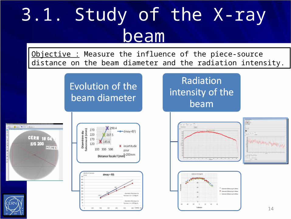
3.1. Study of the X-ray beamObjective : Measure the influence of the piece-source distance on the beam diameter and the radiation intensity.
14
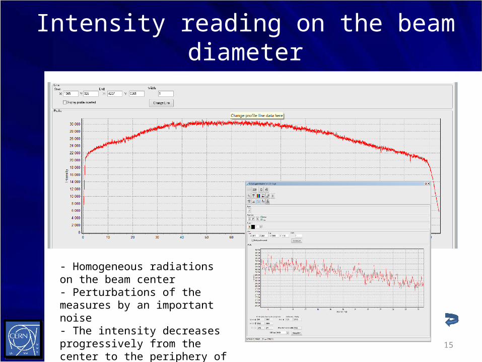
Intensity reading on the beam diameter
- Homogeneous radiations on the beam center- Perturbations of the measures by an important noise- The intensity decreases progressively from the center to the periphery of the beam 15

Intensity handreading on beam’s diameters
- Radiation distribution is similar in the three cases
- Only the intensity changes with the piece-source distance
- 40 % of the beam is homogeneous
16

3.2. Creation of control graphics
Radiography series
N° radio
T (s) ddp (kV)
f (mm) pictures
1 45 60 450
2 70 60 450
3 45 70 450
4 45 70 600
17
Objective : To allow the operator to achieve a good result at the first manipulation and gain time

Example of a graphic obtained with a copper wedge , f = 450 mm :
18

Final presentation of the controls graphic
Controls graphic for copper piece and a piece-source distance of 450 mm at 10 mA
19

Conclusion
• Scientific assessment: This work allowed me to check the distribution of the beam radiation, and to create the control graphics for a source of 10 mAThe control graphics allow the operators to obtain a good radiography at a first manipulation.
• Follow-up actions: The creation of control graphics for 4 mA source and a study of the image quality (resolution, contrast, brightness, ...).
20

Thanks
Many thanks to Jean-Michel Dalin, my tutor, for his attention and his explanations, As well as to Mr. Sgobba, in charge of the section EN/MME/MM.
Thanks to Aline Piguiet for her assistance during the manipulations.
And finally, a huge thanks to all the section members.
21

End of the presentation
Thanks for your attention,
Any questions ?
22