characterization of ni, mo and ni–mo catalysts supported
TRANSCRIPT
Ž .Journal of Molecular Catalysis A: Chemical 145 1999 169–181www.elsevier.comrlocatermolcata
Characterization of Ni, Mo and Ni–Mo catalysts supported onalumina-pillared a-zirconium phosphate and reactivity for the
thiophene HDS reaction
J. Merida-Robles, E. Rodrıguez-Castellon, A. Jimenez-Lopez )´ ´ ´ ´ ´Departamento de Quımica Inorganica, Cristalografıa y Mineralogıa, Facultad de Ciencias, UniÕersidad de Malaga, 29071 Malaga, Spain´ ´ ´ ´ ´ ´
Received 19 May 1998; accepted 19 November 1998
Abstract
A series of fluorinated alumina pillared a-zirconium phosphate supported with nickel, molybdenum and nickel–molybdenum sulfide catalysts was prepared in order to investigate the use of an alumina-pillared material, i.e., an aluminadiluted within another inorganic matrix, as a support of sulfide catalysts. The catalysts were prepared by impregnation, withloadings of 4, 8, 12 wt.% of Ni; 13 wt.% of Mo and 2.1–9, 3–13 wt.% of Ni–Mo followed by calcination at 673 K.
Ž .Sulfidation was performed at 673 K for 2 h. They were characterised by X-ray diffraction XRD , temperature-programmedŽ . Ž .reduction TPR and X-ray photoelectron spectroscopy XPS . The set of data indicated that in the Ni-based catalysts a
fraction of the loaded Ni2q interacts with the support and cannot be sulfided at 673 K. However, a total sulfidation of Ni2q
Ž .is reached in the NiMo-based catalysts. The Ni 2p binding energy B.E of Ni–Mo sulfided catalysts shifted to higher3r2Ž .values )1 eV with respect to those observed in Ni-based catalysts suggesting the existence of different environments for
Ž .Ni in these materials. The catalysts can be easily regenerated by treatment with 5% vrv O rN mixture at 673 K without2 2
noticeable loss of activity. The catalysts exhibited a high activity and stability for thiophene HDS particularly the NiMocatalysts due to the promotion of Ni for Mo-based catalysts. q 1999 Elsevier Science B.V. All rights reserved.
Keywords: Pillared; Alumina; Nickel; Molybdenum; HDS; Catalysis; Zirconium phosphate
1. Introduction
Hydrodesulfurization is one of the most im-portant reactions in petroleum refining pro-cesses for removing sulfur components in thefeedstock. These components present several
) Corresponding author
important problems such as pollution of theenvironment through increased SO emissions,2
corrosion of materials with which they havecontact, poisoning of reforming catalysts, andcause petroleum products to have undesirableodors and burning characteristics. In recentyears, growing environmental concerns havecoupled with dwindling fossil fuel reserves toincrease the interest in HDS catalysts for pro-
1381-1169r99r$ - see front matter q 1999 Elsevier Science B.V. All rights reserved.Ž .PII: S1381-1169 99 00048-5

( )J. Merida-Robles et al.rJournal of Molecular Catalysis A: Chemical 145 1999 169–181´170
ducing cleaner fuels from lower quality feed-stocks.
Among the numerous catalytic formulae in-vestigated, the most commonly used are CoMoand NiMo mixed sulfides supported on alumina.
w xThe results of intensive research 1–11 showthat in the final oxidic or precursor state variousdegrees of chemical interaction exist betweenthe amorphous alumina and the transition metaloxides. Some of the formed phases are verystable and resist sulfidation. Studies on nickelsulfide catalysts have concluded that supports,such as Al O , interact strongly with Ni2q
2 3
cations which impede their sulfidation. X-rayŽ .photoelectron spectroscopy XPS and X-ray
Ž .diffraction XRD revealed the presence of thephase NiAl O on catalysts, which is formed on2 4
w xcalcination at high temperatures 12–15 .Metal–alumina interactions may be weak-
ened by using carriers such as alumina-pillaredcompounds, where the aluminium oxide is di-luted within a layered inorganic matrix. In thesesystems, alumina nanoparticles induce perma-nent porosity by propping open the layers of thehost, thus making the resulting solids suitable tobe used as supports. In this way Occelli and
w xRennard 16 applied a pillared bentonite as asupport for an Ni–Mo catalyst for hydrogena-tion-hydrocracking of vacuum gasoil feed-
w xstocks, and Kloprogge et al. 17 supportednickel sulfide on alumina pillared montmoril-lonite which exhibits high activity for DHS ofthiophene. In previous works, we described thepreparation and surface properties of fluorinated
w xalumina a-zirconium phosphate materials 18as well as their use as supports for preparingnickel catalysts. These catalysts proved to behighly active for the hydrogenation of benzene
w xwith imperceptible deactivation 19 . The aim ofthe present work was thus to study the effect ofthese pillared structures on sulfidation and activ-ity of supported-nickel, molybdenum andnickel–molybdenum sulfide catalysts for theHDS reaction. For this purpose, the materialswere characterized using XRD, XPS, thermo-
Ž .programmed reduction TPR with H and, fi-2
nally, the hydrodesulfurization of thiophene hasbeen chosen to probe the activity of these differ-ent supported catalysts.
2. Experimental
The support chosen was a fluorinated alu-mina pillared a-zirconium phosphate, prepared
w xas described elsewhere 18 and calcined at 673K for 6 h. The calcined material, with empirical
w Ž . xfo rm ulae : Z r A l O O H F3.39 1 .12 1 .60 4 .90Ž . 2qH PO , hereafter referred as AlZrP-1. Ni0.57 4 2
and MoŽVI. were incorporated into the supportsusing the incipient impregnation method with
Ž .ethyl alcohol solutions of Ni NO correspond-3 2
ing to nickel loadings of 4, 8 and 12 wt.% andaqueous solutions of ammonium molybdatewŽ . xNH Mo O P4H O corresponding to 134 6 7 24 2
wt.%. Another set of catalysts containing bothnickel and molybdenum were prepared by suc-cessive impregnations with loadings of 2.1–9wt.% and 3–13 wt.% Ni–Mo. All samples werethen dried at 333 K and calcined at 673 K for 5h.
The TPR of thermally treated samples wasperformed between 313 and 973 K, using a flow
Ž 3 .of ArrH 40 cm rmin, 10% of H and heat-2 2
ing at 10 Krmin. The water produced in thereduction was eliminated by passing the gas
Ž .flow through a cold finger 193 K . The con-sumption of reductor was controlled by an on-line gas chromatrograph provided with a TCdetector.
Ž .Powder diffraction patterns XRD of sam-ples were performed with a Siemens D501diffractometer, provided with a graphite mono-chromator and using Cu Ka radiation. XPSanalysis were obtained with a Physical Electron-ics 5700 instrument with a Mg Ka X-ray exci-
Ž .tation source hns1253.6 eV and hemispheri-Ž .cal electron analyser. Accurate "0.1 eV
Ž .binding energies BEs were determined withrespect to the position of the C 1s peak at 284.8eV. Mol percentages of P, O, Zr, Ni, Mo and Swere determined. The measured peaks areas
( )J. Merida-Robles et al.rJournal of Molecular Catalysis A: Chemical 145 1999 169–181´ 171
Ž .P 2p, O 1s, Zr 2p, Ni 2p, Mo 3d and S 2pŽ y1.counts s of the fits were multiplied with the
w xcorresponding sensitivity factors 20 . The resid-ual pressure in the analysis chamber was main-tained below 10y9 Torr during data acquisition.The catalysts were always handled under hex-ane after the sulfidation to keep them underair-free conditions.
The catalysts were tested in the thiophenehydrodesulfurization reaction at 673 K, using anautomatic microcatalytic flow reactor under at-mospheric pressure. The catalysts were sup-ported between quartz wool in a quartz tubereactor; the catalyst charge used was 0.2 g
Žwithout dilution. The catalysts were heated 673.K under He flow and then sulfided in situ in a
3 Ž .flow of 60 cm rmin H SrH 10% H S us-2 2 2
ing the following temperature programme: 10Krmin increase from r.t. to 673 K and keepingthe catalysts for 1 h at 673 K. After sulfidation,the gas flow was switched to the reaction mix-ture; a hydrogen flow of 50 cm3rmin contain-ing 4.0 mol.% thiophene. The contact time was0.15 g srmmol and catalysts did not showdiffusion restrictions. The reactor effluents weresampled via a microvolume sampling valve andinjected into a gas chromatogragh equipped witha flame ionization detector and a capillary col-
Ž .umn TRB-1 . Based on conversion data, andassuming that reactions are pseudo-first order,
Ž .reaction rate constants K and K wereHDS HYD
calculated.
3. Results
3.1. Characteristics of the support and calcinedprecursor samples
A fluorinated alumina pillared a-zirconiumphosphate support designated as AlZrP-1Ž 2 .Al O , 29.3 wt.%; S s184 m rg was used2 3 BET
in this study. This material displays a mixedporosity, essentially within the range of meso-porous but with a micropore contribution of
3 Žf0.1 cm rg, and containing acid sites 1.5mmol NH rg determined by NH thermal pro-3 3
.grammed desorption , mainly of Lewis type,which are active in the dehydration of isopropyl
w xalcohol 18 .Calcination of precursor samples at 673 K
gave rise to the formation of Ni, Mo and Ni–Mooxides supported on the pillared materials. Thepresence of NiO and MoO on the surface of3
the supports was confirmed by XRD and XPSanalysis. The characteristic diffraction lines of
˚NiO appear at 2.41, 2.09 and 1.48 A for the
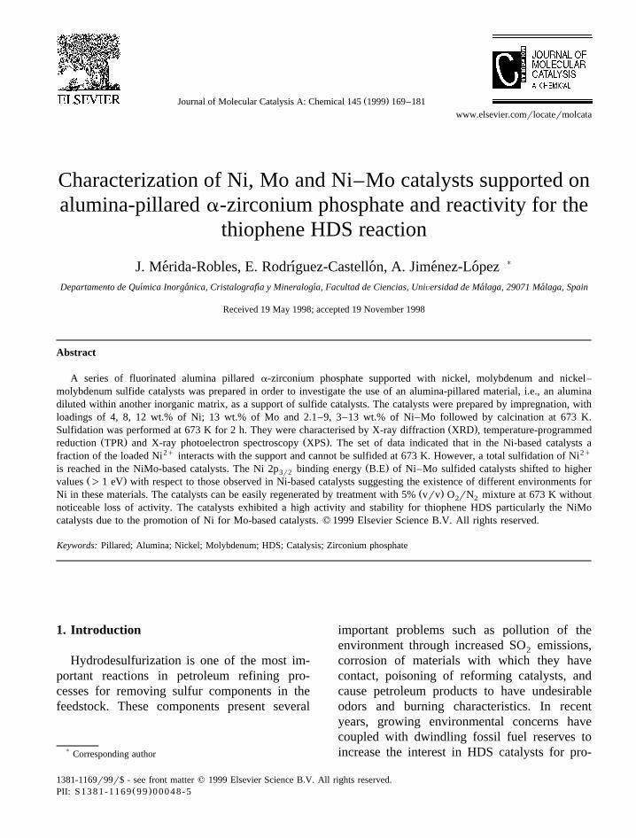
Fig. 1. TPR profiles of NiO supported materials with different NiŽ . Ž . Ž . Ž . Ž . Ž .percentages wt.% : a 0%; b 4%; c 8%; d 12%; e 12%
Ž . Ž .623 K ; f unsupported NiO.

( )J. Merida-Robles et al.rJournal of Molecular Catalysis A: Chemical 145 1999 169–181´172
Fig. 2. TPR profiles of NiMo and Mo oxides supported materials:Ž . Ž . Ž . Ž .a Ni–Mo 2.1–9%; b Ni–Mo 3–13%; c Mo 13%; d unsup-ported MoO .3
Ni-based materials, and their intensities in-creased with nickel loading, as expected. TheXRD patterns of samples containing Mo andNi–Mo oxides only show the peaks correspond-
˚ing to MoO at 3.81, 3.46 and 3.26 A. This3
means that Ni2q is highly dispersed in Ni–Moprecursors.
The TPR profiles of NiO supported on alu-mina-pillared a-zirconium phosphate are shownin Fig. 1. The existence of several definedranges of H consumption in the TPR profiles2
pointed to the presence of more than one Ni2q
species in calcined precursors with differentdegrees of metal–support interaction. It is as-sumed that a stronger interaction with the sup-port results in a higher reduction temperature.The samples with maximum loading of Ni andcalcined at the lower temperature of 623 Kappears to be easily reducible with a maximumat 673 K.
Ž .Although the reduction process of Mo VI toŽ .Mo 0 takes place in two steps at 893–925 K
w xand 1075 K 21 , the TPR profiles of Mo andŽ .NiMo calcined precursors Fig. 2 only includeŽ . Ž .the reduction step from Mo VI to Mo IV in as
Ž . Ž .Fig. 3. Ni 2p spectra of NiO supported materials: a 4%; b3r2Ž . Ž . Ž .8%; c 12%; d 12% 623 K .

( )J. Merida-Robles et al.rJournal of Molecular Catalysis A: Chemical 145 1999 169–181´ 173
much as sulfidation of molybdenum oxide usu-ally leads to the formation of MoS . In general,2
the low content of Ni in NiMo materials doesnot seem to affect the reducibility of MoO . In3
contrast to supported nickel oxides, the molyb-denum ones present the reduction peak at atemperature lower than that of the bulk MoO3
and the small difference in temperature is in-dicative of a weak interaction of the molybde-num oxide with the support.
The degree of interaction of the Ni, Mo andNiMo oxides with the support was studied by
Ž .XPS. The Ni 2p XPS spectra Fig. 3 show a3r2
main peak, characteristic of Ni2q, which shiftsto lower BE values from 856.1 to 855.1 eV andbecomes wider at higher nickel loading. In sam-ples with loading higher than 8%, this peakcould be decomposed into two components, onecentered at 854.1 eV and the other at 856.1 eVŽ .Table 1 . Taking into account that the BE forun-supported NiO is 853.5 eV, the peak at854.1 eV may be assigned to Ni2q in octahedralsites of the supported NiO structure, and thepeak at 856.1 eV may then be associated withNi2q in tetrahedral positions of a spinel-likestructure of Ni–Al oxide, created as a result of
Ž .Fig. 4. Ni 2 p spectra of NiMo oxide supported materials: a3r2Ž .Ni–Mo 2.1–9%; b Ni–Mo 3–13%.
the solid-state diffusion of Ni2q into the latticew xduring the calcination process 12,22 . When the
Ž .calcination temperature is lower 623 K , theintensity of the low energy peak increases as aconsequence of the decreased diffusion of Ni2q
Table 1Ž .Binding energy BE , surface atomic ratio as determined by XPS analysis
Ž . Ž . Ž .Ni wt.% Mo wt.% BE eV Atomic ratio on surface
Ni 2p Mo 3d NirZr MorZr SrMo SrNi %Ni3r2 sulfided sulfided
Un-sulfided catalysts4 855.9 0.718 855.7 0.9812 856.1–854.7 1.48
Ž .12 623 K 855.3–853.5 2.032.1 9 855.4 232.6–235.5 0.42 3.433 13 855.5 232.5–235.5 0.96 5.780 13 232.6–235.7 4.01
Sulfided catalysts4 855.7–851.8 0.50 1.06 22.68 855.6–851.5 0.85 1.05 30.612 855.3–851.3 1.01 1.47 34.3
Ž .12 623 K 855.4–852.4 1.49 1.30 33.62.1 9 852.7 229.1–232.3 0.67 2.98 1.94 100.03 13 852.8 229.1–232.3 1.16 3.82 1.98 100.00 13 229.2–232.3 3.01 1.68

( )J. Merida-Robles et al.rJournal of Molecular Catalysis A: Chemical 145 1999 169–181´174
Ž .into the support Fig. 3, curve d . The peaklocated at 862 eV, which essentially remains inthe same position corresponds to the shake-up
2q w xsatellite structure of Ni 23 . The Ni 2p3r2
spectra for the samples containing NiMo oxidesŽ .Fig. 4 show a weak peak with BE valuesabout 855.5 eV, this value is halfway betweenthose found for Ni supported precursors. Thisnew BE value suggests that the environment ofNi2q ions in NiMo materials is different fromthat in supported nickel oxides. The XPS Mo 3d
Ž .spectra Fig. 5 for the samples containing MoO3
and mixed oxides of NiMo show the MoO3
characteristic doublet, Mo 3d and Mo 3d5r2 3r2
with BE values of 232.2 and 235.5 eV, respec-tively. The MorZr surface atomic ratio hasbeen obtained from the XPS superficial analy-sis. This ratio, for samples with the same load-ing of Mo, is higher in the samples whichcontain NiMo than in those having only Mo.This means that the dispersion of MoO is3
higher in materials containing Ni as promoterŽ .atoms Table 1 .
Fig. 5. Mo 3d spectra of Mo and NiMo oxide supported materials:Ž . Ž . Ž .a Mo 13%; b Ni–Mo 2.1–9%; c Ni–Mo 3–13%.
Ž .Fig. 6. Ni 2p spectra of supported Ni sulfide catalysts: a 4%;3r2Ž . Ž . Ž . Ž .b 8%; c 12%; d 12% 623 K .
3.2. Sulfided catalysts
Evidence of formation of metallic sulfides onthe support surface was again provided by XRDand XPS analyses. The XRD patterns of sul-fided Ni–AlZrP catalysts show the presence oflow crystallinity sulfide phases for loadinghigher than 8% with very weak diffraction lines
˚at 1.71, 1.97 and 2.97 A corresponding to NiS.This phase is usually found in catalysts where
w xstrong nickel–support interactions occur 24,25 .Neither phase was detected in 4 wt.% Ni sam-ple, suggesting that, Ni2q should be extremely

( )J. Merida-Robles et al.rJournal of Molecular Catalysis A: Chemical 145 1999 169–181´ 175
Ž .Fig. 7. Ni 2p spectra of supported NiMo sulfide catalysts: a3r2Ž .Ni–Mo 2.1–9%; b Ni–Mo 3–13%.
dispersed in this case also and strongly interact-ing with the support. In the XRD patterns of Moand NiMo catalysts, the diffraction peaks corre-
˚sponding to the MoS phase at 2.03 and 2.35 A2
are hardly visible. Also the absence of diffrac-tion lines of nickel sulfide in the sulfidedNiMo–AlZrP catalysts may indicate that Ni2q
could be inserted into the structure of MoS2
forming a solid solution.The BE values, NirZr and MorZr surface
atomic ratios for samples before and after sulfi-dation are compared in Table 1. Since the BE ofZr 3d and P 2p core electrons were practi-5r2
cally constant with values of 183.3 and 134.1eV, respectively, and the PrZr atomic ratio wasmaintained close to the theoretical value, PrZrs2, it may be inferred that the impregnation–calcination–sulfidation processes did not signif-icantly alter the host framework. The Ni 2p3r2
Ž .XPS spectra of sulfided Ni catalysts Fig. 6show a new peak at 851.3–851.9 eV, which isindicative of the presence of sulfided nickel,together with another signal in the range 855.0–855.7 on the same position that the highest
energy peak in the precursor and assigned to Niin the form of NiAl O . This means that a2 4
fraction of Ni in the oxide form which stronglyinteracts with the support it cannot be sulfidedat 673 K.
The BE of Al 2p core electrons in the precur-sor is close to 74.9 eV and is also shifted to
Ž .higher energy values 75.4 eV in the sulfidedsamples, probably as a consequence of theNi2q-alumina pillar interaction. From XPS data,percentages of Ni2q sulfidation on the inte-grated peak area of nickel sulfide to the entire
Ž .Ni peak area including the satellite peak hasbeen evaluated. By this method, the percentagesof sulfided nickel were lower than 35%. Adecrease in the surface NirZr ratio was ob-served in nickel supported catalysts after sulfi-dation, attributed to the agglomeration of parti-cles forming nickel sulfide. The SrNisulfided
Ž .surface atomic ratios Table 1 point to thepresence of the NiS phase in these catalysts,which is in agreement with the XRD data.
Fig. 8. Mo 3d spectra of supported Mo and NiMo sulfide cata-Ž . Ž . Ž .lysts: a Mo 13%; b Ni–Mo 2.1–9%; c Ni–Mo 3–13%.
( )J. Merida-Robles et al.rJournal of Molecular Catalysis A: Chemical 145 1999 169–181´176
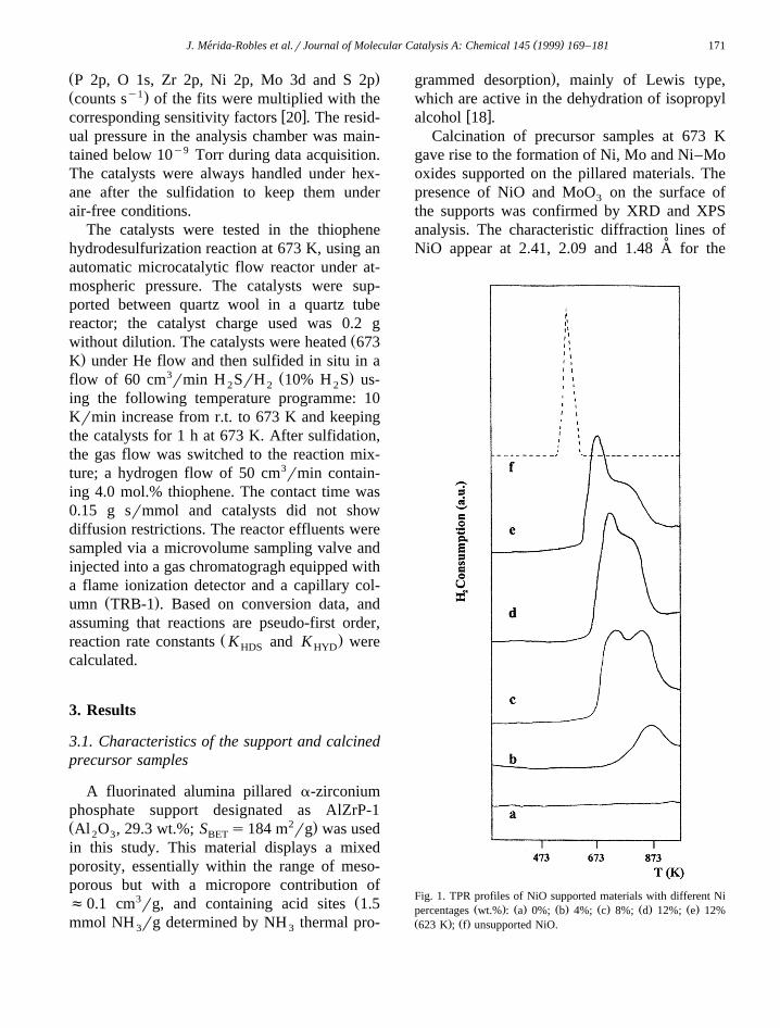
Fig. 9. Plots of K vs. time on-stream for supported Ni, MoHD S
and NiMo sulfide catalysts.
The Ni 2p spectra of sulfided NiMo–Al-3r2Ž .ZrP catalysts Fig. 7 show a single signal at ca.
Ž . 2q852.7 eV Table 1 indicating that Ni iscompletely sulfided and therefore the environ-ment of this ion in the NiMo calcined precur-sors is different from that of the Ni basedmaterials. It is possible that Ni2q ions are em-bedded in the structure of supported molybde-num oxide and therefore the interaction with the
support, if any, is weak. All sulfided Ni andNiMo catalysts exhibit a BE of S 2p value closeto 162.1 eV.
Fig. 8 shows the Mo 3d and S 2s region ofthe XPS spectra of sulfided catalysts based onMo and NiMo. All catalysts exhibit the typical
Ž .Mo 3d and Mo 3d doublet well defined5r2 3r2
at 229.1"0.1 and 232.3"0.1 eV, respectively,w xcharacteristic of MoS species 26–28 , and a2Ž .small shoulder at lower BE 226.5 eV at-
w xtributed to S 2s 26,27 . As no significant differ-ences in the position of the bands between bothtypes of the catalysts of Mo were observed thenature of the Mo species may be essentially thesame in the catalysts based on Mo and NiMo,viz. MoS species.2
The surface MorZr atomic ratio increasesŽ .with the Mo content Table 1 . For samples
with the same Mo percentage, this ratio is higherin NiMo than in Mo catalysts, indicating ahigher dispersion of Mo on the surface of theformer. The surface SrMo atomic ratios forNiMo–AlZrP catalysts were very close to 2which is consistent with the formation of MoS2
on the catalysts surface and are higher than thatobserved on Mo catalyst indicating a highersulfur content.
3.3. Thiophene HDS
The thiophene HDS model reaction has beenused to establish the performance of the sulfidedNi, Mo and NiMo–AlZrP catalysts. K val-HDS
ues are plotted vs. time on-stream in Fig. 9 andsummarised in Table 2 for 5 and 330 min of
Table 2Pseudo-first-order rate constants for HDS of thiophene and HYD of butene
5 5Ž . Ž . Ž . Ž .Ni wt.% Mo wt.% K Ø 10 molrg min K Ø 10 molrg min K rKHD S HYD HYD HDS
5 min 330 min 330 min 330 min
4 7.50 6.228 9.24 8.1612 7.75 7.15
Ž .12 623 K 11.39 8.422.1 9 48.53 16.01 4.68 0.303 13 60.37 21.23 4.34 0.200 13 22.50 6.07 7.80 1.28
( )J. Merida-Robles et al.rJournal of Molecular Catalysis A: Chemical 145 1999 169–181´ 177
reaction. As can be seen, both Ni and Mocatalysts show quite similar activities especiallyafter 330 min of reaction. The sulfided Ni–Al-ZrP catalysts show quite similar K valuesHDS
regardless of the Ni content, temperature ofdecomposition of the precursors, etc., althoughthe most active is that with 12% Ni loading andcalcined at 623 K which exhibits a K valueHDS
of 8.42=10y5 molrg min after 330 min onstream. These catalysts present low deactiva-tion. In contrast the sulfided Mo–AlZrP cata-lysts, which initially display a high thiopheneHDS activity, undergo a strong deactivationduring the first 30 min then showing a similaractivity to sulfided Ni–AlZrP catalysts. Thesulfided NiMo–AlZrP catalysts show a muchhigher HDS activity than the sulfided Ni andMo–AlZrP catalysts, which is attributed to thepromoting effect of Ni2qions in the mixed NiMosulfided materials.
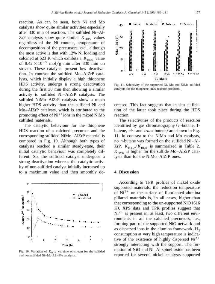
The catalytic behaviour for the thiopheneHDS reaction of a calcined precursor and thecorresponding sulfided NiMo–AlZrP material iscompared in Fig. 10. Although both types ofcatalysts reached a similar steady-state, theirinitial catalytic behaviour was completely dif-ferent. So, the sulfided catalyst undergoes astrong deactivation whereas the catalytic activ-ity of non-sulfided catalyst initially increased upto a maximum value and then smoothly de-
Fig. 10. Variation of K vs. time on-stream for the sulfidedHD S
and non-sulfided Ni–Mo 2.1–9% catalysts.
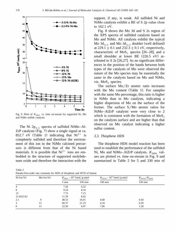
Fig. 11. Selectivity of the supported Ni, Mo and NiMo sulfidedcatalysts for the thiophene HDS reaction products.
creased. This fact suggests that in situ sulfida-tion of the latter took place during the HDSreaction.
The selectivities of the products of reactionŽidentified by gas chromatography n-butane, 1-
.butene, cis- and trans-butene are shown in Fig.11. In contrast to the NiMo and Mo catalysts,no n-butane was formed on the sulfided Ni–Al-ZrP. K rK is summarized in Table 2.HYD HDS
K is higher for the sulfide Mo–AlZrP cata-HYD
lysts than for the NiMo–AlZrP ones.
4. Discussion
According to TPR profiles of nickel oxidesupported materials, the reduction temperatureof Ni2q on the surface of fluorinated aluminapillared materials is, in all cases, higher than
Žthat corresponding to the un-supported NiO 616.K . XPS data and TPR profiles suggest that
Ni2q is present in, at least, two different envi-ronments in all the calcined precursors, i.e.,forming part of the supported NiO network andas dispersed ions in the alumina framework. H 2
consumption at very high temperature is indica-tive of the existence of highly dispersed Ni2q
strongly interacting with the support. The for-mation of NiO and Ni–Al spinel oxide has beenreported for several nickel catalysts supported

( )J. Merida-Robles et al.rJournal of Molecular Catalysis A: Chemical 145 1999 169–181´178
w xon alumina 11,12,23,29 . These species fixed tothe support differ in reducibility and their rela-tive concentration depend on the nickel content,the nature of the support, and the calcination
w xtemperature 12–15 . According to the literaturew x 2q30 , Ni in a spinel-like structure is moredifficult to reduce or sulfide, in consequence the
Ž .high-temperature TPR peak s might be tenta-tively associated with this species, i.e., NiAl O .2 4
Ž .The lower-temperature TPR peak s may beassociated with NiO, which interacts to a lesserextent with the support. On increasing nickelloading the amount of deposited NiO increasesand the interaction of the outer NiO overlayerwith the support decreases. Thus the corre-sponding TPR peak shifts to a lower tempera-
Ž .ture at a high nickel percentage 12 wt.% . Thelow reducibility of nickel as related to its highdispersion has also been observed in other sys-tems like Ni2q-Y zeolites, where reduction and
2q w xagglomeration of Ni are very difficult 31,32 .The XPS analysis of the Ni-based calcined pre-cursors confirms the presence of more than one
2q Žkind of supported Ni species BEs at 854.1.and 856.1 eV . XPS data revealed that only the
fraction of Ni2q which weakly interacts withŽ .the support BE at 854.1 eV could be sulfided,
2q Žbecause the peak at high BE of Ni ;856.eV remains unchanged. XRD data, with weak
˚diffraction lines at 1.71, 1.97 and 2.97 A, insamples with Ni loading higher than 8%, pointto the thermodynamically most stable nickel
w xsulfide phase, NiS 33,34 was formed on sulfid-ing Ni catalysts. It is known that strong metal–support interactions give rise to the appearanceof the NiS phase, whilst Ni S phase is prefer-3 2
entially formed in systems with weak metal–Ž .support interactions e.g., carbon or silica
w x35,36 . Consequently the presence of NiS insulfided Ni catalysts is another indication that,at least a fraction of the Ni2q species stronglyinteracts with the support, as deduced by TPR-H and XPS analyses. The surface SrNi atomic2
ratio obtained by XPS for impregnated samplesranged between 1.05 and 1.47. These valueswere higher than that corresponding to the Ni S3 2
phase and thus the formation of this phase maybe ruled out.
The loading of Mo in Mo and NiMo catalystswas ranged between 3 and 4.3 Mo atomrnm2,since this species is highly dispersed on the
w xsupport as a monolayer 37 . XRD patterns ofNiMo calcined precursors show only the signalscorresponding to MoO , but after sulfidation no3
peak corresponding to MoS is observable. The2
absence of separate nickel sulfide phases in thesulfided NiMo catalysts is attributed to Ni whichmay be incorporated in small amounts into theMoS structure. In fact, the XPS analysis indi-2
cates that the environment of Ni in the sulfidedŽ .NiMo-catalysts BEs852.7 eV is different
Žfrom that in sulfided Ni catalysts 851.3–851.9. 2qeV . Moreover, a total sulfidation of Ni ions
was only possible for NiMo-calcined precur-sors, which could be explained by the fact thatNi2q ions were preferentially incorporated intothe MoO structure before sulfidation and hence3
no interaction with the support would be ex-pected in this case. A square pyramidal arrange-ment of Ni2q ions within the MoS framework,2
similar to that of the millerite structure, hasw xbeen proposed 38–41 and confirmed later by
w xEXAFS spectroscopy 35 . The shift of the XPSsignal Ni 2p at higher BE values in NiMo3r2
materials with respect to the Ni ones may berelated to the presence of Ni atoms in this
w xparticular coordination 42–44 in which nickelexhibits a lower coordination number than in
w xthe nickel sulfide 35 .The Mo 3d and S 2p BEs were about the
same as the sulfide forms of both monometallicand bimetallic Ni–Mo catalysts but the disper-sion of the MoS phase is affected by the2
addition of Ni atoms as promoter. The disper-sion is higher for the catalysts containing Nipromoter atoms, as deduced for the Mo andNi–Mo with the same content of molybdenumfrom the surface MorZr atomic ratios which are
Žhigher for the sulfided NiMo catalysts Table.1 .
In this study, thiophene was used for thecharacterisation of sulfided catalysts. The cat-
( )J. Merida-Robles et al.rJournal of Molecular Catalysis A: Chemical 145 1999 169–181´ 179
alytic behaviour displayed by non-sulfidedNiMo materials suggests that selfsulfidation by
Ž .means of the S of thiophene occurs Fig. 10 .This seems to justify the mechanism of hydro-
w xdesulfurization proposed by Kabe et al. 45–48 ,who concluded that sulfur in the reactiveŽ .thiophene is not directly released as hydrogensulfide but accumulated on the catalysts. Afterreaction, complete sulfidation of the catalystswas detected by XPS analysis, with BE valuesof Ni and Mo being in the range of the sulfidedforms.
The Ni-based catalysts show a promisingŽ y5 y5value between 6=10 to 8=10 molrg
.min K and do not exhibit deactivation. At aHDSŽ .lower temperature of calcination 623 K the
catalyst with the highest Ni loading and sulfidedat 673 K shows the maximum activity with aK value close to 10y4 molrg min in goodHDS
agreement with the maximum found value forŽ .sulfidation Table 2 . These results seem indi-
cate that there are special interactions betweenthe nanoparticles of alumina and nickel sulfidewhich lead to a high dispersion of the activephase and, therefore, to a significant activity.Furthermore, the catalysts do not show deactiva-tion because the acidity of the support is only ofLewis type, and as a consequence of this fact,no formation of coke is observed. In contrast,the Mo catalysts are quickly deactivated, whichcould be originated from the presence of coordi-nation vacancies on the edges of MoS crystal-2
lites in agreement with the low observed SrMoŽ .ratio by XPS for this catalyst Table 1 . H S2
molecules may occupy these vacancies and actas Bronsted acid sites which provoke the forma-¨tion of coke and consequently a drastic decrease
w xof the catalytic activity 49 by blocking thepores and active sites.
The sulfided NiMo–AlZrP catalysts dis-played the highest activity for this reaction, dueto the promotion effect of Ni. XPS analysisindicated that this cation was incorporated to theMoS network. After an initial deactivation of2
the catalyst during the first hour, the activityremains almost constant for a long time. This
deactivation is not related with the support,because it is produced by the Bronsted acid¨centres originated on Mo atoms during the sulfi-dation process, and it is less than that observedfor the MoS catalyst, because the formation of2
these acid sites is only associated with Mow x36,40,41 . The HDS activity of sulfidedNiMo–AlZrP catalysts could be related to the
Žexistence of sulfur vacancies uncoordinated.sites on molybdenum. H S was not formed2
directly from the sulfur compound, but from thesulfur on the catalyst. It has also been proposedthat only sulfur bonded to both Ni and Mo is
w xlabile 48 . The removal of H S will form a new2
vacancy on the catalyst. Thus, a shift of vacancyon the catalyst surface would occur.
The catalysts show high activity for the hy-drodesulfurization of thiophene, particularly thesulfided NiMo–AlZrP catalysts, which exhibitin comparison a higher activity than Ni, Mo andNiMo sulfided catalysts supported on carbonsw x w x50 , zeolites 51 and alumina pillared smectitesw x17 , tested in similar conditions.
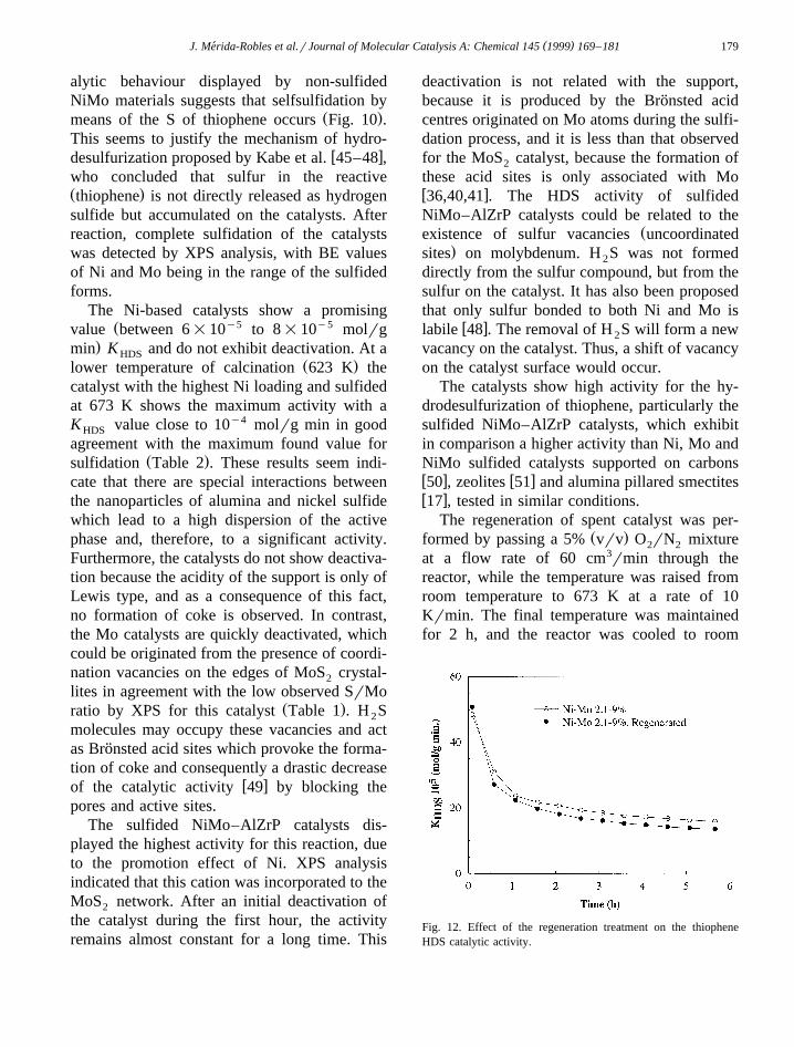
The regeneration of spent catalyst was per-Ž .formed by passing a 5% vrv O rN mixture2 2
at a flow rate of 60 cm3rmin through thereactor, while the temperature was raised fromroom temperature to 673 K at a rate of 10Krmin. The final temperature was maintainedfor 2 h, and the reactor was cooled to room
Fig. 12. Effect of the regeneration treatment on the thiopheneHDS catalytic activity.
( )J. Merida-Robles et al.rJournal of Molecular Catalysis A: Chemical 145 1999 169–181´180
Ž .temperature in a flow of 5% vrv O rN2 2
mixture. Fig. 12 shows that a total regenerationof the catalysts was reached, meaning that thestructure is not affected in this process, byeither segregation or diffusion of the activecomponents of the catalyst.
Finally, it is noticeable the different selectivi-ties of these catalysts, thus Ni-based does notproduce butane as a hydrogenation product ofreaction. The hydrogenation ability of the cata-lyst can be interpreted by the presence of activehydrogen, furthermore, the hydrogenation activ-ity is higher for transition metal sulfides whosestructure enables the formation of intercalatedcompounds, such as MoS . Hydrogen activation2
takes place through intercalation in MoS , that2
is by proton permeation in the van der Waalsgap and by stabilising the electron charge in the
w x2p-band of sulfur 52,53 . The edge sites aresuitable for alkene adsorption during hydrogena-
w xtion or isomerization reactions 54 .
5. Conclusions
Fluorinated alumina pillared a-zirconiumphosphate materials have shown to be appropri-ate supports for preparing sulfided catalysts.The Ni–Mo oxides precursors revealed to beactive in the HDS reaction of thiophene, whichmeans that there is an in situ sulfidation of theoxidic phase. The Ni-based catalysts havepromising activities which are sustained for along time, and may be increased when theformation of the oxidic phase was obtained at a
Ž .lower temperature 623 K in this way avoidingthe formation of a spinel structure on the nanos-tructured alumina. Interestingly, these com-pounds are not active for hydrogenation reac-tions and the products of reaction of thiopheneare exclusively butenes. The Ni–Mo based cata-lysts are highly dispersed and the most activephases, with K values higher than 2=10y4
HDSŽ .molrg min after 300 min owing to the pro-
moter effect of Ni. In addition, regeneration ofthe catalysts could be achieved by treatment
Ž .with 5% vrv O rN at 673 K without loss of2 2
activity.
Acknowledgements
This research was supported by CICYTŽ .Spain Proyect MAT97-906 and by E.U. Pro-gramme BRIT-EURAM Contract BRE2-CT-93-0450.
References
w x1 O. Weisser, S. Landa, Sulphide Catalysts, Their Propertiesand Applications, Pergamon, New York, 1973.
w x2 F.E. Massoth, in: Advances in Catalysis and Related Sub-jects, Vol. 27, Academic Press, New York, 1978, p. 265.
w x Ž .3 B. Delmon, in: H.F. Barry, P.C.H. Mitchell Eds. , Proceed-ings, 3rd International Conference on the Chemistry andUses of Molybdenum, Climax Molybdenum, Ann Arbor,1979, p. 73.
w x Ž .4 P. Grange, Catal. Rev. Sci. Eng. 21 1980 135.w x Ž .5 P. Ratnasamy, S. Sivasanker, Catal. Rev. Sci. Eng. 22 1980
401.w x6 B.C. Gates, J.R. Katzer, G.C.A. Schuit, Chemistry of Cat-
alytic Processes, McGraw-Hill, New York, 1979, p. 390.w x7 R. Cid, J. Neira, J. Godoy, J.M. Palacios, A. Lopez-Agudo,´
Ž .Appl. Catal. A: General 125 1995 169.w x8 R. Cid, J. Neira, A. Lopez-Agudo, Bol. Soc. Chil. Quim. 40´
Ž .1995 371.w x9 R. Cid, S. Bendezu, J. Godoy, A. Lopez-Agudo, Bol. Soc.´
Ž .Quim. 40 1995 135.w x10 Y. Okamoto, H. Tomioka, T. Imanaka, S. Teranshi, J. Catal.
Ž .66 1980 93.w x Ž .11 J. Olorunyolemi, R. Kydd, J. Catal. 158 1996 583.w x Ž . Ž .12 M. Wu, D.M. Hercules, J. Phys. Chem. 83 15 1979 2003.w x13 B. Scheffer, P. Molhock, J.A. Moulijn, Appl. Catal. 46
Ž .1989 11.w x14 A. Gil, A. Dıaz, L.M. Gandıa, M. Montes, Appl. Catal. A´ ´
Ž .109 1994 167.w x Ž .15 L.M. Gandıa, M. Montes, J. Mol. Catal. 94 1994 347.´w x Ž .16 L.M. Occelli, R.J. Rennard, Catal. Today 2 1988 309.w x17 J.T. Kloprogge, W.J.J. Welters, E. Booy, V.H.J. de Beer,
R.A. van Sante, J.W. Geus, J.B.H. Jansen, Appl. Catal. A 97Ž .1993 77.
w x18 J. Merida-Robles, P. Olivera-Pastor, A. Jimenez-Lopez, E.´ ´ ´Ž . Ž .Rodrıguez-Castellon, J. Phys. Chem. 100 35 1996 14726.´ ´
w x19 J. Merida-Robles, P. Olivera-Pastor, E. Rodrıguez-Castellon,´ ´ ´Ž .A. Jimenez-Lopez, J. Catal. 169 1997 317.´ ´
w x20 J.F. Moulder, W.F. Stickle, P.E. Sobol, K.D. Bombeu, in: J.Ž .Chastain Ed. , Handbook of X-Ray Photoelectron Spec-
troscopy, Perkin-Elmer, 1992.w x21 P. Arnoldy, J.C.M. de Jongue, J.A. Moulijn, J. Phys. Chem.
Ž .89 1985 4517.w x Ž .22 Y.J. Huang, J.A. Schwarz, Appl. Catal. 36 1988 163.
( )J. Merida-Robles et al.rJournal of Molecular Catalysis A: Chemical 145 1999 169–181´ 181
w x23 L. Daza, B. Pawelec, J.A. Anderson, J.L.G. Fierro, Appl.Ž .Catal. A 87 1992 145.
w x Ž .24 B. Scheffer, P.J. Magnus, J.A. Moulijn, J. Catal. 121 199018.
w x Ž .25 R. Burch, A. Collins, J. Catal. 97 1986 385.w x Ž .26 Y. Okamoto, H. Nakano, T. Shimakawa, J. Catal. 50 1977
447.w x27 A. Arteaga, J.L.G. Fierro, F. Delannay, B. Delmon, Appl.
Ž .Catal. 26 1986 227.w x28 S. Mendioroz, J.M. Palacios, J.L.G. Fierro, A. Lopez-Agudo,´
Ž .Bull. Soc. Chim. Belg. 96 1987 891.w x Ž .29 J.W.E. Coenen, Appl. Catal. 75 1991 193.w x30 J.M. Rynkowski, T. Paryjczal, M. Lenik, Appl. Catal. 106
Ž .1993 73.w x31 Ch. Minchev, V. Knarizer, L. Kosova, V. Pechev, W. Grun-
Ž .sser, F. Schimidt, in: L.V.C. Rees Ed. , Proceedings 5thConference on Zeolites, Heyden, London, 1980, p. 335.
w x Ž .32 M. Suzuki, K. Tsutsumi, H. Takahashi, Zeolites 2 1982 87.w x Ž .33 T. Rosenquist, J. Iron Steel Inst. 176 1954 37.w x34 P.J. Magnus, PhD Thesis, University of Amsterdam, The
Netherlands, 1989.w x Ž .35 S.P.A. Louwers, R. Prins, J. Catal. 133 1992 94.w x Ž .36 R. Burch, A. Collins, Appl. Catal. 18 1985 373.w x Ž .37 Y. Okamoto, A. Maezawa, T. Imanaka, J. Catal. 120 1989
29.w x Ž .38 P. Ratnasamy, S. Sivasanker, Catal. Rev. Sci. Eng. 22 1980
401.w x39 B.S. Clausen, B. Lengeler, R. Candia, J. Als-Nielsen, H.
Ž .Topsoe, Bull. Soc. Chim. Belg. 90 1981 1249.
w x40 H. Topsøe, B.S. Clausen, N.-Y. Topsøe, E. Pedersen, W.Niemann, A. Muller, H. Bogge, B. Lengeler, J. Chem. Soc.¨ ¨
Ž .Faraday Trans. 83 1987 2157.w x Ž .41 N.-Y. Topsøe, H. Topsøe, F.E. Massoth, J. Catal. 119 1989
252.w x42 I. Alstrup, L. Chorkendorff, R. Candia, B.S. Clusen, H.
Ž .Topsoe, J. Catal. 77 1982 397.w x43 U.S. Ozkan, L. Zhang, S. Ni, E. Moctezuma, J. Catal. 148
Ž .1994 181.w x Ž .44 L. Blanchard, J. Grimblot, J.P. Bonnelle, J. Catal. 98 1986
229.w x45 T. Kabe, W. Qian, S. Ogawa, A. Ishihara, J. Catal. 143
Ž .1993 239.w x46 W. Qian, A. Ishihara, S. Ogawa, T. Kabe, J. Phys. Chem. 98
Ž .1994 907.w x Ž .47 T. Kabe, W. Qian, A. Ishihara, J. Phys. Chem. 98 1994
912.w x Ž .48 T. Kabe, W. Qian, A. Ishihara, J. Catal. 149 1994 171.w x Ž .49 S.H. Yang, C.N. Satterfield, J. Catal. 81 1983 168.w x50 S. Eijsbouts, J.N.M. van Gestel, E.M. van Oers, R. Prins,
J.A.R. van Veen, V.H.J. de Beer, Appl. Catal. A: GeneralŽ .119 1994 293.
w x51 W.J. Welters, G. Vorbeck, H.W. Zandbergen, J.W. de Haan,Ž .V.H.J. de Beer, R.A. van Sante, J. Catal. 150 1994 155.
w x52 R. Schollhorn, M. Kumpersand, D. Plorin, J. Less-CommonŽ .Met. 58 1978 55.
w x Ž .53 R. Schollhorn, Angew. Chem. 92 1980 1015.w x54 A. Andreev, Ch. Vladov, L. Phahov, P. Atanasova, Appl.
Ž .Catal. A: General 108 1994 97.