characterizing impacts of high temperature and pressures ... · between the inside wall and outside...
TRANSCRIPT
Characterizing Impacts of High Temperature and Pressures in Oxy-Coal Combustion Systems
Department of Energy under Cooperative Agreement No. DE-FE0025168
2017 NETL CO2 Capture Technology Project Review Meeting
Omni William Penn Hotel; Pittsburgh, PA
August 25, 2017

2
HTHP Program
▪ Key second generation candidates for CO2 capture include high temperature and pressurized oxy-firing of coal
▪ Promising technologies because of potential to increase efficiency, lower capital costs, avoid air ingress and reduce oxygen requirements
▪ Unquantified challenges exist in the practical utilization of these technologies
Enabling Technologies for Advanced Oxy-Coal Combustion Systems
Characterizing Impacts of High Temperature and Pressures in Oxy-Coal
Combustion Systems (HTHP)September, 2015 – August 2018

3
HTHP Timeline and Budget
September 1, 2015 – August 31, 2018

4
HTHP Timeline and Budget
September 1, 2015 – August 31, 2018

5
HTHP Timeline and Budget
Total Budget$1,570,596
Total Federal$1,251,541

6
Program Approach
Validate
High Temp
Mechanisms
Use CFD
Modeling for
Conceptual
High Temp
High Pressure
Utility Boiler
DesignDesign
High Temp
Firing System
Validate
High Pressure
Mechanisms
High Temp
Atmospheric
Particle
Behavior
Elevated Temp
High Pressure
Thermal &
Particle
Behavior
Modeling
Experimental
High Temp
Atmospheric
Thermal Profile

High Temp
(Minimum Recycle)
Design
High Temp
Firing System
Experimental Modeling
Oxy-fuel Combustor
100 kW – Atmospheric
L1500 Multi-fuel Furnace
1.5 MW – Atmospheric
300 kW Pressurized
Entrained Flow Reactor Modeling
Elevated
Temperature &
Pressurized
(17 bar)
Design
Pressurized
Firing System
Experimental
Technical Approach
7
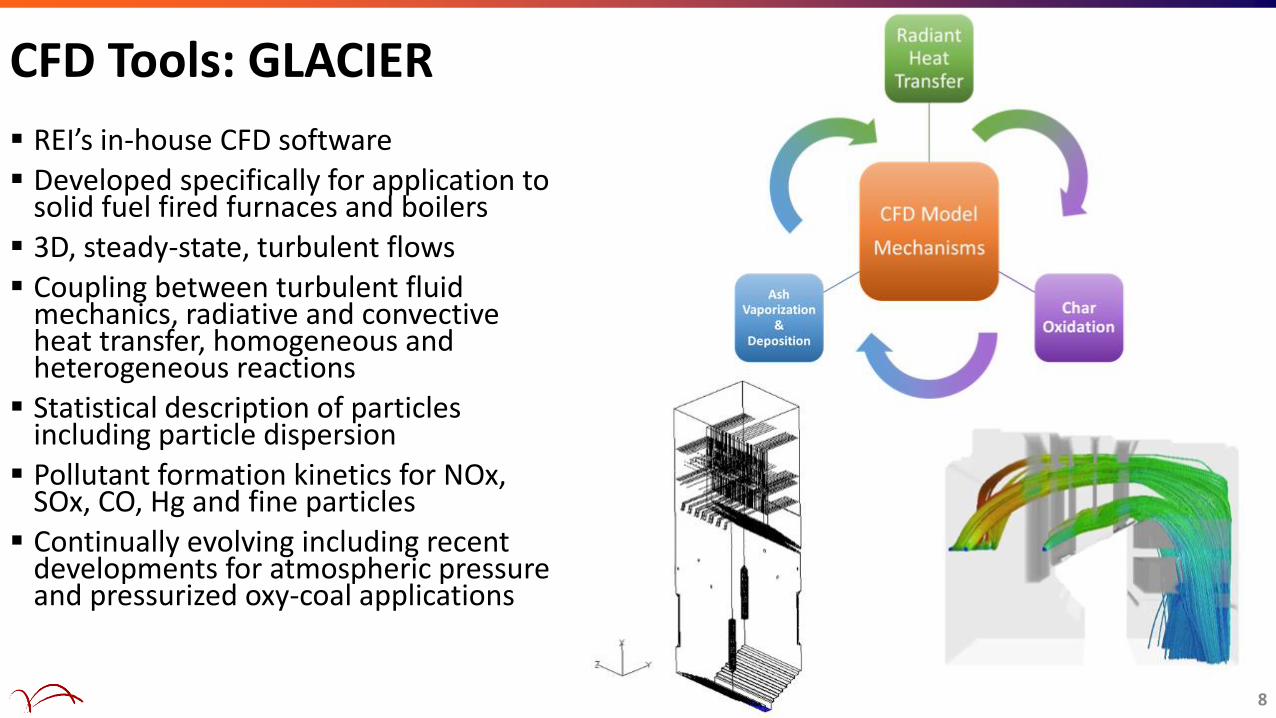
CFD Tools: GLACIER
▪ REI’s in-house CFD software
▪ Developed specifically for application to solid fuel fired furnaces and boilers
▪ 3D, steady-state, turbulent flows
▪ Coupling between turbulent fluid mechanics, radiative and convective heat transfer, homogeneous and heterogeneous reactions
▪ Statistical description of particles including particle dispersion
▪ Pollutant formation kinetics for NOx, SOx, CO, Hg and fine particles
▪ Continually evolving including recent developments for atmospheric pressure and pressurized oxy-coal applications
8

100 kW Oxy-Fuel Combustor
Specifications
▪ 100 kW (0.25 MBtu/hr) Firing Rate
▪ Main Burner Zone 20 in x 48 in
▪ Quartz Windows for Optical Access of Flame
▪ Vertical Height 12.5 ft
▪ Horizontal Convective Section 12 ft
Research
▪ Ash Formation• Aerosols• Deposition• Trace Elements
▪ Sorbent Development
▪ Optical Diagnostics• Flame, Radiation & Flow Field
9
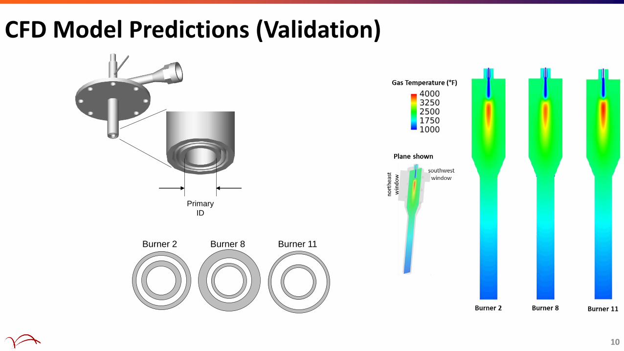
CFD Model Predictions (Validation)
10
Burner 2 Burner 11Burner 8
Primary
ID

11
K-type thermocouples located in the top section (3 flush with the inside wall, 3 at the midpoint between the inside wall and outside shell).
CFD Model Predictions (Validation)

Ash aerosol PSD and deposits (vertical, inside and outside)
Horizontal deposits:
Outside deposits: loosely bound, easily removed by vigorous shaking.
Inside deposits: tightly bound, removed only by scraping.12
outside deposits
13
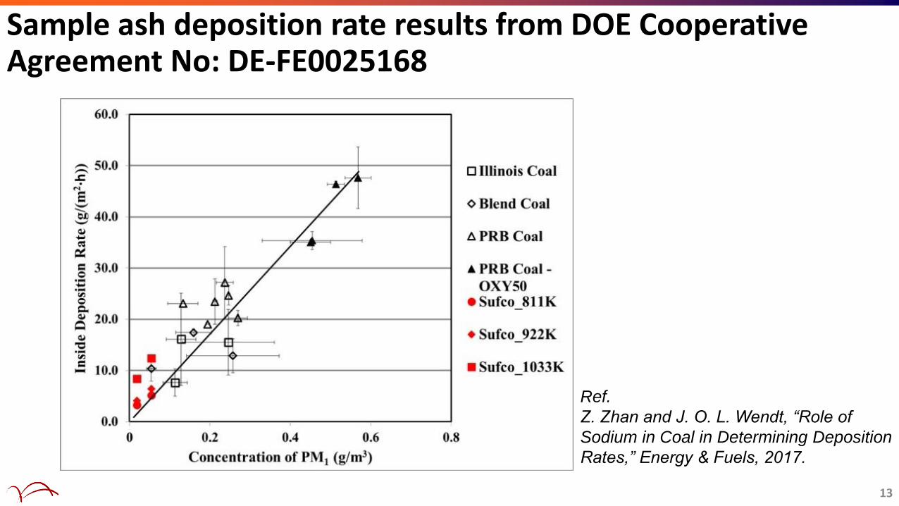
Sample ash deposition rate results from DOE Cooperative Agreement No: DE-FE0025168
Ref.
Z. Zhan and J. O. L. Wendt, “Role of
Sodium in Coal in Determining Deposition
Rates,” Energy & Fuels, 2017.

14
1.5 MW CFD-Based Burner DesignPulverized Coal Combustor (L1500)
FD and Recycle Fan
Convective Section
BaghouseAir/FGR/O2 Control
Radiative Section
Burner
Sample Ports
Unique L1500 Capabilities:
- Realistic Burner Turbulent Mixing Scale
- Realistic Radiative Conditions
- Realistic Time – Temperature Profile
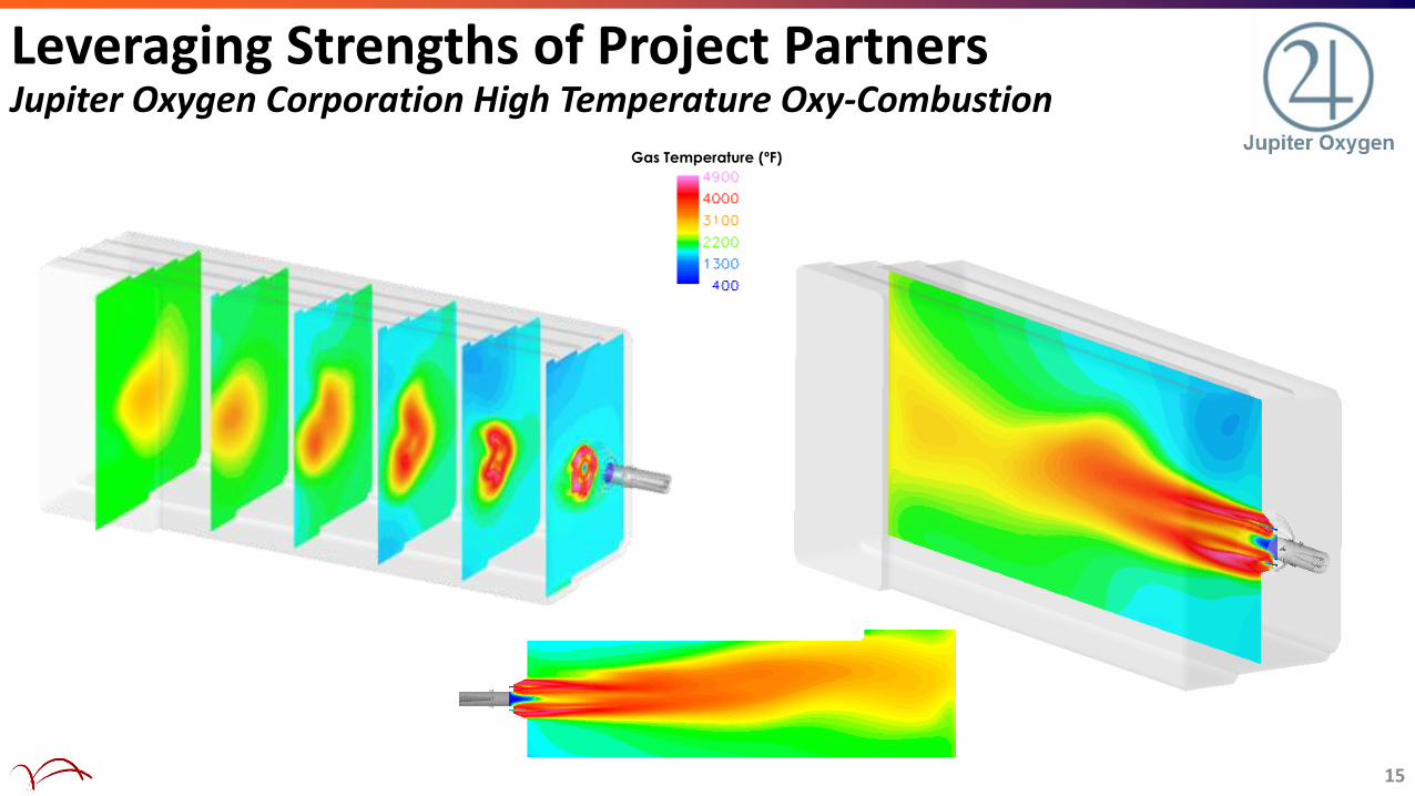
Gas Temperature (ºF)
Leveraging Strengths of Project PartnersJupiter Oxygen Corporation High Temperature Oxy-Combustion
15

16
1.5 MW CFD-Based Burner Design
Highly Mixed Case
Design Case
Elongated
Heat Release
Rapid Mixing
Wall Temperature (°F)
Gas Temperature (°F)

17
Results: Air-Fired Flame

18
1.5 MW CFD Model PredictionsJuly, 2016 High Temperature Oxy-Coal Tests

19
Experimental Results: Furnace Heat Balance
Coal
3.00 MBtu/hr
Preheated Gas0.01 MBtu/hr
Flue Gas
0.33 MBtu/hr
Co
olin
g Pan
els
0.59MBtu/hr
Co
olin
g Co
ils
0.94MBtu/hr
Co
olin
g Jackets
0.31MBtu/hr
Wall H
eat Loss
0.80MBtu/hr
2.69 MBtu/hr 2.64 MBtu/hr
Heat Loss From Furnace Measured Heat Removal
1.3 % Difference

20
CFD Model Predictions (Validation)
▪ Wall surface temperature was an important determining factor for burner design
▪ CFD model predictions of wall temperature are in good agreement for the un-swirled and swirled conditions through Section 7 of the furnace

Conduct experiments at University of Utah’s Entrained
Flow Pressurized Reactor
Validate simulations of high pressure
300 kW Entrained Flow Pressurized Reactor (EFPR)
Next Steps
21

▪ Two years into the program: eight of eleven technical tasks have been completed
▪ 100 kW simulations provide a good representation of the thermocouple data and wall heat flux as measured by multi-depth thermocouples in the wall
▪ Submicron particle concentration is directly correlated with formation rates of the initial deposit layer, which subsequently facilitates the capture of larger particles
▪ A model-based approach was used to represent the physical and thermochemical phenomena associated with ash transformation
▪ The predicted mass of the submicron particles is comparable to the experimental data in both absolute value and relative value
▪ CFD model predictions of deposition of the submicron particles are consistent with the experimental data in terms of trend and magnitude
▪ 1.5 MW simulations for multiple parameter variations based on a simple burner concept in the L1500 have been completed
▪ Burner design efforts to increase peak flame temperatures are typically counter to efforts to distribute heat axially
▪ Extended heat release correlated to particulate burnout and the percentage of exit CO2 evolved indicate best performance for protecting combustion components
▪ CFD model predictions of wall temperature are in good agreement for the un-swirled and swirled conditions through Section 7 of the furnace
▪ Experimental campaign for elevated temperature and high pressure oxy-coal combustion has begun22
Summary

This material is based upon work supported by the Department of Energy under Cooperative Agreement No. DE-FE0025168.
This report was prepared as an account of work sponsored by an agency of the United States Government. Neither the United States Government nor any agency thereof, nor any of their employees, makes any warranty, express or implied, or assumes any legal liability or responsibility for the accuracy, completeness, or usefulness of any information, apparatus, product, or process disclosed, or represents that its use would not infringe privately owned rights. Reference herein to any specific commercial product, process, or service by trade name, trademark, manufacturer, or otherwise does not necessarily constitute or imply its endorsement, recommendation, or favoring by the United States Government or any agency thereof. The views and opinions of authors expressed herein do not necessarily state or reflect those of the United States Government or any agency thereof.
Acknowledgment
23

Disclaimer: This report was prepared as an account of work sponsored by an agency of the United Stales Government. Neither the United States Government nor any agency thereof, nor any of their employees, makes any warranty, express or implied, or assumes any legal liability or responsibility for the accuracy, completeness, or usefulness of any information, apparatus, product, or process disclosed, or represents that its use would not infringe privately owned rights. Reference herein to any specific commercial product, process, or service by trade name, trademark, manufacturer, or otherwise docs not necessarily constitute or imply its endorsement, recommendation, or favoring by the United States Government or any agency thereof. The views and opinions of authors expressed herein do not necessarily state or reflect those of the United States Government or any agency thereof.
Disclaimer
24

25
Thank You