charged particles in fields - university of michigan
TRANSCRIPT

The electron beam used to study motion ofcharged particles in electric and/or magneticfields.
CHARGEDPARTICLES IN FIELDS
Physics 241/261
Fall 2012
1 IntroductionThe precise control of charged particles in electromagnetic fields is crucial to a wide range of advances
in experimental physics. From large scale experiments like those that study subatomic particles at CERNto small table-top experiments that trap a single ion, physicists around the world use electromagnetic fieldsto control and manipulate matter. In experiments large and small, the precise control of the particles withthe fields is necessary in order for the data to be the best possible.
In today’s experiment, we will study the basics of motion of charged particles in fields by observinga beam of electrons in an electric field, a magnetic field, and combined electric and magnetic fields. Theideas you will encounter form the basis of experimental particle control using electromagnetic fields.
By the end of this lab, you should be able to predict the path of an electron (or any other chargedparticle) in a constant electric or magnetic field and understand how the two cases differ. You should un-derstand how the physical variables you control (voltages and currents) relate to the electric and magneticfield strengths in the apparatus and the electron kinematics.
2 EquipmentThe setup for this experiment is a bit more involved than the ones you have used in previous experi-
ments. The equipment includes a cathode ray tube with an inclosed beam gun and electrostatic deflectionplates (for electric field control), as well as external Helmholtz coils (for magnetic field control). All ofthe apparatus should be assembled for you when you arrive in lab, and we ask you not to move any of thewires before, during, or after the experiment. The two exceptions are the red jumper cables and the leadsto the Extech power supply. Both will be discussed in Section 5.
• Electron beam tube with grid (TEL525)
• Tel Atomic TEL 2813 high voltage power supply
• University of Michigan High Voltage Power Supply (UMHVPS)
• Extech power supply
1
Deflection plates
Mica sheet
Vd plug
Va plug
Vd plug
Electron accelerating anode (Va)
Anode slit to define beam
Electron filament
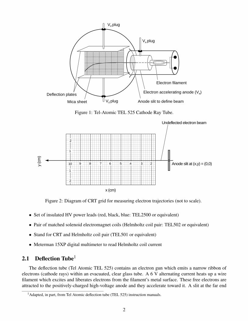
Figure 1: Tel-Atomic TEL 525 Cathode Ray Tube.
y (c
m)
x (cm)
2
10
1
1
9 8 7 6 5 4 3 2
2
Anode slit at (x,y) = (0,0)
Undeflected electron beam
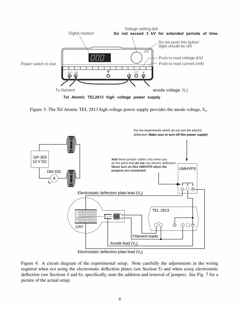
Figure 2: Diagram of CRT grid for measuring electron trajectories (not to scale).
• Set of insulated HV power leads (red, black, blue: TEL2500 or equivalent)
• Pair of matched solenoid electromagnet coils (Helmholtz coil pair: TEL502 or equivalent)
• Stand for CRT and Helmholtz coil pair (TEL501 or equivalent)
• Meterman 15XP digital multimeter to read Helmholtz coil current
2.1 Deflection Tube1
The deflection tube (Tel Atomic TEL 525) contains an electron gun which emits a narrow ribbon ofelectrons (cathode rays) within an evacuated, clear glass tube. A 6 V alternating current heats up a wirefilament which excites and liberates electrons from the filament’s metal surface. These free electrons areattracted to the positively-charged high-voltage anode and they accelerate toward it. A slit at the far end
1Adapted, in part, from Tel Atomic deflection tube (TEL 525) instruction manuals.
2

of the anode (left end of anode as shown in Figure 1) forms a beam of electrons which travels into themain spherical section of the tube. The electrons (cathode rays) are intercepted by a flat mica sheet, oneside of which is coated with a luminescent screen and the other printed with a centimeter graticule screen(Figure 2). Thus, the path followed by the electrons is made visible. The mica sheet is held at 15◦ to theaxis of the tube by two electric-field deflecting plates.
2.2 Helmholtz CoilsThe Helmholtz coils are used to provide a relatively uniform magnetic field in the center of the tube.
The two coils are wired in series so that the field from each solenoid adds together in the same direction toyield a uniform magnetic field in the region between them. Note that although the magnetic field is in thehorizontal direction, it will produce a deflection in the up/down (vertical) direction (see Figure 5). Whenusing the “right hand rule," remember that it refers to positive charges, while our beam is composed ofnegative charges. The diagrams shown in this write-up correspond to a negatively charged particle like theelectron. Positive charges would be deflected in the opposite direction.
2.3 Extech Power SupplyThe Extech power supply should be familiar from several previous experiments. In this experiment,
we will use it to control the current delivered to the Helmholtz coils, IB, and thus the magnetic field thatthey produce, ~B.
2.4 UMHVPSThis power supply should be familiar from the electrostatics experiment. In this experiment, it will
control the voltage Vd across the plates on the top and bottom of the mica screen, and thus the electric fieldproduced between them, ~E.
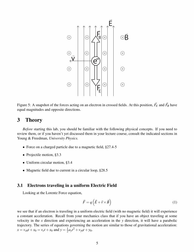
2.5 TEL 2813The TEL 2813 power supply, shown in Figure 3, controls the electron gun in the back of the deflection
tube. Specifically, it controls the anode voltage Va. This is the potential difference across which electronsare accelerated before emerging as our electron beam. The display on the front can either indicate thevoltage being applied or the current being delivered. We are interested in the voltage. In order to displaythe voltage, press the “kV" so that the red “kV" indicator lights up. When using the TEL 2813, you shouldnot exceed the recommended voltage of 3 kV for long periods of time.
WARNINGTurn off power supplies when changing leads or polarity. Turn down voltages when not making measure-ments. Do not touch exposed metal plugs when high voltage is present. Do not remove leads by pulling onwires; instead, grasp the insulated banana plug. Have your instructor examine the setup before you turnon the power supplies.
3
anode voltage
Figure 3: The Tel Atomic TEL 2813 high voltage power supply provides the anode voltage, Va.
GP-303�12 V DC
A
DM-332
IB
- +
- +∼
TEL 2813
CRT
Electrostatic deflection plate lead (Vd)
Electrostatic deflection plate lead (Vd)
Anode lead (Va)
Filament leads
For the experiments which do not use the electric �deflection: Make sure to turn off this power supply!
UMHVPS
��Add these jumper cables only when you�do the parts that do not use electric deflection.�Never turn on this UMHVPS when the�jumpers are connected.
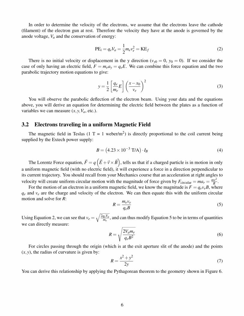
Figure 4: A circuit diagram of the experimental setup. Note carefully the adjustments in the wiringrequired when not using the electrostatic deflection plates (see Section 5) and when using electrostaticdeflection (see Sections 4 and 6); specifically, note the addition and removal of jumpers. See Fig. 7 for apicture of the actual setup.
4
e-
E
v
BFB
FE
Figure 5: A snapshot of the forces acting on an electron in crossed fields. At this position, ~FE and ~FB haveequal magnitudes and opposite directions.
3 TheoryBefore starting this lab, you should be familiar with the following physical concepts. If you need to
review them, or if you haven’t yet discussed them in your lecture course, consult the indicated sections inYoung & Freedman, University Physics.
• Force on a charged particle due to a magnetic field, §27.4-5
• Projectile motion, §3.3
• Uniform circular motion, §3.4
• Magnetic field due to current in a circular loop, §28.5
3.1 Electrons traveling in a uniform Electric FieldLooking at the Lorentz Force equation,
~F = q(~E +~v×~B
)(1)
we see that if an electron is traveling in a uniform electric field (with no magnetic field) it will experiencea constant acceleration. Recall from your mechanics class that if you have an object traveling at somevelocity in the x direction and experiencing an acceleration in the y direction, it will have a parabolictrajectory. The series of equations governing the motion are similar to those of gravitational acceleration:x = vx0t + x0 = vet + x0 and y = 1
2ayt2 + vy0t + y0.
5
In order to determine the velocity of the electrons, we assume that the electrons leave the cathode(filament) of the electron gun at rest. Therefore the velocity they have at the anode is governed by theanode voltage, Va and the conservation of energy:
PEi = qeVa =12
mev2e = KE f (2)
There is no initial velocity or displacement in the y direction (vy0 = 0, y0 = 0). If we consider thecase of only having an electric field, F = meay = qeE. We can combine this force equation and the twoparabolic trajectory motion equations to give:
y =12
[qe
meE](
x− x0
ve
)2
(3)
You will observe the parabolic deflection of the electron beam. Using your data and the equationsabove, you will derive an equation for determining the electric field between the plates as a function ofvariables we can measure (x,y,Va, etc.).
3.2 Electrons traveling in a uniform Magnetic FieldThe magnetic field in Teslas (1 T = 1 weber/m2) is directly proportional to the coil current being
supplied by the Extech power supply:
B =(4.23×10⁻³ T/A
)· IB (4)
The Lorentz Force equation, ~F = q(~E +~v×~B
), tells us that if a charged particle is in motion in only
a uniform magnetic field (with no electric field), it will experience a force in a direction perpendicular toits current trajectory. You should recall from your Mechanics course that an acceleration at right angles tovelocity will create uniform circular motion with the magnitude of force given by Fcircular = mar =
mv2
R .For the motion of an electron in a uniform magnetic field, we know the magnitude is F = qeveB, where
qe and ve are the charge and velocity of the electron. We can then equate this with the uniform circularmotion and solve for R:
R =meve
qeB(5)
Using Equation 2, we can see that ve =√
2qeVame
, and can thus modify Equation 5 to be in terms of quantitieswe can directly measure:
R =
√2Vame
qeB2 (6)
For circles passing through the origin (which is at the exit aperture slit of the anode) and the points(x,y), the radius of curvature is given by:
R =x2 + y2
2y(7)
You can derive this relationship by applying the Pythagorean theorem to the geometry shown in Figure 6.
6

2
10
1
1
9 8 7 6 5 4 3 2
2
x
R
Electromagnetic deflection(circular trajectory)
Electron beam passingthrough anode slit at (0,0)
y
R−y
Figure 6: An example of a circular trajectory.
3.3 Electrons traveling in balanced Electric and Magnetic FieldsIf an electric field of strength ~E is applied simultaneously and perpendicularly to an magnetic field ~B,
so that the two deflections are in the same plane but opposite in direction (see Fig. 5), this can yield abalance of forces. To achieve balanced force, the fields must satisfy:
FE(= qeE) = FB(= qeveB), (8)
and therefore the velocity must obey
ve =
∣∣∣∣EB∣∣∣∣ (9)
We can measure the velocity using this equation since we will determine the strength of the mag-netic field from the current in the coils and we will determine the magnitude of the electric field in theelectrostatic deflection experiment.
4 Experiment: Electric Field DeflectionThe purpose of this experiment is to observe the parabolic trajectory of the electron beam in an electric
field, and to use this data to determine the magnitude of the electric field.Check that the red jumper cables that short the inputs to the UMHVPS are not attached and turn on
the UMHVPS high voltage power supply in order to establish a potential difference Vd across the twodeflecting plates. On the UMHVPS deflection plate HV supply, the voltage readout will display the propervalue of Vd . Recall that a pair of parallel conductive plates charged to some potential difference will createan electric field between the plates.
A method for determining the electric field is to observe the deflection of the electron beam. Thismethod has one significant advantage. The trajectory of the beam depends only on the beam’s velocity,the beam’s position, and the magnitude of the electric field at that point in space.
You should also note that the deflection plates do not extend all the way to the x = 0 point due to thespherical shape of the apparatus. For this reason, we need to determine the point at which the electrons
7
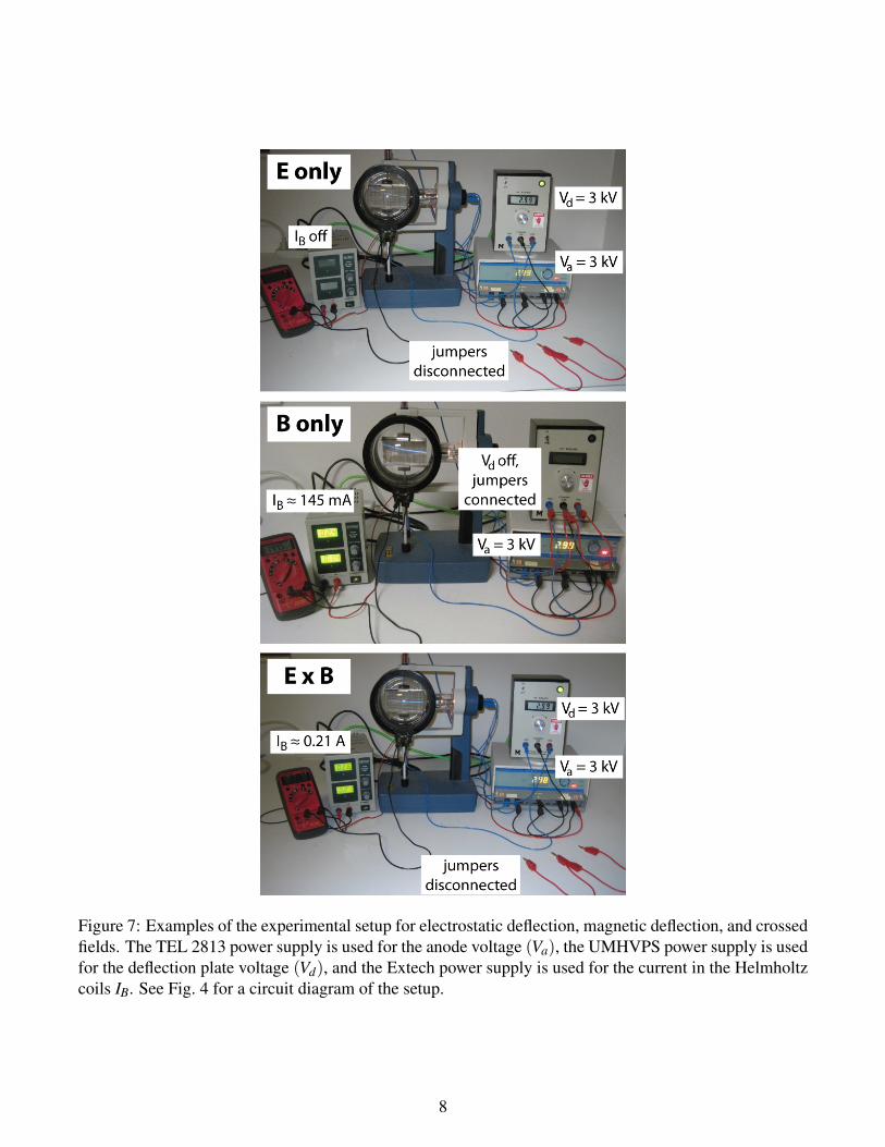
Figure 7: Examples of the experimental setup for electrostatic deflection, magnetic deflection, and crossedfields. The TEL 2813 power supply is used for the anode voltage (Va), the UMHVPS power supply is usedfor the deflection plate voltage (Vd), and the Extech power supply is used for the current in the Helmholtzcoils IB. See Fig. 4 for a circuit diagram of the setup.
8

(x-x ) (cm )2 20
20 30 40 6050 70
0.4
0.8
1.2
0
1.6
2.0
y (c
m)
V = 2 kVd
V = 3 kVd
Figure 8: A sample plot with two sets of data sharing the axes.
enter the electric field (the region between the parallel plates). Though it varies slightly between thedifferent setups, we will assume x0 = 2 cm.
Set the anode voltage, Va, to 3 kV. Make sure the “kV” button is pressed and the red “kV" indicator islit, so that the TEL 2813 power supply will display the voltage; see Figure 3.
Using two different potential voltages (Vd = 2 kV and Vd = 3 kV) carefully record the x and y valuesof eight points along this beam path. Use the same x coordinates for both Vd values and remember thatpoints with large x values are preferred. When you have recorded your points, turn off the UMHVPSpower supply.
Plot y vs. (x−xoff)2 using both sets of your data. Find the slope for each line on your plot. An example
plot is given in Fig. 8.Combine Equations 2 and 3 by solving for the velocity in one of the equations and substituting this
into the other equation. Rearrange your new equation until you have an expression for the electric field interms of the slope of your graph. (Hint: What do we expect for the slope of a graph of y vs. (x− x0)
2 ifEquation 3 is correct?) Use your equation to determine the magnitude of the electric field for each of yourVd values.
There is a simpler way to determine the magnitude of the electric field between the plates if we assumethey form a parallel plate capacitor. For an ideal parallel plate capacitor, the electric field can easily becomputed from the voltage difference between the two plates Vd and their separation d: E = Vd/d. Ifyou do not remember what constitutes an ideal parallel plate capacitor, it may be useful to refer to theCapacitance experiments you performed earlier in the semester.
Record d, the separation distance between the plates. Use this value to calculate E =Vd/d. Compare
9
this to the value you measured from your graph. You should find a large difference between the two. Whatphysical property makes the Vd/d calculation less reliable?
5 Experiment: Magnetic Field DeflectionIn this experiment we will study the motion of electrons in a uniform magnetic field and verify that
they travel in a circle, with a radius given by Equation 6.Because we do not want an electric field, turn off the UMHVPS and connect jumper cables to short
the inputs to the power supply. This will ensure that the deflection plates are grounded so that no chargewill build up; thus, the electric field between the plates will be zero.
Set Va to ∼3 kV.Observe the path of the beam. It should be undeflected (is it?). Turn on the Extech power supply to
turn on the magnetic field from the Helmholtz coils. Set IB to 0.150 A or so. Is the electron trajectoryvisually different than in the electric field case?
Spend a short time adjusting the settings of the different power supplies in use. Observe, with referenceto the mica screen, that:
1. with Va fixed, the radius of the electron path, R, decreases with an increase in coil current IB andhence the magnetic field, ~B);
2. with IB fixed, the radius increases with an increase in anode potential Va, and hence a higher electronvelocity;
3. the path of the electron beam is approximately circular, the deflection being in a plane perpendicularto the direction of the magnetic field, ~B.
With Va = 3 kV, adjust IB until the beam has a "nice" coordinate (e.g. x = 8.0 cm, y = 1.0 cm ratherthan x = 8.3 cm, y = 0.85 cm). Choosing a point with a large x value will help reduce measurement error.Use this coordinate to calculate R in SI units using Equation 7.
Using Equation 6 and the known values of me and qe, calculate R in SI units. Compare this to yourprevious value.
We will look at both upward and downward deflection of the electron beam. For each given value ofVa, tune IB until the beam passes through your coordinate (or (x,−y)) and record this value.
Repeat the measurements for the same Va’s but with the magnetic field direction reversed. The easiestway to reverse the direction of the magnetic field is to reverse the direction of the current through the coilsby exchanging the leads to the Extech power supply.
Your observations should confirm that an electron of mass me and charge qe = e moving at right anglesto a magnetic field ~B will experience a central deflecting magnetic force, ~FB, constraining it to a circularpath with an inward radial acceleration,~ar, in accordance with the equations in Section 3.2.
Using your upward deflection data for Va = 3 kV, calculate B from Equation 4. Then, along with theknown value of me = 9.109× 10⁻³¹ kg, calculate qe. Compare your measured value to the known valueof qe = −1e = −1.602× 10⁻¹⁹ C. In the next lab, we will use all of the data in the table to perform astatistical analysis.
Do you see an obvious difference between the upward and downward deflections? If so, briefly de-scribe it. Note: Not all tables will have this difference.
Why do we take measurements with the magnetic field in two different directions? Hint: Is there anyadditional magnetic field we have neglected?
Compare the radius measured with the coordinates on the mica screen to the radius calculated fromthe measurements of the individual parameters in Equation 6.
10
Electron beam
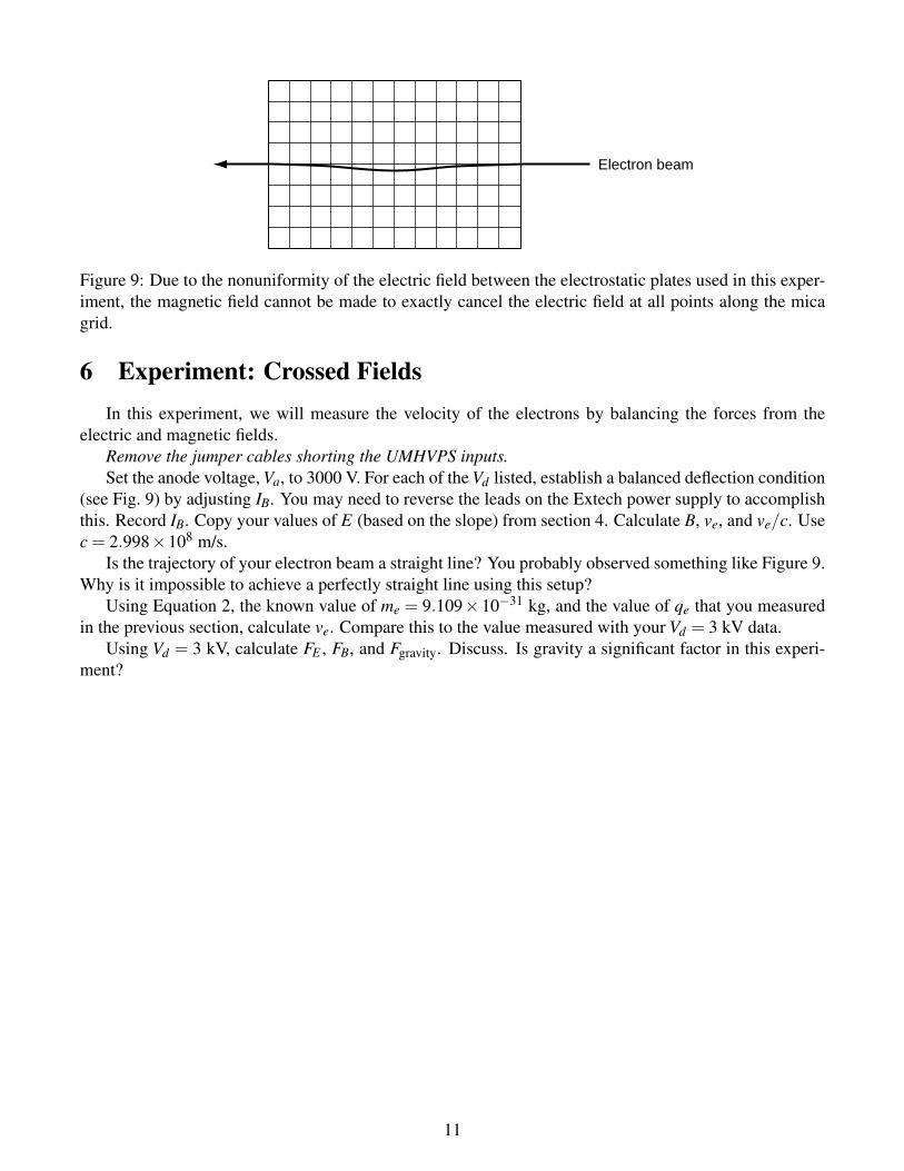
Figure 9: Due to the nonuniformity of the electric field between the electrostatic plates used in this exper-iment, the magnetic field cannot be made to exactly cancel the electric field at all points along the micagrid.
6 Experiment: Crossed FieldsIn this experiment, we will measure the velocity of the electrons by balancing the forces from the
electric and magnetic fields.Remove the jumper cables shorting the UMHVPS inputs.Set the anode voltage, Va, to 3000 V. For each of the Vd listed, establish a balanced deflection condition
(see Fig. 9) by adjusting IB. You may need to reverse the leads on the Extech power supply to accomplishthis. Record IB. Copy your values of E (based on the slope) from section 4. Calculate B, ve, and ve/c. Usec = 2.998×10⁸ m/s.
Is the trajectory of your electron beam a straight line? You probably observed something like Figure 9.Why is it impossible to achieve a perfectly straight line using this setup?
Using Equation 2, the known value of me = 9.109×10⁻³¹ kg, and the value of qe that you measuredin the previous section, calculate ve. Compare this to the value measured with your Vd = 3 kV data.
Using Vd = 3 kV, calculate FE , FB, and Fgravity. Discuss. Is gravity a significant factor in this experi-ment?
11