charisma - metaxas · kostas metaxas design awards & innovations 01 2 x australian export...
TRANSCRIPT
K O S T A S M E T A X A S D E S I G N
C h a r i s m a
K O S T A S M E T A X A S D E S I G N
K O S T A S M E T A X A S D E S I G NK O S T A S M E T A X A S D E S I G N
C o n t e n t s
Aw a r d s & I n n o v a t i o n s 0 1
3 D e c a d e s o f “ H i - E n d ” 0 2
L i s t e n i n g R e f e r e n c e 0 5
D e s i g n P h i l o s o p h y 0 6
O p e r a t i n g I n s t r u c t i o n s 1 1
W h a t t h e c r i t i c s s a y. . . 1 2
S p e c i f i c a t i o n s 1 4
C o n t r o l s & F e a t u r e s 1 5
M a i n t e n a n c e 1 6
S c h e m a t i c 1 8
E C C o n f o r m i t y 1 9

K O S T A S M E T A X A S D E S I G N
A w a r d s & I n n o v a t i o n s
012 X AUSTRALIAN EXPORT AWARD, BHP STEEL DESIGN AWARD,
runner up in AUSTRALIAN SMALL BUSINESS AWARDS
First - Amplifiers- No wire construction with
shortest possible signal path
First - 'Capacitorless' circuits in Audio design
First power amplifier can put full power into
8 ohm load at 1.0MegaHertz!
(refer to article in USA "AUDIO").
First - High Speed diodes in power supply
First - DAC to use lowest jitter 'APOGEE CLOCK'
First - FULL range and high efficiency electrostatic
First - Audio Manufacturer to use BMW-Porsche CAD-PCB
software design systems
Yo u a r e a b o u t t o l i s t e n t o
a n a m p l i f i e r w h i c h h a s
e v o l v e d f r o m o v e r 2 0 y e a r s
o f d e d i c a t e d l i s t e n i n g a n d
t h e a p p l i c a t i o n o f t h e
s t a t e - o f - t h e - a r t i n e v e r y
p r o c e s s o f d e s i g n a n d
m a n u f a c t u r e . I ’ m s u r e
y o u ’ l l e n j o y l i s t e n i n g t o i t
a s m u c h a s I d o .
- K o s t a s M e t a x a s D E S I G N E R

K O S T A S M E T A X A S D E S I G N
3 D e c a d e s o f H i - E n d : 1 9 8 0 ’s
02Opulence Preamplifier Assembly Engraving
Kostas Metaxas circa 1985 Soliloquy Monoblocks
Ecstatic & Revelation Electrostatics
K O S T A S M E T A X A S D E S I G N
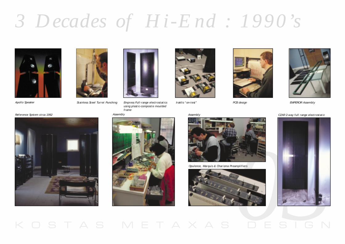
3 D e c a d e s o f H i - E n d : 1 9 9 0 ’s
03Apollo Speaker
Reference System circa 1992 Assembly Assembly CZAR 2-way full range electrostatic
Opulence, Marquis & Charisma Preamplifiers
Stainless Steel Turret Punching Iraklis “on-test”Empress Full-range electrostaticsusing plastic-composite mouldedframe
PCB design EMPEROR Assembly
K O S T A S M E T A X A S D E S I G N04
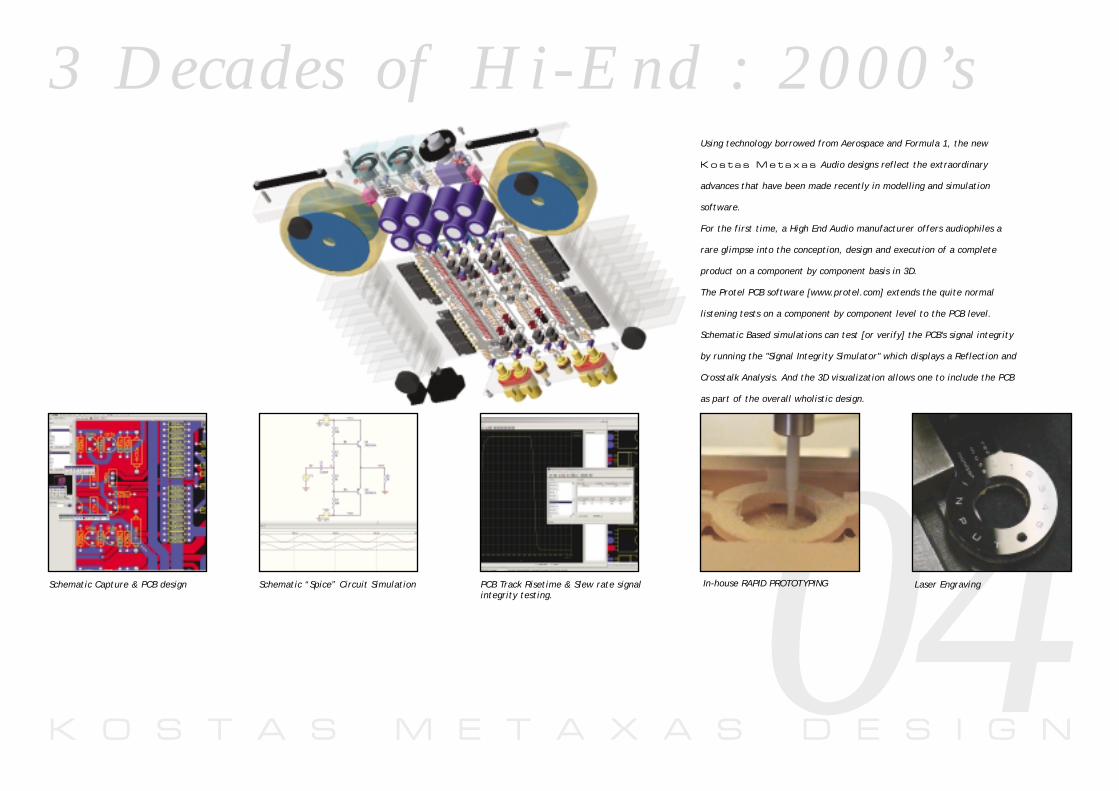
Using technology borrowed from Aerospace and Formula 1, the new
K o s t a s M e t a x a s Audio designs reflect the extraordinary
advances that have been made recently in modelling and simulation
software.
For the first time, a High End Audio manufacturer offers audiophiles a
rare glimpse into the conception, design and execution of a complete
product on a component by component basis in 3D.
The Protel PCB software [www.protel.com] extends the quite normal
listening tests on a component by component level to the PCB level.
Schematic Based simulations can test [or verify] the PCB's signal integrity
by running the "Signal Integrity Simulator" which displays a Reflection and
Crosstalk Analysis. And the 3D visualization allows one to include the PCB
as part of the overall wholistic design.
Schematic Capture & PCB design Schematic “Spice” Circuit Simulation PCB Track Risetime & Slew rate signalintegrity testing.
In-house RAPID PROTOTYPING Laser Engraving
3 D e c a d e s o f H i - E n d : 2 0 0 0 ’s

K O S T A S M E T A X A S D E S I G N
L i s t e n i n g P h i l o s o p h y
05The only way to design state-of-the-art audio equipment is to have
first-hand experience with the finest available recording equipment AND
playback equipment.
This is important for two reasons; it ensures that our designs work and
'mate-well' with other products and that their resolution is not limited
by the weakest link in the playback 'chain'.
K o s t a s M e t a x a s products have been conceived using
extensive listening tests with a variety of state-of-the-art ancillary
equipment for more than 25 years.
Our amplifiers have been designed using a variety of state-of-the-art
phono playback equipment and our ABSOLUTE REFERENCE -
a custom-made battery-powered Stellavox SM-8 Tape Recorder using
1/4" tape at 30 ips and a Stellavox TD-9 using 1/2" tape at 30 ips
specially calibrated for the Bruel & Kjaer 4003 1/4" omnidirectional
electrostatic instrumentation microphones.
R E F E R E N C E
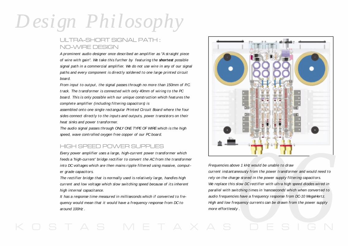
ULTRA-SHORT SIGNAL PATH :
NO-WIRE DESIGNA prominent audio designer once described an amplifier as "A straight piece
of wire with gain". We take this further by featuring the shortest possible
signal path in a commercial amplifier. We do not use wire in any of our signal
paths and every component is directly soldered to one large printed circuit
board.
From input to output, the signal passes through no more than 150mm of P.C.
track. The transformer is connected with only 40mm of wiring to the PC
board. This is only possible with our unique construction which features the
complete amplifier (including filtering capacitors) is
assembled onto one single rectangular Printed Circuit Board where the four
sides connect directly to the inputs and outputs, power transistors on their
heat sinks and power transformer.
The audio signal passes through ONLY ONE TYPE OF WIRE which is the high
speed, wave controlled oxygen free copper of our PC board.
HIGH SPEED POWER SUPPLIESEvery power amplifier uses a large, high-current power transformer which
feeds a 'high-current' bridge rectifier to convert the AC from the transformer
into DC voltages which are then mains ripple filtered using massive, comput-
er grade capacitors.
The rectifier bridge that is normally used is relatively large, handles high
current and low voltage which slow switching speed because of its inherent
high internal capacitance.
It has a response time measured in milliseconds which if converted to fre-
quency would mean that it would have a frequency response from DC to
around 100Hz .
K O S T A S M E T A X A S D E S I G N
D e s i g n P h i l o s o p h y
06Frequencies above 1 kHz would be unable to draw
current instantaneously from the power transformer and would need to
rely on the charge stored in the power supply filtering capacitors.
We replace this slow DC rectifier with ultra high speed diodes wired in
parallel with switching times in 'nanoseconds' which when converted to
audio frequencies have a frequency response from DC-10 MegaHertz.
High and low frequency currents can be drawn from the power supply
more effortlessly .
D e s i g n P h i l o s o p h y
K O S T A S M E T A X A S D E S I G N
D e s i g n P h i l o s o p h y
07
LOW NOISE, HIGH SPEED VOLTAGEREGULATOR DESIGN.
The most significant difference between VALVE and TRANSISTOR circuits
is the amplifier/power supply interaction.
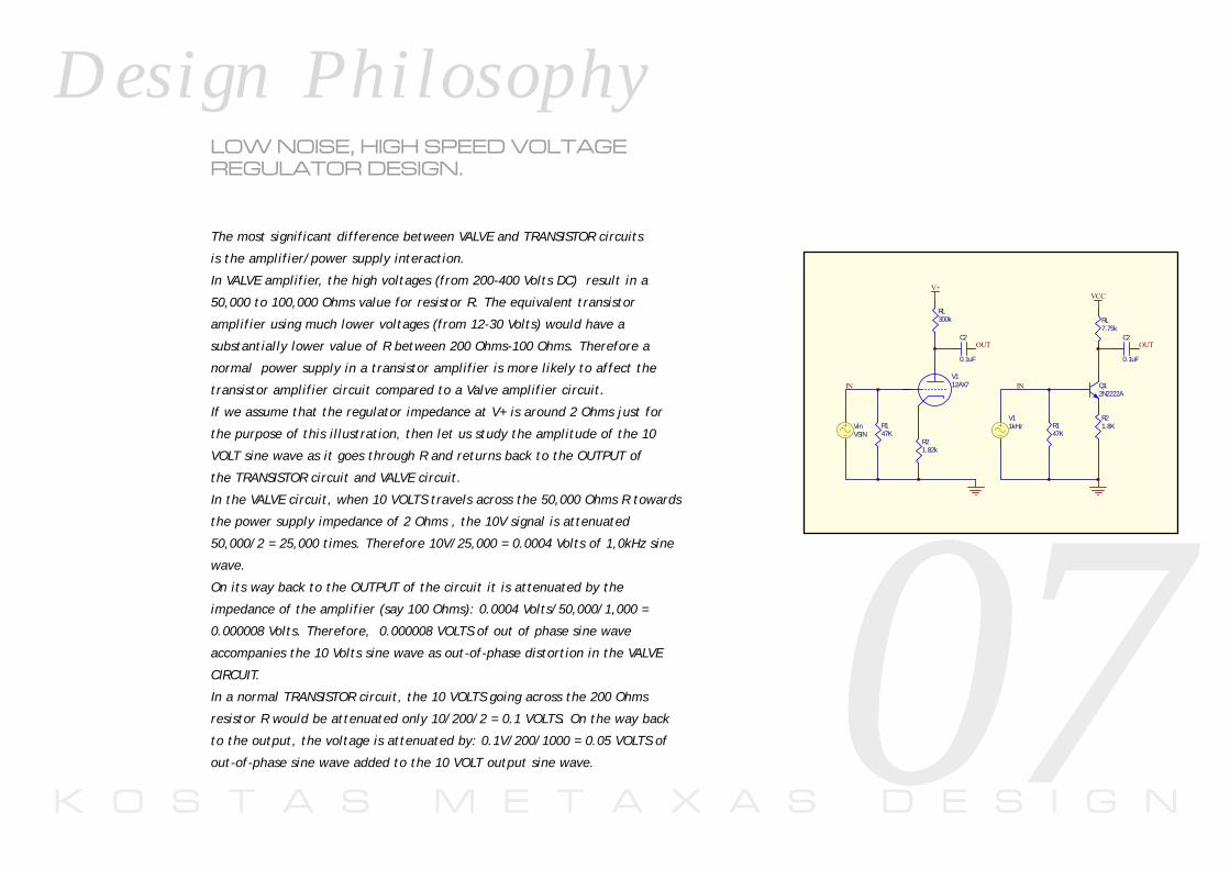
In VALVE amplifier, the high voltages (from 200-400 Volts DC) result in a
50,000 to 100,000 Ohms value for resistor R. The equivalent transistor
amplifier using much lower voltages (from 12-30 Volts) would have a
substantially lower value of R between 200 Ohms-100 Ohms. Therefore a
normal power supply in a transistor amplifier is more likely to affect the
transistor amplifier circuit compared to a Valve amplifier circuit.
If we assume that the regulator impedance at V+ is around 2 Ohms just for
the purpose of this illustration, then let us study the amplitude of the 10
VOLT sine wave as it goes through R and returns back to the OUTPUT of
the TRANSISTOR circuit and VALVE circuit.
In the VALVE circuit, when 10 VOLTS travels across the 50,000 Ohms R towards
the power supply impedance of 2 Ohms , the 10V signal is attenuated
50,000/2 = 25,000 times. Therefore 10V/25,000 = 0.0004 Volts of 1,0kHz sine
wave.
On its way back to the OUTPUT of the circuit it is attenuated by the
impedance of the amplifier (say 100 Ohms): 0.0004 Volts/50,000/1,000 =
0.000008 Volts. Therefore, 0.000008 VOLTS of out of phase sine wave
accompanies the 10 Volts sine wave as out-of-phase distortion in the VALVE
CIRCUIT.
In a normal TRANSISTOR circuit, the 10 VOLTS going across the 200 Ohms
resistor R would be attenuated only 10/200/2 = 0.1 VOLTS. On the way back
to the output, the voltage is attenuated by: 0.1V/200/1000 = 0.05 VOLTS of
out-of-phase sine wave added to the 10 VOLT output sine wave.
V112AX7
R147K
R21.82k
RL300k
C2
0.1uF
V+
VinVSIN
IN
OUT
V11kHz R1
47K
RL7.75k
R21.8K
Q12N2222A
VCC
IN
C2
0.1uF
OUT
K O S T A S M E T A X A S D E S I G N
D e s i g n P h i l o s o p h y
08In a normal Transistor circuit, the 'phase distortion' is 0.5% as compared to
0.000008% for a normal VALVE circuit .
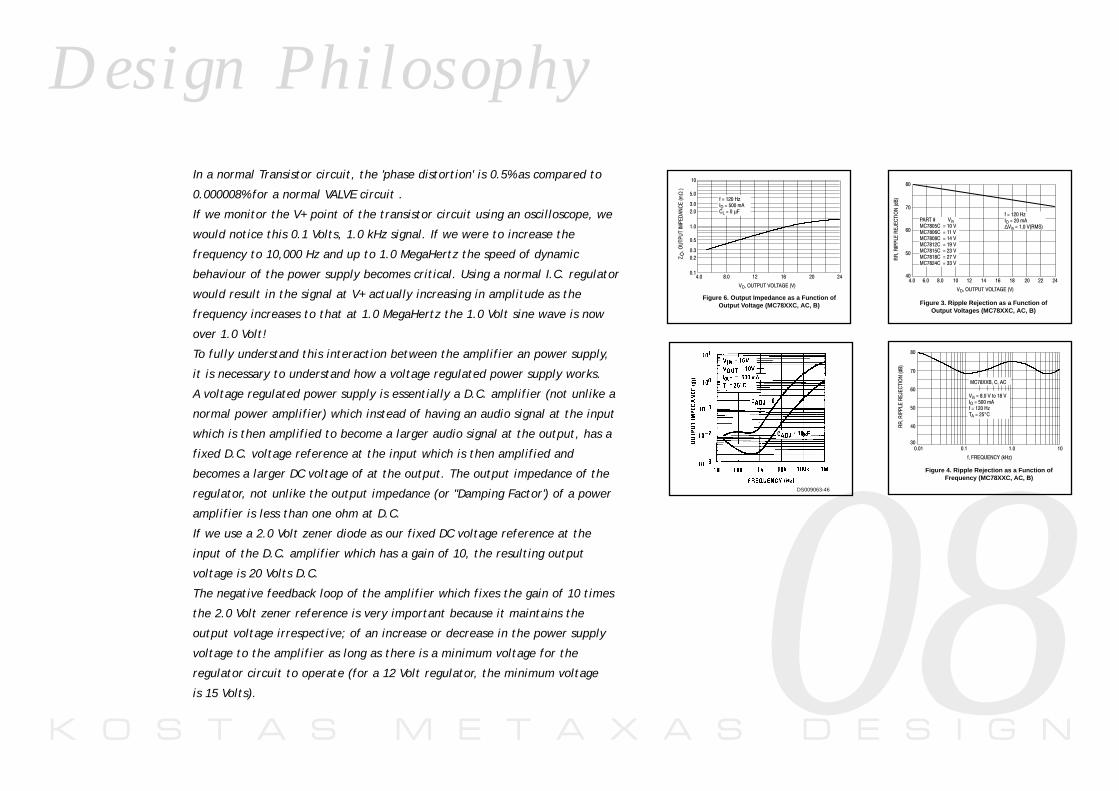
If we monitor the V+ point of the transistor circuit using an oscilloscope, we
would notice this 0.1 Volts, 1.0 kHz signal. If we were to increase the
frequency to 10,000 Hz and up to 1.0 MegaHertz the speed of dynamic
behaviour of the power supply becomes critical. Using a normal I.C. regulator
would result in the signal at V+ actually increasing in amplitude as the
frequency increases to that at 1.0 MegaHertz the 1.0 Volt sine wave is now
over 1.0 Volt!
To fully understand this interaction between the amplifier an power supply,
it is necessary to understand how a voltage regulated power supply works.
A voltage regulated power supply is essentially a D.C. amplifier (not unlike a
normal power amplifier) which instead of having an audio signal at the input
which is then amplified to become a larger audio signal at the output, has a
fixed D.C. voltage reference at the input which is then amplified and
becomes a larger DC voltage of at the output. The output impedance of the
regulator, not unlike the output impedance (or "Damping Factor') of a power
amplifier is less than one ohm at D.C.
If we use a 2.0 Volt zener diode as our fixed DC voltage reference at the
input of the D.C. amplifier which has a gain of 10, the resulting output
voltage is 20 Volts D.C.
The negative feedback loop of the amplifier which fixes the gain of 10 times
the 2.0 Volt zener reference is very important because it maintains the
output voltage irrespective; of an increase or decrease in the power supply
voltage to the amplifier as long as there is a minimum voltage for the
regulator circuit to operate (for a 12 Volt regulator, the minimum voltage
is 15 Volts).
Figure 6. Output Impedance as a Function ofOutput Voltage (MC78XXC, AC, B)
+
"4)
Ω
! $
5
.,23,4",µ
Figure 4. Ripple Rejection as a Function ofFrequency (MC78XXC, AC, B)
!
%
"&'
./"0123
#
$
+"#!77'""
,!!,4.,23,°"
Figure 3. Ripple Rejection as a Function ofOutput Voltages (MC78XXC, AC, B)
!
#
$
$ ! $ !
%
"&'
()* +"#!"*,+"#!$"*,+"#!!"*, +"#!"*,-+"#!"*,+"#!!"*,#+"#! "*,
.,23,4∆,+6
DS009063-46
K O S T A S M E T A X A S D E S I G N
D e s i g n P h i l o s o p h y
09
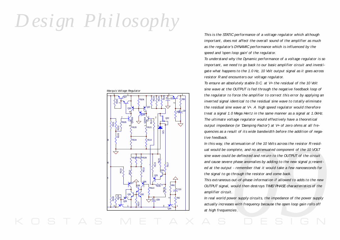
This is the STATIC performance of a voltage regulator which although
important, does not affect the overall sound of the amplifier as much
as the regulator's DYNAMIC performance which is influenced by the
speed and 'open loop gain' of the regulator.
To understand why the Dynamic performance of a voltage regulator is so
important, we need to go back to our basic amplifier circuit and investi-
gate what happens to the 1.0 Hz, 10 Volt output signal as it goes across
resistor R and encounters our voltage regulator.
To ensure an absolutely stable D.C. at V+ the residual of the 10 Volt
sine wave at the OUTPUT is fed through the negative feedback loop of
the regulator to force the amplifier to correct this error by applying an
inverted signal identical to the residual sine wave to totally eliminate
the residual sine wave at V+. A high speed regulator would therefore
treat a signal 1.0 Mega Hertz in the same manner as a signal at 1.0kHz.
The ultimate voltage regulator would effectively have a theoretical
output impedance (or 'Damping Factor') at V+ of zero ohms at all fre-
quencies as a result of its wide bandwidth before the addition of nega-
tive feedback.
In this way, the attenuation of the 10 Volts across the resistor R resid-
ual would be complete, and no attenuated component of the 10 VOLT
sine wave could be deflected and return to the OUTPUT of the circuit
and cause severe phase anomalies by adding to the new signal p;resent-
ed at the output - remember that it would take a few nanoseconds for
the signal to go through the resistor and come back.
This extraneous out-of-phase information if allowed to adds to the new
OUTPUT signal, would then destroys TIME/PHASE characteristics of the
amplifier circuit.
In real world power supply circuits, the impedance of the power supply
actually increases with frequency because the open loop gain rolls off
at high frequencies .
45
R42
R38
R36
1
2
3
C9
R41
1
2
3Q34
C10
56
4
R128R127R126
Q18 Q22
Q19
Q25
Q27 Q26
Q24
Q31 Q32
Q28
Q23
Q17
Q29
1
2
3
1
2
3
Q30
2
13
Q20
0A
7
86
Q20
0B
R102
R103
R101
R108
R116
R115
R125
R124
R123
R117
R119
R118
R122
R105
R100
R109
R107
R106
R121R120
R104R1
12
R111
R113
R110
R114
CE9
CE10
DZ1
L
Marquis Voltage Regulator
K O S T A S M E T A X A S D E S I G N
D e s i g n P h i l o s o p h y
10
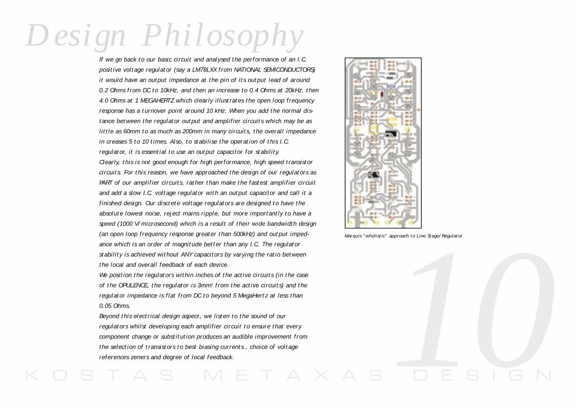
If we go back to our basic circuit and analysed the performance of an I.C.
positive voltage regulator (say a LM78LXX from NATIONAL SEMICONDUCTORS)
it would have an output impedance at the pin of its output lead of around
0.2 Ohms from DC to 10kHz, and then an increase to 0.4 Ohms at 20kHz, then
4.0 Ohms at 1 MEGAHERTZ which clearly illustrates the open loop frequency
response has a turnover point around 10 kHz. When you add the normal dis-
tance between the regulator output and amplifier circuits which may be as
little as 60mm to as much as 200mm in many circuits, the overall impedance
in creases 5 to 10 times. Also, to stabilise the operation of this I.C.
regulator, it is essential to use an output capacitor for stability.
Clearly, this is not good enough for high performance, high speed transistor
circuits. For this reason, we have approached the design of our regulators as
PART of our amplifier circuits, rather than make the fastest amplifier circuit
and add a slow I.C. voltage regulator with an output capacitor and call it a
finished design. Our discrete voltage regulators are designed to have the
absolute lowest noise, reject mains ripple, but more importantly to have a
speed (1000 V/microsecond) which is a result of their wide bandwidth design
(an open loop frequency response greater than 500kHz) and output imped-
ance which is an order of magnitude better than any I.C. The regulator
stability is achieved without ANY capacitors by varying the ratio between
the local and overall feedback of each device.
We position the regulators within inches of the active circuits (in the case
of the OPULENCE, the regulator is 3mm! from the active circuits) and the
regulator impedance is flat from DC to beyond 5 MegaHertz at less than
0.05 Ohms.
Beyond this electrical design aspect, we listen to the sound of our
regulators whilst developing each amplifier circuit to ensure that every
component change or substitution produces an audible improvement from
the selection of transistors to best biasing currents , choice of voltage
references zeners and degree of local feedback.
Marquis “wholistic” approach to Line Stage/Regulator

K O S T A S M E T A X A S D E S I G N
O p e r a t i n g I n s t r u c t i o n s
11Steps for Connection
1. Ensure that the ON/OFF switch on the back panel is in the OFF position before connecting the amplifier into your system.
2. Once connected, ensure that there are no 'short circuits' in the speaker wires, then proceed to switch the unit ON.
Note: For the best results, it is recommended that the unit is powered on for at least 15minutes before critical listening is attempted.
DC Protection Circuits
The output stage of the preamplifier is connected to a DC protection circuit which activates a relay if it senses any DC before it can cause any damage to your speakers.
Mains Fuse
A 2AMP SLOW BLOW DA205 Type fuse is located on the AC MAINS SOCKET. If this blows,simply replace with the same rating fuse. If the fuse continues to blow, please refer to theMaintenance Section of this manual for further instructions.
Serviceability
The complete active circuitry of the amplifier including primary filtering capacitors are allmounted to the large single ground P.C.B. Easy access to the board is maintained by simplyremoving the base to gain access to the 'component side' for servicing.

K O S T A S M E T A X A S D E S I G N
W h a t t h e c r i t i c s s a y . . .
12"The Metaxas analyses the message with a fantastic precision; it is able toreveal a great deal of micro-information which is normally difficult or almostimpossible to hear. According to us, the Charisma is a step towards a true andavailable High Fidelity without compromise". Jean Hiraga/Patrick Vercher, LA NOUVELLE REVUE DU SON, France.
"I also found that I clearly preferred the Metaxas with a vinyl source. Musicseemed less clinical though it was as detailed and informative as with a linelevel source. Vocalists were more characterful, realistic and convincing". M a l c o l m S t e w a r d , A U D I O P H I L E E n g l a n d .
" The Metaxas gave an effortless, polished sound for choir recordings and repro-duced voices very smoothly without the slightest trace of harshness. One almostfelt reminded of an excellent tube amplifier": M . K u c e r a , S O U N D M A G A Z I N E S w i t z e r l a n d .
" We auditioned the Charisma using recordings with large orchestra arrange-ments as well as the small ensembles-all with the same results: three dimen-sional, life-like musical performance within realistic acoustical boundaries. " E r n i e F i s c h e r, T H E I N N E R E A R R E P O R T, C a n a d a .
" ... because of the stress laid on it in the literature, I spend some time listen-ing via the phono input to several alternative pickup cartridges, thus renewingacquaintance with a number of long forgotten LP' s to which it did full justice". G e o f f H o r n , G R A M O P H O N E , E n g l a n d .
K O S T A S M E T A X A S D E S I G N
W h a t t h e c r i t i c s s a y . . .
13
"Between the poles-not extremes, lively walks Metaxas without caring aboutthe esoteric space or the drive of others, but also without denying his owncharacter, namely not to drown everything in neutrality.Between Italy (CABRE)and Tokyo (ROTEL) the mids are where the Metaxas duo (Charisma/Iraklis) areunique; lots of tonal colours, body, drive finish ,precision and impulsivity...recommended for the years without vinyl."U l r i c h M i c h a l i k , H I F I E X C L U S I V , G e r m a n y.
" With more sense for the finer things, but not without liveliness, thus in summary most consistently, present the amps of Kostas Metaxasthemselves.Combined with the right speaker ,they can please both ear andeye."D i r k S o m m e r H I F I E X C L U S I V G e r m a n y
" The overall sound is undoubtedly both fascintating and convincing, half waybetween the crystalline purity and imaging of the best solid state components(mid and high frequencies) and the velvety personality of high class valve units(for example conrad johnson)". G i a n f r a n c o M a c h e l l i S T E R E O , I t a l y .
" When going back to our reference preamplifier (after listening to theCharisma), the sound was less sweet and a little sterile". K l a u s R e n n e r D A S O H R , G e r m a n y,
" It is a very smooth-handling unit, as quiet and precise as they come, easy touse ... I would have no hesitation in recommending it to anyone willing tospend ... especially anyone who uses a moving coil cartridge, for which theCharisma would seem to be ideal". J u l i a n H i r s c h , S T E R E O R E V I E W , U S A .
K O S T A S M E T A X A S D E S I G N
S p e c i f i c a t i o n s
141. LINE STAGE: The Line stage features an identical circuit topology and DC
servo amplifier as used in the Phono Stage except that it is optimised for lin-
ear frequency amplification. To entirely eliminate the sonic degradation of
using a BALANCE potentiometer in the signal path, the BALANCE control is tied
via a secondary network to the inverse feedback loop.
2. POWER SUPPLY: A 200W large toroidal transformer, RFI input mains filter
and massive 50,000uF of primary capacitance before reaching the regulation
circuits.
D.C. regulation is accomplished via a circuit built around two high speed, low
noise integrated circuits with discrete voltage reference.
The positive Master circuit derives its positive reference voltage from a
selected, low noise zener in an unusual manner - from the regulated output.
The negative circuit tracks the positive Master and therefore ensures that
symmetrical positive and negative supplies are within millivolts of each other
- important in D.C. amplifier designs.
The unique feature of this circuit is that it has been developed in conjunction
with the Phono Stage and Output Stage to eliminate the need for stabilising
bypass capacitors which store H.F. energy and cause serious sound quality
anomalies.
3. DC PROTECTION: A circuit built around a dual F.E.T. Integrated Circuit moni-
tors the left and right output stage and controls a relay in series with the
outputs. If a voltage greater than 0.6V DC is sensed, it automatically disables
the signal to the outputs and shorts the input of the following Power Amplifier.
When the fault is removed, the relay trips back into operation.
OPTIONAL RIAA PHONO STAGE:
Input micro switches allow over 69 different combinations of input impedance, whilst
the phono input stage can be configured for operation with either Moving Magnet or
Moving Coil cartridges.The RIAA equalisation is generated via selected polystyrene
capacitors and 1% metal film resisters in the inverse feedback loop.
The overall open-loop gain of this stage has been optimised using local feedback in
the voltage gain stages to approximate the RIAA time constants before the applica-
tion of a minimal amount of overall feedback. This allows us to minimise the stability
compensation to ensure the high speed (greater than 10MHz) operation of this circuit.
The DC operating point is stabilised with the use of a low drift F.E.T. input servo Op
Amp which feeds micro-volts to the inverting arm of the differential input to entirely
eliminate the need for any input or output capacitors in the signal path.
S p e c i f i c a t i o n s
FREQUENCY RESPONSE : DC - 5.0MHz (-3dB)
VOLTAGE OUTPUT : 15VRMS per channel into 50 Ohms with no more than 0.05%
T.H.D.
SLEW RATE : Greater than 1000V/us small and
large signal
T.H.D. : Less than 0.05% 20Hz-20KHz
I.M.D.(S.M.P.T.E.) : Less than 0.05%
SIGNAL/NOISE : -117DBV unweighed input shorted
SENSITIVITY : 26dB
INPUT IMPEDANCE : 100kOhms in parallel with 11pF

K O S T A S M E T A X A S D E S I G N
C o n t r o l s & Fe a t u r e s
15
K O S T A S M E T A X A S D E S I G N
M a i n t e n a n c e
16
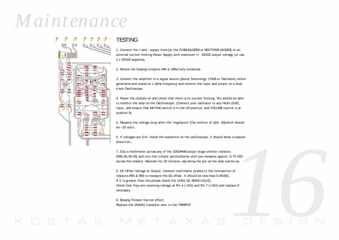
TESTING
1. Connect the + and - supply lines [at the FUSEHOLDERS or RECTIFIER DIODES] to anexternal current limiting Power Supply with maximum +/- 30VDC output voltage (or use2 x 30VDC supplies).
2. Rotate the biasing trimpots VR5 & VR5a fully clockwise.
3. Connect the amplifier to a signal source (Sound Technology 1700B or Oscillator) whichgenerates sine waves at 1.0kHz frequency and monitor the input and output on a dualtrace Oscilloscope.
4. Power the module on and check that there is no current limiting. You should be ableto monitor the amp on the Oscilloscope. (Connect your oscillator to any HIGH LEVELinput, and ensure that MUTING switch is in the UP position, and VOLUME control is atposition 9).
5. Measure the voltage drop after the "regulators" [the emitter of Q16, 30]which shouldbe ~20 volts .
6. If voltages are O.K. check the waveform on the oscilloscope, it should show crossoverdistortion.,
7. Clip a multimeter across any of the 100OHMS output stage emitter resistors[R46,56,55,45] and turn the trimpot anticlockwise until you measure approx. 0.75 VDCacross this resistor. Maintain for 30 minutes, adjusting the pot as the amp warms up.
5. DC Offset Voltage at Output. Connect multimeter probes to the intersection of resistors R55 & R56 to measure the DC offset. It should be less than 0.05VDC. If it is greater than this please check the LF351 DC SERVO IC[U1]. Check that they are receiving voltage at Pin 4 (-15V) and Pin 7 (+15V) and replace ifnecessary.
6. Biasing Trimpot has not effect.Replace the 2N4401 transistor next to the TRIMPOT.

K O S T A S M E T A X A S D E S I G N
M a i n t e n a n c e
17

K O S T A S M E T A X A S D E S I G N
S c h e m a t i c
Q10
R21 R22
R24 R25
R13
R19
R28
R29
R12R11
R18R17
R45
R10R9
R16R15
R46
R26
R27
R14
R20
R23
R4
R73
R8
R2
R3
R1
R6
R5
R7
VR5
D1
D2
R30
R313
26
1 5
74
U1
Q2
Q4
Q3
C3 C6
C7
C8
C5
C1
C2
R35
R55
R56
R75
R74
C13
1
2
3
Q14
1
2
3
Q15
Q9
Q11
Q5
Q6
Q7
Q8
Q1
C4
OUT_L
R42
R38
R36
1
2
3Q33
C9
R41
1
2
3Q34
C10
Q17
Q29
1
2
3Q16
1
2
3Q30
R102
R103
R101
R108
R119
R100
R109
R106
CE9
CE10
DZ1
3
26
1 85
74
U4
3
26
1 587
4
U5
ZD1
C20
C25
R50
18

K O S T A S M E T A X A S D E S I G N19
E C D e c l a r a t i o n o f C o n f o r m i t y
t o A p p r o p r i a t e S t a n d a r d s
S a f e t y
HD 195-S6
EN 60 065
E M C
Emissions Tested to EN 55013
Sound and television broadcast
receivers and associated equiment
Immunity Tested to EN55020
Electromagnetic immunity of
broadcast receivers and associated equipment
In accordance with
CISPR 16-1
Radio disturbance and immunity measuring apparatus
CISPR 16-2
Methods of measurement of
disturbances and immunity
IEC 801-2 )
IEC 801-3 3V/m 20dB
IEC 801-4 1KV (AC lines)
M a n u f a c t u r e rMetaxas Audio Systems1460 Woodend RdRomsey 3434Victoria [email protected]:+613992 36481
P r o d u c tMetaxas Charisma Preamplifier

K O S T A S M E T A X A S D E S I G N
D e s i g n P h i l o s o p h y
20