charles / mgh station - cdn.mbta.com · option b2.0 new station at enlarged cambridge street island...
TRANSCRIPT

CHARLES/MGH STATION Design Summary Report
1
CHARLES / MGH STCHARLES / MGH STCHARLES / MGH STCHARLES / MGH STCHARLES / MGH STAAAAATIONTIONTIONTIONTION
Massachusetts Bay Transpor tation Authority ProjectC h a r l e s / M G H R e d Li n e S t a t i o n A c c e s s i b i l i t y a n d M o d e r n i z a t i o n
Design Summary Report
E L K U S M A N F R E D IA R C H I T E C T S L T DAugust 31, 2000

CHARLES/MGH STATION Design Summary Report
2

CHARLES/MGH STATION Design Summary Report
3
4
7
9
11
13
26
27
29
30
55
63
64
Executive Summary
Background
Project Goals
Design Competition
Existing Conditions
Local Area Developments
Traffic Options Methodology
Station Location Methodology
Project Options / Potential Alternatives
Development of Three Options
Conclusion
Index
Table of Contents

CHARLES/MGH STATION Design Summary Report
4
Elkus / Manfredi Architects Ltd – HDR, A Joint Ven-ture Team, is pleased to present in this draft “DesignSummary Report” the conclusions of a five-monthstudy of the Charles/MGH Red Line Station. Projectgoals are to make the station ADA compliant, accom-plish safe pedestrian, barrier-free access to the sta-tion and platforms, modernize the station to be cus-tomer friendly, operate optimally, portray an appropri-ate image as a gateway to Cambridge/Boston andconsider the future development of MassachusettsGeneral Hospital.
Information Gathering
Preliminary information gathering led to the review ofarchival drawings of the Longfellow Bridge, theCharles Circle MDC roadway, viaduct construction,original station construction and subsequent improve-ment drawings, including the platform extension in the1980’s. Team members and consultants met on sitefor a preliminary assessment of the existing conditionof the station, structure, piers and viaduct, track, sig-nals and power. The MBTA hosted a presentation ofthe “ideas” competition, held in 1998 to generatecommunity input for a renewed Charles/MGH station.
Urban Context
Presented in its context, the station can be consid-ered at regional, neighborhood and station districtscales. As a regional facility, Charles/MGH stationacts as an entry or “gateway” from Cambridge toBoston, a destination for highly visible Esplanadeevents, a transportation key station, particularly, to
Executive Summary
world-renowned medical institutions. While the sta-tion punctuates the landmark Longfellow Bridge, manypedestrians also walk past the station while enjoyingthe Esplanade, and Harborwalk.
At the neighborhood scale, Charles/MGH is withinwalking distance, not only, of Beacon Hill, but also, ofCharlesbank, City Hall, the Boston Common and thePublic Garden. The station district encompasses thecommercial areas of Cambridge Street, institutionaluses, mostly to the north and the dense residentialdistrict of Beacon Hill.
Pedestrian / Vehicular Circulation
Investigations of traffic and pedestrian circulation atthe station and Charles Circle revealed significantconflicts. The project team undertook traffic model-ing of existing conditions, pedestrian origin and desti-nation surveys, and automatic traffic recorder countsto verify and confirm visual observations.
Meetings / Dialogue
Meetings with the MBTA partners, MDC, MGH, MEEI,BRA and BTD, were held regularly to create a dia-logue over the past, present and future developmentsaround Charles/MGH Station. The partners lend arealistic outlook to the process, while representingtheir interests. Two public meetings were advertisedand held at the Shriner’s Burn Institute, on BlossomStreet. The first held on March 13, 2000, introducedthe project team, who presented a general analysis ofthe project area. Traffic and station access prefer-
ences, such as underground, at-grade, or above grade,were examined. By the second public meeting, heldon May 9, 2000, the team was able to present stationvariations discovered in the analysis.In September a third public meeting is planned toreview the selected station option with the neighbor-ing community. At this meeting the furture public re-view process will be discussed and general projectmilestone dates will be reviewed.
Project Alternatives
Station options ranged from a new or rehabbed sta-tion at the existing site, a new station sited on a newlydefined island created by modifying roadways, and anew station sited on an empty lot below the existingviaduct at the corner of West Cedar Street and LindallPlace. All were considered with varying circulationelements - underground, at-grade or above-gradepedestrian bridges.
Options
From the options, three were selected for further study:
� Option A1.2, Major rehabilitation to station at ex-isting location with pedestrian bridge access
� Option B2.0 New station at enlarged CambridgeStreet island with at-grade access
� Option C1.2 New station at West Cedar Streetwith bridge access to MGH/MEEI district area

CHARLES/MGH STATION Design Summary Report
5
� Expanded program areas increase safety andfunction during events
� Roadway changes required to develop station siteprovide a more functional intersection
� Ease of construction and phasing allows existingstation to remain unaffected during most of con-struction process
� High value of improvement for money spent
Option C1.2 New station at West Cedar Street withbridge access to MGH/MEEI district area
Option C is presented as an opportunity to completethe Cambridge Street edge by siting the station onthe lot where the elevated Red Line tracks cut throughfrom Cambridge Street towards the portal. A new sta-tion addresses neighborhood context and solves pe-destrian access to the station.
� Infills street frontage at Cambridge Street
� Improves security at West Cedar Street as a pub-lic function – reduces homeless gathering space
� Retail areas complete street frontage
� Possible pedestrian bridge connection to MGH’sfuture campus entry
� Station is part of Beacon Hill, not an island in theintersection
Option A1.2, Major rehabilitation to station at exist-ing location with pedestrian bridge access
Option A is a redesign of the station on the existingsite, approached from the perimeter of Charles Circlefrom new headhouses at the north and south sides.New glass enclosed, truss-type pedestrian bridges,connect to the existing mezzanine level, where the payplaza is located.
� New version of the old station has many of thesame functional problems as the existing station
� Difficult to phase and construct
� Value for the dollar spent is low
� Program areas remain cramped due to site andtrack structure limits
Option B2.0 New station at enlarged CambridgeStreet Island with at-grade access
Option B considers a redesigned traffic scheme forCharles Circle as its starting point. By revising trafficpatterns, an enlarged “island” can be carved out, cre-ating an at-grade pedestrian crossing to the stationheadhouse.
� At-grade access to station greatly improves pe-destrian understanding of the station
� Links station to neighborhood
� Improves security and user-friendliness
� Future traffic changes easier without station inintersection
� Total costs exceed project budget
Conclusion
While all three options selected for additional consid-eration satisfy the project goals, they, nonetheless,have different costs, values, schedules and phasingconcerns. The Design Report is intended to be usedas a starting point for additional dialogue among allparticipants, the MBTA, the partners, and the commu-nity, leading to a consensus for proceeding with thenew Charles/MGH Station.
Elkus / Manfredi Architects Ltd – HDR, A Joint Ven-ture Team, recommends Option B2.0 New station atenlarged Cambridge Street Island with at-grade ac-cess - as the best solution of the options. This optionhas the highest value for the cost. It will be the easi-est to construct, and it will be the least disruptive totransportation services for the T to build.

CHARLES/MGH STATION Design Summary Report
6
CHARLES/MGH STATION Design Summary Report
71
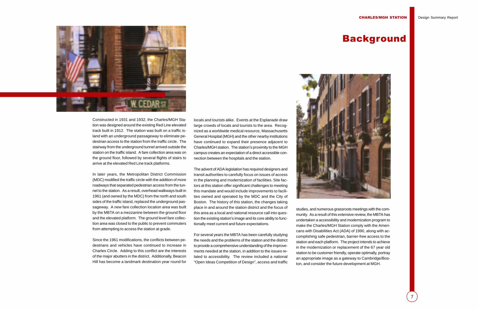
Constructed in 1931 and 1932, the Charles/MGH Sta-tion was designed around the existing Red Line elevatedtrack built in 1912. The station was built on a traffic is-land with an underground passageway to eliminate pe-destrian access to the station from the traffic circle. Thestairway from the underground tunnel arrived outside thestation on the traffic island. A fare collection area was onthe ground floor, followed by several flights of stairs toarrive at the elevated Red Line track platforms.
In later years, the Metropolitan District Commission(MDC) modified the traffic circle with the addition of moreroadways that separated pedestrian access from the tun-nel to the station. As a result, overhead walkways built in1961 (and owned by the MDC) from the north and southsides of the traffic island, replaced the underground pas-sageway. A new fare collection location area was builtby the MBTA on a mezzanine between the ground floorand the elevated platform. The ground level fare collec-tion area was closed to the public to prevent commutersfrom attempting to access the station at grade.
Since the 1961 modifications, the conflicts between pe-destrians and vehicles have continued to increase inCharles Circle. Adding to this conflict are the interestsof the major abutters in the district. Additionally, BeaconHill has become a landmark destination year round for
locals and tourists alike. Events at the Esplanade drawlarge crowds of locals and tourists to the area. Recog-nized as a worldwide medical resource, MassachusettsGeneral Hospital (MGH) and the other nearby institutionshave continued to expand their presence adjacent toCharles/MGH station. The station’s proximity to the MGHcampus creates an expectation of a direct accessible con-nection between the hospitals and the station.
The advent of ADA legislation has required designers andtransit authorities to carefully focus on issues of accessin the planning and modernization of facilities. Site fac-tors at this station offer significant challenges to meetingthis mandate and would include improvements to facili-ties owned and operated by the MDC and the City ofBoston. The history of this station, the changes takingplace in and around the station district and the focus ofthis area as a local and national resource call into ques-tion the existing station’s image and its core ability to func-tionally meet current and future expectations.
For several years the MBTA has been carefully studyingthe needs and the problems of the station and the districtto provide a comprehensive understanding of the improve-ments needed at the station, in addition to the issues re-lated to accessibility. The review included a national“Open Ideas Competition of Design”, access and traffic
Background
studies, and numerous grassroots meetings with the com-munity. As a result of this extensive review, the MBTA hasundertaken a accessibility and modernization program tomake the Charles/MGH Station comply with the Ameri-cans with Disabilities Act (ADA) of 1990, along with ac-complishing safe pedestrian, barrier-free access to thestation and each platform. The project intends to achievein the modernization or replacement of the 67 year oldstation to be customer friendly, operate optimally, portrayan appropriate image as a gateway to Cambridge/Bos-ton, and consider the future development at MGH.

CHARLES/MGH STATION Design Summary Report
8

CHARLES/MGH STATION Design Summary Report
9
The purpose of this report is to review the major issuesinvolved in determining the final concept for achieving thesegoals and improving the station and the station district.
This comprehensive evaluation and modernization of theCharles/MGH Station offers a unique opportunity to re-define this gateway to the City of Boston. The CharlesStation district which has suffered from several decadesof neglect now looks forward to development of the his-toric Charles Street Jail, the expansion and renovation ofthe MGH/MEEI campus, major public and governmentalprojects on Cambridge Street, and a civic rededication tothe Charles River Basin. Recognizing the importance ofthe station to the district, the MBTA has established adialog with all members of the community for a completeperspective of project goals and objectives.
ADA Access Compliance
In late 1989 and early 1990s, the Massachusetts BayTransportation Authority (MBTA) developed an approvedKey Station Plan as a first step in carrying out its obliga-tions under the Americans with Disabilities Act of 1990(ADA). ADA, Title II-Public Services, requires public trans-portation systems not to discriminate against persons withdisabilities.
The Federal Transit Administration rule establishes thespecific requirements for developing a key station plan,which include working with the community of people whohave disabilities to determine key stations, based on listedcriteria, as well as system-wide program accessibility.
The American with Disabilities Act of 1990 also includedaccessibility guidelines (ADAAG) for the design of trans-portation so that they are usable by people with disabili-ties. The guidelines, in conjunction with current State Ac-cess Board Regulations, cite the need for accessibleroutes to and from accessible entrances to stations and
boarding platforms used by the public. The accessiblepaths should coincide with the path used by the generalpublic. Elements for future connections should also beon an accessible route.
The resulting design changes inspired by compliance withthe ADA mandate has increased the general accessibility oftransit structures to a broad range of the traveling public.
Ramps and elevators are as welcome to families withstrollers as they are to chair-bound individuals.
Presently, Charles/MGH Station is not in compliance withthe minimum requirements of ADAAG or the Massachu-setts Architectural Access Board; it is not possible toreach the station, nor the platform level, without walkingup and down numerous flights of steps. No elevators orescalators are provided. The redesign of Charles/MGHStation will provide an accessible route to an accessibleentrance for public use of the trait system.
Community and Abutter Goals
The Charles/MGH Station area comprises a number ofdifferent user communities broadly described as the RedLine commuters, the residents and businesses of Bea-con Hill, the hospital district, the occupants of CharlesRiver Park, the users of the Esplanade, and the generalpublic of the metropolitan area at large.
Each group has a priority list of features they would liketo see in the development of the station and the CharlesCircle environs. The common goals of these groups aresimilar: improved pedestrian access and accessibility,reductions to traffic congestion, a more attractive andsecure sidewalk environment, and a Red Line station fa-cility that contributes in a positive manner to the generalarea. The MBTA’s continuing dialogue with these groupshas helped to clarify their interests and concerns as well
Project Goals
CHARLES/MGH STATION Design Summary Report
10
as identify opportunities for additional improvements in theCharles Station district.
The Beacon Hill community has a longer list of issues re-lated to the station, including train noise and vibration, secu-rity of the areas adjacent to the station, pedestrian accessacross Cambridge Street and to the Esplanade, and the ur-ban fit of the station with the fabric of the historic district.With the establishment of the National Historic District, thiscommunity has recognized the fragile nature of this nationaltreasure and has labored to maintain and preserve it for thefuture.
The Beacon Hill business community would like a stationthat completes the special retail character of Charles Streetand welcomes both residents and visitors to the district. Theyhope that the new station design will mark the end of CharlesStreet in a manner that will compliment the district.
MGH and MEEI have experienced changes in medical carewhich have increased the outpatient component of hospitalservices. To meet these changing needs the hospital districtmust provide its patients with a barrier-free path from thestation to the hospital campus. MGH would like to blend astation access point into their proposed development alongCambridge Street. This access point can take on many forms,but should reflect the visual and security goals of the hospi-tal community.
Residents of Charles River Park would concur with the goalsof the hospital and agree with the noise and security issuesraised by the Beacon Hill community. With a goal of betterintegration of their community with the rest of the district,pedestrian access across Cambridge Street and to the Es-planade is a baseline issue to this group.
Users of the Esplanade vary in their relationship to the sta-tion. Those that arrive by the Red Line require barrier-freeaccess from the station to the Esplanade ramps. They also
require the station to accommodate special event crowdssafely, and provide clear passage and directions to concerts,celebrations, and events. Charles Circle, a major intersec-tion, connecting pedestrian traffic from the LongfellowBridge/Esplanade, Beacon Hill and the hospital district; re-grettably, barely provides for safe access. Since the stationis located within the intersection, the design of the stationshould incorporate improvements for pedestrian activitiesin order to functionally address the needs of all user groups.
Above Ground Station
The Charles/MGH Station travelers have endured years ofdifficult station access and substandard station facilities. Thephysical design of the station with its limited access, has anegative impact on the expanded use of this station by com-muters. Combined with access issues are the basic prob-lems of above ground stations. Commuters are exposed tomore severe weather conditions on unprotected elevatedplatforms, lack of visual connections to points of security(i.e. the “eyes of the street,” MBTA staff), and the generallack of urban fit of the station with the surrounding district.The proposed modifications to Charles/MGH should try tosolve as many of these issues within the given envelope ofan above ground station.
Agency Review
There are a number of state and local agencies with whomthe MBTA has established a technical advisory committeeto assist in the development of this project. The MDC, Cityof Boston, including Boston Transportation Department andthe Boston Redevelopment Authority, Massachusetts His-torical Commission and Boston Landmarks Commissionhave been part of the development of the design alterna-tives identified in this report. The location of this station, theseparate ownership of the pedestrian bridges to the station,
and the various projects ongoing in the station district sug-gest that cooperation and coordination among the appro-priate agencies will result in a comprehensive improvementprogram that will go well beyond the goal of accessibility.
MBTA Project Goals
As clearly stated in the MBTA project description, the pri-mary goal of station accessibility and modernization atCharles/MGH is to meet the federally mandated key stationplan objectives of accessibility to all those with disabilitiesby December 31, 2003. Additionally, the MBTA has de-scribed a broader list of objectives including:
� Provide links to the new development at the CharlesStreet Jail site and the recreational areas of the CharlesRiver Basin
� Develop an architectural expression appropriate as agateway image to Boston/Cambridge
� Design a station and platform enclosure that provides alevel of patron comfort and protection from the elements
� Reduce train noise and vibration
� Minimize service disruptions during construction
� Improve pedestrian and vehicle safety at Charles Circle
� Incorporate public art into the station design reflectingthe history of the district

CHARLES/MGH STATION Design Summary Report
11
In 1998 the MBTA and Partners Healthcare, Inc. (Massa-chusetts General Hospital) conducted an “Open IdeasCompetition of Design” for the Charles/MGH Station. Thepurpose of this competition was to solicit ideas for thetransformation of the Charles Circle area in general andthe Charles/MGH Station in particular into an accessibleand welcoming gateway to the neighboring communitiesand institutions. The ideas competition provided an open-ness to examine the area without restrictions, and pro-vides the creative forum for originality and quality civicdesign. Some of their major goals were:
� Accomplish safe, barrier-free pedestrian access to thestation and to each platform
� Increase public awareness of the project and theproject’s inherent complexity
� Develop a shared vision of the development of the sta-tion district with the community and the institutionalneighbors
� Enhance the gateway/public place recognition of thesite
� Test the ability of the station to connect various useswithin the district
� Explore architectural expressions for the station,headhouse and the surrounding district
� Visualize the impact and urban possibilities of barrier-free access to the station and across the intersection
The process commenced on August 3, 1998, and con-cluded nine weeks later – on October 2, 1998. The sub-mission requirement was a simple: one 24” x 36” board.
A mailing of the brochure was sent to approximately 3600architects and 100 Schools of Architecture nationally.Advertisements were run in the local newspapers, andthe MBTA displayed 200 “car cards” in the Red Line trainsand within the Charles/MGH station. A website was cre-ated to publicize the competition and also linked to localand national architectural societies. A total of 355 peoplepicked up packets of information, and 133 submitted finalideas.
The judging was intense. The process was photographedand videotaped for publicity and education purposes. Eachround concluded with “passionate” discussion and rea-sons for including certain boards in the next round. Thejudges decided that since it was truly an “Open Ideas Com-petition of Design” that there was not just one good idea,but several and decided to award five First Awards withmonetary price of $4,300, six honorable mentions with aprize of $1,000 each and five citations of $500 each.
The range of ideas were many but could be categorizedinto realistic, buildable projects. Some reused the old sta-tion, extended it further to create new pedestrian friendlyentrances closer to the residential street, and others werecompletely futuristic with a “media” platz and projectionof new technologies on the screen on the walls of thenewly constructed station as if it were a stage. Otherscombined other levels of activities into the modern stationsuch as a day-care facility, a casual juice-bar meeting place,exhibit space, gallery walkways. The jury did look for thebold architectural gestures.
This new design initiative has fostered public/private part-nership not only in the financial commitment to the designcompetition and the participation in the process, but alsoin the financial investment in the future construction project.
Design Competition
Competition Winners
First Awards
1 Maria Aiolova, Alexander Chouls, Tunch Gungor
2 Charles P. Hagenah
3 Robert Marks
4 Thomas Melville
5 Arturo Vasquez
Honorable Mentions
1 Eric Belson, Max Drivin, Michelle Ho, Anna Kuperman,Elliott Paul Rothman, Gabriel Yaari
2 Matthew Hyatt, Angela Ward Hyatt
3 Branka Milosevic
4 Michael O’Keefe, Belinda Watt
5 Jessica P. M. Pineo
6 Stephen Rose
Citations
1 Steven Beaucher, Paul Lukez
2 Jennifer Davy, Rolando Mendoza, Keith Nelson
3 Keith Engel
4 Susan Hoadley, William Massey
5 Kristen, Mary Turner, Tara

CHARLES/MGH STATION Design Summary Report
12
A
D
C
B
A First Award (Shared) – Robert Marks
This entry moved the headhouse to the east with “walkback” connections to the existing platforms. The relo-cated station solves the hard urban site edge at WestCedar Street by wrapping the rail structure and com-pleting the urban street line with the headhouse.
B First Award (Shared) – Thomas Melville
Located on the easterly traffic island and connectedto either side of the intersection by tunnels, thisscheme explored the gateway image potential of thesite. Using “new millennium” themes, the station actsas a giant billboard, locating the urban place in a man-ner similar to the CITGO sign at Kenmore Square.
C First Award (Shared) – Maria Aiolova
Alexander Chouls
Tunch Gungor
“Metromedia platz” covers the intersection with anurban berm, connecting the neighbors of the district.On this “common ground” berm, it appears that allmanner of possibilities can appear before your eyes –an architectural equivalent of virtual reality!
D Honorable Mention – Branka Milosevic
By making minor changes to the easterly traffic islandand intersection roadway geometry, this proposalclearly solves the access issues to the station withinthe existing perimeters. Clever additions of drop offlanes, plantings, and curb adjustments show a realeffort to take this urban space to another level. Thebold maneuver in this option is the development of a
Competition board photographs courtesy ofPhil DeJoseph, MBTA Photographer

CHARLES/MGH STATION Design Summary Report
13
History of Charles/MGH Station
The Charles Street/MGH Station is included in theInventory of Historic and Archaeological Assets of theCommonwealth. The station was completed in 1932for the Boston Elevated Railway Company accordingto plans prepared by Boston architect R. ClipstonSturgis. The station is composed of a multi-story en-trance building of cast stone and passenger platformsenclosed by copper-clad windscreens. The entrancebuilding has a rusticated base above which smoothfinished concrete is articulated on the north and southelevations by center pavilions and pilasters withmolded capstones. The Art Moderne style of the build-ing is further reinforced by long double casement win-dows, a chevron panel, and long window openingsflanking the central opening.
The station is located outside the boundaries of theBeacon Hill Historic District; however, the portal build-ing and a portion of the elevated track are within thebounds of the historic district. The Beacon Hill His-toric District is listed in the State and National Regis-ters of Historic Places, in addition to being a NationalHistoric Landmark and Boston Historic District. Thestation is within the boundaries of the Charles RiverBasin Historic District, which is listed in the State and
National Registers of Historic Places. The LongfellowBridge, which is adjacent to the project site, is a con-tributing element in the historic district. Although theCharles Street/MGH Station is within the bounds ofthe district, it is not apparent from a review of theNational Register nomination for the Charles RiverBasin district if the station is considered contributingto the historic district.
The station is also located across Cambridge Street/Charles Street from the Suffolk County Jail (a.k.a.Charles Street Jail), which is individually listed in theState and National Registers of Historic Places.
The station has experienced various alterations andchanges since its original construction that have com-promised its appearance and architectural integrity.At some point the cast stone classical balustrade thatsurrounded the traffic circle was removed and the origi-nal sidewalk pattern changed. In the 1960’s largeopenings were cut into the second floor level on thenorth and south elevations to accommodate a newelevated walkway and stair system. Also during thisperiod the interior was completely rearranged and theunderground passageway closed.
Existing Conditions
Charles Street Jail

CHARLES/MGH STATION Design Summary Report
14
Architectural Condition
After 68 years of use, Charles/MGH Station is in needof major repairs or replacement. The station consistsof a three-story headhouse, located at one end of 424-feet-long platforms. The outboard platforms are opento the weather, although canted roofs provide someshelter. Above-grade pedestrian bridges from twodirections connect to either side of the station, atmezzanine level. The station building is 42 feet widex 70 feet long, having approximately 2,940 square feetin area at ground and mezzanine levels. At platform
Grade Level
Originally accessed at grade in a center island, theground floor of the station is now abandoned, exceptfor utilities and employee rest room facilities. On oc-casion, pedestrians, searching for a way into the sta-tion, cross Charles Circle at grade, and use one ofthe lower entrances, although the doors are clearlymarked, “Not An Entrance.” Two steel stairs lead upto mezzanine level from the ground floor. Walls ofpainted glazed brick are peeling throughout. Floorsare unpainted concrete. Standing water was noted
Mezzanine Level
The mezzanine, added to the original station in 1961,is tucked into what was formerly a double-heightspace. The space is built out with minimum headroom,tucked under the deep track girders above. Ceilingheight is only about 7’-6”. Now, the mezzanine servesas the entrance and exit level to the station, reachedfrom the two remote sets of stairs and bridges: oneon the Beacon Hill side, the other on the Charles StreetJail/MGH side. About 50 percent of the station trafficis by pedestrians, who wish only to cross Charles
level, the station is bisected by the elevated track struc-ture, creating openings at either end of the building.
Constructed of highly detailed cast stone base, walls,pilasters, and friezes, the building exterior is seriouslydeteriorating. Major spalling of decorative elements,including cracked lintels above pedestrian walkways,and grade level doors, cracks at the underside of thebridge connections and the track girders are all evident.Vertical cracks at pilasters, corner quoins and windowsindicate critical levels of damage. The cast stone cor-ner at the northwest is separating from the structure.Cracks and missing sections of concrete bases in thefreestanding columns supporting the pedestrian bridgesare also evident.
At-grade steel door frames with fixed panels are rustedout at their bases, while the doors themselves, alumi-num with polycarbonate glazing, are relatively intact.Rusting of the replacement exterior metal window is alsooccurring from moisture penetration within the walls.
on the ground floor, which appears to have enteredthrough open windows above. Continuing water infil-tration has seemingly caused old, rust-stained plasterto loosen and fall to the floor. The ceiling, wall andcolumn surfaces throughout are peeling and deterio-rating.
Lighting throughout the station consists of vandal-re-sistant fluorescent fixtures, which are in good condi-tion. The fire alarm annunciator panel is located nearthe exterior doors and appears new. Additional elec-trical and fire alarm panels are housed in a lockedroom at grade level. The station does not have a me-chanical system.
Circle safely. They pass through this level from oneside to the other, without using the subway system.Consequently, this level receives more traffic than justthe T ridership and feels cramped and undersized.Adding to this problem are the fare collection booth,signage, turnstiles, gates and public telephones, com-peting for space at the same level.
Mezzanine level is finished with rubber flooringthroughout, which is in poor condition. Corrugatedmetal panels act as separation walls between this floorand ground floor. Openings in the corrugated panelsare fitted with large fans, presumably for summer cool-ing. Vibration and noise is extremely exaggeratedthrough this material, when trains travel through over-head, shaking the panels. The brick walls are painted,and look fresh. Ceilings are painted, cofferred con-crete set between the track girders. Lighting is fluo-rescent, new in appearance, having been installed bythe MBTA in 1997.
South facade of station Northwest corner of headhouse Drain box Electric panel

CHARLES/MGH STATION Design Summary Report
15
Stairs, which lead up to either platform, have blindspots midway up. Users are frequently turning thecorner and bumping into someone coming from theopposite direction. Rubber stair treads and landingsare deteriorated and missing, while metal risers arerusted and require refinishing. Stainless steel hand-rails on either side and in the middle are intact, al-though these do not appear to meet present buildingcode requirements.
Platform Level Enclosure
The building enclosure at platform level consists ofglazed yellow brick, cast stone window surrounds andmetal-framed windows. Chips and cracks in the brickand severely spalled precast elements are obvious.The metal-framed windows appear to be replace-ments, which are operable, however, some have beenpermanently fixed closed. Glass in the replacementwindows is polycarbonate, fogged and opaque inplaces. Fluorescent light fixtures supplement incan-descent can lights over the stairways. Some fixturesare newer than others; some are simply bare fluores-
cent tubes. The light levels are minimum at best, withsome improvement where newer fixtures are installed.The large old can lights, some missing lamps, are notproviding significant lighting.
Platforms
The original platform was extended in 1982 to the westtoward the Longfellow Bridge. Unlike the original cop-per clad platform walls, the extension sides are steel barfencing, separating the platform from the roadway be-low. The fencing, which incorporates pole mounted lightfixtures, appears to be in good condition, requiring sometouch up painting. The copper cladding on the exteriorof the original platforms, weathered to a green color, isdamaged on both sides at the base, where bent andtorn away sections appear to have been hit by vehicles.The copper could be repaired. Freestanding steel col-umns support the platform perimeter as it extends upthe Longfellow Bridge The underside of the platform isopen to the roadway below, separated only by diamondmesh fencing, whereas the platform underside at thenewer section is vertical concrete construction.
Painted concrete floors make up the platform. Spalled,pitted and broken up areas mar the platforms, par-ticularly at expansion joints, presenting a potential trip-ping hazard. Some concrete patching is apparent.Newer yellow textured detectable warning strips areinstalled at the platform edge. The platform sidewallsare vertical metal panels, with opaque polycarbonatefixed windows, centered between steel columns. Thewindows, fogged and defaced, are small squares. Withpotentially great views in all directions from the plat-form, the window size and placement disappoint, limit-ing the perspective. Wall finishes are severelyalligatored and peeling. Columns need to be refin-ished, having rust apparent, particularly at the base.The eastern end of the platform is separated from thetrack with black painted fencing. While the fencingitself is in fair condition, there is a long crack in theconcrete beam at the north platform where it ismounted.
The platform roof consists of wood tongue and grooveplanks, supported on bent steel cants. Paint is peel-ing off with evidence of severe water penetration inspecific roof areas. Roof leaders are noted at plat-form corners only. Strip fluorescent light fixtures aremounted between roof bents, some newer than oth-ers. Public address speakers are mounted on the roofedge, however, no equivalent information systems,such as reader boards, are installed. Convenienceoutlets are noted. Audio-visual fire alarm devices ap-pear relatively up to date.
Pedestrian Bridges
Two elevated bridge structures tie the station to ei-ther side of the roadway, one terminating at the side-walk adjacent to the Charles Street Jail’s enclosedprison yard, the other splitting and terminating at op-posite sides of Charles Street. Identical in structure,the pedestrian bridges are designed with fourteen footclearance over the roadways. Structural beams un-
View from platform towards Boston Example of platform roof deteriorationViaduct at headhouse
CHARLES/MGH STATION Design Summary Report
16
der the concrete slab add height to the vertical climbover the roadway, elevating the pedestrian bridgeseven further above the mezzanine level. Multiple stairruns lead from the sidewalk up to straight walkways.Both pedestrian bridges terminate short of the sta-tion with a short flight of stairs running down tomezzanine level, approximately seven and a half feetbelow. From there, a user must ascend to platformlevel, about 15 feet up. The bridges offer a safe, al-beit lengthy passage to the station. Even some able-bodied passengers are unable to use the station, be-
The MGH pedestrian bridge, an enclosed structure,acts as a shelter for homeless people. Homeless indi-viduals, crouched in the corner, use the pedestrianbridge for shelter on a daily basis. The pedestrianbridge is built of painted steel posts, lower metal pan-els and upper polycarbonate glazed windows. Open-ings at top and bottom of its sidewalls drain the struc-ture. Concrete floors and a corrugated steel deckceiling complete the enclosure. Vandal resistant lightfixtures are mounted to the ceiling. Lighting is mini-
supported directly off of the large track girders. Thefloor construction is typically 3- or 4-inch concreteslabs reinforced with heavy welded wire fabric. Theroof is believed to be timber plank, supported on asteel frame.
The headhouse structure is in poor condition. Thereis water damage observable at interior steel columnsand beams, including severe rusting at the base ofseveral ground floor columns. There is spalling atsome of the concrete encased beams at the pay lobbyceiling. There are full height vertical cracks in themasonry walls in the stairwells, probably at columnlocations. The exterior stonework is extensivelycracked on all facades. Several lintels are de-lami-nating, with the stonework above them entirely spalledaway. The pedestrian bridge attachments have causedsevere distress to the headhouse, including masonryapparently pulling away from the building and defor-mation of steel lintels below the bridge doorways.
The exterior walls are 12-inch-thick solid masonry andsit on the perimeter grade beams. Steel members arebuilt into the masonry at each floor level. Although athorough seismic analysis of the building would berequired, it can be said that the existing unreinforcedmasonry is not an ideal material for resisting seismicevents.
The Platforms
The platform foundations consist of reinforced con-crete footings in some cases, are supported on theexisting track and station girders. Also, at the westend, the platform is built directly on grade over theretaining walls built for the tracks.
The 9-foot-wide section of the platform sits on thebridge abutment at the track side and on steel col-umns at the outside. The roof is a built-up taperedcanopy beam, cantilevering off the column at the out-side wall. The platform slab is a 3-inch reinforcedconcrete carried on small steel beam running parallelto the track. The roof is wooden plank supported on
cause of the difficult pedestrian routes, up and downstairs. Elderly or physically impaired users are unableto use the station, lacking an accessible route. Bothbridges are approximately 5’-6” wide, ample enoughin width to allow only single file passage in either di-rection.
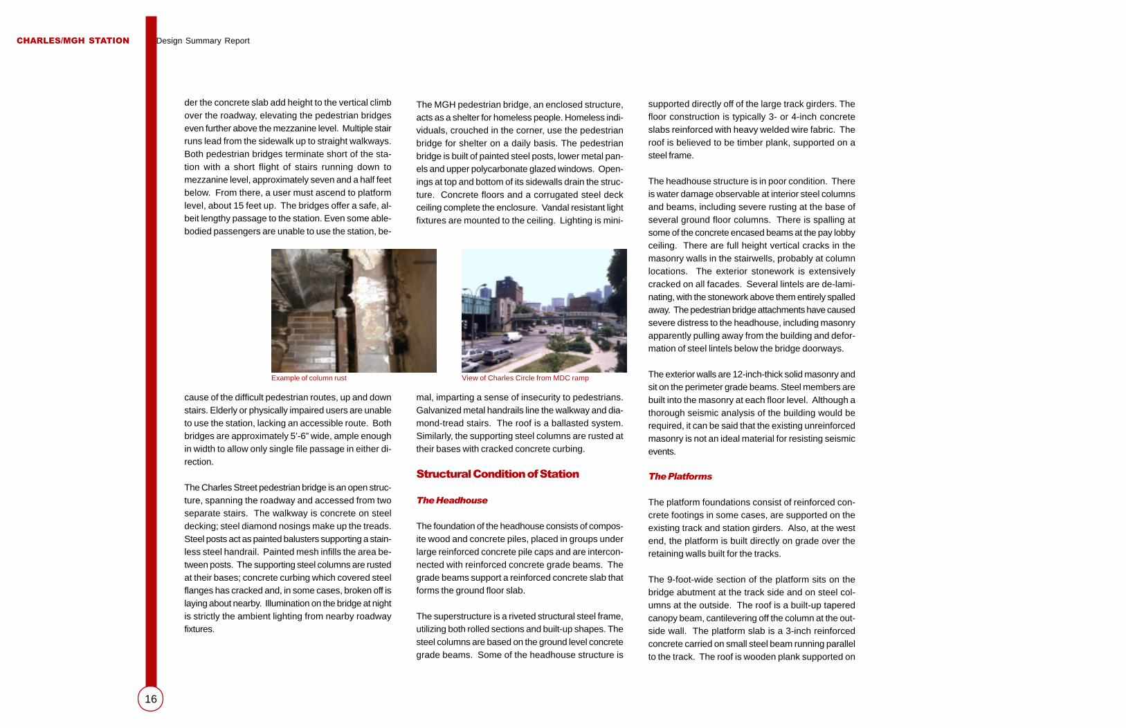
The Charles Street pedestrian bridge is an open struc-ture, spanning the roadway and accessed from twoseparate stairs. The walkway is concrete on steeldecking; steel diamond nosings make up the treads.Steel posts act as painted balusters supporting a stain-less steel handrail. Painted mesh infills the area be-tween posts. The supporting steel columns are rustedat their bases; concrete curbing which covered steelflanges has cracked and, in some cases, broken off islaying about nearby. Illumination on the bridge at nightis strictly the ambient lighting from nearby roadwayfixtures.
Example of column rust View of Charles Circle from MDC ramp
mal, imparting a sense of insecurity to pedestrians.Galvanized metal handrails line the walkway and dia-mond-tread stairs. The roof is a ballasted system.Similarly, the supporting steel columns are rusted attheir bases with cracked concrete curbing.
Structural Condition of Station
The Headhouse
The foundation of the headhouse consists of compos-ite wood and concrete piles, placed in groups underlarge reinforced concrete pile caps and are intercon-nected with reinforced concrete grade beams. Thegrade beams support a reinforced concrete slab thatforms the ground floor slab.
The superstructure is a riveted structural steel frame,utilizing both rolled sections and built-up shapes. Thesteel columns are based on the ground level concretegrade beams. Some of the headhouse structure is

CHARLES/MGH STATION Design Summary Report
17
Superstructure
In general, the superstructure is in fair condition. All ex-posed steel is in need of cleaning and painting.
� The topside of through girders in several spans con-tains areas of top flange cover plate impacted rust cor-rosion where the top cover plate has been bent up-ward. Through girders contain collision damage atseveral locations. Bitumen has been applied to thebottom five inches of the girder web and stiffeners inorder to protect the steel from corrosion. It appearsto be in fair condition.
� The undersides of through girders in several spanshave rust stains along the edges, particularly the cen-ter girder bottom coverplates, due to impacted rustcorrosion between the plates. The cover plates arewavy and curled at many locations, with separationsbetween plates.
� Stringers are in fair condition. The bottom flange edgesof stringers on several spans have been forced awayfrom the concrete deck, due to impacted rust betweenflanges and deck. The bottom flanges are transverselycupped because the edges have curled downward.
steel purlins. In the longitudinal direction, there is nolateral load resisting system. To meet current seismicstandards, some additional members would need tobe introduced to the platform structure.
The 12-foot-wide platform is supported entirely by the76-inch-deep main girder and the 42-inch-deep sta-tion girder. The floor beams sit on these two largegirders, and the column hangs off the side of the floorbeam and is braced to the bottom of the station girder.A built-up tapered cantilever off each column againframes the roof, with smaller purlins framing betweenthe bents. As with the narrower platform canopy, thereis no provision for lateral load in the long directionand therefore some additional bracing would be re-quired.
In general, the condition of the platform structure abovethe floor level appears to be good. A minimal amountof rust was observed, and there is a good deal of peel-ing paint, but generally the structure appears well main-tained.
Structural Condition of the Viaduct Structure
The Viaduct Structure, built by the Boston BridgeWorks in 1911, consists of eleven bridge spans andten intermediate piers that carry two Red Line RapidTransit tracks between the Beacon Hill Tunnel abut-ment and the Longfellow Bridge abutment in Boston.
Deck
Overall the deck is in fair condition, as follows:
� The ties and ballast are in satisfactory condition.The rail, track guard rail and rail fasteners are infair to good condition.
� Protective board, placed over the waterproofingmembrane, is typically curled and loose alongmost of the spans. Ballast and other debris haveaccumulated between the protective board andconcrete sidewalks. Deck joints are in fair condi-tion. The deck joints are uneven and completelyclosed in some areas. Efflorescence has accu-mulated on the underside of the decks at randomlocations throughout the structure and especiallynear the joints where heavy deposits are found.
� Concrete sidewalks are in poor condition. Thesidewalks show various degrees of deteriorationat many locations.
� Concrete drain boxes are in fair condition. Theconcrete drain boxes located over the piers haveevidence of cracks and spalls at several locations.The handrails are in fair condition. The handrailshave rust and pitting across some of their surface.
Viaduct and piersLongfellow Bridge eastbound traffic

CHARLES/MGH STATION Design Summary Report
18
Geotechnical
The upper soils consist of loose to medium densegranular fill soils, generally overlying soft organic soils.In most areas, the fill and organic soils are underlainby medium stiff to stiff silty clay (Boston Blue Clay).In some areas, a zone of medium dense to dense sandand gravel is present between the organic soils andthe clay. The clay is underlain by dense to very denseglacial till. In general, the till is directly underlain bybedrock consisting of argillite and sandstone. How-ever, conditions in the vicinity of Beacon Hill are quitevariable, and zones of clay and gravel as well as deepertill can underlie the upper till. The upper part of thebedrock, to depths varying as much as three feet, hasweathered to hard soil in many areas.
Timber piles bearing in the clay and sand below theorganic soils support the existing elevated track struc-ture. Piles supporting the existing Charles/MGH RedLine Station are composite timber/concrete piles,bearing in the clay and sand. The portions of the pilesbelow the groundwater level are timber and above thegroundwater level are concrete.
Substructure
The substructure is in fair condition. The Lindall Placeeast abutment, located near the Beacon Hill Tunnel,is generally in fair condition, with some narrow cracks,spalls, spall with rebar exposed and epoxy filled cracks.
The concrete piers range from fair condition with somecracks and minor spalls present to poor condition withextensive cracks, spall and spalls with rebar exposed.Some cracks located along the edges of the top capmoldings are typical to almost all piers
Piers with steel members are generally in fair condi-tion; the center transverse bent girder has localizedareas of heavy corrosion on the top flange, and theoutside transverse girders have heavily corroded bear-ing plates under the middle longitudinal stringer.
Overall, the Red Line viaduct structure is in fair condi-tion, requiring limited repair and preventive mainte-nance to upgrade the structure, as part of the overallstation redesign.
Environmental
Based on a review of the site history, the project areaappears to be typical of most urban areas. Due to thepresence of former gasoline stations, there is the po-tential of encountering soils and ground water con-taminated with Volative Organic Compound. It is alsolikely that soils excavated, as part of construction ofany selected alternative for station development willneed to be managed in accordance with the Massa-chusetts Contingency Plan.
In response to concerns from Beacon Hill arearesidents, the MBTA completed noise and vibrationstudies in 1999. These studies concluded thatnoise mitigation will improve conditions at the RedLine portal at Charles Circle. A priority ranking wasestablished for residential areas abutting the RedLine. This ranking was based on the relative valueof noise abatement treatments for those residentialareas. The resulting priority list then serves as aguideline for the MBTA in determining where toconsider noise abatements, with noise abatement forhighest-ranked locations considered first. Althoughnot directly part of the Charles/MGH accessibilityand modernization project, the MBTA has agreed toinclude noise mitigation at the portal into reconstruc-tion of the Charles/MGH Station.
Communications
A public address system of sorts exists at Charles/MGH Station. It consists of seven small, low qualityhorn-type speakers, all of which are mounted on theexisting overhead canopy which covers most of theoutbound platform except for the platform extensionwhich was added in 1982. These speakers are drivenby public address equipment mounted in an enclosedand locked public address rack housed in an equip-ment room located at the south end of the outboundplatform. This equipment is connected to the MBTA
Underside of viaduct Cambridge Street and Charles Streetintersection

CHARLES/MGH STATION Design Summary Report
19
Should pit rail switch B/A620 fail in any way or manner, itwould result in the deenergization of the pit rail. By closingnormally open switches 1 and 2 in switchbox J/A620 orswitches 3 and 4 in switchbox J/622, three 2,000 kcmilcables from each of the above mentioned switches whichterminate at the pit rail would be energized and, in turn,energize the pit rail.
Control Center at 45 High Street. The equipmentproduces low quality sound. There is also one horn-type speaker inside the existing CommunicationsRoom at the south end of the outbound platform.
There are three communication junction boxes (CJB’s)located on the west end of the outbound platform thatare in fair to poor condition. The cable entering andleaving the CJB’s also appears to be in fair to poorcondition. Under the inbound platform overhang, thereare two communication junction boxes. The cables inand out of these CJB’s are resting on the cover of atraction power manhole and will require some meansof support to get them off of the cover.
There is no electronic signage currently in place tocomply with ADA requirements at this station. Thereare visual fire alarms in place along both platforms.The fire alarm equipment is located in a street levelroom that also houses the Fire Department MasterBox that drives this equipment.
Signals
Currently, there isn’t a signal room at Charles/MGHStation. The Automatic Train Protection (ATP) equip-ment is controlled out of the Central Instrument Room(CIR) at Park Street. There is one wayside signal at-tached to the wall on the inbound track, just east ofthe existing platform. At each end of the station onboth tracks there are high frequency impedancebonds which transmit speed control commands to thetrains via the running rails. There are six train approach(TAK) lights, attached to the structure walls betweenthe station platform and the Park Street portal.
Traction Power
Inbound Platform
The condition of the 1,000 and 2,000 kcmil in andout of pit rail switch 2 in switchbox B/A620 appearsto be in good condition, as does the switchbox andswitch itself. There is also a 2/0 tap from the line sideof switch 2 that appears to feed dc lights and heatersin the station area. There are a total of two switches inthe switchbox. Switch 1 is unused and is in the openposition.
South of the inbound platform is switchbox J/622.There are a total of four switches in the switchbox.Switches 1 and 2 are closed. Switchbox J/622 is fedby three 2,000 kcmil cables from switchbox J/A620which is located at the north end of the inbound plat-form and is fed from Kendall Substation through a se-ries of manholes and switches B and J. SwitchboxJ/A620 contains four switches. Switches 3 and 4are normally closed and three 2,000 kcmil cables aretapped from the north side of the pit rail gap to switch4. Three more 2,000 kcmil cables from switch 3 inswitchbox J/A620 tie to switch 2 in switchbox J/622.An additional three 2,000 kcmil cables from switch 1in switchbox J/622 are terminated at the third rail justsouth of the pit rail gap. This switch arrangement by-passes the pit rail and keeps the third rail on eitherside of the pit rail energized.
Outbound Platform
The condition of the 1,000 and 2,000 kcmil cables in andout of pit rail switch 1 in switchbox B/625 appear to be ingood condition as does the switchbox and switch itself.There are a total of two switches in the switchbox. Switch2 is unused and is in the open position.
The condition of the switches in switchboxes J/625 andJ/A625 are good and will not require replacement. Theswitchboxes are also in good condition. All of the cablingfrom switches to third rail and pit rail and from switches toswitches also appears to be in good condition. SwitchboxJ/A625 is encapsulated with 2x6’s and has plywood doorson it. This switchbox will require replacement.
Viaduct and piers at West Cedar StreetViaduct and piers at Cambridge Street

CHARLES/MGH STATION Design Summary Report
20
Track
Overview of Existing Track Alignment
The existing horizontal alignment from Beacon HillTunnel to Longfellow Bridge consists of two main tan-gents connected by a left-hand curve. The Inboundand Outbound Tracks are generally parallel. The curveis a compound curve with approach spirals. The in-bound and outbound station platforms extend into thenorth spiral of each track. Design superelevation is3-3/4” on the Inbound Track and 3-1/2” on the Out-bound Track. Design underbalance is even on bothtracks.
Outbound from the Beacon Hill Tunnel, the profile(both Inbound and Outbound Tracks) consists of anascending 2.9% grade. Approaching the platformsthe grade reduces to an ascending grade of 0.4%.Within the station platform area the profile changesto a 1.3% descending grade. Both existing stationplatforms are located on vertical curves.
A visual inspection of both the Inbound and OutboundTracks was performed. The results are as follows:
� Running Rail: The rail weight and section was 115RE. Rail was continuous welded. Rail stampingsindicate that the rail was controlled cooled androlled in 1982-1986 by the Bethlehem SteelCompany’s Steelton Mill.
Some specific observations:
� The gage faces of the outer rails of the Inboundand Outbound Tracks were noted to be wearingalong the entire length of curve between the Bea-con Hill portal and the station platforms. Wear onthe running surface of the rail (tread wear) of theInbound and Outbound Tracks did not appear tobe excessive.
� Wheel burns and rail corrugations were noticedin the platform area on both tracks. The wheelburns and corrugations on the Inbound Track ap-peared to be worse than on the Outbound Track.One pair of joint bars was noted on the InboundTrack in the platform area and was apparently in-stalled due to a rail defect or wheel burn.
� Rail welds were generally the Thermite-type. Plantwelds were not noted. It appears that the rail (39’lengths) was field-welded in-place.
� Only a few rail joints were noted. Several rail jointswere noted on the Outbound Track. These railjoints appeared to be at the ends of a rail thatwas cut in to replace a defective weld or otherrail defect. No insulated rail joints were noted inthe inspected track.
� Tie plates are the Pandrol-type (7 “x14”) with 6-hole punching except where restraining rail isused. Each plate is attached to the crosstie withlock spikes (one lock spike on the field side, twolock spikes on the gage side).
� All crossties appear to be wood and generallyseem to be installed square with the rail. Crosstiespacing varies from 17” at the portal to 24” in theplatform area.
� Ballast appeared to be AREMA size 4 or 5. Itappeared that fines were mixed in with the ballastin the station platform area.
� A ballast mat was not installed, other than withinthe first few hundred feet of the Beacon Hill tun-nel.
� A vertical restraining rail system is installed onboth tracks along the inside of the low rail on thecurve leading from the station platform to theportal.
� The restraining rail weight and section was 132RE. The restraining rail appeared to be continu-ously welded.
� An M&K rail lubricator is located on the InboundTrack at the south end of the platform. The de-vice lubricates the wearing face of the restrain-ing rail. The outer running rail is not lubricated.

CHARLES/MGH STATION Design Summary Report
21
Street / Local Area Utilities
The following information was used in determining theexisting conditions: Existing Utility Plan (Drawing U-1) from the MBTA’s Charles/MGH Station Accessi-bility Improvement Project (MBTA Contract No.X2PS39) developed by Howard Needles Tammen &Bergendoff; plans provided by Boston Edison Com-pany, Boston Water & Sewer commission; BostonGas, Boston Fire Department; a sketch based on ameeting between HDR and Bell Atlantic; and a letterfrom MCI Worldcom. The City of Boston Police De-partment indicated that they had lines in the area thatwere abandoned a long time ago. Cablevision ofBoston and MCI Worldcom indicated that they havelines in the area whose locations are not available atthe present time.
Figure U-1 shows the existing utility plan for theCharles Circle area. As can be seen, there are anextensive amount of utilities running east west on ei-ther side of the station on Cambridge Street into therotary. In addition, there are large sewer and com-bined sewers running north south through CharlesCircle. The following general information was obtainedfrom each utility owner:
Electrical
Boston Edison has a large number of conduits,ductbanks, and manholes in and around the projectarea. Typically, electrical ductbanks are installed with3’ of cover, with a minimum of 18”. Street lighting andsignal conduit is usually installed in the top 3’.
Water
Boston Water and Sewer Commission provides wa-ter service to the area around the existing station.Typically, water lines are installed with a minimum of4’ of cover. There are ball valves at virtually every teeand bend in the mains around the station. Fire hy-drants in the area are supplied by the water mains.
Gas
Boston Gas provides natural gas service to the area;its lines are typically installed with a minimum of 4feet of cover. The gas main lines in the area are typi-cally 12-inch steel pipes and are located under thestreets. The gas mains in the area also feed residencesand businesses. There are valves in all the mains atapproximately 100’ maximum spacing.
Sewer
Boston Water & Sewer Commission services the area witha gravity sewer system. Due to the depth of the MWRACombined Sewers in the area, the service lines are morethan likely lower than all other utilities in the area.
Telephone Utilities
Bell Atlantic has three very large ductbanks in the stationarea. Two of these contain old copper wires and one con-tains new fiber optics. The fiber optics are a critical link toBell Atlantic’s service to northeastern Massachusetts. Typi-cally, telephone lines and ductbanks are installed with aminimum 3’ of cover.
Steam Line
A 10” diameter steam line with a 6” diameter condensatereturn line, owned by Massachusetts General Hospital, islocated on the Longfellow Bridge. The steam line was con-structed ten years ago by Com Energy to provide serviceto the Hospital from a power plant in Cambridge.
Figure U-1 - Map of area underground utility lines

CHARLES/MGH STATION Design Summary Report
22
Vehicular Traffic
Roadway Geometry
The Charles Circle includes four approach legs andsix departure legs (see Figure 1). The approachesinclude:
� Cambridge Street westbound
� Longfellow Bridge eastbound
� Storrow Drive eastbound off-ramp, which ap-proaches the Circle adjacent to and just south ofthe Longfellow Bridge
� Storrow Drive westbound off-ramp, which ap-proaches the Circle from the north
Departure legs include:
� Cambridge Street eastbound
� Longfellow Bridge westbound
� Storrow Drive eastbound on-ramp, north of theCircle
� Storrow Drive westbound off-ramp, adjacent toand just west of the eastbound on-ramp
� Charles Street southbound
� West Cedar Street southbound
The headhouse is located on a traffic circle at the cen-ter of this location. West of the circle is a three- lane
southbound section, approximately 100 feet long, thatcarries Cambridge Street westbound and StorrowDrive westbound off-ramp vehicles to the south endof the rotary.
East of the circle are two adjacent three-lane sections,each approximately 120 feet long, that carryLongfellow Bridge eastbound and Cambridge Streetwestbound off-ramp traffic to the north end of the ro-tary. A median island separates the adjacent sections.
Pedestrian overpasses connect the station platformto the north side of Cambridge Street at the base ofthe brick wall of the former Suffolk County jail, and tothe south side of Cambridge Street to the east andwest sides of Charles Street.
Traffic Operations
The Charles Street Circle is a unique combination oftwo closely spaced traffic signals and one unsignalizedmove. Traffic signals at the base of the LongfellowBridge operate on three phases, including eastboundbridge traffic, Storrow Drive eastbound off-ramp andCharles Circle southbound. These moves are coordi-nated with a second set of signals at Cambridge Streetwestbound and Charles Circle northbound. Anunsignalized move is the Storrow Drive westboundramp approach to the Circle.
Figure 1 - Charles Circle traffic approaches
CHARLES/MGH STATION Design Summary Report
23
Capacity
Currently, the capacity at Charles circle is adequate.Based on observations during morning and eveningpeak hours, all vehicles queued at the beginning ofsignal green time clear the intersection each cycle.On most approaches, even vehicles arriving duringgreen time clear. Vehicles arriving during green timeon the eastbound Storrow Drive off-ramp sometimeshave to wait for the next cycle.
Queues
The most significant queuing issue is the eastboundStorrow Drive off-ramp. The term significant is de-fined in terms of magnitude and impact. Observa-tions during peak hours reveal queues of approximately30 vehicles per lane, with the first 20 reaching backto the ramp gore, and the additional ten (200-250feet) infringing into Storrow Drive travel lanes. Thisback up creates the most hazardous traffic operationsproblem at the Circle.
East of the station structure, under the tracks, are twothree-lane storage sections divided by a median. Eachsection is about 120 feet long. While the section eastof the median is usually clear, the section to the westat times fills and blocks flow of eastbound vehiclesfrom the Longfellow Bridge or the Storrow Drive west-bound off-ramp.
The westbound Storrow Drive off-ramp meets Cam-bridge Street traffic headed towards the LongfellowBridge at an unsignalized intersection. Motorists fromthe ramp currently must try to force a gap in Cam-bridge Street westbound traffic to reach the three-lane storage section on Charles Street southbound.Traffic from Storrow Drive fills a three-lane storage
section west of the existing station structure. This short stor-age area (100 feet) often queues back into the path of west-bound traffic, which then spills back into Cambridge Street,blocking westbound traffic.
Long queues, upwards of 30 vehicles per lane, also formacross the Longfellow Bridge. While the queue is as longas that observed on the Storrow Drive eastbound off-ramp,it is confined to the bridge and does not represent a hazard-ous condition.
Conflicts
Two vehicular conflict areas are of concern. One is theStorrow Drive westbound ramp intersection with CambridgeStreet westbound which is unsignalized. The other conflictoccurs at the two three-lane storage sections just east ofthe station structure. Vehicles on either side of the medianseparating the two sections receive concurrent green timeand have the same three choices towards Cambridge Streetwestbound, Storrow Drive westbound or Storrow Drive east-bound. This condition results in a dangerous weaving ma-neuver that must be performed in a short 75-foot section.Several near misses were observed at each of these con-flict areas during morning and evening peak hours.
Signage
Existing signing at Charles Circle is confusing, more becauseof the rotary geometry than the adequacy of the signing strat-egy. The existing design requires too many decisions forthe motorist. While everyday commuters may now be famil-iar with route choices, the occasional motorist can be con-fused. This condition was observed throughout the circle,with motorists, at times, coming to a stop in the middle of aconflict area even with a green light.

CHARLES/MGH STATION Design Summary Report
24
Pedestrian Flow
No pedestrian signals are provided even though cross-walks are striped. In addition, some crosswalks haveno real destination. Curb cuts or sidewalk ramps arelacking. Existing pedestrian shelter islands within theintersection are too narrow. Pedestrians, looking forsafe crossings, receive mixed messages. Critical at-grade pedestrian movements to and from the stationoccur between queued or moving vehicles, leavingpedestrians at risk.
Pedestrian patterns to and from the existing stationwere observed on April 7, 2000, during morning andafternoon peak periods (Figures 2, 3). Previous infor-mation indicated that approximately 15,000 pedestri-ans use the overpasses each day. Approximately halfare passengers and the other half passing throughfrom one side of Cambridge Street to the other.
Pedestrian Origin / Destination Survey Results
A.M. Pedestrian Survey:
� 66% of passengers exiting the station are destined for thegeneral hospital community
� 17% are heading for Charles Street south and surround-ing blocks
� 50% of arrivals to the station originated in the hospital com-munity
� 32% come from Charles Street south
P.M. Pedestrian Survey:
� 44% of those exiting the station travel to the hospital com-munity
� 33% headed to Charles Street south
� 79% of afternoon passengers boarding at the station origi-nated in the hospital community
� 12% boarding, come from Charles Street south
The results show the greatest “desire lines”, or pedestriandemand, between the station and the hospital area, and be-tween the station and the vicinity of Charles Street southand the south side of Cambridge Street (Figure 4). This isthe one area where a protected pedestrian crossing cannotbe provided due to existing traffic signal phasing. Currently,traffic is allowed to flow eastbound on Cambridge Street atall times, because the Storrow Drive eastbound off-ramp,Longfellow Bridge or Charles Street south beneath the via-duct always has green time. Phasing is illustrated in Figures5-8. Each approach experiences significant queues, allow-ing no room to re-allocate green time for a pedestrian phase.
Figure 2 - Peak A.M. Pedestrian Traffic
Figure 3 - Peak P.M. Pedestrian Traffic
Figure 4 - Pedestrian desire lines

CHARLES/MGH STATION Design Summary Report
25
Figure 5 - Traffic Signal Operation (Phase A)
Storrow Drive eastbound off-ramp and Cambridge Street westbound receive7 seconds of green light time.
Figure 6 - Traffic Signal Operation (Phase B)
Storrow Drive eastbound off-ramp receives 47 seconds of green light time.Cambridge Street westbound traffic stopped to allow off-ramp moves towardCharles Street northbound and Storrow Drive westbound on-ramp.
Figure 7 - Traffic Signal Operation (Phase C)
Longfellow Bridge eastbound and Cambridge Street westbound trafficreceive 20 seconds of green light time.
Figure 8 - Traffic Signal Operation (Phase D)
Cambridge Street westbound traffic receives 12 seconds of green light time.

CHARLES/MGH STATION Design Summary Report
26
Current and Future Projects
A number of projects, both public and private, are cur-rently under consideration in the Charles/MGH Sta-tion District. Brief descriptions of current projects fol-low:
Charles River Basin Master Plan
The Charles River Basin Master Plan, being preparedby the Metropolitan District Commission, is a com-prehensive vision for the Charles River Basin. Its goalsare to improve pedestrian access, increase accom-modations for informal and formal activities and pre-serve historic structures. Expected release of the fi-nal draft master plan is March 2000.
Reconstruction of Cambridge Street
The City of Boston Transportation Department is cur-rently in the design phase of a plan for reconstructingCambridge Street, from Charles Circle to Boston CityHall. Boulevard-like pedestrian amenities, landscap-ing and improved traffic flow are included.
Cambridge Street / Lindall Place Office Retail Building
Proposed and well into permitting is the developmentof a 4,000 square foot parcel on Cambridge Street atLindall Place. This private development seeks to builda five-story brick building, with retail at street level andfour floors of office space above.
Charles Street Jail
Adjacent to the Charles/MGH Station, MassachusettsGeneral Hospital purchased the historic CharlesStreet Jail in 1991 from the Commonwealth. The Jailis listed on both the State and National Registers ofHistoric Places. MGH is seeking private developmentteams to redevelop the jail property. Integration ofthe new development with the neighborhood, the sta-tion and MGH campus is a primary goal. Establish-ing a pedestrian route, from the MBTA station throughthe Jail site to the main hospital campus, and improv-ing the Charles Circle streetscape are consideredimportant criteria for successful redevelopment.
Massachusetts General Hospital
In addition to the Charles Street Jail project, MGH ispreparing a master plan for its campus, including thesite directly adjacent to the jail, which will include un-derground parking and 400,000 square feet of newambulatory care facilities, built in two phases abovethe Proton Therapy Center. The opportunity to createan enhanced entrance to the hospital from the stationis an important goal for MGH.
Level 3 Communications
Level 3 Communications is investigating the installa-tion of local fiber optic service between Boston andCambridge via the Longfellow Bridge. The existingand proposed conduits are suspended from the bridgewithin the MBTA’s “reservation”. Level 3’s plannedwork includes removal of fourteen existing conduitsand replacing them with 88 smaller conduits to carryfiber optic cables. As an alternative, Level 3 is alsoinvestigating the feasibility of installing the new con-duits beneath the Charles River by means of direc-tional drilling.
29F Park
This portion of the Central Artery/Tunnel Project (CA/T) involves the expansion of the Esplanade to the northof the Charles River Dam. Nineteen acres of parklandare proposed along the north and south banks of theCharles River between the Museum of Science andthe New Charles River Dam/Gridley Locks. Two ma-jor pedestrian bridges over the MBTA railroad trackson the north and south banks of the river near NorthStation are proposed as part of this project. A pe-destrian link from Charlestown will be provided to the29F site through another CA/T project, 19B. Designof an MDC park maintenance facility will also be con-tained within the 29F parkland.
Charles River Dam Walkway
A study conducted by the MDC resulted in plans tobuild a new public walkway along the upstream sideof the dam, along the rear facade of the Museum of
Local Area Developments

CHARLES/MGH STATION Design Summary Report
27
The study area for this project includes the CharlesCircle and its approaches. Study of this location, how-ever, cannot be complete without consideration of theinteraction with the intersection of Cambridge Streetand Grove Street. The Cambridge Street intersec-tion with Blossom Street was included in the trafficmodeling program to provide context.
Traffic analysis was conducted using a multi-stage pro-cess, including field reconnaissance, data collection,description of existing conditions, development of fu-ture conditions, and future analysis.
Field Reconnaissance
Site visits were conducted to inventory the existinggeometry, lane use, traffic control devices, and adja-cent land use. These items were input to the trafficmodel to form the basis for the existing condition analy-sis.
Equally important were observations of traffic patternsand conditions. Much of the congestion currently ex-perienced at Charles Circle occurs at the south side,where Longfellow Bridge and the Storrow Drive east-bound off-ramp converge. Eastbound CambridgeStreet traffic often backs up due to downstream con-gestion, and queues back to the Circle, where vehiclesentering Charles Circle from the Storrow Drive east-bound and westbound off-ramps and from LongfellowBridge become blocked. Another impact of this down-stream effect is that the eastbound left turn lane atGrove Street becomes blocked, causing left-turningvehicles to also queue back into the Circle.
While the effect has been observed, and modeled fordemonstration purposes, this is out side the scope ofthis project. For purposes of this project, and to un-derstand the impact of improvements to CharlesCircle, downstream congestion has not been mod-eled in remaining analyses.
Data Collection
Data collection included January 2000 peak hour turn-ing movement counts at Charles Circle, and 48-hourAutomatic Traffic Recorder counts on approach anddeparture legs. Others provided additional peak hourturning movement counts at Cambridge Street inter-sections between Charles Circle and Blossom Street.In addition, a peak hour pedestrian origin-destinationsurvey was conducted in April 2000.
Future Conditions
Existing traffic volumes were used as a basis for fore-casting future volumes. The Central TransportationPlanning Staff (CTPS) provided annual traffic growthrates. While the final development plan for expansionof Massachusetts General Hospital (MGH) is not yet
Traffic Options Methodology
known, an estimate of this plan was included in theCTPS forecasting model. Growth rates were thenapplied to existing volumes over the next ten years todevelop year 2010 future volumes.
Potential Improvements
Traffic conditions described previously in ExistingConditions illustrate the need to take advantage ofthe opportunity to make significant transportation im-provements. Potential improvement alternatives arediscussed below. The descriptions are intended toillustrate major components. While not specificallynoted, each alternative would also include regulatoryand guide signs, to provide clear direction to motor-ists, and new sidewalk and curb treatments to achieveADA and MAAB accessibility compliance.
Traffic schemes are presented at three levels of com-plexity. These vary depending on the impact of thefinal station configuration to the local roadway sys-tem, and on long-range planning potential.
Traffic Concept I
Traffic Concept I would create no impacts to the road-way system. This concept would maintain the existingroadway configuration and traffic operations as previ-ously described in Existing Conditions, and shown inFigure 9.
Traffic patterns and signal phasing/timing would re-main as they are today. Pedestrian access to the sta-tion would be provided either with overhead walkways,pedestrian tunnels, or at-grade. At-grade pedestriancrossings would still remain unprotected across thesouth side of Cambridge Street, due to traffic signalphasing/timing that maintains a constant flow of traf-fic in this roadway segment.
Figure 9 - Traffic Concept I
CHARLES/MGH STATION Design Summary Report
28
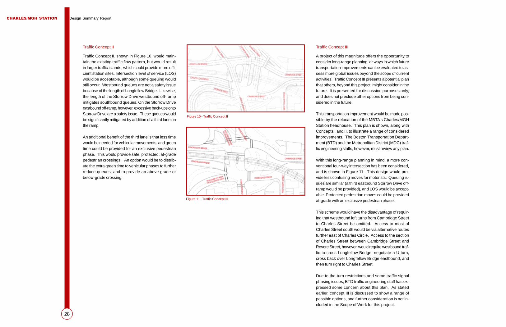
Traffic Concept II
Traffic Concept II, shown in Figure 10, would main-tain the existing traffic flow pattern, but would resultin larger traffic islands, which could provide more effi-cient station sites. Intersection level of service (LOS)would be acceptable, although some queuing wouldstill occur. Westbound queues are not a safety issuebecause of the length of Longfellow Bridge. Likewise,the length of the Storrow Drive westbound off-rampmitigates southbound queues. On the Storrow Driveeastbound off-ramp, however, excessive back-ups ontoStorrow Drive are a safety issue. These queues wouldbe significantly mitigated by addition of a third lane onthe ramp.
An additional benefit of the third lane is that less timewould be needed for vehicular movements, and greentime could be provided for an exclusive pedestrianphase. This would provide safe, protected, at-gradepedestrian crossings. An option would be to distrib-ute the extra green time to vehicular phases to furtherreduce queues, and to provide an above-grade orbelow-grade crossing.
Traffic Concept III
A project of this magnitude offers the opportunity toconsider long-range planning, or ways in which futuretransportation improvements can be evaluated to as-sess more global issues beyond the scope of currentactivities. Traffic Concept III presents a potential planthat others, beyond this project, might consider in thefuture. It is presented for discussion purposes only,and does not preclude other options from being con-sidered in the future.
This transportation improvement would be made pos-sible by the relocation of the MBTA’s Charles/MGHStation headhouse. This plan is shown, along withConcepts I and II, to illustrate a range of consideredimprovements. The Boston Transportation Depart-ment (BTD) and the Metropolitan District (MDC) traf-fic engineering staffs, however, must review any plan.
With this long-range planning in mind, a more con-ventional four-way intersection has been considered,and is shown in Figure 11. This design would pro-vide less confusing moves for motorists. Queuing is-sues are similar (a third eastbound Storrow Drive off-ramp would be provided), and LOS would be accept-able. Protected pedestrian moves could be providedat-grade with an exclusive pedestrian phase.
This scheme would have the disadvantage of requir-ing that westbound left turns from Cambridge Streetto Charles Street be omitted. Access to most ofCharles Street south would be via alternative routesfurther east of Charles Circle. Access to the sectionof Charles Street between Cambridge Street andRevere Street, however, would require westbound traf-fic to cross Longfellow Bridge, negotiate a U-turn,cross back over Longfellow Bridge eastbound, andthen turn right to Charles Street.
Due to the turn restrictions and some traffic signalphasing issues, BTD traffic engineering staff has ex-pressed some concern about this plan. As statedearlier, concept III is discussed to show a range ofpossible options, and further consideration is not in-cluded in the Scope of Work for this project.
Figure 10 - Traffic Concept II
Figure 11 - Traffic Concept III

CHARLES/MGH STATION Design Summary Report
29
The method for developing project options/potentialalternatives evolved from a process, which began byaccepting the constraints of the existing station loca-tion:
� The station is sited between the LongfellowBridge/Charles River and the Beacon Hill portal
� The platforms are elevated above-grade
� The track viaduct curvature precludes relocationof the platforms
Consideration was given to modify the station loca-tion by adding program elements, such as pedestrian/vehicular improvements, to meet the project goal ofaccess to Charles/MGH Station. Primary functionalcriteria were site and station access, program fit, traf-fic, and urban design fit.
Some solutions were ruled out without a graphic test.Station locations to the west of the existing stationand center platform options were dismissed for thefollowing reasons:
� Options to the west placed the station well pastreasonable access desire lines and conflicted withtraffic patterns on the Longfellow Bridge
� Center platform options were studied and foundto require major adjustments to track geometryand structure, which resulted in overwhelmingconstructability and operational issues
More desirable would be station relocation to the east.This would result in a less isolated site, more directlylinked to pedestrian desire lines.
Schemes that live within the existing site were testedfirst. These are referenced as “A” schemes. As op-tions move to the east, “B” schemes are developed.Finally, the most easterly site option studied is referredto as “C” schemes. All options were studied with “atgrade,” “tunnel,” and “bridge” solutions. Access im-provements often begged the question of modifyingexisting conditions, specifically traffic patterns. Rela-tive cost factors were assigned to each option, con-sidering scope of work, constructability, and opera-tional factors.
Headhouse Elements
For each site location option, station elements havebeen briefly described. The description is not to de-fine the architecture, but rather to list the major pro-gram elements as shown in the option.
Element descriptions deal with the three major aspectsof the option - the headhouse structure, the accesselement (i.e. bridge, tunnel, etc.), and the pedestrian/traffic modifications required for achieving access tothe station and circulation through the intersection.
Project Factors
After establishing the major project priorities with theMBTA, related agencies, and the community, eachoption has been reviewed with a comb of basic projectgoals and functional determinants. Problems or im-provements over the existing conditions are describedrelative to the issue topic. The cost of the option isprojected indicating its cost ranking relative to theother studied options. Finally, a letter grade is as-signed to the option indicating overall project valuerelative to expenditures.
Station Location Methodology

CHARLES/MGH STATION Design Summary Report
30
Design Concept
Working with the limits of the existing headhouse foot-print, rehabilitation options were developed with thefollowing parameters:
� Improvements to station access and ADA com-pliance will be accommodated in the station de-sign as limited by structure and existing layouts
� Existing structural frame and floor level elevationswill be retained
� Stairways to platform will remain in their existinglocations
� Upgrades to finishes and services will be limitedto the repair and replacement of existing features
� Design choices for the replacement of exteriormaterials will be in keeping with and will incorpo-rate the major materials of the existing station
� Station options will explore at grade, tunnel, andbridge access strategies
Track Alignment Modifications
The rail should be replaced with new 115 RE con-tinuous welded rail, as part of MBTA routine mainte-nance program. Existing crossties will require spotreplacement and re-spacing.
Traffic Modifications / Relocations
The station location would not result in changes toexisting roadway patterns or operations. As such, nosignificant traffic improvements would be required.
Pedestrian Access
The ability of pedestrians to cross at grade offers sig-nificant benefits, primarily in flexibility relating to over-pass requirements and in pedestrian convenience.North of the circle, existing traffic signal phasing wouldallow for protected at-grade pedestrian crossings,both across Cambridge Street westbound and acrossthe adjacent three-lane segments to the east of thestation house. South of the circle, however, a pro-
Project Options / Potential Alternatives
Rehabilitation of
Existing Station
Refer to Headhouse OptionsA1.0 | A1.1A | A1.1B | A1.2
tected pedestrian crossing across Cambridge Streeteastbound is not currently possible. The signal phas-ing currently allows continuous flow from either theLongfellow Bridge or the two Storrow Drive off-ramps.Taking green time away from any of these moves wouldonly increase queues and delays that are already toolong.
A minimal treatment would be to provide an at-grade,unprotected crosswalk across Cambridge Street east-bound, between Charles and West Cedar Streets. Noprotection would be provided, since signal timing/phasing would not be modified, but “crosswalk ahead”warning signs could be installed to alert motorists ofpedestrian activity.
Vehicular Access
New traffic guide signs and pavement markings, toreduce motorist confusion and to better define travelways, would be provided.

CHARLES/MGH STATION Design Summary Report
31
Description of Headhouse Elements
1 Major rehab to existing station headhouse� Station stripped back to structural steel frame – existing floor elevations are retained� Pay plaza relocated to grade level� Two minimum-size elevators are provided for disabled access from grade to platform levels� Stairs provide access to platforms for able-bodied travelers� Severely deteriorated existing cast stone façade is completely removed and replaced with a new façade
system engineered to withstand structurally induced vibrations.
2 Restriped crosswalk with advance “pedestrian crossing” warning sign
3 Existing protected pedestrian crossing
Project Factors
A TrafficMaintains existing traffic pattern.
B Barrier-Free Access to the StationPedestrian access to headhouse located inside a rotary is very difficult – too much waiting time for signalsleading to jaywalking and accidents. However, at grade access eliminates some stair climbing, com-pared to the existing station arrangements. Sight lines around piers are poor.
C Barrier-Free Access within the StationAccess in station via minimum size elevators. No escalators possible within existing headhouse footprint.
D Urban DesignHeadhouse isolated from the adjacent pedestrian activity and land uses by a sea of roadways – not partof the neighborhood.
E Noise MitigationThe physical design of the station has no effect in controlling rail noise. Effective passive noise controlpanels could be added to the faces of the track structure girders from the portal to the station.
F Compatibility with the Future Blue Line ExtensionVertical connections down to a tunnel linking the Blue Line extension would have to be constructed.Limited station area allows for elevator and stair link only. Tunnel connections are complicated by utilityinterference within the intersection.
G TrackExisting track layout remains. Updates to power and signal are required to meet code and operationsstandards.
H PlatformExisting platform is retained. Upgrades to finishes and general repairs are required to extend serviceablelife and update appearance.
I ConstructabilityMajor demolition and construction within the framework of the existing structure will require complexphasing and temporary enclosures and circulation pathways during construction. Station uses will besurrounded by construction on a daily basis.
J Cost $ K Value D
A 1.0
Major Rehabilitation
to Station at
Existing Location
with At-Grade Access

CHARLES/MGH STATION Design Summary Report
32
Project Factors
A TrafficTraffic pattern and signaling remain unchanged.
B Barrier-Free Access to the StationTunnel pathway avoids issues of surface traffic, however, tunnels are long and unsupervised, thus a potential forcriminal activity that will discourage their use and use of the station. Due to utilities, tunnels are deep, say +/- 35’from street to floor level, requiring escalators, elevators, and adding to the climb to the above ground platforms.
C Barrier-Free Access within the StationAccess from street to platform could require three separate elevator rides:1. Street level to tunnel2. Tunnel level to pay level3. Pay level to platformRemote location of elevators increases chance of vandalism, putting them out of service. Able-bodied accesspath is burdened with additional stairs from tunnel to upper level.
D Urban DesignHeadhouse isolated from the adjacent pedestrian activity and land uses by tunnel access - not part of theneighborhood. Street headhouses add little to the neighborhood as isolated elements. Unsupervised, thesestructures can become troublesome collectors of criminal or antisocial activity.
E Noise MitigationThe physical design of the station has no effect in controlling rail noise. Effective passive noise control panelscould be added to the faces of the track structure girders from the portal to the station.
F Compatibility with the Future Blue Line ExtensionTunnel connections to the Charles/MGH station would be directly linked to the Blue Line extension tunnel.Knock out panels constructed within the tunnel walls would facilitate phased connections between the twoprojects.
G TrackExisting track layout remains. Updates to power and signal are required to meet code and operations standards.
H PlatformExisting platform is retained. Upgrades to finishes and general repairs are required to extend serviceable life andupdate appearance.
I ConstructabilityMajor demolition and construction within the framework of the existing structure will require complex phasingand temporary enclosures and circulation pathways during construction. Major impact on existing utilities re-quires complex relocation and staging. Station uses will be surrounded by construction on a daily basis. Con-struction of pedestrian tunnels is difficult, costly, and impacts traffic during construction.
J Cost $$$ K Value D-
Description of Headhouse Elements
1 Major rehab to existing station headhouse� Station stripped back to structural steel frame – existing floor elevations are retained� Pay plaza relocated to grade level� Two minimum-size elevators are provided for disabled access from grade to platform levels� Stairs provide access to platforms for able-bodied travelers� Severely deteriorated existing cast stone façade is completely removed and replaced with a new façade
system engineered to withstand structurally induced vibrations.
2/3 Glass enclosed curbside headhouse with minimum elevator and stair elements.
4 Pedestrian tunnels with standard MBTA finishes. Tunnel locations below-grade governed by existing utili-ties. Water table near surface requires slurry wall type construction.
A 1.1A
Major Rehabilitation
to Station at
Existing Location
with Pedestrian
Tunnel Access
(Option A)

CHARLES/MGH STATION Design Summary Report
33
Project Factors
A TrafficTraffic pattern and signaling remain unchanged.
B Barrier-Free Access to the StationTunnel pathway avoids issues of surface traffic, however, tunnels are long and unsupervised, thus a potential forcriminal activity that will discourage their use and use of the station. Due to utilities, tunnels are deep, say +/-35’ from street to floor level, requiring escalators, elevators, and adding to the climb to the above groundplatforms.
C Barrier-Free Access within the StationAccess from street to platform could require three separate elevator rides:1. Street level to tunnel2. Tunnel level to pay level3. Pay level to platformRemote location of elevators increases chance of vandalism, putting them out of service. Able-bodied accesspath is burdened with additional stairs from tunnel to upper level
D Urban DesignHeadhouse isolated from the adjacent pedestrian activity and land uses by tunnel access - not part of theneighborhood. Street headhouses add little to the neighborhood as isolated elements. Unsupervised, thesestructures can become troublesome collectors of criminal or antisocial activity.
E Noise MitigationThe physical design of the station has no effect in controlling rail noise. Effective passive noise control panelscould be added to the faces of the track structure girders from the portal to the station.
F Compatibility with the Future Blue Line ExtensionTunnel connections to the Charles/MGH station would be directly linked to the Blue Line extension tunnel.Knock out panels constructed within the tunnel walls would facilitate phased connections between the twoprojects.
G TrackExisting track layout remains. Updates to power and signal are required to meet code and operations stan-dards.
H PlatformExisting platform is retained. Upgrades to finishes and general repairs are required to extend serviceable lifeand update appearance.
I ConstructabilityMajor demolition and construction within the framework of the existing structure will require complex phasingand temporary enclosures and circulation pathways during construction. Major impact on existing utilities re-quires complex relocation and staging. Station uses will be surrounded by construction on a daily basis.Construction of pedestrian tunnels is difficult, costly, and impacts traffic during construction.
J Cost $$$ K Value D-
Description of Headhouse Elements
1 Major rehab to existing station headhouse� Station stripped back to structural steel frame – existing floor elevations are retained� Pay plaza relocated to grade level� Two minimum-size elevators are provided for disabled access from grade to platform levels� Stairs provide access to platforms for able-bodied travelers� Severely deteriorated existing cast stone façade is completely removed and replaced with a new façade
system engineered to withstand structurally induced vibrations.
2/3 Glass enclosed curbside headhouse with minimum elevator and stair elements.
4 Pedestrian tunnels with standard MBTA finishes. Tunnel locations below-grade governed by existing utili-ties. Water table near surface requires slurry wall type construction.
5 Curb line is revised for new headhouse site.
A 1.1B
Major Rehabilitation
to Station at
Existing Location
with Pedestrian
Tunnel Access
(Option B)
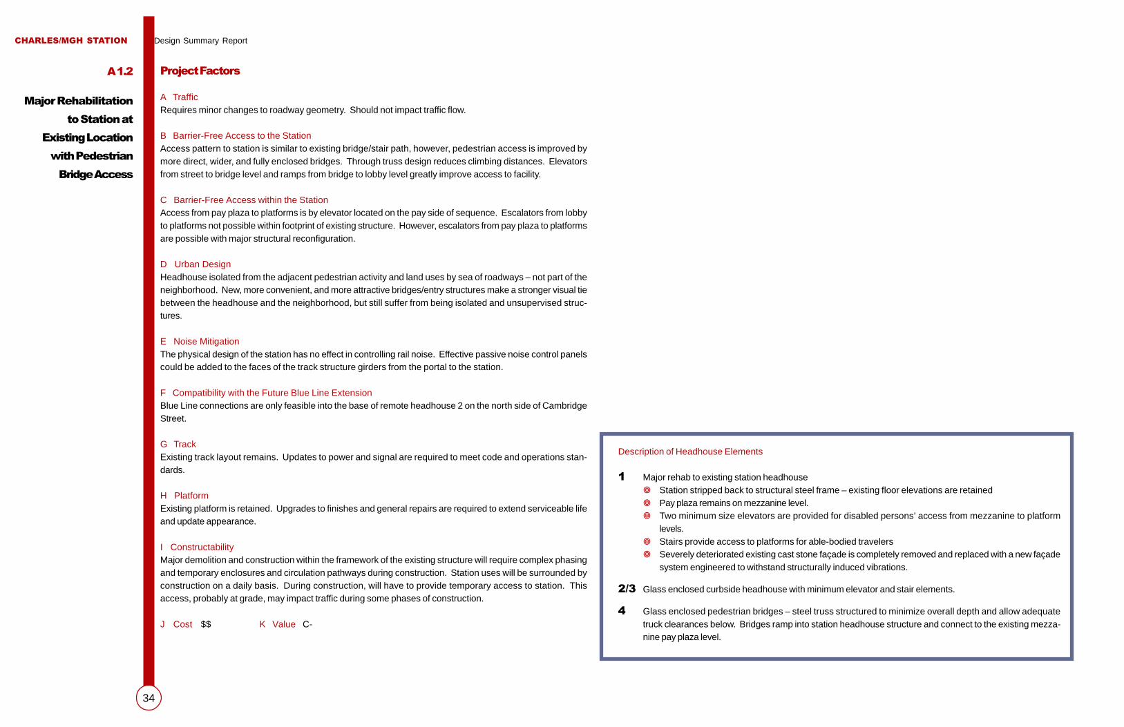
CHARLES/MGH STATION Design Summary Report
34
Description of Headhouse Elements
1 Major rehab to existing station headhouse� Station stripped back to structural steel frame – existing floor elevations are retained� Pay plaza remains on mezzanine level.� Two minimum size elevators are provided for disabled persons’ access from mezzanine to platform
levels.� Stairs provide access to platforms for able-bodied travelers� Severely deteriorated existing cast stone façade is completely removed and replaced with a new façade
system engineered to withstand structurally induced vibrations.
2/3 Glass enclosed curbside headhouse with minimum elevator and stair elements.
4 Glass enclosed pedestrian bridges – steel truss structured to minimize overall depth and allow adequatetruck clearances below. Bridges ramp into station headhouse structure and connect to the existing mezza-nine pay plaza level.
Project Factors
A TrafficRequires minor changes to roadway geometry. Should not impact traffic flow.
B Barrier-Free Access to the StationAccess pattern to station is similar to existing bridge/stair path, however, pedestrian access is improved bymore direct, wider, and fully enclosed bridges. Through truss design reduces climbing distances. Elevatorsfrom street to bridge level and ramps from bridge to lobby level greatly improve access to facility.
C Barrier-Free Access within the StationAccess from pay plaza to platforms is by elevator located on the pay side of sequence. Escalators from lobbyto platforms not possible within footprint of existing structure. However, escalators from pay plaza to platformsare possible with major structural reconfiguration.
D Urban DesignHeadhouse isolated from the adjacent pedestrian activity and land uses by sea of roadways – not part of theneighborhood. New, more convenient, and more attractive bridges/entry structures make a stronger visual tiebetween the headhouse and the neighborhood, but still suffer from being isolated and unsupervised struc-tures.
E Noise MitigationThe physical design of the station has no effect in controlling rail noise. Effective passive noise control panelscould be added to the faces of the track structure girders from the portal to the station.
F Compatibility with the Future Blue Line ExtensionBlue Line connections are only feasible into the base of remote headhouse 2 on the north side of CambridgeStreet.
G TrackExisting track layout remains. Updates to power and signal are required to meet code and operations stan-dards.
H PlatformExisting platform is retained. Upgrades to finishes and general repairs are required to extend serviceable lifeand update appearance.
I ConstructabilityMajor demolition and construction within the framework of the existing structure will require complex phasingand temporary enclosures and circulation pathways during construction. Station uses will be surrounded byconstruction on a daily basis. During construction, will have to provide temporary access to station. Thisaccess, probably at grade, may impact traffic during some phases of construction.
J Cost $$ K Value C-
A 1.2
Major Rehabilitation
to Station at
Existing Location
with Pedestrian
Bridge Access

CHARLES/MGH STATION Design Summary Report
35
Major Rehabilitation to
New Headhouse at
Existing Location
Refer to Headhouse OptionsA2.0 | A2.1A | A2.1B | A2.2
Design Concept
Working within the general limits of the existingheadhouse traffic island, new headhouse options weredeveloped with the following parameters:
� Station program areas are increased to allow ex-panded free and paid plaza areas, enlarged stairs,escalators, and elevator connections to the plat-forms
� Existing floor elevations will be retained
� New headhouse structure will replace existingframing
� Improvements to station access and ADA com-pliance will be maximized and will be featured inthe basic station design
� Exterior material choices will be in keeping withthe existing platform enclosures but will allowgreater visual transparency of the headhouse tobe developed
� Upgrades to finishes and services will update thestation to current MBTA standards
� Station options will explore at grade, tunnel, andbridge access strategies
Track Alignment Modifications
The rail should be replaced with new 115 RE con-tinuous welded rail, as part of MBTA routine mainte-nance program. Existing crossties will require spotreplacement and re-spacing.
Traffic Modifications / Relocations
The station location would not result in changes toexisting roadway patterns or operations. No signifi-cant traffic improvements would be required.
Pedestrian Access
The ability of pedestrians to cross at grade offers sig-nificant benefits, primarily in flexibility relating to over-pass requirements and in pedestrian convenience.North of the circle, existing traffic signal phasing wouldallow for protected at-grade pedestrian crossings,both across Cambridge Street westbound and acrossthe adjacent three-lane segments to the east of thestation house. South of the circle, however, a pro-tected pedestrian crossing across Cambridge Streeteastbound is not currently possible. The signal phas-ing currently allows continuous flow from either theLongfellow Bridge or the two Storrow Drive off-ramps.Taking green time away from any of these moves wouldonly increase queues and delays that are already toolong.
A minimal treatment would be to provide an at-grade,unprotected crosswalk across Cambridge Street east-bound, between Charles and West Cedar Streets. Noprotection would be provided, since signal timing/phasing would not be modified, but “crosswalk ahead”warning signs could be installed to alert motorists ofpedestrian activity.
Vehicular Access
New traffic guide signs and pavement markings toreduce motorist confusion and to better define travelways, would be provided.
Utilities
Constructing any new structures for this project willrequire significant relocation of existing utilities. Anyrelocation of electrical, water, gas and sewer may beperformed in a traditional manner. Since many of theexisting utilities are located in or near the streets, anyutility work will adversely affect traffic flow in the area.
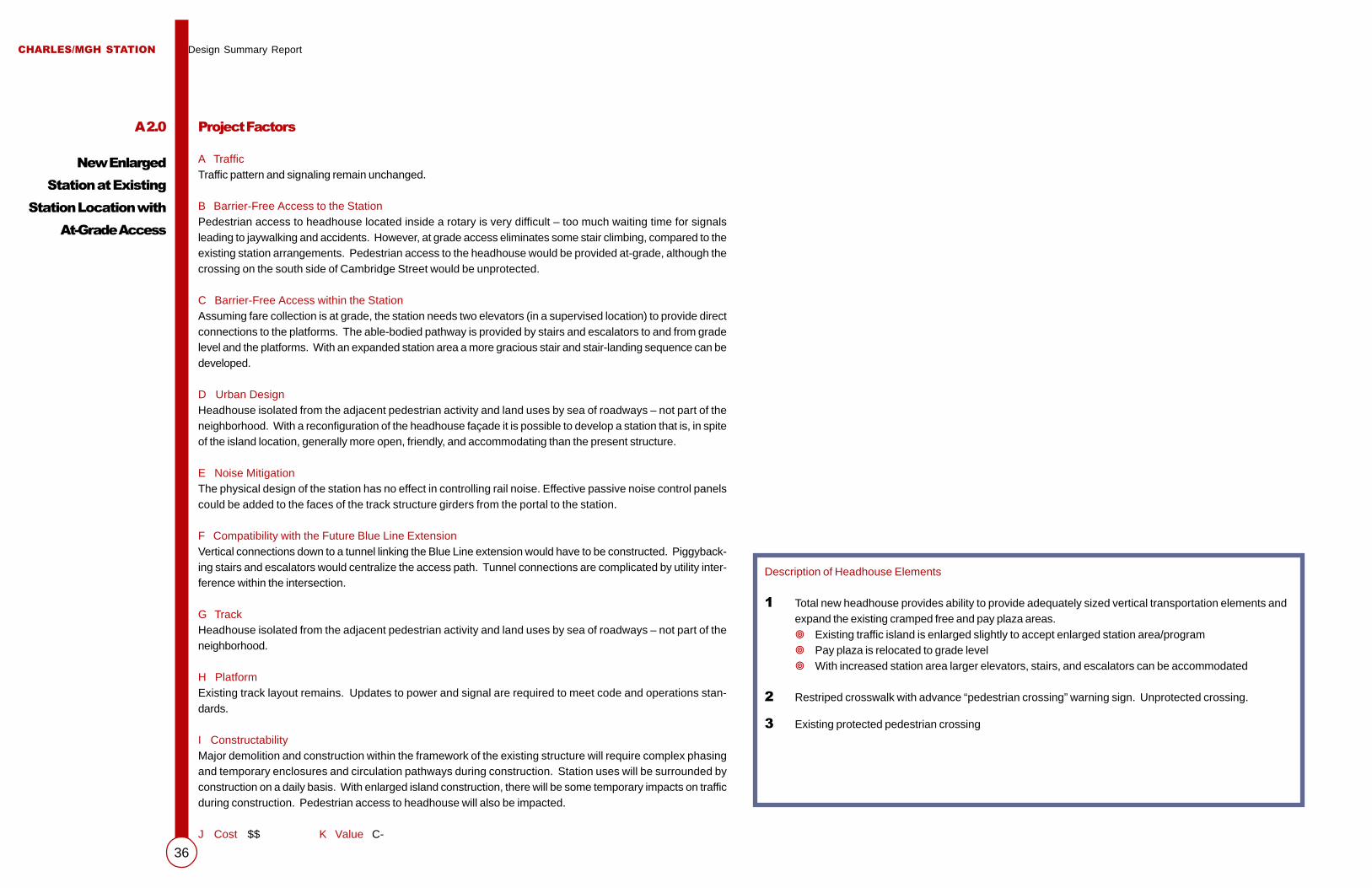
CHARLES/MGH STATION Design Summary Report
36
A 2.0
New Enlarged
Station at Existing
Station Location with
At-Grade Access
Description of Headhouse Elements
1 Total new headhouse provides ability to provide adequately sized vertical transportation elements andexpand the existing cramped free and pay plaza areas.� Existing traffic island is enlarged slightly to accept enlarged station area/program� Pay plaza is relocated to grade level� With increased station area larger elevators, stairs, and escalators can be accommodated
2 Restriped crosswalk with advance “pedestrian crossing” warning sign. Unprotected crossing.
3 Existing protected pedestrian crossing
Project Factors
A TrafficTraffic pattern and signaling remain unchanged.
B Barrier-Free Access to the StationPedestrian access to headhouse located inside a rotary is very difficult – too much waiting time for signalsleading to jaywalking and accidents. However, at grade access eliminates some stair climbing, compared to theexisting station arrangements. Pedestrian access to the headhouse would be provided at-grade, although thecrossing on the south side of Cambridge Street would be unprotected.
C Barrier-Free Access within the StationAssuming fare collection is at grade, the station needs two elevators (in a supervised location) to provide directconnections to the platforms. The able-bodied pathway is provided by stairs and escalators to and from gradelevel and the platforms. With an expanded station area a more gracious stair and stair-landing sequence can bedeveloped.
D Urban DesignHeadhouse isolated from the adjacent pedestrian activity and land uses by sea of roadways – not part of theneighborhood. With a reconfiguration of the headhouse façade it is possible to develop a station that is, in spiteof the island location, generally more open, friendly, and accommodating than the present structure.
E Noise MitigationThe physical design of the station has no effect in controlling rail noise. Effective passive noise control panelscould be added to the faces of the track structure girders from the portal to the station.
F Compatibility with the Future Blue Line ExtensionVertical connections down to a tunnel linking the Blue Line extension would have to be constructed. Piggyback-ing stairs and escalators would centralize the access path. Tunnel connections are complicated by utility inter-ference within the intersection.
G TrackHeadhouse isolated from the adjacent pedestrian activity and land uses by sea of roadways – not part of theneighborhood.
H PlatformExisting track layout remains. Updates to power and signal are required to meet code and operations stan-dards.
I ConstructabilityMajor demolition and construction within the framework of the existing structure will require complex phasingand temporary enclosures and circulation pathways during construction. Station uses will be surrounded byconstruction on a daily basis. With enlarged island construction, there will be some temporary impacts on trafficduring construction. Pedestrian access to headhouse will also be impacted.
J Cost $$ K Value C-

CHARLES/MGH STATION Design Summary Report
37
Description of Headhouse Elements
1 Total new headhouse provides ability to provide adequately sized vertical transportation elements andexpand the existing cramped free and pay plaza areas.� Existing traffic island is enlarged slightly to accept enlarged station area/program.� Pay plaza is located at tunnel level.� With increased station area larger elevators, stairs, and escalators can be accommodated.
2/3 Glass enclosed curbside headhouse with minimum elevator, stair, and escalator (up only) elements.
4 Pedestrian tunnels with standard MBTA finishes. Tunnel locations below grade governed by existingutilities. Water table near surface requires slurry wall type construction. Pay plaza is entered at tunnellevel. Fare collection activities at tunnel level allows a greater level of supervision and security to bepresent within the tunnel limits.
Project Factors
A TrafficTraffic pattern and signaling remain unchanged.
B Barrier-Free Access to the StationTunnel pathway avoids issues of surface traffic, however, tunnels are long and unsupervised, thus a poten-tial for criminal activity that will discourage their use and use of the station. Due to utilities, tunnels aredeep, say +/- 35’ from street to floor level, requiring escalators, elevators, and adding to the climb to theabove ground platforms.
C Barrier-Free Access within the StationAccess from street level to platform requires two elevator or escalator rides – street to tunnel, then tunnelto platform.
D Urban DesignHeadhouse isolated from the adjacent pedestrian activity and land uses by tunnel access – not part of theneighborhood. Street headhouses add little to the neighborhood as isolated elements. Unsupervised,these structures can become troublesome collectors of criminal or antisocial activity.
E Noise MitigationThe physical design of the station has no effect in controlling rail noise. Effective passive noise controlpanels could be added to the faces of the track structure girders from the portal to the station.
F Compatibility with the Future Blue Line ExtensionTunnel connections to the Charles/MGH station would be directly linked to the Blue Line extension tunnel.Knock-out panels constructed within the tunnel walls would facilitate phased connections between thetwo projects.
G TrackExisting track layout remains. Updates to power and signal are required to meet code and operationsstandards.
H PlatformExisting platform is retained. Upgrades to finishes and general repairs are required to extend serviceablelife and update appearance.
I ConstructabilityMajor demolition and construction within the framework of the existing structure will require complexphasing and temporary enclosures and circulation pathways during construction. Major impact on existingutilities requires complex relocation and staging. Station uses will be surrounded by construction on adaily basis. Construction of pedestrian tunnels is difficult, costly, and impacts traffic during construction.
J Cost $$$ K Value C-
A 2.1A
New Enlarged
Station at Existing
Station Location with
Pedestrian Tunnel
Access (Option A)

CHARLES/MGH STATION Design Summary Report
38
A 2.1B
New Enlarged
Station at Existing
Station Location with
Pedestrian Tunnel
Access (Option B)
Description of Headhouse Elements
1 Total new headhouse provides ability to provide adequately sized vertical transportation elements andexpand the existing cramped free and pay plaza areas.� Existing traffic island is enlarged slightly to accept enlarged station area/program� Pay plaza is located at tunnel level.� With increased station area larger elevators, stairs, and escalators (in both directions) can be ac-
commodated.
2/3 Glass-enclosed curbside headhouse with minimum elevator, stair, and escalator (up only) elements.
4 Pedestrian tunnels with standard MBTA finishes. Tunnel locations below grade governed by existingutilities. Water table near surface requires slurry wall type construction. Pay plaza is entered at tunnellevel. Fare collection activities at tunnel level allows a greater level of supervision and security to bepresent within the tunnel limits.
5 Curb line is revised for new headhouse site.
Project Factors
A TrafficTraffic pattern and signaling remain unchanged.
B Barrier-Free Access to the StationTunnel pathway avoids issues of surface traffic, however, tunnels are long and unsupervised, thus a potential forcriminal activity that will discourage their use and use of the station. Due to utilities, tunnels are deep, say +/-35’ from street to floor level, requiring escalators, elevators, and adding to the climb to the above groundplatforms.
C Barrier-Free Access within the StationAccess from street level to platform requires two elevator or escalator rides – street to tunnel, then tunnel toplatform.
D Urban DesignHeadhouse isolated from the adjacent pedestrian activity and land uses by tunnel access – not part of theneighborhood. Street headhouses add little to the neighborhood as isolated elements. Unsupervised, thesestructures can become troublesome collectors of criminal or antisocial activity.
E Noise MitigationThe physical design of the station has no effect in controlling rail noise. Effective passive noise control panelscould be added to the faces of the track structure girders from the portal to the station.
F Compatibility with the Future Blue Line ExtensionTunnel connections to the Charles/MGH station would be directly linked to the Blue Line extension tunnel.Knock-out panels constructed within the tunnel walls would facilitate phased connections between the twoprojects.
G TrackExisting track layout remains. Updates to power and signal are required to meet code and operations stan-dards.
H PlatformExisting platform is retained. Upgrades to finishes and general repairs are required to extend serviceable lifeand update appearance.
I ConstructabilityMajor demolition and construction within the framework of the existing structure will require complex phasingand temporary enclosures and circulation pathways during construction. Major impact on existing utilities re-quires complex relocation and staging. Station uses will be surrounded by construction on a daily basis. Con-struction of pedestrian tunnels is difficult, costly, and impacts traffic during construction.
J Cost $$$ K Value C-

CHARLES/MGH STATION Design Summary Report
39
Description of Headhouse Elements
1 Total new headhouse provides ability to provide adequately-sized vertical transportation elements andexpand the existing cramped free and pay plaza areas.� Existing traffic island is enlarged slightly to accept enlarged station area/program� Pay plaza remains at mezzanine level� With increased station area larger, elevators, stairs, and escalators can be accommodated
2/3 Glass-enclosed curbside headhouses with minimum elevator and stair elements.
4 Glass-enclosed pedestrian bridges – steel truss structured to minimize overall depth and allow adequatetruck clearance of 14’-6” below. Bridges ramp into station headhouse structure and connect to theexisting mezzanine pay plaza level.
Project Factors
A TrafficRequires minor changes to roadway geometry. Should not impact traffic flow.
B Barrier-Free Access to the StationAccess pattern to station is similar to existing bridge/stair path, however, pedestrian access is improvedby more direct, wider, and fully enclosed bridges. Through truss design reduces climbing distances.Elevators from street to bridge level and ramps from bridge to lobby level greatly improve access to facility.
C Barrier-Free Access within the StationAssuming fare collection is at the mezzanine level, two elevators (in a supervised location) provide directconnections to the platforms. The able-bodied pathway is provided by stairs and escalators (up only) toand from the mezzanine level and the platforms. With an expanded station area, a more gracious stair andstair landing can be developed.
D Urban DesignHeadhouse isolated from the adjacent pedestrian activity and land uses by ramp access – not part of theneighborhood. With a reconfiguration of the headhouse façade it is possible to develop a station that is,in spite of the island location, generally more open, friendly, and accommodating than the present struc-ture. With a new headhouse structure it is easier to integrate the bridges with the headhouse. This makesthe headhouse visually and physically more a part of the neighborhood.
E Noise MitigationThe physical design of the station has no effect in controlling rail noise. Effective passive noise controlpanels could be added to the faces of the track structure girders from the portal to the station.
F Compatibility with the Future Blue Line ExtensionBlue Line connections are only feasible into the base of remote headhouse 2 on the north side of Cam-bridge Street.
G TrackExisting track layout remains. Updates to power and signal are required to meet code and operationsstandards.
H PlatformExisting platform is retained. Upgrades to finishes and general repairs are required to extend serviceablelife and update appearance.
I ConstructabilityMajor demolition and construction within the framework of the existing structure will require complexphasing and temporary enclosures and circulation pathways during construction. Station uses will besurrounded by construction on a daily basis. With enlarged island construction, there will be some tempo-rary impacts on traffic during construction. Pedestrian access to headhouse will also be impacted.
J Cost $$ K Value C+
A 2.2
New Enlarged
Station at Existing
Station Location with
Bridge Access

CHARLES/MGH STATION Design Summary Report
39
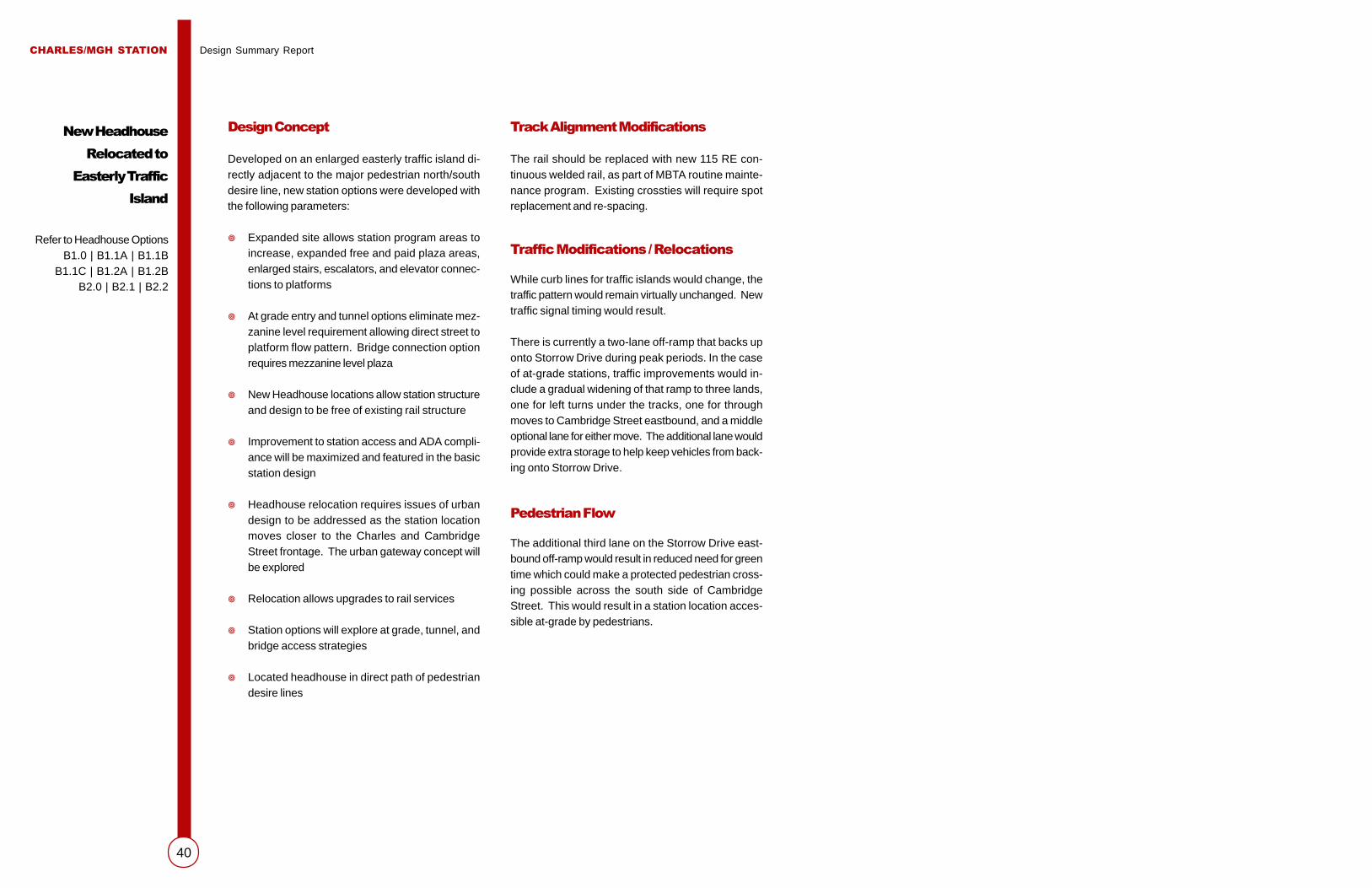
CHARLES/MGH STATION Design Summary Report
40
Design Concept
Developed on an enlarged easterly traffic island di-rectly adjacent to the major pedestrian north/southdesire line, new station options were developed withthe following parameters:
� Expanded site allows station program areas toincrease, expanded free and paid plaza areas,enlarged stairs, escalators, and elevator connec-tions to platforms
� At grade entry and tunnel options eliminate mez-zanine level requirement allowing direct street toplatform flow pattern. Bridge connection optionrequires mezzanine level plaza
� New Headhouse locations allow station structureand design to be free of existing rail structure
� Improvement to station access and ADA compli-ance will be maximized and featured in the basicstation design
� Headhouse relocation requires issues of urbandesign to be addressed as the station locationmoves closer to the Charles and CambridgeStreet frontage. The urban gateway concept willbe explored
� Relocation allows upgrades to rail services
� Station options will explore at grade, tunnel, andbridge access strategies
� Located headhouse in direct path of pedestriandesire lines
Track Alignment Modifications
The rail should be replaced with new 115 RE con-tinuous welded rail, as part of MBTA routine mainte-nance program. Existing crossties will require spotreplacement and re-spacing.
Traffic Modifications / Relocations
While curb lines for traffic islands would change, thetraffic pattern would remain virtually unchanged. Newtraffic signal timing would result.
There is currently a two-lane off-ramp that backs uponto Storrow Drive during peak periods. In the caseof at-grade stations, traffic improvements would in-clude a gradual widening of that ramp to three lands,one for left turns under the tracks, one for throughmoves to Cambridge Street eastbound, and a middleoptional lane for either move. The additional lane wouldprovide extra storage to help keep vehicles from back-ing onto Storrow Drive.
Pedestrian Flow
The additional third lane on the Storrow Drive east-bound off-ramp would result in reduced need for greentime which could make a protected pedestrian cross-ing possible across the south side of CambridgeStreet. This would result in a station location acces-sible at-grade by pedestrians.
New Headhouse
Relocated to
Easterly Traffic
Island
Refer to Headhouse OptionsB1.0 | B1.1A | B1.1B
B1.1C | B1.2A | B1.2BB2.0 | B2.1 | B2.2

CHARLES/MGH STATION Design Summary Report
41
B 1.0
New Station at
Cambridge Street
Island with
At-Grade Access
Project Factors
A TrafficTraffic patterns would be similar to existing conditions and signal timing would be modified.
B Barrier-Free Access to the StationPedestrian access to station requires an expanded sidewalk/curb line with pedestrian crosswalk signals toallow safe crossing of eastbound Cambridge Street. Access to the station would be provided at-grade witha protected phase.
C Barrier-Free Access within the StationAssuming fare collection is at grade, the station needs two elevators to provide direct connections to theplatforms. The able-bodied pathway is by stairs and escalators. Due to space limits of the site, escalatorsare only in the up direction. Short ramps connect the top landing of the stair/escalator/elevator complex tothe existing platforms west of the proposed station.
D Urban DesignThis scheme provides a major improvement to the urban design aspects of the station. The headhouse is nolonger visually and physically isolated from the neighborhood. As an object located at the edge of theintersection, the form of the station can become a strong visual conclusion to the river/bridge/city sequence.
E Noise MitigationBy enclosing more of the track along the curve with station and covered platform access, the physical formof the station begins to control rail noise. Rail noise from the portal to the station could be controlled withpassive noise panels added to the faces of the track structure girders. A complete enclosure of this areawould be studied with the design of the headhouse structure for optimal benefit.
F Compatibility with the Future Blue Line ExtensionVertical connections down to a tunnel linking the Blue Line extension would have to be constructed. Piggy-backing stairs and escalators would centralize the access path. Tunnel connections are complicated byutility interference within the intersection.
G TrackExisting track layout remains. Updates to power and signal are required to meet code and operationsstandards.
H PlatformThe station location provides an opportunity to enlarge the easterly ends of the platforms to allow improvedcrowd egress during special events.
I ConstructabilityConstructability is enhanced over “A” station schemes, as existing station headhouse and bridges can bekept in full operation during the construction period. As a result, this will reduce costs.
J Cost $$ K Value B
Description of Headhouse Elements
1 Totally new headhouse, located on pedestrian desire lines, provide the opportunity to locate the stationcloser to natural crossing points. Fare plaza is located at grade with elevator, stair, and escalator accessto platforms.
2 At-grade pedestrian crossings would be provided.
3 Curb line would be built out to reduce pedestrian crossing distance.
4 Storrow Drive eastbound off-ramp is widened to three lanes.

CHARLES/MGH STATION Design Summary Report
42
Description of Headhouse Elements
1 Totally new headhouse fills the easterly traffic island. This option assumes that existing traffic patternsremain unchanged. As such, curbside headhouses provide access to a pedestrian tunnel below gradewith fare collection at this level.
2/3 Glass enclosed curbside headhouse with minimum elevator and stair elements.
4 Pedestrian tunnels with standard MBTA finishes. Tunnel locations below grade governed by existingutilities. Water table near surface requires slurry wall type construction.
Project Factors
A TrafficTraffic pattern and signaling remain unchanged.
B Barrier-Free Access to the StationTunnel pathway avoids issues of surface traffic, however, tunnels are long and unsupervised, thus a potential forcriminal activity that will discourage their use and use of the station. Due to utilities, tunnels are deep, say +/- 35’ fromstreet to floor level, requiring escalators, elevators, and adding to the climb to the above ground platforms.
C Barrier-Free Access within the StationAccess from street level to platform requires two elevator rides – street to tunnel, then tunnel to platform.
D Urban DesignThis scheme provides a major improvement to the urban design aspects of the station. The headhouse is no longervisually and physically isolated from the neighborhood. As an object located at the edge of the intersection, the formof the station can become a strong visual conclusion to the river/bridge/city sequence. However, curbside headhousesadd little to the neighborhood as isolated elements. The possibility of blending the northerly headhouse into futureMGH development would greatly improve the neighborhood fit and improve security.
E Noise MitigationBy enclosing more of the track along the curve with station and covered platform access, the physical form of thestation begins to control rail noise. Rail noise from the portal to the station could be controlled with passive noisepanels added to the faces of the track structure girders. A complete enclosure of this area would be studied with thedesign of the headhouse structure for optimal benefit.
F Compatibility with the Future Blue Line ExtensionTunnel connections to the Charles/MGH station would be directly linked to the Blue Line extension tunnel. Knock outpanels constructed within the tunnel walls would facilitate phased connections between the two projects.
G TrackExisting track layout remains. Updates to power and signal are required to meet code and operations standards.
H PlatformExisting platform is retained. Upgrades to finishes and general repairs are required to extend serviceable life andupdate appearance.
I ConstructabilityConstructability is enhanced over “A” station schemes, as existing station headhouse and bridges can be kept in fulloperation during the construction period. As a result, this will reduce costs. Construction of pedestrian tunnels addsto the cost and complexity of this option. Major impacts to existing utilities require complex relocation and staging.While the station itself remains free of existing traffic, tunnel construction will involve phased construction and generaldisruptions to traffic flow in the intersection. Existing bridges to station should remain in service during tunnel con-struction activity.
J Cost $$$ K Value C
B 1.1A
New Station at
Cambridge Street
Island with
Tunnel Access
(Option A)

CHARLES/MGH STATION Design Summary Report
43
Description of Headhouse Elements
1 Totally new headhouse fills the easterly traffic island. This option assumes that existing traffic patternsremain unchanged. As such, curbside headhouses provide access to a pedestrian tunnel below gradewith fare collection at this level.
2/3 Glass enclosed curbside headhouse with minimum elevator and stair elements. Expanded curb line forheadhouse site.
4 Pedestrian tunnels with standard MBTA finishes. Tunnel locations below grade governed by existingutilities. Water table near surface requires slurry wall-type construction.
Project Factors
A TrafficTraffic pattern and signaling remain unchanged.
B Barrier-Free Access to the StationTunnel pathway avoids issues of surface traffic, however, tunnels are long and unsupervised, thus a potential forcriminal activity that will discourage their use and use of the station. Due to utilities, tunnels are deep, say +/- 35’from street to floor level, requiring escalators, elevators, and adding to the climb to the above ground platforms.
C Barrier-Free Access within the StationAccess from street level to platform requires two elevator or escalator rides – street to tunnel, then tunnel to plat-form.
D Urban DesignThis scheme provides a major improvement to the urban design aspects of the station. The headhouse is no longervisually and physically isolated from the neighborhood. As an object located at the edge of the intersection, the formof the station can become a strong visual conclusion to the river/bridge/city sequence. However, curbside headhousesadd little to the neighborhood as isolated elements. The possibility of blending the northerly headhouse into futureMGH development would greatly improve the neighborhood fit and improve security.
E Noise MitigationBy enclosing more of the track along the curve with station and covered platform access, the physical form of thestation begins to control rail noise. Rail noise from the portal to the station could be controlled with passive noisepanels added to the faces of the track structure girders. A complete enclosure of this area would be studied with thedesign of the headhouse structure for optimal benefit.
F Compatibility with the Future Blue Line ExtensionTunnel connections to the Charles/MGH station would be directly linked to the Blue Line extension tunnel. Knock-out panels constructed within the tunnel walls would facilitate phased connections between the two projects.
G TrackExisting track layout remains. Updates to power and signal are required to meet code and operations standards.
H PlatformExisting platform is retained. Upgrades to finishes and general repairs are required to extend serviceable life andupdate appearance.
I ConstructabilityConstructability is enhanced over “A” station schemes, as existing station headhouse and bridges can be kept in fulloperation during the construction period. As a result, this will reduce costs. Construction of pedestrian tunnelsadds to the cost and complexity of this option. Major impacts to existing utilities require complex relocation andstaging. While the station itself remains free of existing traffic, tunnel construction will involve phased constructionand general disruptions to traffic flow in the intersection. Existing bridges to station should remain in service duringtunnel construction activity.
J Cost $$$ K Value C-
B 1.1B
New Station at
Cambridge Street
Island with
Tunnel Access
(Option B)

CHARLES/MGH STATION Design Summary Report
44
Description of Headhouse Elements
1 Totally new headhouse fills the easterly traffic island. This option assumes that existingtraffic patterns remain unchanged. As such, curbside headhouses provide access to apedestrian tunnel below grade with fare collection at this level.
2 Glass enclosed curbside headhouse with minimum elevator and stair elements.
3 Headhouse 3 replaces the CVS store and becomes part of the streetscape edge.
4 Pedestrian tunnels with standard MBTA finishes. Tunnel locations below grade governedby existing utilities. Water table near surface requires slurry wall type construction.
5 CVS site is completed with a new retail space adjacent to the headhouse 3 entry. Thedesign of elements 3 and 5 combine to produce a compatible architecture within the His-toric District.
Project Factors
A TrafficTraffic pattern and signaling remain unchanged.
B Barrier-Free Access to the StationTunnel pathway avoids issues of surface traffic, however, tunnels are long and unsupervised, thus a potential for criminal activitythat will discourage their use and use of the station. Due to utilities, tunnels are deep, say +/- 35’ from street to floor level, requiringescalators, elevators, and adding to the climb to the above ground platforms.
C Barrier-Free Access within the StationAccess from street level to platform requires two elevator rides – street to tunnel, then tunnel to platform.
D Urban DesignThis scheme provides a major improvement to the urban design aspects of the station. The headhouse is no longer visually andphysically isolated from the neighborhood. As an object located at the edge of the intersection, the form of the station can becomea strong visual conclusion to the river/bridge/city sequence. Headhouse elements blend into proposed future MGH developmentand extend the historic fabric at Charles Street.
E Noise MitigationBy enclosing more of the track along the curve with station and covered platform access, the physical form of the station begins tocontrol rail noise. Rail noise from the portal to the station could be controlled with passive noise panels added to the faces of thetrack structure girders. A complete enclosure of this area would be studied with the design of the Head House structure foroptimal benefit.
F Compatibility with the Future Blue Line ExtensionTunnel connections to the Charles/MGH station would be directly linked to the Blue Line extension tunnel. Knock out panelsconstructed within the tunnel walls would facilitate phased connections between the two projects.
G TrackExisting track layout remains. Updates to power and signal are required to meet code and operations standards.
H PlatformExisting platform is retained. Upgrades to finishes and general repairs are required to extend serviceable life and update appear-ance.
I ConstructabilityConstructability is enhanced over “A” station schemes, as existing station Head House and bridges can be kept in full operationduring the construction period. As a result, this will reduce costs. Construction of pedestrian tunnels adds to the cost andcomplexity of this option. Major impacts to existing utilities require complex relocation and staging. While the station itself remainsfree of existing traffic, tunnel construction will involve phased construction and general disruptions to traffic flow in the intersection.Existing bridges to station should remain in service during tunnel construction activity. Land taking of CVS site increases cost ofthis option.
J Cost $$$$ K Value C
B 1.1C
New Station at
Cambridge Street
Island with
Tunnel Access
(Option C)

CHARLES/MGH STATION Design Summary Report
45
Description of Headhouse Elements
1 Pay lobby and free passage circulation are on levels above the train. The stationbecomes one story taller than the existing station. The station, in effect, spans overthe train.
2/3/5 Headhouse elements are three-story structures matching the existing street massingor blending into future development at MGH. Headhouse 3 replaces the CVS store.
4 Pedestrian bridges – steel truss structures span the street well above the traffic andabove local sight planes. In the architectural development of the bridge design onthis option, a gentle continuous curve could be developed to produce a large scaleentry wall to the city.
Project Factors
A TrafficTraffic pattern and signaling remain unchanged.
B Barrier-Free Access to the StationRemote headhouses provide escalator, stair, and elevator connections to the bridge structure above. With the pay plaza abovethe train, increasing vertical travel, it is necessary to provide escalators in both directions.
C Barrier-Free Access within the StationAccess is provided in the remote headouses by elevators to the bridge structure. Elevators down from the pay plaza to theplatforms complete the accessible pathway.
D Urban DesignAn over the track station becomes a visual gateway or a monster that looms above the street. Developed to full advantage, thestation has views of the river, becomes a gateway feature and marks the station in the landscape.
E Noise MitigationBy enclosing more of the track along the curve with station and covered platform access, the physical form of the station beginsto control rail noise. Rail noise from the portal to the station could be controlled with passive noise panels added to the faces ofthe track structure girders. A complete enclosure of this area would be studied with the design of the headhouse structure foroptimal benefit.
F Compatibility with the Future Blue Line ExtensionBlue Line connections are only feasible into the base of remote Headhouse 2 on the north side of Cambridge Street.
G TrackExisting track layout remains. Updates to power and signal are required to meet code and operations standards.
H PlatformEasterly ends of the platform could be widened to ease entry and exiting moves by travelers.
I ConstructabilityConstructability is enhanced over “A” station schemes, as existing station headhouse and bridges can be kept in full operationduring the construction period. As a result, this will reduce costs. Long span bridge elements will require weekend or off-hourplacement to reduce impacts to traffic. Land taking of CVS site increases cost of this option.
J Cost $$ K Value B-
B 1.2A
New Station at
Cambridge Street
Island with
Bridge Access
(Option A)

CHARLES/MGH STATION Design Summary Report
46
Description of Headhouse Elements
1 Pay lobby and free passage circulation are on levels above the train. The stationbecomes one story taller than the existing station. The station spans over the train.
2/3 Headhouse elements are three-story structures matching the existing street mass-ing or blending into future development facades at MGH.
4 Pedestrian bridges – steel truss structures span the street well above the trafficand above local sight planes. In the architectural development of the bridge de-sign on this option, a gentle continuous curve could be developed to produce alarge scale entry wall to the city.
Project Factors
A TrafficTraffic pattern and signaling remain unchanged.
B Barrier-Free Access to the StationRemote headhouses provide escalator, stair, and elevator connections to the bridge structure above. With the pay plaza above thetrain, increasing vertical travel, it is necessary to provide escalators in both directions.
C Barrier-Free Access within the StationAccess is provided in the remote headhouses by elevators to the bridge structure. Elevators down from the pay plaza to the platformscomplete the accessible pathway.
D Urban DesignAn over-the-track station becomes a visual gateway or a monster that looms above the street. Developed to full advantage, thestation has views of the river, becomes a gateway feature and marks the station in the landscape.
E Noise MitigationBy enclosing more of the track along the curve with station and covered platform access, the physical form of the station begins tocontrol rail noise. Rail noise from the portal to the station could be controlled with passive noise panels added to the faces of thetrack structure girders. A complete enclosure of this area would be studied with the design of the headhouse structure for optimalbenefit.
F Compatibility with the Future Blue Line ExtensionBlue Line connections are only feasible into the base of remote headhouse 2 on the north side of Cambridge Street.
G TrackExisting track layout remains. Updates to power and signal are required to meet code and operations standards.
H PlatformEasterly ends of the platform could be widened to ease entry and exiting moves by travelers.
I ConstructabilityConstructability is enhanced over the “A” station schemes, as existing station headhouse and bridges can be kept in full operationduring the construction period. As a result, this will reduce costs. Long span bridge elements will require weekend or off-hourplacement to reduce impacts to traffic.
J Cost $$ K Value B
B 1.2B
New Station at
Cambridge Street
Island with
Bridge Access
(Option B)

CHARLES/MGH STATION Design Summary Report
47
Description of Headhouse Elements
1/4 Station island configuration requires reconstruction of roadway system, though thetraffic flow pattern and capacity will be similar to the existing layout. The roadwaybetween the existing Red Line piers is eliminated and a new roadway will be lo-cated between piers to the west, the site of the existing headhouse. The islands willbe reconfigured to suit the shift of these roadways toward the west. The enlargedCambridge Street island extends from existing piers 4 to 6.
2/3 Curb line is modified to allow at-grade access to the station with pedestrian cross-ing signal.
5 Storrow Drive eastbound off-ramp is widened to three lanes
Project Factors
A TrafficAlthough traffic islands shift slightly to the west, traffic patterns remain virtually unchanged. Traffic signal phasing would include apedestrian phase.
B Barrier-Free Access to the StationPedestrian access to the station is direct, at-grade, with protected crossing of eastbound and westbound Cambridge Street. Path ofstation travel and desire lines are the same.
C Barrier-Free Access within the StationDisabled persons and all other pedestrian movements on the island and from lobby to platform are enhanced due to the additionalspace available on the enlarged island. There is room for up and down escalators, larger than minimum elevators, and wide stairs. Ashort ramp connects the landing at the top of the stair/escalator/elevator ensemble to the end of the platforms. There is generousspace for pedestrian circulation on the island inside and outside of the headhouse.
D Urban DesignThe headhouse is part of the neighborhood and offers the opportunity to be a significant urban design element forming a gateway fortravelers passing on foot and in vehicles in all directions through the site. Pedestrian amenities, like those provided in HarvardSquare, would be incorporated in the streetscape. As the design develops, it is important that the station retains an open, dynamicquality vs. a static, stopper-like image.
E Noise MitigationBy enclosing more of the track along the curve with station and covered platform access, the physical form of the station begins tocontrol rail noise. Rail noise from the portal to the station could be controlled with passive noise panels added to the faces of thetrack structure girders. A complete enclosure of this area would be studied with the design of the Head House structure for optimalbenefit.
F Compatibility with the Future Blue Line ExtensionVertical connections down to a tunnel linking the Blue Line extension would have to be constructed. Piggybacking stairs andescalators would centralize the access path. Tunnel connections are complicated by utility interference within the intersection.
G TrackModifications to track supports – piers would enhance and improve the flow through the station. One pier, located in the new station,would be replaced with columns to allow pedestrian circulation in the fare collection area.
H PlatformEasterly ends of the platform could be widened to ease entry and exiting moves by travelers.
I ConstructabilityAs this scheme eliminates the existing headhouse, various temporary measures are necessary to keep the station open for use andto maintain vehicular traffic. For example, four lanes can be filled in between existing piers, and two temporary U-turn lanes can becreated just east of the island. Thus, the existing headhouse would stay in service while the new one is being built. Careful reviewof existing utilities needs to be addressed in the design process to reduce or eliminate the need to relocate major utility lines andbranches.
J Cost $$+ K Value B+ to A
B 2.0
New Station at
Enlarged Cambridge
Street Island with
At-Grade Access

CHARLES/MGH STATION Design Summary Report
48
Description of Headhouse Elements
1/4 Station island configuration requires reconstruction of roadway system, though thetraffic flow pattern and capacity will be similar to the existing layout. The roadwaybetween existing Red Line piers is eliminated. A new roadway will be located be-tween existing piers to the west, the site of the existing headhouse. The islands willbe reconfigured to suit the shift of these roadways toward the west. The enlargedCambridge Street island extends from pier 4 to pier 6.
2 Glass enclosed curbside headhouse with minimum elevator and stair elements.
3 Pedestrian tunnels with standard MBTA finishes. Tunnel locations below grade gov-erned by existing utilities. Water table near surface requires slurry wall type con-struction.
5 Curb line relocated to allow for remote headhouse access to pedestrian tunnels.
Project Factors
A TrafficAlthough traffic islands shift slightly to the west, traffic patterns remain virtually unchanged.
B Barrier-Free Access to the StationPedestrian access to the station is direct in the horizontal plane, but requires a lot more up and down movement, common to all thetunnel alternatives. Fare collection lobby would be in tunnel. Due to utilities, tunnels are deep, say +/- 35’ from street to floor level,requiring escalators, elevators, and adding to the climb to the above ground platforms.
C Barrier-Free Access within the StationDisabled persons’ access is via elevator from street to tunnel – elevator from tunnel to platform assuming pay plaza is at tunnellevel.
D Urban DesignThe headhouse is part of the neighborhood and offers the opportunity to be a significant urban design element forming a gatewayfor travelers passing on foot and in vehicles in all directions through the site. As the design develops, it is important that the stationretains an open, dynamic quality vs. a static, stopper-like image. Street side headhouses add little to the neighborhood as isolatedelements. The possible blending of the northerly headhouse with future MGH development would improve this issue somewhat.
E Noise MitigationBy enclosing more of the track along the curve with station and covered platform access, the physical form of the station begins tocontrol rail noise. Rail noise from the portal to the station could be controlled with passive noise panels added to the faces of thetrack structure girders. A complete enclosure of this area would be studied with the design of the Head House structure foroptimal benefit.
F Compatibility with the Future Blue Line ExtensionTunnel connections to the Charles/MGH station would be directly linked to the Blue Line extension tunnel. Knock-out panelsconstructed within the tunnel walls would facilitate phased connections between the two projects.
G TrackExisting track layout remains. Updates to power and signal are required to meet code and operations standards.
H PlatformEasterly ends of the platform could be widened to ease entry and exiting moves by travelers.
I ConstructabilityAs this scheme eliminates the existing headhouse, various temporary measures are necessary to keep the station open for use andto maintain vehicular traffic. For example, four lanes can be filled in between existing piers, and two temporary U-turn lanes can becreated just east of the island. Thus, the existing headhouse would stay in service while the new one is being built. Major impactsto existing utilities require complex relocation and staging. Tunnel construction activity will have a major additional impact on trafficand the neighborhood.
J Cost $$$$ K Value B-
B 2.1
New Station at
Enlarged Cambridge
Street Island with
Tunnel Access

CHARLES/MGH STATION Design Summary Report
49
Description of Headhouse Elements
1 Assuming fare collection is at the mezzanine level, two elevators in a supervised loca-tion provide direct connections to the platforms. The able-bodied pathway is pro-vided by stairs and escalators (up only) to and from the mezzanine level and the plat-forms. With an expanded station area, a more gracious stair and stair landing can bedeveloped.
2 Glass enclosed curbside headhouse with minimum elevator and stair elements.
3 Glass enclosed pedestrian bridges – steel truss structured to minimize overall depthand allow adequate truck clearances below. Bridges ramp into station headhousestructure and connect to the mezzanine pay plaza level.
4/5 Station island configuration requires reconstruction of roadway system, though thetraffic flow pattern and capacity will be similar to the existing layout. The roadwaybetween existing Red Line piers is eliminated and a new roadway will be locatedbetween piers to the west, the site of the existing headhouse. The islands will bereconfigured to suit the shift of these roadways toward the west. The enlarged Cam-bridge Street island extends from pier 4 to pier 6.
Project Factors
A TrafficAlthough traffic islands shift slightly to the west, traffic patterns remain virtually unchanged.
B Barrier-Free Access to the StationAccess pattern to station is similar to existing bridge/stair path, however, pedestrian access is improved by more direct, wider,and fully enclosed bridges. Through truss design reduces climbing distances. Elevators from street to bridge level and rampsfrom bridge to lobby level greatly improve access to facility.
C Barrier-Free Access within the StationDisabled persons’ access follows the able-bodied path as described above, plus elevators and stairs at the street entry to thebridges. A short ramp connects the landing at the top of the stair/escalator/elevator ensemble from the lobby to the end of theplatforms, as in B2.0.
D Urban DesignThe headhouse is part of the neighborhood and offers the opportunity to be a significant urban design element forming a gatewayfor travelers passing on foot and in vehicles in all directions through the site. As the design develops, it is important that thestation retains an open, dynamic quality vs. a static, stopper-like image. The bridges plus their street access structures will makea true gateway at the termination of Cambridge Street.
E Noise MitigationBy enclosing more of the track along the curve with station and covered platform access, the physical form of the station beginsto control rail noise. Rail noise from the portal to the station could be controlled with passive noise panels added to the faces ofthe track structure girders. A complete enclosure of this area would be studied with the design of the headhouse structure foroptimal benefit.
F Compatibility with the Future Blue Line ExtensionBlue Line connections are only feasible into the base of remote headhouse 2 on the north side of Cambridge Street.
G TrackModifications to track supports – piers would enhance and improve the flow through the station. Pier 5 needs to be replaced withcolumns to allow pedestrians circulation in the fare collection area.
H PlatformEasterly ends of the platform could be widened to ease entry and exiting moves by travelers.
I ConstructabilityAs this scheme eliminates the existing headhouse, various temporary measures are necessary to keep the station open for useand to maintain vehicular traffic. For example, four lanes can be filled in between existing piers, and two temporary U-turn lanescreated just east of the island. Thus, the existing headhouse would stay in service while the new one is being built. Careful reviewof existing utilities needs to be addressed in the design process to reduce or eliminate the need to relocate major utility lines andbranches. Long span bridge elements would require weekend or off-hour placement to reduce traffic impacts.
J Cost $$$ K Value B
B 2.2
New Station at
Enlarged Cambridge
Street Island with
Bridge Access

CHARLES/MGH STATION Design Summary Report
50
New Headhouse
at West Cedar Street
and Lindall Place
Refer to Headhouse OptionsC1.0 | C1.1 | C1.2
Design Concept
On the MBTA owned Cambridge Street/Lindall Placeproperty (currently used as a parking lot) combinedwith the adjacent privately owned, two-story officeproperty on West Cedar Street, this option was de-veloped with the following parameters:
� The West Cedar Street property would be takenby eminent domain
� Rail super structure from the Lindall Place abut-ment to the pier at the West Cedar Street cornerwould be reconstructed
� Retail street frontage would be maximized
� Direct pathways to MGH via tunnel or bridge willbe explored
� Station design will hold the street line along Cam-bridge Street and will be compatible in massingand scale to structures on the south side (Bea-con Hill) of Cambridge Street
� The free and paid plaza level of the station wouldbe at-grade or above the train structure, freeingthe street for retail uses and permitting an upperlevel, above Cambridge Street connection to pro-posed MGH developments

CHARLES/MGH STATION Design Summary Report
51
Description of Headhouse Elements
1 Derelict property under Red Line structure at West Cedar Street and LindallPlace is replaced with a station headhouse with pay plaza at grade, verticalcirculation hugs the sides of existing track alignment.
2/3 Signal turning modifications are added to intersections providing a phased cross-ing of traffic for pedestrian access across Cambridge Street to the station.
4 Ramp connections to existing easterly ends of existing platforms.
Project Factors
A TrafficTraffic pattern and signaling remain unchanged.
B Barrier-Free Access to the StationPedestrian access includes new pedestrian crossing as described above plus increase in pedestrian activity at existing West CedarStreet/Cambridge Street intersection. Unfortunately the major generators of pedestrian traffic are north of Cambridge Street while theheadhouse is on the south side. Travelers from the Charles Street area have somewhat longer travel distances than the existing condition.
C Barrier-Free Access within the StationDisabled and able-bodied users of the station will use stairs, up escalators, and elevators to go from street level to the long ramps leadingup to the platforms. The ramps, up to 300 feet long, create a lengthy “walkback” to the station. To fit the stairs and escalators within limitedspace, part of the lobby floor has to be about three feet above street level. The ramps to the platform, running along each side of the trackbridge, will be rising toward the platform on a gentle 4% grade.
D Urban DesignAs an infill structure the station completes the street elevation along Cambridge Street. In doing so it provides security to West CedarStreet and along the southwest end of Cambridge Street. The headhouse at grade and the flanking ramps leading to the existing platformeffectively hide the track structure and act as an effective sound barrier. Cambridge Street, covered with a 65-foot-wide soffit, may begloomy. The existing headhouse functions – not being required - can be reduced to emergency stairs, greatly reducing the impact of thestation in the intersection.
E Noise MitigationBy completely shielding the rail structure from Lindall Place to the existing easterly end of the platform, the physical design of the stationeffectively controls rail noise. Passive sound control panels added to the rail girders would reduce noise within the station area andplatform enclosure.
F Compatibility with the Future Blue Line ExtensionVertical connections down to a tunnel linking the Blue Line extension would have to be constructed. Piggybacking stairs and escalatorswould centralize the access path. Tunnel connections are complicated by utility interference within the intersection.
G TrackThe viaduct between Cambridge Street and Lindall Place will have to be reconstructed to allow for construction of the headhouse.Fortunately this work would have only minor impact on Cambridge Street at West Cedar Street. Early evening and weekend shut-downsof the Red Line would be needed to carry out the reconstruction of this 150’ long viaduct section. The property at the north end of WestCedar Street, a small 1940’s office building will have to be taken in order to make room for station elements.
H PlatformRamps from the proposed station, approximately 300 feet in length, join the existing platform at the easterly side.
I ConstructabilityAs described in element G, the viaduct between Cambridge Street and Lindall Place will have to be reconstructed - challenging, but notimpossible or out of the question. Other construction activities have minimal impact or disruption to the Red Line or the general commu-nity.
J Cost $$$$ K Value B
C 1.0
New Station at
West Cedar Street
with At-Grade Access

CHARLES/MGH STATION Design Summary Report
52
Description of Headhouse Elements
1 Derelict property under Red Line structure at West Cedar Street and LindallPlace is replaced with a station headhouse with pay plaza at grade, verticalcirculation hugs the sides of existing track alignment. Pedestrian tunnel con-nects the north side of Cambridge Street to station.
2 Glass enclosed curbside headouse with frontage to MGH has stair and eleva-tor connections to pedestrian tunnel.
3 Pedestrian tunnels with standard MBTA finishes. Tunnel locations below gradegoverned by existing utilities. Water table near surface requires slurry wall typeconstruction. Possible below grade connections to MGH facilities.
Project Factors
A TrafficNo modifications to traffic required.
B Barrier-Free Access to the StationPedestrian access to station is at grade via pedestrian crosswalks and by below-grade tunnel connecting points north.
C Barrier-Free Access within the StationDisabled and able-bodied users of the station will use stairs, up escalators, and elevators to go from street level to the long ramps leadingup to the platforms. The ramps, up to 300 feet long, create a lengthy “walkback” to the station. To fit the stairs and escalators withinlimited space, part of the lobby floor has to be about 3’ above street level. The ramps to the platform running along each side of the trackbridge will be rising toward the platform on a gentle 4% grade. Travelers using the tunnel require more up and down moves than at gradeentry travelers. Security/surveillance is a problem, as the fare collection lobby has to be at street level for the convenience of ridersaccessing the station from the south side of Cambridge Street.
D Urban DesignAs an infill structure, the station completes the street elevation along Cambridge Street. In doing so it provides security to West CedarStreet and along the southwest end of Cambridge Street. The headhouse at grade and the flanking ramps leading to the existing platformeffectively hide the track structure and act as an effective sound barrier. Cambridge Street, covered with a 65 foot wide soffit, may begloomy. The existing headhouse functions – not being required - can be reduced to emergency stairs, greatly reducing the impact of thestation in the intersection.
E Noise MitigationBy completely shielding the rail structure from Lindall Place to the existing easterly end of the platform, the physical design of the stationeffectively controls rail noise. Passive sound control panels added to the rail girders would reduce noise within the station area andplatform enclosure.
F Compatibility with the Future Blue Line ExtensionTunnel connections to the Charles/MGH station would be directly linked to the Blue Line extension tunnel. Knock-out panels con-structed within the tunnel walls would facilitate phased connections between the two projects.
G TrackThe viaduct between Cambridge Street and Lindall Place will have to be reconstructed to allow for construction of the headhouse.Fortunately this work would have only minor impact on Cambridge Street at West Cedar Street. Early evening and weekend shut-downsof the Red Line would be needed to carry out the reconstruction of this 150’ long viaduct section. The property at the north end of WestCedar Street, a small 1940’s office building will have to be taken in order to make room for station elements.
H PlatformRamps from the proposed station, approximately 300 feet in length, join the existing platform at the easterly side.
I ConstructabilityAs described in element G, the viaduct between Cambridge Street and Lindall Place will have to be reconstructed - challenging, but notimpossible or out of the question. For tunnel access, major impacts to existing utilities would require complex relocation and staging.Other construction activities have minimal impact or disruption to the Red Line or the general community.
J Cost $$$$$ K Value C
C 1.1
New Station at
West Cedar Street
with Tunnel Access
to MGH/MEEI
District Area

CHARLES/MGH STATION Design Summary Report
53
Project Factors
A TrafficNo modifications to traffic required.
B Barrier-Free Access to the StationPedestrian access from north side of Cambridge Street via high level pedestrian bridge, about 35’ above the street. Requires up and downescalators, plus stair and elevator at hospital site with access, possibly at an above grade level, and to the street. Same vertical circulationrequired at headhouse on south side of the street, connecting the above track lobby, to the street.
C Barrier-Free Access within the StationDisabled persons’ access to the bridge and lobby by elevator (scheme needs only two elevators and four escalators). The 300’ longramps lead down to platform level, from the lobby on a +/- 4.5% grade. The space below the lobby and tracks could be developed forcommercial activity, as well as providing station services.
D Urban DesignThe ramps along each side of the viaduct will be higher than those in C1.0. Cambridge Street, covered with a 65 foot wide soffit, may begloomy. The ramps, plus the lobby over the track, provide more sound isolation. The high pedestrian bridge over Cambridge Street willform a major gateway element, but being high it provides a better view under it than a lower pedestrian bridge. The headhouse being highwill be in character with other multi-story buildings along Cambridge Street. This scheme, like C1.0, puts the Head House somewhatdeeper into the neighborhood to the east than the A and B schemes which are further west, closer to Charles Street and the river. Directconnections to the hospital area are a real plus.
E Noise MitigationBy completely shielding the rail structure from Lindall Place to the existing easterly end of the platform, the physical design of the stationeffectively controls rail noise. Passive sound control panels added to the rail girders would reduce noise within the station area andplatform enclosure.
F Compatibility with the Future Blue Line ExtensionVertical connections down to a tunnel linking the Blue Line extension would have to be constructed. Piggybacking stairs and escalatorswould centralize the access path. Tunnel connections are complicated by utility interference within the intersection.
G TrackThe viaduct between Cambridge Street and Lindall Place will have to be reconstructed to allow for construction of the Head House.Fortunately this work would have only minor impact on Cambridge Street at West Cedar Street. Early evening and weekend shut-downs ofthe Red Line would be needed to carry out the reconstruction of this 150’ long viaduct section. The property at the north end of WestCedar Street, a small 1940’s office building will have to be taken in order to make room for station elements.
H PlatformRamps from the proposed station join the existing platform at the easterly side.
I ConstructabilityAs described in element G, the viaduct between Cambridge Street and Lindall Place will have to be reconstructed - challenging, but notimpossible or out of the question. Other construction activities have minimal impact or disruption to the Red Line or the general community.
J Cost $$$$ K Value B
Description of Headhouse Elements
1 Red Line track at the corner of West Cedar Street and Lindall Place isspanned and enclosed with a station headhouse structure with entry at grade andpay plaza level above the Red Line. Ramps running parallel to the track structureconnect the station to the easterly ends of the existing platforms.
2 Vertical core at the future MGH development with stairs, elevators, andescalators connect to bridge leading to the headhouse structure.
3 Long span bridge connects MGH/north side of Cambridge Street to pay/free plaza level at station.
C 1.2
New Station at
West Cedar Street
with Bridge Access
to MGH/MEEI
District Area

CHARLES/MGH STATION Design Summary Report
54

CHARLES/MGH STATION Design Summary Report
55
Development of Three Options
In selecting three options for further development it isimportant to consider options which will address awide range of project issues. Each option selecteddeals with project scope, budget, traffic, image, andoverall function in a completely different manner. Ex-ploring options in this manner, the MBTA maintainsflexibility within the complexities of the project and thesite.
All options meet the federal mandate of ADA accessand provide varying degrees of service improvementsto the station and its environs. The most notable dif-ference in the options pertains to station location andthe resulting issues of traffic modifications and pe-destrian access improvements within the intersection.
Selected Options
A1.2 Major Rehab to Station at Existing Locationwith Pedestrian Bridge Access
B2.0 New Station at Enlarged Cambridge StreetIsland with At-Grade Access
C1.2 New Station at West Cedar Street withBridge Access to MGH/MEEI District Area

CHARLES/MGH STATION Design Summary Report
56
Option A1.2
Major
rehabilitation
to station
at existing
location with
pedestrian
bridge
access
Station Isometric Plan
Station Plan - Ground Level Station Plan - Mezzanine Level Station Plan - Platform Level
Landscape Plan

CHARLES/MGH STATION Design Summary Report
57
Option A1.2Project Alternative
Evaluation
Option A1.2 is a major redesign of the station onthe existing site. An enlarged station is approachedfrom the perimeter of Charles Circle from newheadhouses at the north and south sides. The sta-tion incorporates stairs, elevators and up escala-tors to the platform, while the side headhouses in-clude stairs and elevators, satisfying the ADA ac-cess. Connecting the headhouses to the main sta-tion are new glass enclosed, truss-type pedestrianbridges, which not only clear the traffic below, butalso ramp down to the existing mezzanine level,where the pay plaza is located.
Potential landscaping for the station would incor-porate larger landing areas at either headhouse,carrying through the Beacon Hill brick sidewalkpaving, street trees and revised parking patterns,especially at the south side of the Circle. Roadwaychanges would be minimal, however, a distinct at-grade pedestrian path across Cambridge Streetfrom north to south could be included. The northheadhouse could be incorporated in the futureCharles Street Jail development, currently in theplanning stages.
The station would occupy a footprint approximately10-15% greater than the current station. The over-head walkways are oriented farther to the east; thesewould still allow pedestrians to cross the intersec-tion by using an above grade passageway throughthe station.
The Ground level plan is limited to support spacesfor the station and the MBTA personnel. Mezza-nine level is the landing level for the pedestrianbridges, where the free and the pay plaza lead tothe vertical circulation elements, up escalator, el-evator and stair to the inbound and outbound plat-forms above. The platforms are slightly enlarged toaccommodate the additional circulation from below.
Similar in concept to the present station, a new sta-tion would be more open, modern and secure thanthe existing. The station would satisfy the ADA re-quirements. Its drawbacks, however, resemble thepresent ones: low headroom at the mezzanine be-low the track girders and remote pedestrian accessto the middle of the traffic circle.
PROS
� Retains historic location of headhouse
� Existing traffic patterns do not need to be modi-fied (no improvements to pedestrian accessacross intersection are achieved)
� Construction scope and cost is moderate
� ADA access is achieved to station
� Links to future MGH are possible
� Track modifications are not required
CONS
� Improvements to station function are limited
� Construction staging difficulties reduce dollarvalue of improvements
� Station remains isolated on island
� Traffic and pedestrian access at intersectionremains problematic
� Bridge and remote headhouse elements “clut-ter” the intersection and environs
� Bridge options double the number of elevatorsrequired to produce ADA compliance
� Connections to future Blue Line requires con-struction of major lengths of tunnel on Cam-bridge Street

CHARLES/MGH STATION Design Summary Report
58
Option B2.0
New station
at enlarged
Cambridge Street
island with
at-grade access
Station Isometric Plan
Station Plan - Platform LevelStation Plan - Ground Level
Landscape Plan

CHARLES/MGH STATION Design Summary Report
59
Option B2.0Project Alternative
Evaluation
Option B2.0 considers a redesigned traffic schemefor Charles Circle as its starting point. By revisingtraffic patterns at this busy intersection/rotary, anenlarged “island” can be carved out, creating theopportunity for an at-grade pedestrian crossing tothe station headhouse.
Major roadway changes would add a third off-ramplane from Storrow Drive for cars waiting to exit toCharles Circle and would relocate turning traffic inthe Circle between sets of existing platform piersfarther to the west.
Landscape opportunities could further define theseparation between cars and pedestrians. Thesecould take the form of enlarged and distinctly pavedstreet corners and crosswalks, low walls, planters,berms, bollards, and parking separations. Pedestri-ans from both the north and south approaches wouldbe able to cross the street to the new station, lo-cated on grade, in the middle of Cambridge Street.
The headhouse is located farther to the east thanthe existing station, while the platforms are reusedin their present position. The track and its support-ing structure of piers and girders remain. The exist-ing station headhouse along with its remote stairsand bridges would eventually be demolished, oncea phased construction of the new station is accom-plished.
At grade level, the new station incorporates the freeand pay plazas. Vertical transportation elements,up and down escalators, stairs and elevators oneach side, connect directly to the inbound and out-bound platforms. The platform level is slightly en-larged to accommodate new circulation from be-low.
Opportunities abound for the station to become asignificant form in the streetscape, a new “gateway”for the city, while satisfying the needs of MBTA rid-ers for access, security and safety.
PROS
� Location of station and pedestrian desire linesfor crossing the intersection are the same
� At grade entry most logical circulation path
� At grade pay plaza reduces number of elevatorsrequired to meet ADA compliance
� Station location is now part of urban fabric vs.isolated island
� Station elements can be constructed while ex-isting station remains in operation
� Expanded site allows station program elementsto be sized to accommodate increased usageby MGH and neighborhood
� Track modifications are not required
� Station location provides setting for strong “mil-lennium” image
� Connections to future Blue Line extension aredirect and limit need for redundant construction
CONS
� Site requires traffic modifications to intersection
� Requires reconstruction of Storrow Drive off-ramp
� Station is still in the middle of the street
� Traffic phasing is required to keep existingheadhouse operational during construction
� Pier reconstruction needed at station

CHARLES/MGH STATION Design Summary Report
60
Option C1.2
New station at
West Cedar Street
with bridge
access to
MGH/MEEI
district area
Landscape Plan
Station Plan - Platform Level
Station Isometric Plan
Station Plan - Ground Level

CHARLES/MGH STATION Design Summary Report
61
Option C1.2Project Alternative
Evaluation
Option C1.2 is presented as an opportunity to com-plete the Cambridge Street edge by siting the sta-tion on the lot where the elevated Red Line trackscut through from Cambridge Street towards theportal. The empty lot fronts on Cambridge Street,between West Cedar Street and Lindall Place. Apublic taking of an existing building at the end ofthe West Cedar Street block is required. A newstation at this site would address the neighborhoodurban context and solve pedestrian access to thestation by removing them from Charles Circle.
Roadway changes would be minimal, however, adistinct at-grade pedestrian path across CambridgeStreet from north to south could be included. Brickpaved sidewalks at the station would complete theBeacon Hill context.
The headhouse is located much farther to the eastthan the existing station, while the platforms are re-used in their present position. The station locationwould necessitate a lengthy “walk back,” around 300feet, toward the platforms. The track structure ofpiers and girders partially remain, however, the por-tion of track at the station site would be restruc-tured. The existing station headhouse and the re-mote stairs and bridges would eventually be demol-ished, once a phased construction of the new sta-tion is accomplished.
At grade level, the station incorporates the entranceand vertical circulation elements, escalators, stair,and elevator, leading to the station level. Additionalarea at street level is available for retail use andsupport for the station. The free and pay plazas aredesigned to be above track level, approximately 36feet above the street. From there, ramped pedes-trian bridges on either side of the track structureconnect to the existing platforms. An optional pe-destrian bridge over Cambridge Street to the hos-pital district might also be considered.
While the station location satisfies urban planningissues at street level, the walk back feature and thewidened overhead track viaduct might be problem-atic. The station could, however, be designed to fitinto the neighborhood and streetscape, eliminatingan unsightly gap along Cambridge Street.
PROS
� Station relocation “frees” circle and bridge
� Direct connections are possible to future MGH/MEEI campus
� Street frontage is completed along CambridgeStreet replacing unused lots.
� Station becomes part of neighborhood
� No traffic modifications are required in intersec-tion – intersection is more accepting of modifi-cation in the future without existing station is-land
� Form of station encloses train and in doing suchreduces noise to neighborhood
CONS
� Long “walk back” distance from existing plat-forms to relocated station
� Cambridge Street is covered with large, possi-bly gloomy, 65’ wide soffit overhead
� Access path to pay plaza requires major verticalconnections with escalators and elevators
� Site requires “public taking” of adjacent prop-erty
� Modifications to rail structure are required be-tween Cambridge Street and Lindall Place
� Bridge across Cambridge Street may be objec-tionable to urban design of the district

CHARLES/MGH STATION Design Summary Report
62

CHARLES/MGH STATION Design Summary Report
63
The process used to explore the full range of op-tions to provide barrier-free access to the MBTA’sCharles/MGH Station created a focus and direc-tion toward a solution that would meet the goals ofthe project, the needs of the MBTA, and respond tothe desires of the community and other stakehold-ers involved in this project. It was critical to explorethe full creative range of options to ascertain thatthe right solution had been reached. To supportthis, the MBTA and its design team carefully consid-ered the concepts developed during the “Open IdeasCompetition of Design” to broaden its reach for acreative solution at Charles/MGH Station.
Culling through the options, the MBTA and itsdesign team, focussed on the viability of eachpossible solution from a number of issues includ-ing public safety, constructability, cost andopportunity for greater improvements to theCharles Circle/Beacon Hill district. The MBTAhas been working closely with local communitygroups, Massachusetts Eye and Ear Institute andMassachusetts General Hospital throughout thiseffort to ensure that the selected design solutioncreates opportunities for the hospital area. In fact,MGH has committed to make a contributiontowards financing construction of the project.
Reaffirmed by the first public meeting on Charles/MGH Station, it was also important examine therange of design solutions from the perspective ofat-grade, below grade and above grade alterna-tives. Looking at the various alternatives fromthree distinct approaches, provided an evenbroader view of the possibilities at Charles Circle.
An important part of this exercise to fully examinethe range of options for Charles/MGH Stationwas the partnership developed between theMBTA, City of Boston (both the Boston Redevel-opment Authority and Boston Traffic Department)and Metropolitan District Commission. At the veryearliest stages, a Technical Advisory Committeewas created to involve all these agencies in theprocess. They have reviewed the options andevaluated the impacts of the potential solutions ina collaborative manner with the MBTA and itsconsultant throughout this exercise. Their feed-back has been invaluable and has resulted in apreferred solution that provides the greatestopportunity for improvements to the area.
Conclusion
At the second public meeting, the three viableoptions from the at-grade, above grade and belowgrade locations were presented for information. Theoverwhelming majority of those attending were insupport of the at-grade solution for its simplicity andits opportunity to create a more pedestrian-friendlyenvironment, in and around the Charles/MGHStation.
The Elkus / Manfredi Architects, Ltd./HDR JointVenture has recommended to the MBTA that OptionB2.0, the new station at an enlarged CambridgeStreet Island with at-grade access provides thegreatest opportunity to creatively resolve the accessissues at the station and provide for a safe environ-ment for the travelling public. It is a solution thatrecognizes the operational constraints on the RedLine, and is an economically sound solution. Addi-tionally, this option is compatible with the masterplan work being undertaken by MGH and will givetransit patrons travelling to the hospital area a direct,barrier-free link to the hospital campus.

CHARLES/MGH STATION Design Summary Report
64
Index
List of Drawing References
Boston Elevated Railway, Elevated and Subway Construction Between Beacon Hill Tunnel & Cambridge Bridge, 1911
Cambridge Bridge Commission, Cambridge Bridge, 1900, 1902, 1905
Cambridge/Main St. Subway, Elevated Station Near Charles Street, 1924.
Cambridge/Main Street Subway Connection, Charles Street Station, 1931
City of Boston, Assessor Parcel information, City Hall, December, 1999
City of Boston, Engineering Department, 3rd Floor, Assessor Parcel Maps, December, 1999
Commonwealth of Massachusetts, Department of Public Utilities, Cambridge & Main Street Subway Connection, Charles Street Station, 1930
Commonwealth of Massachusetts, Massachusetts Highway Department, Reconstruction of Cambridge Street, 1999
Commonwealth of Massachusetts, Metropolitan District Commission, Additions & Improvements to Charles Street Circle Footbridge, 1978
Commonwealth of Massachusetts, Metropolitan District Commission, Charlesbank Traffic Interchange at Charles Street Circle, 1951
Commonwealth of Massachusetts, Metropolitan District Commission, Charles River Reservation, Reconstruction of Longfellow Bridge, 1959
Commonwealth of Massachusetts, Metropolitan District Commission, Reconstruction of Charles Street Circle Area, 1960
Existing utility plans of utilities in the Charles Circle area
MBTA, Bowdoin Station & Charles Station Connector Project, Contract No. V7PSO5, by STV/Seelye Stevenson Value & Knecht, 1986
MBTA, Bowdoin/Charles Connector Project, Contract No. X2PS39, by HNTB Howard Needles Tammen & Bergendoff, 1987
MBTA, Bridge Inventory and Inspection Report, Longfellow Bridge, Approach Structure, Bridge No. B-16-13, TEE 896-013-000, May 1986
MBTA, Charles/MGH Station Accessibility Improvement Project, Contract No. X2PS39, by HNTB Howard Needles Tammen & Bergendoff, 1990
MBTA, Railroad/Transit Bridge Inspection Form, Bridge No. B-16-13, Date of Inspection:Jan. 20, 21, 1999
MBTA, Station Modernization Phase III, Charles Station – Platform Lengthening and Improvements, Red Line, Contract No.094-107, 1982
MBTA, Track Improvements Red Line, 1984

CHARLES/MGH STATION Design Summary Report
65