checkbox compact - festo · contents and general safety instructions festo gdca-chb-c-n en 1508e...
TRANSCRIPT

Description
Function
Type CHB-C-N
Description8046182en 1508e[8043163]
Checkbox Compact

Festo Checkbox ® is a registered trademark of Festo AG & Co. KG, 73726 Esslingen, Germany

Contents and general safety instructions
IFesto GDCA-CHB-C-N en 1508e English
Original de. . . . . . . . . . . . . . . . . . . . . . . . . . . . . . . . . . . . . . .
Version en 1508e. . . . . . . . . . . . . . . . . . . . . . . . . . . . . . . . . .
Designation GDCA-CHB-C-N. . . . . . . . . . . . . . . . . . . . . . . . .
Order no. 8046182. . . . . . . . . . . . . . . . . . . . . . . . . . . . . . . . .
� (Festo AG & Co. KG, 73726 Esslingen, Germany, 2015)Internet: �http://www.festo.come-mail: �[email protected]
Reproduction, distribution or sale of this document or communication of its contents to others without express authorization is prohibited. Offenders will be liable for damages.All rights reserved in the event that a patent, utility model ordesign patent is registered.

Contents and general safety instructions
II Festo GDCA-CHB-C-N en 1508e English
Intended use V. . . . . . . . . . . . . . . . . . . . . . . . . . . . . . . . . . . . . . . . . . . . . . . . . . . . . . . . . .Operating requirements VII. . . . . . . . . . . . . . . . . . . . . . . . . . . . . . . . . . . . . . . . . . . . . . . . .
Target group VII. . . . . . . . . . . . . . . . . . . . . . . . . . . . . . . . . . . . . . . . . . . . . . . . . . . . . . . . . .
Service VII. . . . . . . . . . . . . . . . . . . . . . . . . . . . . . . . . . . . . . . . . . . . . . . . . . . . . . . . . . . . . . .Scope of delivery VII. . . . . . . . . . . . . . . . . . . . . . . . . . . . . . . . . . . . . . . . . . . . . . . . . . . . . . .
Important user information VIII. . . . . . . . . . . . . . . . . . . . . . . . . . . . . . . . . . . . . . . . . . . . . .Information regarding this description XI. . . . . . . . . . . . . . . . . . . . . . . . . . . . . . . . . . . . .
Documentation on the Checkbox XI. . . . . . . . . . . . . . . . . . . . . . . . . . . . . . . . . . . . . . . . . .Product specific terms and abbreviations XII. . . . . . . . . . . . . . . . . . . . . . . . . . . . . . . . . . .
1. System overview 1-1. . . . . . . . . . . . . . . . . . . . . . . . . . . . . . . . . . . . . . . . . . . . . . .
1.1 The Festo Checkbox 1-3. . . . . . . . . . . . . . . . . . . . . . . . . . . . . . . . . . . . . . . . . . . . .
1.2 Software package 1-4. . . . . . . . . . . . . . . . . . . . . . . . . . . . . . . . . . . . . . . . . . . . . . .
1.3 Function range 1-5. . . . . . . . . . . . . . . . . . . . . . . . . . . . . . . . . . . . . . . . . . . . . . . . .
1.4 Operational principle 1-6. . . . . . . . . . . . . . . . . . . . . . . . . . . . . . . . . . . . . . . . . . . .
1.5 Buffer zone 1-9. . . . . . . . . . . . . . . . . . . . . . . . . . . . . . . . . . . . . . . . . . . . . . . . . . . .
2. Mounting and commissioning 2-1. . . . . . . . . . . . . . . . . . . . . . . . . . . . . . . . . . . .
2.1 General instructions 2-3. . . . . . . . . . . . . . . . . . . . . . . . . . . . . . . . . . . . . . . . . . . . .
2.2 Mounting 2-5. . . . . . . . . . . . . . . . . . . . . . . . . . . . . . . . . . . . . . . . . . . . . . . . . . . . . .
2.3 Electrical connection 2-9. . . . . . . . . . . . . . . . . . . . . . . . . . . . . . . . . . . . . . . . . . . .
2.3.1 Selecting the power supply unit 2-15. . . . . . . . . . . . . . . . . . . . . . . . . . . .
2.3.2 Connection of the operating voltage 2-16. . . . . . . . . . . . . . . . . . . . . . . .
2.3.3 Power supply for external components 2-17. . . . . . . . . . . . . . . . . . . . . .
2.4 Adapting system parameters with CheckKon 2-18. . . . . . . . . . . . . . . . . . . . . . . . .
2.5 Commissioning the Checkbox 2-20. . . . . . . . . . . . . . . . . . . . . . . . . . . . . . . . . . . . .
2.6 Error diagnostics 2-27. . . . . . . . . . . . . . . . . . . . . . . . . . . . . . . . . . . . . . . . . . . . . . .
3. I/O module 3-1. . . . . . . . . . . . . . . . . . . . . . . . . . . . . . . . . . . . . . . . . . . . . . . . . . . .
3.1 Interfaces 3-3. . . . . . . . . . . . . . . . . . . . . . . . . . . . . . . . . . . . . . . . . . . . . . . . . . . . .
3.2 Actuators 3-5. . . . . . . . . . . . . . . . . . . . . . . . . . . . . . . . . . . . . . . . . . . . . . . . . . . . .
3.3 Buffer/Feeder 3-8. . . . . . . . . . . . . . . . . . . . . . . . . . . . . . . . . . . . . . . . . . . . . . . . . .
3.4 Ethernet interface 3-12. . . . . . . . . . . . . . . . . . . . . . . . . . . . . . . . . . . . . . . . . . . . . . .
3.5 Encoder 3-16. . . . . . . . . . . . . . . . . . . . . . . . . . . . . . . . . . . . . . . . . . . . . . . . . . . . . . .

Contents and general safety instructions
IIIFesto GDCA-CHB-C-N en 1508e English
3.6 PLC 3-18. . . . . . . . . . . . . . . . . . . . . . . . . . . . . . . . . . . . . . . . . . . . . . . . . . . . . . . . . . .
3.6.1 Start/Stop mode 3-21. . . . . . . . . . . . . . . . . . . . . . . . . . . . . . . . . . . . . . . .
3.6.2 Selection of the check program 3-23. . . . . . . . . . . . . . . . . . . . . . . . . . . .
3.6.3 Counting function 3-28. . . . . . . . . . . . . . . . . . . . . . . . . . . . . . . . . . . . . . .
3.6.4 Actuators 3-32. . . . . . . . . . . . . . . . . . . . . . . . . . . . . . . . . . . . . . . . . . . . . .
3.6.5 Buffer zone sensors/small parts conveyor 3-34. . . . . . . . . . . . . . . . . . .
3.6.6 Fault messages 3-37. . . . . . . . . . . . . . . . . . . . . . . . . . . . . . . . . . . . . . . . .
3.6.7 Locking the control panel 3-37. . . . . . . . . . . . . . . . . . . . . . . . . . . . . . . . .
4. Teach parts 4-1. . . . . . . . . . . . . . . . . . . . . . . . . . . . . . . . . . . . . . . . . . . . . . . . . . . .
4.1 Preparing the Teach procedure 4-3. . . . . . . . . . . . . . . . . . . . . . . . . . . . . . . . . . . .
4.2 The teach procedure 4-5. . . . . . . . . . . . . . . . . . . . . . . . . . . . . . . . . . . . . . . . . . . .
4.2.1 Positioning the sample parts 4-9. . . . . . . . . . . . . . . . . . . . . . . . . . . . . .
4.2.2 Observing the scatter of characteristics 4-10. . . . . . . . . . . . . . . . . . . . .
5. Checking parts 5-1. . . . . . . . . . . . . . . . . . . . . . . . . . . . . . . . . . . . . . . . . . . . . . . . .
5.1 The test procedure 5-3. . . . . . . . . . . . . . . . . . . . . . . . . . . . . . . . . . . . . . . . . . . . . .
5.2 Test mode 5-5. . . . . . . . . . . . . . . . . . . . . . . . . . . . . . . . . . . . . . . . . . . . . . . . . . . . .
5.3 Influence of tolerance 5-8. . . . . . . . . . . . . . . . . . . . . . . . . . . . . . . . . . . . . . . . . . .
5.4 Evaluation of the test results 5-11. . . . . . . . . . . . . . . . . . . . . . . . . . . . . . . . . . . . . .
5.4.1 Checking the features 5-11. . . . . . . . . . . . . . . . . . . . . . . . . . . . . . . . . . . .
5.4.2 Checking the orientation 5-12. . . . . . . . . . . . . . . . . . . . . . . . . . . . . . . . . .
6. Maintenance 6-1. . . . . . . . . . . . . . . . . . . . . . . . . . . . . . . . . . . . . . . . . . . . . . . . . .
6.1 Cleaning 6-4. . . . . . . . . . . . . . . . . . . . . . . . . . . . . . . . . . . . . . . . . . . . . . . . . . . . . .
6.2 Replacing the prism module 6-5. . . . . . . . . . . . . . . . . . . . . . . . . . . . . . . . . . . . . .
A. Technical appendix A-1. . . . . . . . . . . . . . . . . . . . . . . . . . . . . . . . . . . . . . . . . . . . .
A.1 Operating malfunctions A-3. . . . . . . . . . . . . . . . . . . . . . . . . . . . . . . . . . . . . . . . . .
A.1.1 General fault finding A-3. . . . . . . . . . . . . . . . . . . . . . . . . . . . . . . . . . . . .
A.1.2 Fault messages and warnings A-4. . . . . . . . . . . . . . . . . . . . . . . . . . . . . .
A.2 Status displays on the device A-9. . . . . . . . . . . . . . . . . . . . . . . . . . . . . . . . . . . . .

Contents and general safety instructions
IV Festo GDCA-CHB-C-N en 1508e English
A.3 Examples for calculation of the features A-10. . . . . . . . . . . . . . . . . . . . . . . . . . . . .
A.3.1 Band width and tolerance A-10. . . . . . . . . . . . . . . . . . . . . . . . . . . . . . . . .
A.3.2 Scatter of characteristics A-12. . . . . . . . . . . . . . . . . . . . . . . . . . . . . . . . .
A.3.3 Inspection part deviation A-13. . . . . . . . . . . . . . . . . . . . . . . . . . . . . . . . .
A.4 Connections A-15. . . . . . . . . . . . . . . . . . . . . . . . . . . . . . . . . . . . . . . . . . . . . . . . . . .
A.5 Technical data A-20. . . . . . . . . . . . . . . . . . . . . . . . . . . . . . . . . . . . . . . . . . . . . . . . . .
A.6 Accessories A-23. . . . . . . . . . . . . . . . . . . . . . . . . . . . . . . . . . . . . . . . . . . . . . . . . . . .
B. Index B-1. . . . . . . . . . . . . . . . . . . . . . . . . . . . . . . . . . . . . . . . . . . . . . . . . . . . . . . . .

Contents and general safety instructions
VFesto GDCA-CHB-C-N en 1508e English
Intended use
The Festo Checkbox Compact® has been designed for useunder normal operating conditions in closed rooms in industrial installations.
The Checkbox documented in this description is intendedexclusively for use as follows: Contactless checking of theposition and quality of small parts e.g. screws, springs, bolts,which pass through on a conveyor belt.
Use the Checkbox only as follows:
– As intended in an industrial environment
– In perfect technical condition
– In its original state without unauthorised modifications.Only the conversions or modifications described in thedocumentation supplied with the product are permitted.The guarantee will become invalid if the Checkbox isopened.
The maximum values specified for pressures, temperatures,electrical connections etc. must not be exceeded.
Please observe the standards specified in the relevantchapters and comply with the regulations of the trade association and the German Technical Control Board (TÜV), the VDEconditions as well as the relevant national regulations.

Contents and general safety instructions
VI Festo GDCA-CHB-C-N en 1508e English
Light beamWith regard to the blue light hazard, the Checkbox Compact exceeds the limit values of the free group in accordance with DIN EN 62471:2009-03. Therefore, an assignment to risk group 1 applies for the blue light hazard.
Looking at the light source for a long or prolonged periodcan dazzle your eyes and cause irritation.
Take measures to prevent eye exposure:
� Do not remove any housing parts.
� Only mount/remove the prism support when the powersupply is switched off.
� Also take measures to ensure that if the light beam isreflected off mirrored or reflective objects, it does notpose a hazard (for example, by providing screening).
� Do not look directly into the light beam and do not directthe beam into the eyes of other people.
Ordinary light sources are divergent, i.e. the illuminated areabecomes larger as the distance from the light source increases. As a result, the risk of eye injury decreases as thedistance from the light source increases. However, as theCheckbox Compact uses parallel light, the risk of eye injury isnot reduced as the distance increases; this applies to bothlooking directly at the beam and looking into the beam via areflective surface.

Contents and general safety instructions
VIIFesto GDCA-CHB-C-N en 1508e English
Operating requirements
– The features of the conveyed part which determine theorientation and quality must be recognizable and distinguishable for the Checkbox.
– It must be possible to integrate the Checkbox in the material flow.
Target group
This description is intended exclusively for technicianstrained in control and automation technology who have experience in installing and commissioning electronic systems.
Service
Please consult your local Festo Service if you have any technical problems.
Scope of delivery
Checkbox Compact Module with control panel, I/O interface, light source andcamera
Operator package Data storage medium, brief description

Contents and general safety instructions
VIII Festo GDCA-CHB-C-N en 1508e English
Important user information
Danger categories
This description includes instructions on the possible dangersthat can occur if the product is used incorrectly. These instructions are marked with a signal word (Warning, Caution,etc), printed on a shaded background and marked additionally with a pictogram. A distinction is made between the following danger warnings:
Warning... means that failure to observe this instruction may resultin serious personal injury and/or damage to property.
Caution... means that failure to observe this instruction may resultin personal injury and/or damage to property.
Note... means that failure to observe this instruction may resultin damage to property.
The following pictograms also mark passages in the textwhich warn about the incorrect handling of certain components.
Electrostatically sensitive devices. Incorrect handling canresult in damage to components.
Marking of special information
The following pictograms mark passages in the text whichcontain special information.

Contents and general safety instructions
IXFesto GDCA-CHB-C-N en 1508e English
Pictograms
InformationHighlights recommendations, tips and references to otherinformation sources.
AccessoriesHighlights information regarding suitable accessories.
EnvironmentHighlights sections dealing with environmental aspects.
Text designations
� Bullet points denote activities that can be carried out inany order.
1. Figures indicate activities which must be carried out in thesequence shown from top to bottom.
– Arrowheads indicate general lists.
– Menu commands of the software are framed in squarebrackets, e. g. the command [System parameter] in the[View] menu opens the window for setting the parameters.
– For selections within tree structures, e.g. for setting thesystem parameters in CheckKon, the paths are markedwith a square. You will therefore find e. g. in the path��System � Operating modes the parameter � Lockthe Teach button = Off
– Inputs and outputs of the plug connectors are specifiedwith the pin number as follows:Input pin 1 I/1Output pin 2 O/2

Contents and general safety instructions
X Festo GDCA-CHB-C-N en 1508e English
– Plug connectors are represented as when viewed on thedevice. This representation corresponds to the view of the(cable) connections which are to be wired.

Contents and general safety instructions
XIFesto GDCA-CHB-C-N en 1508e English
Information regarding this description
This description refers to the standard designs of the Checkbox Compact type CHB-C-N with operating system version 3.5.
The version number is shown on the display in the stop status(see chapter 2.5).
The options and parameters available depend on the operating system, the type of connected Checkbox and on the factory pre-settings. Customer-specific designs may differ in technical data, parameter settings and method of functioning.
The pre-setting of the Checkbox can be modified if requiredwith the software packages CheckKon (function “Modify system”) or CheckOpti (see chapter 1.2).
Documentation on the Checkbox
Information on using the Checkbox can be found in the following descriptions:
Documentation Table of contents
Description for checkbox CHB-C-N– GDCA-CHB-C-N
Description of the function, commissioning, operation and maintenance of theCheckbox.
Descriptions for the software packages– Software CheckKon P.SW-KON– Software CheckOpti P.SW-OPTI
– Operation of the CheckKon software– Operation of the CheckOpti software
Tab. 0/1: Documentation on the Checkbox
Contents and general safety instructions
XII Festo GDCA-CHB-C-N en 1508e English
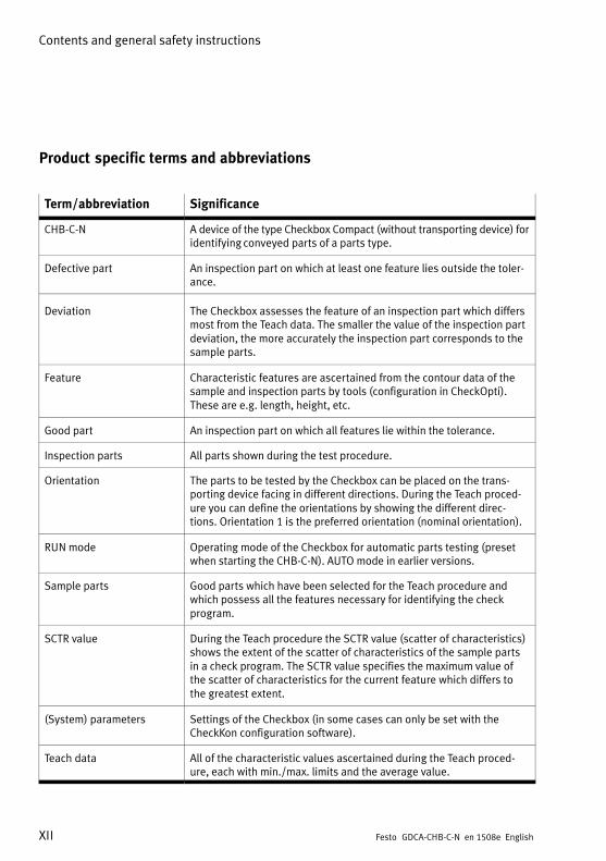
Product specific terms and abbreviations
Term/abbreviation Significance
CHB-C-N A device of the type Checkbox Compact (without transporting device) foridentifying conveyed parts of a parts type.
Defective part An inspection part on which at least one feature lies outside the tolerance.
Deviation The Checkbox assesses the feature of an inspection part which differsmost from the Teach data. The smaller the value of the inspection partdeviation, the more accurately the inspection part corresponds to thesample parts.
Feature Characteristic features are ascertained from the contour data of thesample and inspection parts by tools (configuration in CheckOpti).These are e.g. length, height, etc.
Good part An inspection part on which all features lie within the tolerance.
Inspection parts All parts shown during the test procedure.
Orientation The parts to be tested by the Checkbox can be placed on the transporting device facing in different directions. During the Teach procedure you can define the orientations by showing the different directions. Orientation 1 is the preferred orientation (nominal orientation).
RUN mode Operating mode of the Checkbox for automatic parts testing (presetwhen starting the CHB-C-N). AUTO mode in earlier versions.
Sample parts Good parts which have been selected for the Teach procedure andwhich possess all the features necessary for identifying the checkprogram.
SCTR value During the Teach procedure the SCTR value (scatter of characteristics)shows the extent of the scatter of characteristics of the sample partsin a check program. The SCTR value specifies the maximum value ofthe scatter of characteristics for the current feature which differs tothe greatest extent.
(System) parameters Settings of the Checkbox (in some cases can only be set with theCheckKon configuration software).
Teach data All of the characteristic values ascertained during the Teach procedure, each with min./max. limits and the average value.

Contents and general safety instructions
XIIIFesto GDCA-CHB-C-N en 1508e English
Term/abbreviation Significance
Teach procedure During the Teach procedure, sample parts on the transporting deviceare shown to the Checkbox and the features are scanned. This is alsoreferred to as “Teaching parts”.
Test data The test data is the data used for the test. These correspond to theTeach data plus admitted tolerances.
Test procedure During the test procedure, inspection parts on the transporting deviceare shown to the Checkbox and graded according to their featureswith regard to orientation and observance of the tolerances. This isalso referred to as “Testing parts”.
TEACH mode Operating mode of the Checkbox in which the Teach procedure is carried out.
Test program Program with tools defined by the teach data of the sample parts(configuration in CheckOpti).
Tolerance Factor in per cent related to the average values and which affects themin./max. limits of all features.
Tab. 0/2: Terms and abbreviations

Contents and general safety instructions
XIV Festo GDCA-CHB-C-N en 1508e English

System overview
1-1Festo GDCA-CHB-C-N en 1508e English
System overview
Chapter 1

1. System overview
1-2 Festo GDCA-CHB-C-N en 1508e English
Contents
1. System overview 1-1. . . . . . . . . . . . . . . . . . . . . . . . . . . . . . . . . . . . . . . . . . . . . . .
1.1 The Festo Checkbox 1-3. . . . . . . . . . . . . . . . . . . . . . . . . . . . . . . . . . . . . . . . . . . . .
1.2 Software package 1-4. . . . . . . . . . . . . . . . . . . . . . . . . . . . . . . . . . . . . . . . . . . . . . .
1.3 Function range 1-5. . . . . . . . . . . . . . . . . . . . . . . . . . . . . . . . . . . . . . . . . . . . . . . . .
1.4 Operational principle 1-6. . . . . . . . . . . . . . . . . . . . . . . . . . . . . . . . . . . . . . . . . . . .
1.5 Buffer zone 1-9. . . . . . . . . . . . . . . . . . . . . . . . . . . . . . . . . . . . . . . . . . . . . . . . . . . .

1. System overview
1-3Festo GDCA-CHB-C-N en 1508e English
1.1 The Festo Checkbox
The Festo Checkbox ® enables the optical (contactless) positioning and quality inspection of conveyed parts and it precisely controls the actuators for sorting the inspected partsand parts assigned to the result groups (tracking, ejection ofparts, etc.).

1. System overview
1-4 Festo GDCA-CHB-C-N en 1508e English
1.2 Software package
Various software packages are available for user-friendlycommissioning, optimizing and monitoring.
Software package
Functions
CheckKonCheckbox configurator
– Displaying and evaluating the most recentlyregistered test part
– Displaying and logging of the parts contouras well as the characteristics derived fromthe contour
– Displaying the light intensity recognized bythe camera
– Displaying and printing out of the systemconfiguration
– Displaying and modifying the system parameters
– Support in project planning, managementand documentation
CheckOptiCheckboxoptimizer
– Convenient teaching of the sample parts– Monitored checking of parts, displaying the
registered features– Evaluation of the inspection of workpieces
with regard to reliability (evaluation)– Graphic display of the test sequence– Optimization of the inspection of work
pieces through manual adaptation of themin./max. values of the Teach data orthrough additional tools
– Support in project planning, managementand documentation
Festo Field DeviceTool (FFT)
– Loading a new operating system– Changing network settings (IP address)
Tab. 1/1: Software package
The software package, operating system updates and currentproduct information on the Checkbox Compact can be foundon the Festo website at www.festo.com/sp.

1. System overview
1-5Festo GDCA-CHB-C-N en 1508e English
1.3 Function range
Function
Teach function– Teaching new parts without programming– Saving the features of the taught check program
Quality inspection 1)
– Testing the quality, e.g. with pivoted parts and milling parts– Machine-sorting of incorrect and foreign parts
Position detection (nominal orientation)– Position-controlled transfer of the good parts to the following machine– Return of incorrectly oriented good parts to the small parts conveyorA check of the position and of the buffer zone can be made at the same time.
Buffer zone checkMonitoring the buffer zone with one sensor. If the buffer zone is full: Return of the good parts to the small parts conveyor.If the conveyed parts form a jam on the buffer zone for a long period, the small parts conveyor will beswitched off.
Buffer zone check with switching hysteresis 2)
– Monitoring of the buffer zone with two sensors for delayed switching of the small parts conveyor(hysteresis).
Good part counting with preselected number of items 2)
A continuously running counter ascertains the sum of all good parts– Supplying of defined amounts of components through specification of a target number for good
parts.
1) Extended quality inspection with CheckOpti2) The system parameters must be activated or set in CheckKon
Tab. 1/2: Function range

1. System overview
1-6 Festo GDCA-CHB-C-N en 1508e English
1.4 Operational principle
123
4
5
6
1 Small parts conveyor e.g. vibration feeder, centrifuge, step feeder
2 Return of incorrectly oriented parts to the small parts conveyor
3 Sorting out defective parts (faulty parts, foreign parts)
4 Further transfer of good parts to a buffer zone or the next machine
5 Actuators e.g. exhaust valves
6 Transporting device e.g. conveyor belt, linear axis
Fig. 1/1: Integration of the Checkbox in a transporting device:Example with conveyor belt and two actuators

1. System overview
1-7Festo GDCA-CHB-C-N en 1508e English
The function principle of the Checkbox is based on
– The contactless recognition of small parts
– The teaching of new parts without programming
– An integrated quality inspection.
Identification A small parts conveyor separates the conveyed parts andpasses them on to the transporting device. The transportingdevice (e.g. conveyor belt, linear axis) can be fitted with amaximum of 4 actuators for returning or separating the conveyed parts.
The Checkbox registers each part in contour pictures. Fromthe contours the system ascertains part-specific featuressuch as length, height and surface. On the basis of the features the Checkbox recognizes:
– The orientation
– The dimensional accuracy
– The quality.
Teaching The nominal contour of a conveyed part is ascertained by asimple procedure:
1. You “show” the Checkbox samples of the conveyed parttype several times one after the other (= scan) in the nominal orientation.
2. You scan the sample parts in further orientations if required.
3. You save the features of the check program as Teach data.
4. You test the Teach data in the test mode.

1. System overview
1-8 Festo GDCA-CHB-C-N en 1508e English
Testing Each registered conveyed part is compared with the savedTeach data and then sorted into different types. The test partsare separated basically via 3 conveying paths:
– Good parts are passed on e.g. to an assembly system.
– Incorrectly oriented parts are returned to the small partsconveyor.
– Faulty or foreign parts (defective parts) are rejected.

1. System overview
1-9Festo GDCA-CHB-C-N en 1508e English
1.5 Buffer zone
The buffer zone serves as a parts buffer for the next machinee.g. an assembly system.
The Checkbox can monitor the highest and lowest fillingstates of the buffer zone and if the jam of parts is long, it canswitch the small parts conveyor on or off as required. (Bufferzone check, see Fig. 1/2).
Additionally by means of a second sensor, the small partsconveyor can be switched to delay. (Buffer zone check withhysteresis, see Fig. 1/3).
Signal delay
The buffer zone inputs are processed by the Checkbox with adebounce time. This time delay is configurable. The sensorsignal is only then evaluated if it is present for the duration ofthe configured time delay. This delay prevents each conveyedpart from triggering the signal “Buffer zone full” when itpasses the sensor.
The delay time between the detection of a conveyed part bythe sensor and the interpretation of the signal by the Checkbox must be taken into account when the buffer zone sections are planned.
Dimensioning the buffer zone
The buffer zone sections (see Fig. 1/2) must be dimensionedso that uninterrupted operation of the machine is possible.Instructions on dimensioning the buffer zone can be found inthe following table.

1. System overview
1-10 Festo GDCA-CHB-C-N en 1508e English
Dimensioning the buffer zone sections
A Section between the transporting device and the sensor.Section A must accept all conveyed parts which liebetween the Checkbox and the sensor when a conveyedpart has been registered by the sensor. The length depends on:– The geometry of the conveyed parts– The maximum feeder rate of the small parts conveyor– The length of the transporting device
B Section between the sensor and the next machine.When the small parts conveyor is switched on again, uninterrupted operation of the assembly system must beguaranteed until the first new conveyed parts arrive.Section B must be designed so that a sufficient number ofconveyed parts can be made available. The length depends on:– The geometry of the conveyed parts– The maximum time delay between switching on the
small parts conveyor again and making the new conveyed parts available
– The length and speed of the transporting device– The average feed amount of good parts in the nominal
orientation– - The cycle rate of the machine
AB*) Section between sensors 1 and 2 (Fig. 1/3).Section AB determines the switching delay (hysteresis) ofthe small parts conveyor for regulating the supply ofparts. The longer the section is, the less the switchingfrequency.
*) Set the “Number of buffer zone sensors = 2” with CheckKon
Tab. 1/3: Buffer zone sections
Also observe Chapter 3.3 and Chapter 3.6.5 when connectingthe buffer zone sensors.

1. System overview
1-11Festo GDCA-CHB-C-N en 1508e English
1 Transportingdevice
2 Sensor 1
1
A
B
2
Fig. 1/2: Buffer zone check
1 Transportingdevice
2 Sensor 2
3 Sensor 1
A
B
AB
3
2
1
Fig. 1/3: Buffer zone check with hysteresis

1. System overview
1-12 Festo GDCA-CHB-C-N en 1508e English

Mounting and commissioning
2-1Festo GDCA-CHB-C-N en 1508e English
Mounting and commissioning
Chapter 2

2. Mounting and commissioning
2-2 Festo GDCA-CHB-C-N en 1508e English
Contents
2. Mounting and commissioning 2-1. . . . . . . . . . . . . . . . . . . . . . . . . . . . . . . . . . . .
2.1 General instructions 2-3. . . . . . . . . . . . . . . . . . . . . . . . . . . . . . . . . . . . . . . . . . . . .
2.2 Mounting 2-5. . . . . . . . . . . . . . . . . . . . . . . . . . . . . . . . . . . . . . . . . . . . . . . . . . . . . .
2.3 Electrical connection 2-9. . . . . . . . . . . . . . . . . . . . . . . . . . . . . . . . . . . . . . . . . . . .
2.3.1 Selecting the power supply unit 2-15. . . . . . . . . . . . . . . . . . . . . . . . . . . .
2.3.2 Connection of the operating voltage 2-16. . . . . . . . . . . . . . . . . . . . . . . .
2.3.3 Power supply for external components 2-17. . . . . . . . . . . . . . . . . . . . . .
2.4 Adapting system parameters with CheckKon 2-18. . . . . . . . . . . . . . . . . . . . . . . . .
2.5 Commissioning the Checkbox 2-20. . . . . . . . . . . . . . . . . . . . . . . . . . . . . . . . . . . . .
2.6 Error diagnostics 2-27. . . . . . . . . . . . . . . . . . . . . . . . . . . . . . . . . . . . . . . . . . . . . . .

2. Mounting and commissioning
2-3Festo GDCA-CHB-C-N en 1508e English
2.1 General instructions
WarningRisk of injury
� During operation, make sure that no danger is causedby the controlled peripheral equipment
CautionRisk of injury, damage to components
� When removing from the packaging, make sure nothingcan fall
� When mounting and removing, make sure nothing can fall
� Only carry out commissioning procedures when fullymounted
CautionDamage to components.
� Before carrying out mounting, installation and/or maintenance work, always switch off the power supply.

2. Mounting and commissioning
2-4 Festo GDCA-CHB-C-N en 1508e English
CautionGlare and eye irritation.
� Do not remove any housing parts.
� Only mount/remove the prism support when the powersupply is switched off
� Mount the Checkbox only in its original state withclosed, intact housing.
� Mount or remove the Checkbox only when the powersupply is switched off.
� Mount the Checkbox in such a way that it is not possibleto look directly into the light beam.
� Also take measures to ensure that if the light beam isreflected off mirrored or reflective objects, it does notpose a hazard (for example, by providing screening).
� Do not stare directly into the light beam and do not direct the beam into the eyes of other people.
1 Prism support
2 Opening for thelight beam
1
21
Fig. 2/1: Lighting

2. Mounting and commissioning
2-5Festo GDCA-CHB-C-N en 1508e English
2.2 Mounting
Transport Always transport the Checkbox in its original packing; furthertransport safety measures are not necessary.
Mounting location Please observe the following ambient conditions in particular:
– The mounting location must be free of vibration
– There must be stable mechanical fastening
– Clean ambient atmosphere: Free of oil, no paint spray, nogrinding dust
– Screening of external light influences, external heat andextreme magnetic fields (e.g. due to induction furnaces).
– The mounting position should be as cool and vertical aspossible
In this way you will achieve optimum test results and ensurea long service life of the device.
Temperature A built-in temperature sensor protects the device. The permissible ambient temperature relates to a 1 A load at theoutputs; with a 3 A load approx. 5 °C lower is permissible.The maximum ambient temperature depends on a variety ofparameters, e.g. parts rate, mounting method, thermal radiation, input and output circuitry, supply voltage, etc.
Transporting device In order to ensure a reliable and reproducible test result, thetransporting device used should fulfill the following requirements:
� Use a high-grade transporting system which conveys theparts at a constant speed.
� Ensure the stable position of the parts, e.g. by means ofmechanical devices.
� Ensure a good transfer of parts from the small parts conveyor to the transporting device and that the transportingdevice is mechanically decoupled from the small partsconveyor.

2. Mounting and commissioning
2-6 Festo GDCA-CHB-C-N en 1508e English
� Also use mechanical devices to secure the transfer ofparts from the transporting device to the buffer zone (e.g.drop pipe, slide, chute) of the subsequent machine sothat the orientation of parts cannot be subsequentlychanged.
Space requirement Observe the space required for installation of the Checkbox.The dimensions of the Checkbox and specifications on weightcan be found in the appendix A.5.
Mounting A mounting profile with dovetail guide is attached to the sideof the Checkbox. If you want to mount the Checkbox from theother side, remove the profile and attach it to the oppositeside of the Checkbox.
CautionDamage to components.
� Only modify the Checkbox in a clean environment
� Only use suitable screws. The screw-in depth in thedevice is limited to a maximum of 6 mm.
A connecting kit (type HMSV-12) is available as an accessoryfrom Festo.

2. Mounting and commissioning
2-7Festo GDCA-CHB-C-N en 1508e English
1 Mounting profileof the Checkbox
2 Clamping elements with 4M5x45 sockethead screws
3 2 M5x16 sockethead screws withcentring sleeves
4 Adapter plate
1
2
3
4
Fig. 2/2: Mounting the Checkbox with connecting kit HMSV-12
Mount the Checkbox over the transporting device so that:
– The Checkbox and transporting device are mounted securely to each other (Fig. 2/3)
– The field of view of the camera is not impeded
– The optical channel is not covered by the transportingdevice
The Checkbox Compact has excellent imaging properties overthe entire working space. The contrast of the image is optimised for very fine details on the sensor side.
– To achieve maximum contrast for small details, mount thedevice in such a way that the objects are passed as closeas possible to the prism support on the sensor side. Thisis the side with the Start/Stop button.

2. Mounting and commissioning
2-8 Festo GDCA-CHB-C-N en 1508e English
1 Mounting profile
2 Optical channelof the camera
3 Glass surface onthe prism support (opening forlight beam)
1
3
2
2
Fig. 2/3: Arrangement of the Checkbox over the transporting device (example)
NoteIn order that a reliable test result can be achieved, theglass surfaces on the prism supports must not be scratched or dirty:
� Mount the Checkbox so that passing parts do not touchthe glass surfaces.
� Ensure the stable position of the parts, e.g. by means ofmechanical devices.
� If necessary, clean the glass surfaces, as described inchapter 6

2. Mounting and commissioning
2-9Festo GDCA-CHB-C-N en 1508e English
2.3 Electrical connection
1 Reserved forFesto service
2 Buffer/Feeder
3 Actuators
4 Encoder
5 24 V DC
6 PLC
7 Ethernet
8 FE
1 2 3 4 5 6 7 8
Fig. 2/4: Connections of the Checkbox
Function Chapter
1 – Connection for Festo Service
2 – Connection of 1 buffer zone sensor for controlling the flow of parts to the nextmachine
– 24 V power outputs for controlling the supply system (small parts conveyor) andthe transport system (transporting device)
3.3
3 – 24 V power outputs for controlling a maximum of 3 actuators for sorting out thetested conveyed parts
3.2
4 – Connection of a rotary pulse generator for determining the speed of the conveyorsystem with increased demands for length accuracy
3.5
5 – Connection for the 24 V DC operating voltage 2.3.2
6 – Connection of 2 buffer zone sensors for controlling the flow of parts to the nextmachine
– 24 V power output for controlling the supply system (small parts conveyor) andthe transporting device
– I/O signals for process monitoring and higher-order control or for controlling adownstream-switched machine
3.6

2. Mounting and commissioning
2-10 Festo GDCA-CHB-C-N en 1508e English
Function Chapter
7 – Connection of a diagnostic PC for system diagnosis, visualizing and optimizingthe test procedure with the software packages CheckKon and CheckOpti
3.4
8 – Functional earth connection 2.3
Caution� Check within the framework of your EMERGENCY STOP
concept to ascertain the measures necessary for puttingyour machine/system into a safe state in the event of anEMERGENCY STOP (e.g. switching off the operatingvoltage, switching off pressure).
Preparing plugs and cables
Use plugs and sockets from the Festo supply programmewhich match the outer diameter of the cables used(www.festo.com/catalogue).
NoteAngled connectors can transfer large forces into the device. This can lead to mechanical destruction of the electronics.
� When using angled connectors pay particular attentionto ensure that no excessive force is exerted on the connections. Attach cables in such a way that only minorforces are exerted on the connections of the Checkbox.

2. Mounting and commissioning
2-11Festo GDCA-CHB-C-N en 1508e English
NoteTo avoid malfunctions from electromagnetic interference:
� You can use unscreened cables up to 30 m in length foractuators and buffers.
� Only use screened cables and plug connectors for allother connections.
� Provide potential equalisation when connecting components via screened cables. The cable screening andscreen connections of the Checkbox are not intended tocarry compensating current caused by potential differences.
� Use large-cross-section cable that is as short as possible.
� Connect both the FE earth terminal and the cable screening with low impedance to the earth potential.
� At the FE connection on the front panel, use an earthingstrap with a suitable cross section.

2. Mounting and commissioning
2-12 Festo GDCA-CHB-C-N en 1508e English
NoteTo avoid damaging the device as a result of a voltageovershoot when switching on, please observe the following:
� Power supply is only permitted with round cables; donot use single wires.
� To avoid voltage overshoots when connecting to lowimpedance supplies, please pay attention to the lowerinductance of the supply cable.
� To ensure optimum attenuation of the voltage overshoot, the supply cable should not be of too low an impedance. Festo therefore recommends a cross section of1.0 or 1.5 mm²
� Observe the maximum load capacity of the cable.
� Safeguard the supply cable appropriately. Do not exceedvalues in data sheets. Only use regulated power supplyunits. First establish the secondary-side connection,then switch on the power supply unit on the primaryside. Do not connect to sources when powered.

2. Mounting and commissioning
2-13Festo GDCA-CHB-C-N en 1508e English
NoteFor general protection of the device, and to avoid overloading the GND pins of the interfaces in particular, pleaseobserve the following:
� Do not connect any outputs in parallel.
� Do not feed any voltage into the outputs; this will annulthe internal current monitoring function; if polarity reversal occurs, there is a risk that the device will be destroyed.
� Only use the GND connection of the respective plug connector or the GND of the power supply unit as the GND.
� Do not return any of the output signals at the PLC, actuator or buffer plug connector to the GND of one of theother output connectors.
� If an overload occurs, the outputs will be switched off.This also applies, if applicable, to the outputs “Error”and “Warning” of the PLC interface (see chapter 3.6).These are only intended for diagnostic purposes. Toidentify the operating status use the “Ready for operation” signal that operates with reverse logic. If an erroroccurs, this is switched off. As a result, an external control system could identify the error.
� When connecting inductive loads (solenoid coils, valves,contactors, relays, etc.), an appropriate RC element(free-wheeling diode, RC snubber, varistor, etc.) must beprovided directly on the load.
� Select appropriate plug connectors and cables as well assuitable cross sections. Do not overload the cables.
Cable outside diameter Plugs/sockets
4.0 ... 6.0 mm PG 7
6.0 ... 8.0 mm PG 9
10.0 ... 12.0 mm PG 13.5
Tab. 2/1: Cable outside diameter

2. Mounting and commissioning
2-14 Festo GDCA-CHB-C-N en 1508e English
Connection Plugs/sockets
Power supply socket PG 9 or PG 13.5
Sensors, actuators PG 7
Tab. 2/2: Connection
In order to guarantee observance of the IP protection classfor the completely fitted Checkbox:
� Tighten the union nuts of the plug connectors by hand.
� Seal unused sockets with the protective caps supplied.
CautionLong I/O signal lines reduce the resistance to interference.
� Comply with the maximum permissible I/O signal linelength of 30 m.

2. Mounting and commissioning
2-15Festo GDCA-CHB-C-N en 1508e English
2.3.1 Selecting the power supply unit
WarningElectric shock
Injury to people, damage to the machine and system
� Only use PELV circuits in accordance with IEC 60204-1(protective extra-low voltage, PELV) for the electricalpower supply.
� Observe the general requirements of IEC 60204-1 forPELV circuits.
� Use only voltage sources that guarantee a reliable electric separation of operating and load voltage in accordance with IEC 60204-1.
Make sure the power supply unit fulfils the requirements specified in the Checkbox data sheet with regard to voltage, current and power.
Allow for a sufficient power reserve.
Observe the power consumption of connected consumers aswell as system expansions.

2. Mounting and commissioning
2-16 Festo GDCA-CHB-C-N en 1508e English
2.3.2 Connection of the operating voltage
WarningRisk of fire
� Protect the supply cable with a 4 A fast-acting fuse.
� Use an operating voltage cable with a suitable cable crosssection.
� Avoid long distances between the power supply unit andthe Checkbox. Long operating voltage cables reduce thevoltage supplied by the power supply unit.
Connect the Checkbox to the operating voltage as follows:
Pin 24 V DC connector plug
1 Do not connect
2 +24 V DC, -15 % + 20 %; protectwith 4 A fast-acting fuse
3 GND
4 FE
Tab. 2/3: 24 V DC plug connector
Use only a 4-pin M18 socket for the power supply and connect this only to the connection for the power supply.
1. Connect the plug to the 24 V DC connection on the Checkbox.
2. Tighten the union nuts of the plug by hand.

2. Mounting and commissioning
2-17Festo GDCA-CHB-C-N en 1508e English
2.3.3 Power supply for external components
When connecting the Checkbox to other devices (e.g. PLC,conveyor device) via the connections PLC, ACTUATORS orBUFFER/FEEDER, do not connect the potential at the“24 V DC” connection of the Checkbox with other plug connectors of the Checkbox.
Current-consuming devices can also be supplied with voltagevia the PLC plug. Observe also the information in chapter 3.6.

2. Mounting and commissioning
2-18 Festo GDCA-CHB-C-N en 1508e English
2.4 Adapting system parameters with CheckKon
A password is required for CheckKon for setting the systemparameters and transmitting the modifications to the Checkbox (function “Modify system”). Consult your Festo Service.
� Install CheckKon on your diagnostic PC. Installation instructions can be found in the software description.
Diagnostic mode Start CheckKon after switching on the Checkbox. CheckKonswitches the Checkbox to the diagnostic mode.
NoteIn the diagnostic mode the Checkbox transmits additionalinformation via the Ethernet interface.
� Do not operate the Checkbox in diagnostic mode withthe full rate of parts.
In this way you can prevent parts from passing the actuator positions unchecked.
1. Adapt the Checkbox to your system requirements with thesystem parameters in the menu [View] [System parameter].Also observe the instructions in the following chaptersand in the software description.
2. Adapt other device settings with CheckKon accordingly,such as date and time of the device.
CheckKon shows the most important system parametersthrough the menu [View] [System parameter] symbol “Onlyimportant parameters”. Make sure that these parametersare adapted to your application.
3. Transfer the modified settings to the Checkbox (see software description).
4. Conclude CheckKon and with it the diagnostic mode whenall settings have been completed.

2. Mounting and commissioning
2-19Festo GDCA-CHB-C-N en 1508e English
NoteFaulty processing data can cause incorrect functioning ofthe Checkbox.
� Carry out the complete Teach procedure again if youhave modified the system parameters with CheckKon(see chapter 4).
2. Mounting and commissioning
2-20 Festo GDCA-CHB-C-N en 1508e English
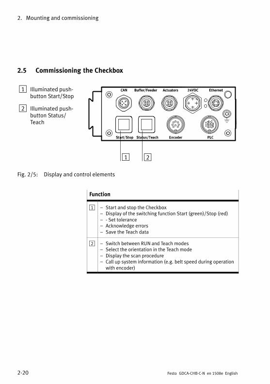
2.5 Commissioning the Checkbox
1 Illuminated pushbutton Start/Stop
2 Illuminated pushbutton Status/Teach
21
Fig. 2/5: Display and control elements
Function
1 – Start and stop the Checkbox– Display of the switching function Start (green)/Stop (red)– - Set tolerance– Acknowledge errors– Save the Teach data
2 – Switch between RUN and Teach modes– Select the orientation in the Teach mode– Display the scan procedure– Call up system information (e.g. belt speed during operation
with encoder)

2. Mounting and commissioning
2-21Festo GDCA-CHB-C-N en 1508e English
Before the Checkbox is switched on the first time, make surethat you have completed the following steps:
1. Mounting of the transporting device
2. Mounting of the Checkbox on the transporting device
3. Pin 4 FE/PE connected to the 24 V DC connection in aprofessional manner
4. Connection of external components, if requiredObserve the instructions on connecting external components in the following chapters:
– Chapter 3.2 “Actuators”
– Chapter 3.3 “Buffer/Feeder”
– Chapter 3.5 “Encoder”
– Chapter 3.6 “PLC”
WarningCheck to see which measures are necessary for puttingyour machine/system in a safe state when it is switched onand off. Sudden unexpected movements of the connectedactuators can cause personal injury and damage toproperty if e.g.
� the transporting device is moved to its initial positionwhen the power supply is switched off,
� the transporting device starts automatically if controlledby the Checkbox when the Checkbox starts.
In order to prevent the transporting device from startingautomatically when the operating voltage is switched on,observe the following:
� Select in CheckKon [View] [System parameter] � System� Operating modes � Automatic start after power supply on = no (factory setting).

2. Mounting and commissioning
2-22 Festo GDCA-CHB-C-N en 1508e English
Switching on 1. Switch on the operating voltage for the Checkbox via thepower unit.
2. Start CheckKon in order to display and set the systemparameters (see chapter 2.4).
3. Start the transporting device manually if necessary.
Fig. 2/6: STOP status
– Readiness to operate is signaled by the STOP status
– The IP address (factory setting: 192.168.2.20) indicatesthe current IP address of the device
– CHB-C-N firmware version number (3.5.3)(Hash value of the firmware version 1b95f81806a6)

2. Mounting and commissioning
2-23Festo GDCA-CHB-C-N en 1508e English
Teach mode Scan the sample parts in the Teach mode in order to recordthe Teach data (see chapter 4).
Fig. 2/7: Teach mode
– Tol.: Tolerance (5) indicates the standard tolerance value(= 5 %) for the selected check program
– Ori.: Orientation (1) indicates the orientation of thesample part to be taught
– Sctr: Scatter of characteristics (110) indicates the maximum value for the scatter of characteristics
– Prog: Check program number (1)
– Check program name (Name 1) indicates the numberand name of the selected check program

2. Mounting and commissioning
2-24 Festo GDCA-CHB-C-N en 1508e English
NoteThe following list provides only an overview of the mostimportant operating steps. Note the instructions on theTeach procedure in chapter 4, before starting the Checkbox in the Teach mode.
The Checkbox is ready to operate as soon as it is switched on(STOP status).
1. Press the Status/Teach button. Scan sample parts of check program 1 in orientation 1.The “SCTR” value of the scatter of characteristics will beshown during the scanning process (e.g. 30)
2. Press the Status/Teach button. Scan sample parts in the next orientation (2).Repeat the procedure for further orientations.
3. Press the Start/Stop button.The Teach data is saved and the Teach mode is concluded.

2. Mounting and commissioning
2-25Festo GDCA-CHB-C-N en 1508e English
RUN mode Evaluate the reliability of the Teach data before starting theautomatic parts test.
Fig. 2/8: RUN mode
NoteThe following list provides only an overview of the mostimportant operating steps.
� Note the instructions on the test procedure in chapter 5,before starting the Checkbox in the RUN mode.
The Checkbox is ready to operate (STOP status)
1. Press the Start/Stop buttonPresetting: Check program 1; tolerance 5 % (for influenceand setting the tolerance, see chapter 5.3).
2. Check the inspection part deviation “Dev” and the inspection part orientation “Ori” (see chapter 5.4).
3. If necessary, correct the system settings with CheckKon.Only modify system parameters/system data if the Checkbox is in its STOP status.
4. Conclude CheckKon when all the settings have been completed.

2. Mounting and commissioning
2-26 Festo GDCA-CHB-C-N en 1508e English
NoteFaulty processing data can cause incorrect functioning ofthe Checkbox.
� Carry out the complete Teach procedure again if youhave modified the system parameters with CheckKon.
Switching off Switch the Checkbox to the STOP status before switching it off:
1. Press the Start/Stop button.
2. Switch off the operating voltage.

2. Mounting and commissioning
2-27Festo GDCA-CHB-C-N en 1508e English
2.6 Error diagnostics
The Checkbox indicates operating errors as follows:
– The Checkbox switches automatically to the STOP status.
– The illuminated pushbuttons on the Checkbox flash.
– The display shows the error code “Error” including anexplanation in English (for an overview of the types oferror see appendix A1).
Fig. 2/9: Example: Error message “Error 5”
– ERROR error number (5)
– The error description (Material jam) provides a brief textual description for the corresponding error number andinformation concerning remedial measures
Pushbutton
Status Significance
Start/Stop
Status/Teach
Flashes red
Flashes yellow
Error message / warning
Tab. 2/4: Error display

2. Mounting and commissioning
2-28 Festo GDCA-CHB-C-N en 1508e English
The Checkbox cannot be started again until the fault has beeneliminated:
1. Eliminate cause of malfunction
2. Acknowledge error message: Press the Start/Stop button
3. Start Checkbox: Press the Start/Stop button
Additional information:
– Details on the fault codes and instructions on eliminatingfaults can be found in appendix A.1.
– The CHB-C-N also signals faults at the PLC connection viaO/17 (error) and, if applicable, O/23 (warning) (seechapter 3.6.6).

I/O module
3-1Festo GDCA-CHB-C-N en 1508e English
I/O module
Chapter 3

3. I/O module
3-2 Festo GDCA-CHB-C-N en 1508e English
Contents
3. I/O module 3-1. . . . . . . . . . . . . . . . . . . . . . . . . . . . . . . . . . . . . . . . . . . . . . . . . . . .
3.1 Interfaces 3-3. . . . . . . . . . . . . . . . . . . . . . . . . . . . . . . . . . . . . . . . . . . . . . . . . . . . .
3.2 Actuators 3-5. . . . . . . . . . . . . . . . . . . . . . . . . . . . . . . . . . . . . . . . . . . . . . . . . . . . .
3.3 Buffer/Feeder 3-8. . . . . . . . . . . . . . . . . . . . . . . . . . . . . . . . . . . . . . . . . . . . . . . . . .
3.4 Ethernet interface 3-12. . . . . . . . . . . . . . . . . . . . . . . . . . . . . . . . . . . . . . . . . . . . . . .
3.5 Encoder 3-16. . . . . . . . . . . . . . . . . . . . . . . . . . . . . . . . . . . . . . . . . . . . . . . . . . . . . . .
3.6 PLC 3-18. . . . . . . . . . . . . . . . . . . . . . . . . . . . . . . . . . . . . . . . . . . . . . . . . . . . . . . . . . .
3.6.1 Start/Stop mode 3-21. . . . . . . . . . . . . . . . . . . . . . . . . . . . . . . . . . . . . . . .
3.6.2 Selection of the check program 3-23. . . . . . . . . . . . . . . . . . . . . . . . . . . .
3.6.3 Counting function 3-28. . . . . . . . . . . . . . . . . . . . . . . . . . . . . . . . . . . . . . .
3.6.4 Actuators 3-32. . . . . . . . . . . . . . . . . . . . . . . . . . . . . . . . . . . . . . . . . . . . . .
3.6.5 Buffer zone sensors/small parts conveyor 3-34. . . . . . . . . . . . . . . . . . .
3.6.6 Fault messages 3-37. . . . . . . . . . . . . . . . . . . . . . . . . . . . . . . . . . . . . . . . .
3.6.7 Locking the control panel 3-37. . . . . . . . . . . . . . . . . . . . . . . . . . . . . . . . .

3. I/O module
3-3Festo GDCA-CHB-C-N en 1508e English
3.1 Interfaces
1 Buffer/Feeder
2 Actuators
3 Ethernet
4 Encoder
5 PLC
4 5
1 2 3
Fig. 3/1: The I/O module of the CHB-C-N
Function
1 – Connection of 1 buffer zone sensor for controlling the flow ofparts to the next machine
– 24 V power outputs for controlling the supply system (smallparts conveyor) and the transport system (transporting device)
2 – 24 V power outputs of a maximum of 3 actuators for sortingout the tested conveyed parts
3 – Connection of a diagnostics PC for system diagnosis, visualizing and optimizing the test procedure
4 – Connection of a rotary pulse generator for determining thespeed of the conveyor system
5 – Connection of 2 buffer zone sensors for controlling the flowof parts to the next machine
– 24 V power output for controlling the supply system (smallparts conveyor) and the transport system (transportingdevice)
– I/O signals for process monitoring and higher-order controlor for controlling a downstream-switched machine
– Optional fourth actuator output (configuration-dependent)

3. I/O module
3-4 Festo GDCA-CHB-C-N en 1508e English
Power supply Observe the instructions on supplying power to external components in chapter 2.3.3 and chapter 3.6.
For electrical properties of the I/O signals, see Technical data(appendix A.5).

3. I/O module
3-5Festo GDCA-CHB-C-N en 1508e English
3.2 Actuators
NoteTo avoid malfunctions from electromagnetic interference:
� Use cables with a maximum length of 30 m
Connection assignment
Actuators connection socket
O/1 Actuator 3
1
43
25
O/2 Actuator 2
3 GND
O/4 Actuator 1
5 Do not connect
Tab. 3/1: 24 V DC plug connector
Position of the actuators
The arrangement of the actuator positions and their allocation is to be planned in such a way that ensures proper segregation of the tested parts. The actuator positions and theirrelative arrangement along the transporting device are to beadapted to the lengths of the tested parts and the inspectiontask.
If a part has already passed an actuator position before theassignment according to the inspection result is present, theCHB-C-N changes to its error state.
Despite an apparently correct configuration of the actuatorpositions, it may be the case that good parts are ejected atthe defective parts actuator. A possible cause for this may bean excessively long period of evaluation for the tested part.
3. I/O module
3-6 Festo GDCA-CHB-C-N en 1508e English
To ensure that a defective part cannot accidentally pass theinspection as a good part, all inspection parts are marked asdefective parts directly after the scanning procedure.However, if the subsequent quality calculation takes longerthan the inspection part needs to reach the position of thedefective part actuator, a reassignment to another actuator isno longer possible. In this case, the inspection part is ejectedat the defective part actuator regardless of the quality decision. This also means that the separation of parts in thedisplayed inspection result (on the LCD display and in CheckKon, if connected) deviates from the actually performed separation of parts.
Controlling the actuators
NoteIf there is a failure in the power supply to the CHB-C-N orto the actuators when the transporting device is running,this can result in:
� Parts passing the actuator positions unchecked
� The actuators being unable to sort out checked parts.
Check the measures which are required on your machine/system in order to prevent incorrectly oriented parts ordefective parts from unintentionally reaching the next machine in the event of such operating faults.
Input I/19 is provided on the PLC connector to monitor thepneumatic supply for the actuators. An “External error”,which switches the Checkbox to its error state, can betriggered via this input.
The CHB-C-N can control up to four actuators for sorting outgood parts, incorrectly oriented parts and defective parts.Possible actuators are e. g. shunts, reversing stations or airnozzles which sort out the parts at certain positions on thetransporting device depending on the inspection result. Thenumber and assignment of the actuator positions may vary

3. I/O module
3-7Festo GDCA-CHB-C-N en 1508e English
depending on application. The assignment of the actuatorpositions can be adapted with the CheckKon software.
Example configuration: Transporting device with 2 blow-outnozzles (see Fig. 1/1)
The compressed air valves of the blow-out positions must beconnected directly with the outputs for actuators 1...2. Theseoutputs are set to + 24 V DC if the parts test delivers the following result:
– Incorrectly oriented or superfluous (good) part
– Defective or foreign part
If the CHB-C-N recognizes an inspection part as a good part,the signal actuator 3 will be set from the rest potential 0 V to+ 24 V DC and the good part will be output at the end of thetransporting device.
Output Signal level 1) (example configuration)
Actuator 1 The + 24 V DC signal is present when the inspectionpart passes the actuator position for incorrectlyoriented or superfluous good parts.
Actuator 2 The + 24 V DC signal is present when the inspectionpart passes the actuator position for defective orforeign parts.
Actuator 3 The + 24 V DC signal is present when the inspectionpart passes the actuator position for good parts(here: The end of the transporting device).
Actuator 4 Optionally available on the PLC interface (configuration-dependent: Actuator / counter readingreached)
1) The duration of the signal corresponds to the time required for thepart to reach the air jet nozzle.

3. I/O module
3-8 Festo GDCA-CHB-C-N en 1508e English
3.3 Buffer/Feeder
NoteTo avoid malfunctions from electromagnetic interference:
� Use cables with a maximum length of 30 m
Connection assignment
BUFFER/FEEDER connector socket
O/1 24 V DC / Box ready– Reference voltage for sensors
(switched off in Stop status)– Operating status– Control for transporting device (e.g.
conveyor belt)
1
43
25
O/2 FeederControl of the small parts conveyor (e.g.upstream feeder bowl)
3 GNDReference voltage for sensors
I/4 BufferBuffer zone sensor 1
5 Do not connect
Tab. 3/2: BUFFER/FEEDER connector socket
Direct connection can also be made with a Festo Duo cable(accessories � www.festo.com/catalogue).
Identification of the Duo cable
Signal x Buffer zone sensor 1
Signal x + 1 Small parts conveyor (feeder)

3. I/O module
3-9Festo GDCA-CHB-C-N en 1508e English
Controlling the small parts conveyor (feeder)
To enable controllers of small parts conveyors with a 24 V DCenable input to switch the conveyor device on and off:
1. Connect the output pin O/2 and GND, pin 3 of the buffer/feeder connector to the enable input.
2. Select the function Active = On = 24 V DC on the controller.
3. Connect the buffer zone sensor to the Checkbox at inputI/4 and GND of the buffer/feeder connector.
Controlling the buffer zone sensor (buffer)
If the buffer zone sensor is triggered in the run mode, “BUF”will appear in the display.
Fig. 3/2: Buffer zone full
� BUF signals the status “Buffer zone full”
� If the buffer zone is emptied, “BUF” will disappear fromthe display

3. I/O module
3-10 Festo GDCA-CHB-C-N en 1508e English
NoteOnly in this way is the Checkbox ready to operate:
� Leave unused sensor inputs open if the buffer zonesensor inputs have been configured according to thedefault settings.
Otherwise, the display will show the operating status“BUF”, although the buffer zone is free. All good parts willbe returned. The small parts conveyor is switched off after30 s (standard setting).
Signal duration In order to avoid unnecessary switching movements, theCheckbox reacts only after a certain signal duration to thesensor signals for “Buffer zone full” and “Buffer zone empty”.
Modification of the signal duration with CheckKon in themenu [View] [System parameter] � System � Transportingsystems � Continuing systems ...� Minimum sensor signalduration for status: Buffer zone full: 1.0 s (0.1 s ... 180 s)Buffer zone empty: 1.0 s (0.1 s ... 180 s)
Sensor type The CHB-C-N is factory preset for use with a buffer zonesensor, the sensor output of which lies at a potential of 0 V(i.e. no conveyed part in front of the sensor) in the rest state.This corresponds to the parameter setting in CheckKon: Buffer zone sensor types = active HIGH (24 V)
NoteYou can optimize the operational safety of your supplysystem as follows:
� Use sensors which have a sensor output with a potentialof 24 V DC in the rest state
� Adapt the setting of the sensor type with CheckKon.
You can then prevent the system from becoming blockede.g. in the event of a broken cable.

3. I/O module
3-11Festo GDCA-CHB-C-N en 1508e English
Modification of the sensor type with CheckKon in the menu[View] [System parameter]: � System � Transporting systems��Continuing systems ...� Buffer zone sensor types
Sensor type FunctionBuffer zone with one sensor
Active HIGH(24 V) 1)
Active LOW(0 V) 2)
Sensor 1LOW
Sensor 1HIGH
The sensor does not register aconveyed part. The small partsconveyor is/remains switched on.
Sensor 1HIGH
Sensor 1LOW
The buffer zone is full. “BUF” appears in the display. Good partsare returned. When the presettime e. g. 30 s has expired, thesmall parts conveyor will beswitched off; the transportingdevice still runs.
1) factory presetting2) to be set with CheckKon
Information on dimensioning the buffer zone can be found inchapter 1.5.

3. I/O module
3-12 Festo GDCA-CHB-C-N en 1508e English
3.4 Ethernet interface
Note� Use a screened cable with a maximum length of 70 m
� Use a screened plug connector to ensure continuouscontact between the screening and the Checkbox.
� Connect the screening of the Ethernet cable with lowimpedance to earth potential.
NoteUnauthorised access to your Checkbox can result indamage or malfunctions.
� Ask your system administrator how you should protectyour network against unauthorized access, e.g. with afirewall.
NoteWith an active connection to the Checkboxes in the network, large amounts of data can be transmitted, depending on the mode of operation. This places a considerableburden on the network between the PC and Checkbox.A direct connection is therefore preferable.
� If in doubt, ask your network administrator whether corresponding band widths are available for you or what anoptimum network structure for you should look like.
� Comply with the necessary system requirements.

3. I/O module
3-13Festo GDCA-CHB-C-N en 1508e English
To commission the Checkbox you will need to create a connection between your PC and the Checkbox via Ethernet.
For special requirements in an industrial environment, use ascreened flexible Ethernet round cable of category 5, whichwill fulfil your requirements as regards resistance to oil,bending radius, permitted bending cycles, etc. Connections:M12 socket, 4-pin, d-coded and RJ45 plug
Ethernet connection The connection to the PC and displays or higher-order controllers can be established via the Ethernet interface. To permit a connection, several prerequisites with regard to thedevice’s network address and the PC must be fulfilled.
The network properties of the device can be adapted usingthe Festo Field Device Tool (FFT). Factory setting of the IP address: 192.168.2.20.
Pin Signal M12 Ethernet connection socket 1)
1 TD+ Transmitted data +
1
4
2
3
2 RD+ Received data -
3 TD- Transmitted data –
4 RD- Received data –
Metal covering Screening (shield)
1) d-coded
Tab. 3/3: Pin allocation of the Ethernet interface
The Ethernet interface of the Checkbox complies with thestandards 10BaseT/100BaseTX for 100 Mbit/s networks.

3. I/O module
3-14 Festo GDCA-CHB-C-N en 1508e English
LED Status Description
Green (speed) 10Base-T
100Base-TX
Yellow (Link) No Link
Link
Traffic
Tab. 3/4: LED function

3. I/O module
3-15Festo GDCA-CHB-C-N en 1508e English
Connection via hub or switch
Recommendation: Use network components which supportdata rates of at least 100 Mbits/s.
If using a router, make sure that this is set so that the multicasts of address 239.255.2.3. are passed on. This address isused to search for devices in the network. If the routers arenot configured accordingly, the devices cannot be found using the search function. If in doubt ask your network administrator.
Direct connection with the PC
If the network connection of the PC does not support automatic adaptation of the send and receive cable (AUTO MDI-X),you will require a crossover cable and a cable coupling inaddition to the original cable.
1
2
3
1 Original cable e.g. NEBC-D12G4-KS-3-R3G4,Order no. 8031121
2 Cable coupling
3 Crossover cable
Fig. 3/3: Direct connection to the PC

3. I/O module
3-16 Festo GDCA-CHB-C-N en 1508e English
3.5 Encoder
Festo generally recommends connecting an encoder.
Note� Only use a screened cable.
� Connect the screening at both ends to earth potentialwith low impedance.
If high demands are placed on the accuracy of the length ofthe inspection part, you can connect a rotary pulse generatorto the ENCODER connection for determining the speed of thetransporting device (accessories� www.festo.com/catalogue).
Pin ENCODER connector socket
Interface for rotary pulse generator as per RS 485 specification
1
2
3
4 5
6 7
8
1 A+
2 n.c.
3 B+
4 A-
5 B-
6 5 V supply 1)
7 GND
8 n.c.
1) Maximum loading 180 mA
Tab. 3/5: ENCODER connector socket

3. I/O module
3-17Festo GDCA-CHB-C-N en 1508e English
NoteObserve the following when connecting a rotary pulsegenerator:
� Do not connect the potentials of the ENCODER connection with other potentials.
� Use only suitable rotary pulse generators, e.g. encodersfrom the Festo product range.
Display of the belt speed
Fig. 3/4: Belt speed
� Press and hold the Status/Teach button in the RUN mode.
� Cnv. Speed: Belt speed (203) shows the current speed ofthe conveyor belt in mm/s (only in Encoder mode)

3. I/O module
3-18 Festo GDCA-CHB-C-N en 1508e English
3.6 PLC
Note� Only use screened cables.
� Connect the screening to earth potential with low impedance.
Observe the following when connecting a higher-order controller:
� Use a PLC cable with 24-pin plug.
� Connect the cables of the PLC according to the cable assignment in appendix A.4.
� Make sure that the maximum resultant current of 0.9 A atthe PLC connection is not exceeded.
Reference voltage The reference voltage is available at pin 4 (GND) and pin O/7(+24 V). Fuse: 700 mA, self-resetting.
Pin Reference voltage
4 0 V e. g. as reference potential for the PLC/referencevoltage buffer zone sensors
O/7 +24 V DC e. g. as voltage supply for opto-isolated PLC I/Omodule, signal level after boot procedure = HIGH
Tab. 3/6: Reference voltage
Load voltage Consumers can be supplied with power via pin 4 (GND) andpin O/7 (+24 V) under the following condition:
� Load output O/7 with maximum 700 mA.

3. I/O module
3-19Festo GDCA-CHB-C-N en 1508e English
I/O functions of the PLC interface Pin
Remote Start Start/stop mode
Saving teach data
I/6
Selection of the check program External type selection: Bit 0 I/20
External type selection: Bit 1 I/5
External type selection: Bit 2 I/13
External type selection: Bit 3 I/10
Locking the control panel Button lock I/11
Controlling the transfer position1) for:– Good parts Actuator 3 O/3
– Defective/foreign parts Actuator 2 O/2
– Incorrectly orientated or superfluousgood parts
Actuator 1
Actuator 4 (target number reached)
O/1
O/22
Controlling the parts supply Buffer zone sensor 1 I/12
Control of the small parts conveyor (e.g. upstream feeder bowl)
O/8
Operating status, control of the transportingdevice (e.g. conveyor belt)
O/21
Error messages Fault status 1: “Error” status signal O/17
1) Configurable allocation
Tab. 3/7: I/O functions of the PLC interface

3. I/O module
3-20 Festo GDCA-CHB-C-N en 1508e English
Special functions of the PLC interface 1) Pin
Error messages Fault status 0: Warning O/23
Monitoring the buffer zones and controlling the parts supply with switch hysteresis.
Buffer zone sensor 2 2) I/13
Additional inspection of material properties which are notchecked during contour registering (e.g. by metal detectoror colour sensor or vision system for additional inspectionof the part from above). Downstream-switched test function, i.e. only good parts are checked.
External sensor 3) 4) I/10
Input I/19 is provided on the PLC connector to monitor thepneumatic supply for the actuators. An “External error”,which switches the Checkbox to its error state, can betriggered via this input.
External error I/19
Counting function1)3)
If the counting function is deactivated, output O/22 isavailable as a fourth actuator.
Start new counting cycle
Target number reached
I/18
O/22
1) Deactivated at the factory. Functions can be activated and adapted with CheckKon.2) Can be set optionally with CheckKon, preset to “External type selection: Bit 2”.3) Counting function and special function “External sensor” cannot be used at the same time.4) Can be set optionally with CheckKon, preset to “External type selection: Bit 3”.
Tab. 3/8: Special functions of the PLC interface
Electrical properties of the PLC interface
Inputs:– Input current: < 30 mA– Logical “1”: Uin > 15 V– Logical “0”: Uin < 5 VOutputs:– Max. current load per channel:
700 mA– Max. resultant current of all outputs: 0.9 A– PNP switching
1
3
7
4
8
12 13
16
21
17
22
24
Tab. 3/9: Electrical properties of the PLC interface

3. I/O module
3-21Festo GDCA-CHB-C-N en 1508e English
3.6.1 Start/Stop mode
The controller of the CHB-C-N requires that
– the power supply for the CHB-C-N is applied
– the boot procedure has been completed (O/7 = HIGH)
– the signals for selecting the inspection program are stable(see chapter 3.6.2).
The Checkbox is started with a signal sequence (pulse) at pinI/6 LOW>HIGH>LOW and is stopped again with the signalsequence LOW>HIGH>LOW (recommended pulse length500 ms).
Pin Signal sequence Significance
I/6 LOW>HIGH>LOW Starts the Checkbox
LOW>HIGH>LOW Stops the Checkbox
Tab. 3/10: Signal sequence with Start/Stop mode
With varying manual operation or control via the I/O module,pressing the Start/Stop button corresponds to the signalchange LOW > HIGH > LOW.
The modification of the operating status with Start or Stop issent to the controller via O/21.

3. I/O module
3-22 Festo GDCA-CHB-C-N en 1508e English
Pulse-time diagramTiming requirement to the higher-order controller
24 Vsupply
Pin O/7PLC_Power
Pin I/20 20
Type selectPin I/5 21
Type select
Pin I/6Ext_Start
Pin O/8Feeder
Pin O/21Box_Ready
t ts
t rs
t d
Start Stop
0
1
0
1
0
1
0
1
0
1
0
1
t rs
Type 2 Type 3
0.2 s < t rs < 1 s rs = remote startt ts = min 0.1 s ts = type selectt d = duration of the switch-on delay d = delay
Tab. 3/11: Pulse-time diagram: Timing requirement to the higher-order controller

3. I/O module
3-23Festo GDCA-CHB-C-N en 1508e English
3.6.2 Selection of the check program
For automatic changing of the check program via the PLC:
� Switch the CHB-C-N to the stop status.
� Set the signals at the inputs in accordance with the binarycoding of the desired check program. (see followingtables).
A maximum of 4 check programs can be addressed via theinputs I/20 and I/5. The signals must be applied permanentlybefore the CHB-C-N starts again.
Binary codingCheck program 1..4
I/202 0
I/52 1
1 LOW LOW
2 HIGH LOW
3 LOW HIGH
4 HIGH HIGH
Tab. 3/12: Binary coding of check program 1..4

3. I/O module
3-24 Festo GDCA-CHB-C-N en 1508e English
Pulse-time diagram (with max. 4 check programs)Check program change 1 > 4
Pin I/20Type select 0
Pin I/5Type select 1
Pin I/6Remote Start
0
1
0
1
0
1
min 0.1 s
Type 1 Type 4
Tab. 3/13: Pulse-time diagram: Check program change 1 } 4

3. I/O module
3-25Festo GDCA-CHB-C-N en 1508e English
The inputs I/13 and I/10 are used before leaving the factoryfor addressing a maximum of 16 check programs. Optionallyyou can use the inputs for evaluating a second buffer zonesensor (switching hysteresis) or an external sensor (e.g. forcolour testing).
� Use CheckKon to modify the setting of the following parameters in the menu [View] [System parameter] in accordance with the following table:
– � Transporting systems � Continuing systems � Number of buffer zone sensors
– � System � Operating modes � Extended influenceof the parts type assignment � Input for external signal � External signal input activated
Optional pin assignmentSetting in CheckKon
I/20 I/5 I/13 I/10
� Number of buffer zone sensors=2� External signal input activated=yes
maximum 4 check programs
Bufferzonesensor 2
Externalsensor
Ext. typeselectionbit 0
Ext. typeselectionbit 1
� Number of buffer zone sensors=1� External signal input activated=yes
maximum 8 check programs
Externalsensor
Ext. typeselectionbit 0
Ext. typeselectionbit 1
Ext. typeselectionbit 2
Factory setting:� Number of buffer zone sensors=1� External signal input activated=no
maximum 16 check programs
Ext. typeselectionbit 0
Ext. typeselectionbit 1
Ext. typeselectionbit 2
Ext. typeselectionbit 3
Tab. 3/14: Maximum number of check programs

3. I/O module
3-26 Festo GDCA-CHB-C-N en 1508e English
The Checkbox can internally store up to 256 check programs.Only the first 16 check programs can be selected via the PLCinterface. Access to all 256 check programs is only possible inCheckKon via system parameters.

3. I/O module
3-27Festo GDCA-CHB-C-N en 1508e English
BinarycodingCheck program1..16
I/10
2 3I/13
2 2I/5
2 1I/20
2 0
1 LOW LOW LOW LOW
2 LOW LOW LOW HIGH
3 LOW LOW HIGH LOW
4 LOW LOW HIGH HIGH
5 LOW HIGH LOW LOW
6 LOW HIGH LOW HIGH
7 LOW HIGH HIGH LOW
8 LOW HIGH HIGH HIGH
9 HIGH LOW LOW LOW
10 HIGH LOW LOW HIGH
11 HIGH LOW HIGH LOW
12 HIGH LOW HIGH HIGH
13 HIGH HIGH LOW LOW
14 HIGH HIGH LOW HIGH
15 HIGH HIGH HIGH LOW
16 HIGH HIGH HIGH HIGH
Tab. 3/15: Binary coding of check program 1..16

3. I/O module
3-28 Festo GDCA-CHB-C-N en 1508e English
3.6.3 Counting function
The setting for the target number and orientation is specifiedfor each check program, and must be configured in CheckOpti ([View] [Teach-data], button “Counter configuration”).
Counting Depending on the setting in CheckOpti, only good parts in thetarget Orientation (Ignore Orientation = deactivated - nocheckmark) or good parts in all taught orientations (IgnoreOrientation = activated - checkmark) will be counted.
If counting is interrupted, e.g. by pressing the Start/Stopbutton, the current counter reading will be reset to zero.
NoteWhen the CHB-C-N is switched off (operating voltage off ),counting will be interrupted. The current counter readingswill be deleted. When the CHB-C-N is switched on, a newcounting cycle is started.
� After stopping or switching off the CHB-C-N, remove allgood parts from the parts output. You will then avoidincorrect numbers of items when the CHB-C-N isswitched on again.
If the set target number of a check program is reached, allfurther good parts of the check program up to the momentwhen the small parts conveyor is switched off will be returnedto the conveyor at the actuator position for superfluous goodparts. Defective parts will be output further at the relevantposition.
To set the switch-off delay for the small parts conveyor whenthe target number is reached: CheckKon Menu [View ] [System parameter] � Transporting systems � Supply system...� Switch-off time when counter status is reached = 30 s(0.1 s...1800 s).
When the last good part of a counting procedure reaches theposition for the counter reading signal, the output O/22 onthe PLC connection will be set from LOW>HIGH (“Target

3. I/O module
3-29Festo GDCA-CHB-C-N en 1508e English
number reached”). The current counting procedure is ended.“CTR” appears on the display
Fig. 3/5: Counter reading reached
� CTR signals the status “counter reading reached”
� If the counter reading is reset, the CTR display will disappear
All subsequent good parts will be returned to the small partsconveyor. When the time preset with CheckKon has expired,the small parts conveyor will be switched off.
The current counter reading and the target counter readingcan be displayed by pressing the Teach/Status button whilethe device is in the Run mode.
Fig. 3/6: Counter reading

3. I/O module
3-30 Festo GDCA-CHB-C-N en 1508e English
� Cnv. Speed: Belt speed (203) shows the current speed ofthe conveyor belt in mm/s (only in Encoder mode)
� Counter
� Current Current counter reading (2)
� Target Target counter reading (3)
In order to start a new counting procedure, the CHB-C-N requires the signal “Start new cycle” from the higher-order controller. In order to start the counting cycle, the signalLOW>HIGH>LOW must be present at input I/18.
During the pulse length tsc good parts will still be returned.The new counting cycle starts with the falling edge at I/18(see following table).
Pin Signal level Significance
I/18 LOW>HIGH>LOW Starts new counting cycle
O/22 HIGH Preselected counter readingreached
LOW Preselected counter reading notyet reached.
Tab. 3/16: Signal sequence for controlling the counting procedure

3. I/O module
3-31Festo GDCA-CHB-C-N en 1508e English
Pulse-time diagramControl of counting
Pin I/18Start new counting cycletsc > 15 ms
Pin O/22Preselected counter reading reached
0
1
0
1t sc
t r
Reset
sc = start counting cycler = reset
Tab. 3/17: Pulse-time diagram: Control of the counting procedure

3. I/O module
3-32 Festo GDCA-CHB-C-N en 1508e English
3.6.4 Actuators
NoteThis chapter contains supplementary information on controlling the actuators via the PLC interface. Note also theinstructions and information in chapter 3.2.
Internal activation The outputs of actuators 1 ... 3 at the PLC connection are controlled internally in parallel with the ACTUATORS connection.The outputs are therefore switched simultaneously.
Actuators PLC Function
3 4 GND
O/4 O/1 Actuator 1
O/2 O/2 Actuator 2
O/1 O/3 Actuator 3
--- O/22 Actuator 4 / Counter reached
Tab. 3/18: Internal activation of ACTUATORS-PLC
If the counting function is deactivated, the output of actuator4 is available at the PLC connection.
Monitoring Input I/19 is provided on the PLC connector to monitor thesupply of pneumatic actuators. An “External error”, whichswitches the Checkbox to its error state, can be triggered viathis input, e.g. via a pressure sensor.

3. I/O module
3-33Festo GDCA-CHB-C-N en 1508e English
Runtime performance Observe the following when evaluating the output signals“Actuator...” via a higher-order controller:In the event of a high cycle rate and/or a short distancebetween inspection parts, parts can be ejected at a precedingactuator, even though previously checked parts have not yetreached a subsequent actuator. This delay arises due to a(long) distance between the actuator positions.

3. I/O module
3-34 Festo GDCA-CHB-C-N en 1508e English
3.6.5 Buffer zone sensors/small parts conveyor
NoteThis chapter contains supplementary information on controlling the small parts conveyor and the buffer zone sensors via the PLC interface. Note also the instructions andinformation in chapter 3.3.
Internal activation The I/O signals for buffer zone sensors and the small partsconveyor at the PLC connection are controlled internally inparallel with the BUFFER/FEEDER connection. The outputsare therefore switched simultaneously
BUFFERFEEDER
PLCFunction
O/1 O/21
– 24 V reference voltage for buffer zone sensors
– Operating status– Control of the transporting
device
O/2 O/8 24 V power output for controllinga small parts conveyor (feeder)
O/3 O/40 V reference voltagefor buffer zone sensors
I/4 I/12 Buffer zone sensor 1
--- I/13 Buffer zone sensor 2
Tab. 3/19: Internal activation of BUFFER/FEEDER-PLC
Switch-on delay of the small parts conveyor
After starting, the Checkbox triggers the actuator for sortingout the defective parts. This is to ensure that no (unchecked)parts are located on the transporting device. This results in adelay of a few seconds between the external Start command

3. I/O module
3-35Festo GDCA-CHB-C-N en 1508e English
(I/6) and the switch-on signal for the small parts conveyor(O/8). The duration of this delay depends on ambient parameters, e.g. transporting speed and geometrical variables.
Pulse-time diagramControlling the small parts conveyor
Pin I/6Ext_Start
Pin O/8Feeder
Pin O/21Box Ready
t d
Start Stop
0
1
0
1
0
1
t d = duration of the switch-on delay d = delay
Tab. 3/20: Pulse-time diagram: Control of the small partsconveyor
Buffer zone sensors
With CheckKon, the CHB-C-N can be configured for operationeither with one buffer zone sensor or for switching delay ofthe small parts conveyor with two buffer zone sensors(Fig. 3/7): Menu [View] [System parameter] � Transportingsystems � Continuing systems � Number of buffer zonesensors = 1 (2).
The maximum number of check programs is reduced to 4with the setting “Number of buffer zone sensors = 2” (seechapter 3.6.2).

3. I/O module
3-36 Festo GDCA-CHB-C-N en 1508e English
1 Buffer zone
2 Transportingdevice
3 Sensor 2
4 Sensor 1 1
2
3
4
Fig. 3/7: Buffer zone check with switching delay
Sensor type FunctionBuffer zone with one or twosensorsActive HIGH
(24 V) 1)Active LOW(0 V) 2)
Sensor 1LOW
Sensor 1HIGH
The sensor does not register aconveyed part. The small partsconveyor is/remains switched on.
Sensor ... 3)
HIGHSensor ...3)
LOWThe buffer zone is full. “BUF” appears in the display. Good partsare returned. The small parts conveyor is switched off after the preset time; the transporting devicestill runs.
1) Factory presetting2) To be set with CheckKon3) with buffer zone monitoring– with one sensor: Sensor 1– with two sensors: Sensor 2
Tab. 3/21: Sensor function

3. I/O module
3-37Festo GDCA-CHB-C-N en 1508e English
3.6.6 Fault messages
The Checkbox signals malfunctions at pin O/17 and O/23.The fault message is acknowledged with a pulse at pin I/6.
Pin Signal sequence Significance
I/6 LOW>HIGH>LOW,LOW>HIGH>LOW
Delete faults
Tab. 3/22: Signal sequence: Delete faults
Evaluation of the output signals takes place e.g. with the aidof a machine light:
Light Significance O/17 O/23
Red Fault present HIGH LOW
Yellow A warning is present LOW HIGH
Green Faultless operation LOW LOW
Tab. 3/23: Fault display (example)
3.6.7 Locking the control panel
Via pin I/11, the buttons Start/Stop and Status/Teach on theCHB-C-N can be locked against unauthorized actuation. TheCheckbox can then be started or stopped only via pin I/6. Achange to the TEACH mode is not possible.

3. I/O module
3-38 Festo GDCA-CHB-C-N en 1508e English
Pin Signal level Significance
I/11 HIGH Button lock
LOW Button release
Tab. 3/24: Signal level: Control panel lock
Fig. 3/8: Key field locked
� Key field Key field lock (LOCK) appears when the Start/Stop button or the Teach/Status button is pressed.
� Teach Teach button lock (--) is deactivated
� The display appears for 1.5 s and then reverts back to theoriginal operating status display

3. I/O module
3-39Festo GDCA-CHB-C-N en 1508e English
Setting the control panel lock with CheckKon
The Status/Teach button can also be locked via CheckKon.Only the Start/Stop button can then be enabled at I/11.
Fig. 3/9: Status/Teach button locked
� Key field Key field lock (--) is deactivated.
� Teach Teach button lock (LOCK) appears when theStatus/Teach button is pressed
� The display appears for 1.5 s and then reverts back to theoriginal operating status display
The Status/Teach button remains locked until the function isswitched off again in the CheckKon menu [View] [Systemparameter]: � System � Operating modes � Lock the Teachbutton = Off.

3. I/O module
3-40 Festo GDCA-CHB-C-N en 1508e English

Teach parts
4-1Festo GDCA-CHB-C-N en 1508e English
Teach parts
Chapter 4

4. Teach parts
4-2 Festo GDCA-CHB-C-N en 1508e English
Contents
4. Teach parts 4-1. . . . . . . . . . . . . . . . . . . . . . . . . . . . . . . . . . . . . . . . . . . . . . . . . . . .
4.1 Preparing the Teach procedure 4-3. . . . . . . . . . . . . . . . . . . . . . . . . . . . . . . . . . . .
4.2 The teach procedure 4-5. . . . . . . . . . . . . . . . . . . . . . . . . . . . . . . . . . . . . . . . . . . .
4.2.1 Positioning the sample parts 4-9. . . . . . . . . . . . . . . . . . . . . . . . . . . . . .
4.2.2 Observing the scatter of characteristics 4-10. . . . . . . . . . . . . . . . . . . . .

4. Teach parts
4-3Festo GDCA-CHB-C-N en 1508e English
4.1 Preparing the Teach procedure
If you are using the CheckKon/CheckOpti software packages:Please also note the instructions in the software descriptionson how to prepare the teach procedure.
Features and properties of the conveyed parts
The Checkbox registers conveyed parts as 2-dimensional,black and white profile pictures (parts contour). Features fordistinguishing various good parts are derived from the partscontour. As a rule, discoloration or surface faults (e.g.scratches) do not influence the test result in this recognitionprocedure.
The features of the conveyed part relevant for distinguishing,as well as for determining the orientation and quality, mustbe recognizable for the Checkbox:
� Use the Checkbox preferably for testing rotation-symmetrical small parts.The testing of non-rotation-symmetrical parts is only possible if a pre-orientation of the conveyed parts is carriedout with the small parts conveyor.
The conveyed part must be fed through in a safe manner onthe transporting device:
The length, diameter and height of a conveyed part must besuitable for the CHB-C-N.
The conveyed part must be supplied in a stable orientation(it must not roll away or vibrate).
The conveyed part must be able to be sorted reliably by theactuators.
As standard during the Teach procedure, the parts are sortedout at the first actuator position. This is to ensure that nosample parts are transported by mistake to the next machinein the process.

4. Teach parts
4-4 Festo GDCA-CHB-C-N en 1508e English
NoteCheck in the test mode whether the actuators used (e.g. airnozzles) can reliably sort out large conveyed parts made ofheavy materials with streamlined form. This is to ensurethat no sample parts are transported by mistake to thenext machine in the process.
Selecting the sample parts
� Provide sample parts for each check program as follows:
– The sample parts show all the characteristics which apart classified as “Good” should possess.
– If possible, use various sample parts with the usualscatter of characteristics. (Recommendation: min. 6sample parts). With the scatter of characteristics, youdetermine the extent to which the inspection partsclassified as “Good” may differ from each other.
Diagnostics mode
� Start CheckKon in order to display and set the systemparameters during the Teach and RUN modes.
When CheckKon is started, it carries out a system test andswitches the Checkbox automatically to the diagnostic mode.
NoteIn the diagnostic mode the Checkbox transmits additionalinformation via the diagnostic interface.
� Do not operate the Checkbox in diagnostic mode withthe full parts rate.
In this way you can prevent parts from passing the actuator positions unchecked.

4. Teach parts
4-5Festo GDCA-CHB-C-N en 1508e English
4.2 The teach procedure
In the Teach mode the Checkbox learns all the features for theparts test (Teach data) when scanning sample parts.
Carry out the Teach procedure as realistically as possible.Use, for example, the transporting device and feed intendedfor the later RUN mode (if necessary activate with CheckKon:[View] [System parameter] � Transporting systems � Supplysystem... � Activate supply system in Teach mode ...).
The following functions of the Teach procedure can also becarried out via the PLC interface:
– Start/stop mode
– Selection of the check program
– Saving of the Teach data.
� Set the desired check program via the PLC interface
Additional information can be found in chapter 3.6
� Scan the sample parts of the check program one after theother in all intended orientations (max. 8), as describedbelow.
Scanning sample parts in orientation 1
1. Press the Status/Teach button to switch the Checkbox tothe Teach mode.

4. Teach parts
4-6 Festo GDCA-CHB-C-N en 1508e English
Fig. 4/1: Teach LOCK
If “Teach LOCK” is shown in the display, it means theStatus/Teach button is locked and the Teach mode cannotbe started. The CHB-C-N remains in its stop status.
� Switch off the Teach button lock with CheckKon: [View][System parameter] � System � Operating modes =...� Lock the Teach button = Off.
Fig. 4/2: Teach
2. Scan different sample parts of check program 1 in orientation 1 (nominal orientation). The Status/Teach buttonlights up briefly when the sample part is registered.
� Pay attention to the positioning of the sample parts (seechapter 4.2.1).
� While scanning, observe the displayed Sctr value for thescatter of characteristics (see chapter 4.2.2).

4. Teach parts
4-7Festo GDCA-CHB-C-N en 1508e English
� Repeat the procedure until the Sctr value remains almostconstant.
If a part has been incorrectly positioned (Sctr value changeserratically):
� Press the Start/Stop button to conclude the Teach procedure.
� Repeat the entire teach procedure for the check program.
Scanning the sample parts in further orientations
3. To scan another orientation, press the Status/Teach button to scan the next orientation or proceed to step 5 tothe conclude the Teach procedure.
4. Scan the sample parts of check program 1 in orientation 2and, as required, in the next orientation as described frompoint 2 onwards.
Saving the Teach data and concluding the Teach procedure
Only save the Teach data when the sample parts of a checkprogram have been taught in all intended orientations.
5. Press the Start/Stop button.The Teach data is saved and the Teach mode is concluded.
After saving, carry out the following steps:
� Check the Teach procedure in the test mode with regardto orientation and quality as described in chapter 5.
� Keep a record of your work.

4. Teach parts
4-8 Festo GDCA-CHB-C-N en 1508e English
Register the next check program in a further Teach procedure:
� Address the next check program via the PLC inputs(chapter 3.6.2).
� Repeat all steps as from point 1.

4. Teach parts
4-9Festo GDCA-CHB-C-N en 1508e English
4.2.1 Positioning the sample parts
The sample parts should be positioned exactly like the partsto be tested later.
– Place the sample parts on the transporting device oneafter the other.
– Place the parts on the belt as they are fed later.
In cases where particularly different variations of the ascertained parts contour (view) are permitted or possible in anorientation, you should show the “extreme” variations or asmany different variations as possible during the teach procedure.
� Show at least 10 parts of the current parts type per orientation.
� Use different parts if possible, although if necessary thesame part can be shown several times.
The check program is not registered completely until theCheckbox has recorded all intended orientations. For reliabletesting, the ascertained features of the individual orientationsmust be clearly distinguished.
� Make sure in particular that orientation 1 (target orientation) differs clearly in at least one feature from all theother orientations.

4. Teach parts
4-10 Festo GDCA-CHB-C-N en 1508e English
4.2.2 Observing the scatter of characteristics
Observe the display when scanning the sample parts. It specifies the maximum value of the scatter of characteristics forthe current feature which differs to the greatest extent (Sctrvalue).
The following factors influence the scatter of characteristics:
– Parts geometry
– Different contours of the part, depending on the rotationangle around the longitudinal axis (e.g. with springs,screws)
– Different positioning on the transporting device.
If the displayed Sctr value changes erratically, the conveyedpart may have been positioned incorrectly. If the value onlychanges slightly, a sufficient scatter of characteristics in thecurrent orientation has generally been achieved. The optimum situation is when the curve of the values changes atfirst considerably and then becomes increasingly more constant.
Small values indicate narrow manufacturing tolerances and asteady supply of parts. Very large values indicate that thetaught sample parts differ greatly from each other with regard to their properties. If the (good) parts are allowed todiffer greatly from each other, the Teach procedure can nevertheless still be continued.
Sctr value Significance
< 10 Sample parts are very similar in all features
> 30 Large scatter of at least one feature
A detailed description of the computational algorithm of the scatterof characteristics can be found in Appendix A.3.2.
Tab. 4/1: Sctr value (scatter of characteristics)

Checking parts
5-1Festo GDCA-CHB-C-N en 1508e English
Checking parts
Chapter 5

5. Checking parts
5-2 Festo GDCA-CHB-C-N en 1508e English
Contents
5. Checking parts 5-1. . . . . . . . . . . . . . . . . . . . . . . . . . . . . . . . . . . . . . . . . . . . . . . . .
5.1 The test procedure 5-3. . . . . . . . . . . . . . . . . . . . . . . . . . . . . . . . . . . . . . . . . . . . . .
5.2 Test mode 5-5. . . . . . . . . . . . . . . . . . . . . . . . . . . . . . . . . . . . . . . . . . . . . . . . . . . . .
5.3 Influence of tolerance 5-8. . . . . . . . . . . . . . . . . . . . . . . . . . . . . . . . . . . . . . . . . . .
5.4 Evaluation of the test results 5-11. . . . . . . . . . . . . . . . . . . . . . . . . . . . . . . . . . . . . .
5.4.1 Checking the features 5-11. . . . . . . . . . . . . . . . . . . . . . . . . . . . . . . . . . . .
5.4.2 Checking the orientation 5-12. . . . . . . . . . . . . . . . . . . . . . . . . . . . . . . . . .

5. Checking parts
5-3Festo GDCA-CHB-C-N en 1508e English
5.1 The test procedure
During the automatic parts test, a reliable grading of theparts to be tested must be achieved with respect to orientation and quality (e.g. dimensions specified have been observed).
Fig. 5/1: Overall result OK
� Tol.: Tolerance (10) indicates the current tolerance valueof the selected check program
� Ori.: Orientation (1) indicates the detected orientation ofthe checked part
� Dev.: Deviation (6) indicates the largest detected deviation of the calculated features in percent
� Prog: Check program number (3)
� Check program name (Name 1) indicates the numberand name of the selected check program
� OK indicates the overall test result (GOOD) in text form

5. Checking parts
5-4 Festo GDCA-CHB-C-N en 1508e English
Fig. 5/2: Overall result BAD
� BAD indicates the overall test result in text form, Dev.: >100
The following functions can only be carried out via the PLCinterface:
– Selection of the check program
– Advanced test with external sensor
– Reset counter
– Monitoring of the buffer zone with switch delay.
Additional information can be found in chapter 3.6.
� Evaluate the reliability of the Teach data in the test mode(chapter 5.2), before you begin with the automatic inspection of workpieces.
� Protect the Teach data against undesired modification:
– By using the control panel lock (see chapter 3.6.7)
– With the CheckKon software:[View] [System parameter] � System � Operatingmodes ... � Lock the Teach button = On.

5. Checking parts
5-5Festo GDCA-CHB-C-N en 1508e English
5.2 Test mode
The Teach procedure is concluded and the Checkbox is readyto operate (Stop status).
Set the desired check program via the PLC interface(chapter 3.6.2).
1. Provide inspection parts for each check program.
� Use good, defective and incorrectly oriented partsfrom the parts assortment.
� Use the supply system
� Check a sufficient number of parts in order to obtain areproducible result (approx. 100).
2. Press the Start/Stop button (RUN mode). Test parts withthe factory-set tolerance of 5 %.
3. Position the inspection parts as they are fed later. If possible, use the transporting device intended for the inspection of workpieces. The inspection parts should be positioned (at random), as in normal operation.
If the supply of parts is interrupted for a prolonged period,the Checkbox will display error message Error 5 and it willstop automatically (see chapter 2.6 and appendix A.1.2).
4. Check the test results e.g. according to the following points of view: Have the orientations been recognizedcorrectly? Is the grading of the parts recognized as good /defective correct?
5. Check the correct output at the output positions for good,defective or incorrectly oriented parts with as many inspection parts as possible.
6. Use the sample parts to check the sample parts with regard to their grading. If you have also tested faulty parts,check whether these have actually been recognized asdefective.

5. Checking parts
5-6 Festo GDCA-CHB-C-N en 1508e English
If too many good parts have been graded and sorted as“defective”:
� Increase the tolerance (see chapter 5.3).
� Repeat the Teach procedure with more sample parts,using the transporting device intended for the RUNmode. (see chapter 4).
7. Observe the display on the Checkbox.
If the quality check and the position recognition for the partsassortment is not satisfactory, you can use additional operatingparameters and tools with CheckOpti, in order to optimize thetest results. Please consult your local Festo Sales Engineer.

5. Checking parts
5-7Festo GDCA-CHB-C-N en 1508e English
Terminate the test mode when all settings have been completed and the checked parts have been graded reliably withregard to orientation and quality:
8. Press the Start/Stop button to switch the Checkbox to theStop status.
9. Conclude the diagnostic mode. Close CheckKon (andCheckOpti).

5. Checking parts
5-8 Festo GDCA-CHB-C-N en 1508e English
5.3 Influence of tolerance
Band width When a new check program is taught, the features of allscanned parts are recorded. The values of the registered features differ individually from each other. For each feature,there is a value range (band width) in which inspection partsare graded as “Good”. You can influence this band width bymeans of the tolerance setting. Inspection parts, the featuresof which lie within the band width or in the subsequent tolerance range, are still accepted as good parts.
With 0 % tolerance, only those parts with features which lieexactly within the band width of the scanned sample partswill be accepted as good parts. Set therefore at least 1 %tolerance. This will ensure that good parts will be classifiedcorrectly even if their positions deviate minimally.
Setting the tolerance The setting is implemented in the Stop status.
1. Press the Start/Stop button to switch the Checkbox to theStop status.
Fig. 5/3: Tolerance display
� Tol.: The tolerance setting mode can be accessed bypressing and holding the Start/Stop button. The currenttolerance value (10 %) is displayed.
� Prog: Check program number (1) indicates the numberand name of the selected check program

5. Checking parts
5-9Festo GDCA-CHB-C-N en 1508e English
2. Press and hold the Start/Stop button while gradually increasing the tolerance value by repeatedly pressing theTeach/Status button, e.g. from 5 to 10 %:
Setting range 0 ... 20 % Setting steps 1 %Standard setting 5 % Recommendation for setting steps at least 1 %
3. Release the Start/Stop button when the desired value hasbeen set.
The selected value will be added automatically to the data ofthe check program and saved.

5. Checking parts
5-10 Festo GDCA-CHB-C-N en 1508e English
Optimisation Ascertain the optimum tolerance setting, particularly withcritical conveyed parts in the test mode. Use CheckOpti tooptimize the settings. Use one of the following methods:
� Empirical setting:Vary the tolerance so that the test of a large number ofparts produces correctly recognized good and defectiveparts.
� Setting corresponding to inspection part deviation:
� Select sample parts which are suitable as referencefor good or defective parts. The recognition-specificfeatures should lie if possible in the limit range good/defective.
� Vary the tolerance so that the following inspectionpart deviation is shown when the limit sample part isscanned:‹ 100 limit sample part “good” › 100 limit sample part “defective”

5. Checking parts
5-11Festo GDCA-CHB-C-N en 1508e English
5.4 Evaluation of the test results
5.4.1 Checking the features
The individual features of the inspection parts differ from theaverage values of the sample part features. The Checkboxascertains the feature which differs most (maximum deviation) for each inspection part.
The inspection part deviation will be displayed during the testprocedure. Detailed instructions on inspection part deviation(arithmetical algorithms) can be found in appendix A.3.3.
Value Evaluation Comment
�100 Good part The smaller the value, the more accurately theinspection part corresponds to the sampleparts.
�100 Defective part The greater the value, the less the inspectionpart corresponds to thesample parts.
Display range: 0 to 999
Tab. 5/1: Inspection part deviation

5. Checking parts
5-12 Festo GDCA-CHB-C-N en 1508e English
5.4.2 Checking the orientation
The Checkbox ascertains during the test procedure whetherthe orientation of the last scanned inspection part can beassigned to the orientations of the sample part.

Maintenance
6-1Festo GDCA-CHB-C-N en 1508e English
Maintenance
Chapter 6

6. Maintenance
6-2 Festo GDCA-CHB-C-N en 1508e English
Contents
6. Maintenance 6-1. . . . . . . . . . . . . . . . . . . . . . . . . . . . . . . . . . . . . . . . . . . . . . . . . .
6.1 Cleaning 6-4. . . . . . . . . . . . . . . . . . . . . . . . . . . . . . . . . . . . . . . . . . . . . . . . . . . . . .
6.2 Replacing the prism module 6-5. . . . . . . . . . . . . . . . . . . . . . . . . . . . . . . . . . . . . .

6. Maintenance
6-3Festo GDCA-CHB-C-N en 1508e English
WarningRisk of injury
� During maintenance procedures, make sure that nodanger is caused by the controlled peripheral equipmentand that the device is switched off.
CautionRisk of injury, damage to components
� When mounting and removing, make sure nothing can fall
� Only carry out recommissioning procedures when fullymounted
CautionDamage to components.
� Before carrying out mounting, installation and/or maintenance work, always switch off the power supply.
NoteDamage to the glass surfaces can result in operative malfunctions of the Checkbox.
� Consult your Festo Service in case of damage.
The Checkbox has been designed for rough industrial environments and is distinguished by its high reliability, robuststructure and long service life. Special maintenance work isnot necessary.

6. Maintenance
6-4 Festo GDCA-CHB-C-N en 1508e English
6.1 Cleaning
Fixed cleaning intervals are not specified. The frequency ofcleaning depends on the conditions of use at your location.
CautionGlare and eye irritation
� Clean the Checkbox only in the switched-off state.
With plastic parts, do not use solvent-containing or abrasivecleaning agents, which can damage the surfaces. Use onlymild cleaning agents free of solvents.
� Remove dirt from the housing, operating elements andconveyor belt with a soft moist cloth.
NoteFaultless functioning of the Checkbox optics can only beguaranteed if the glass surfaces are clean and not scratched. Make sure that the glass surfaces are not scratched;do not use any abrasive cleaning agents.
Clean the glass surfaces on the prism supports if they aredirty or if there are dirt deposits on them:
� With clean, unlubricated compressed air
� With a soft, moist cloth and non-abrasive cleaning agents.
You will then avoid damage which could lead to malfunctioning of the Checkbox.

6. Maintenance
6-5Festo GDCA-CHB-C-N en 1508e English
6.2 Replacing the prism module
CautionGlare and eye irritation
� Only operate with correctly mounted prisms.
If the prism module has been mechanically damaged, a replacement may be required. Scratches or dents in the glasscan impair operation.
Check the line display in the “Grey value line” window withthe CheckKon software before and after the replacement. Thisallows you to assess whether the new prism module satisfiesthe requirements of your application after mounting. Important factors to note are the lower and upper limit of visibilityand the brightness level.
Replace the prism module as follows:
12
31
3
2
Fig. 6/1: Prism module
1. Remove the screws (3). Leave the sealing rings in place.

6. Maintenance
6-6 Festo GDCA-CHB-C-N en 1508e English
2. Remove the prism supports (2) and sealing elements (1).
3. Mount new prism supports and sealing elements.
4. Lightly secure the prism supports in place with thescrews.
5. First, align the prism supports on the illumination sideand the sensor side so they are roughly perpendicularand central to the outer lines of the housing, and thenlightly tighten the screws.
Fig. 6/2: Incidence of light on the sensor
6. Align the prism support on the illumination side so thatthe light falls centrally on the prism on the sensor side;hold a piece of paper in front of the prism on the sensorside, for example, to facilitate this. Then screw the prismin place on the illumination side.
7. Screw the prism support in place on the sensor side.
8. Check the line display with CheckKon.
If the line display is not optimal:

6. Maintenance
6-7Festo GDCA-CHB-C-N en 1508e English
9. Loosen the screws on the sensor side slightly.
10. Twist and/or move the prism support slightly.
11. Repeat steps 7 and 8.

6. Maintenance
6-8 Festo GDCA-CHB-C-N en 1508e English

Technical appendix
A-1Festo GDCA-CHB-C-N en 1508e English
Technical appendix
Appendix A

A. Technical appendix
A-2 Festo GDCA-CHB-C-N en 1508e English
Contents
A. Technical appendix A-1. . . . . . . . . . . . . . . . . . . . . . . . . . . . . . . . . . . . . . . . . . . . .
A.1 Operating malfunctions A-3. . . . . . . . . . . . . . . . . . . . . . . . . . . . . . . . . . . . . . . . . .
A.1.1 General fault finding A-3. . . . . . . . . . . . . . . . . . . . . . . . . . . . . . . . . . . . .
A.1.2 Fault messages and warnings A-4. . . . . . . . . . . . . . . . . . . . . . . . . . . . . .
A.2 Status displays on the device A-9. . . . . . . . . . . . . . . . . . . . . . . . . . . . . . . . . . . . .
A.3 Examples for calculation of the features A-10. . . . . . . . . . . . . . . . . . . . . . . . . . . . .
A.3.1 Band width and tolerance A-10. . . . . . . . . . . . . . . . . . . . . . . . . . . . . . . . .
A.3.2 Scatter of characteristics A-12. . . . . . . . . . . . . . . . . . . . . . . . . . . . . . . . .
A.3.3 Inspection part deviation A-13. . . . . . . . . . . . . . . . . . . . . . . . . . . . . . . . .
A.4 Connections A-15. . . . . . . . . . . . . . . . . . . . . . . . . . . . . . . . . . . . . . . . . . . . . . . . . . .
A.5 Technical data A-20. . . . . . . . . . . . . . . . . . . . . . . . . . . . . . . . . . . . . . . . . . . . . . . . . .
A.6 Accessories A-23. . . . . . . . . . . . . . . . . . . . . . . . . . . . . . . . . . . . . . . . . . . . . . . . . . . .

A. Technical appendix
A-3Festo GDCA-CHB-C-N en 1508e English
A.1 Operating malfunctions
A.1.1 General fault finding
Problem Cause Action
Device does not function, bothilluminated push-buttons areflashing.
Ambient, setting, data or hardware fault
1. Identify fault coding in appendix A.1.2.
2. Eliminate fault.3. Acknowledge with the
Start/Stop button.
Good inspection parts are sorted as defective parts.
– Tolerance set too low– Incorrect check program se
lected or incorrect partstypes supplied
– Increase tolerance and repeat Teach procedure withmore sample parts.
– Select the correct check program.
Defective inspection parts areaccepted as good parts by thedevice.
– Tolerance is set too high– Deviations are not recognis
able for the Checkbox
– Reduce tolerance– with CheckOpti: Optimize the
Teach data
– CTR display– Good parts are blown back
into the small parts conveyorin all orientations.
The preselected counter statusis reached and is not reset bythe external controller.
– Check connection to controller.– Check PLC program in the
controller.
– Response time point/duration of the actuators is notcorrect.
Checkbox runs in the diagnosticmode
– with CheckKon: Switch fromthe diagnostic mode to theoperating mode, or
– Conclude CheckKon/CheckOpti.
Tab. A/1: Faults and remedies

A. Technical appendix
A-4 Festo GDCA-CHB-C-N en 1508e English
A.1.2 Fault messages and warnings
The Checkbox stops automatically if there is a malfunction.When the cause of the malfunction has been eliminated, errormessages/warnings must be acknowledged before theCheckbox can start again.
1. Eliminate cause of malfunction
2. Acknowledge error message: Press the Start/Stop button
3. Start Checkbox: Press the Start/Stop button
Faults are displayed depending on the customer-specificdesign of the Checkbox or configuration with CheckKon (see following table):
NoteIf fault messages and warnings are deactivated, undefinedoperating states and malfunctioning can occur in the eventof a fault. Before deactivating, check whether additionalmeasures are necessary for avoiding faults.

A. Technical appendix
A-5Festo GDCA-CHB-C-N en 1508e English
Code Cause Action
The error messages marked in grey can be activated/deactivated with CheckKon.
1 External fault – Check signal at PLC connection, input “External fault”:HIGH = no external faultLOW = external fault
2 Visual fault:– Glass surfaces on the prism
supports are dirty or defective– Jam of parts in front of the
visual channel
– Remove dirt with a soft cloth and non-abrasive cleaningagent or blow dirt off the glass surfaces with unlubricated compressed air
– If the glass surfaces are defective: Consult your FestoService
– Glass surface misted due tolarge differences in temperature between Checkbox andthe environment
– Avoid large differences in temperature
– The camera registers thelower range of the transporting device
– With CheckKon:Correct the setting of the picture limitsCorrect the line rate or increase theencoder frequency/ line frequency ratio
– Maximum parts length exceeded
5 Material jam:The Checkbox has not receivedany conveyed parts for at least30 seconds1)
1) Duration variable, can be set withCheckKon
– With manual feed: Acknowledge faults, supply furtherinspection parts or stop the Checkbox.
– With automatic supply: Fill up small parts conveyor,check feed path for material jam,acknowledge fault.
6 Maximum permitted partslength exceeded. This is onlydisplayed if the correspondingerror handling function isswitched on in CheckKon.
– With CheckKon: Set the parameter “Max. parts length” correctly
– Set the conveyor device so that the parts follow eachother at a recognizable distance.
7 Max. number of forced terminations exceeded.This is only displayed if the corresponding error handling function is switched on in CheckKon.
– With CheckKon: Set the parameter “Max. number offorced interruptions” correctly

A. Technical appendix
A-6 Festo GDCA-CHB-C-N en 1508e English
Code ActionCause
8 Only for operation with encoder:Transporting device blocked orencoder does not turn.
Checkbox has no control over the conveyor device– Check the mounting and installation of the encoder.
12 Inner temperature outside thepermitted range.
– Check ambient temperature– Avoid heating from outside, e.g. from sun radiation
14 Only for operation with encoder:Conveyor speed for the set encoder frequency/line frequencyratio of the camera too high.
– Reduce conveyor speed– With CheckKon: Adapt encoder frequency/line fre
quency ratio
16 Parts rate too high (for evaluation).
– Reduce conveyor speed– Reduce parts rate– Simplify the inspection task of the active check pro
gram
17 Parts rate too high (for processing).
– Reduce conveyor speed– Reduce parts rate– Reduce line rate or increase encoder frequency/line
frequency ratio
18 Conveyed part has missed theactuator position.
– Arrange the actuator positions according to the partlengths to be tested at a sufficient distance from theCheckbox
For operation without encoder:– With CheckKon: Set the “Speed” parameter correctlyFor operation with encoder:– With CheckKon: Set the parameter “Encoder pulses per
1 mm transport path” correctly
20 The nominal orientation cannotbe distinguished from other orientations, because e.g.:– The parts orientations were
swapped by mistake duringthe Teach procedure, or
– The nominal orientation istoo similar to other orientations.
– Repeat Teach procedure. Pay attention to the positioning of the sample parts in accordance with the orientation shown.
– Optimize Teach data with the CheckOpti software.
40 Check program cannot be read/found.
– Delete the check program with the CheckKon softwareand repeat the Teach procedure

A. Technical appendix
A-7Festo GDCA-CHB-C-N en 1508e English
Code ActionCause
43 Check program is not compatible with the firmware. At leastone of the following checks hasnot been passed:– Check program may be used
with the firmware version– Settings for the tools are
compatible with the firmware version
– Use a compatible Teach data format– Repeat the Teach procedure.
45 Check program could not be activated/loaded.
– New attempt after Stop
46 Insufficient memory, operationcannot be executed.
– Reduce the size of the active test program
50 Supply voltage fault: The faultoccurs when the supply voltagedrops below the minimumvalue for at least 10 ms.
During this period of 10 ms, thebehavior of the outputs is undefined, as their outputvoltages are directly dependenton the supply voltage.
– Make sure the power supply is stable
51 Overload:– Transgression of the max
imum permissible outputcurrent at a minimum of oneof the outputs
– Transgression of the maximum permissible resultantcurrent at one of the outletports: Actuator, Buffer or PLC
– Transgression of the maximum permissible resultantcurrent of all outputs
– Check the max. load current at the outputs
Tab. A/2: Error codes

A. Technical appendix
A-8 Festo GDCA-CHB-C-N en 1508e English
Other error states
Error status Cause Action
...BUF, although the buffer zoneis not full.Good parts are blown back intothe small parts conveyor in allorientations.
– Control line is defective or incorrect pin assignment at theBUFFER/FEEDER connection
– Incorrect sensor type is set.
– Make sure that circuitry iscorrect at the BUFFER/FEEDER connection
– With CheckKon: Changesensor type.
...Error 2, although the conveyed part length is shorterthan maximum length permitted.
– Conveyed part has lots ofholes or is semi-transparent
– Conveyor speed has beenchanged.
With CheckKon:– Increase conveyor speed– Increase exposure time, divi
sion factor– Vary the grey-value threshold– Limit field of vision of camera– Activate filter function.
...Error 2 appears in the morning although the Checkboxfunctioned faultlessly the daybefore.
– High fluctuations in temperature e.g. between day andnight
– Transporting device has beenreplaced.
– With CheckKon: Set the picture limits.
Tab. A/3: Other error states

A. Technical appendix
A-9Festo GDCA-CHB-C-N en 1508e English
A.2 Status displays on the device
Pushbutton Status Significance
START/STOP Continuous red light Checkbox is in the– RUN mode
or– TEACH mode
Continuous green light Checkbox is ready to operate (Stop status)
STATUS/TEACH Flashes yellow New part passes the camera
START/STOP
STATUS/TEACH
Flashes red
Flashes yellow
Malfunction
Tab. A/4: Illuminated pushbutton

A. Technical appendix
A-10 Festo GDCA-CHB-C-N en 1508e English
A.3 Examples for calculation of the features
A.3.1 Band width and tolerance
The band width B specifies how far the value of the featuremay vary upwards or downwards.The tolerance T specifies the percentage increase in the bandwidth of each feature, related to the average value of the feature.
Cmax tol � Cmax�A �T
100
Cmin tol � Cmin�A �T
100
B � Cmax tol�Cmin tol
� Cmax � Cmin �2 � T � A
100
� T �B�(Cmax � Cmin)
2 � A� 100
ABCmaxCmax tolCminCmin tolT
Average value of the featureBand widthFeature maximumUpper limit of the band width incl. toleranceFeature minimumLower limit of the band width incl. toleranceTolerance

A. Technical appendix
A-11Festo GDCA-CHB-C-N en 1508e English
Example Ascertaining the band width for the feature “Length” of a conveyed part with a set tolerance of 5 %.
Conveyed part lengths [mm] ascertained during the Teachprocedure for 5 sample parts: 60 60 61 65 60
This means:
A = 61.2 mmCmax = 65 mmCmin = 60 mmT = 5 %
Average value of the lengthLength, maximumLength, minimumTolerance
B � Cmax � Cmin �2 � T � A
100
B � (65�60) �2 � 5 � 61, 2
100
B � 11, 12
1 2
68.06
65.00
61.20
60.00
56.94
Cmax tol
Cmax
A
Cmin
Cmin tol
B
1 Band width of the conveyed part length
2 Band width at 5 % tolerance
Result: All conveyed parts with a length of 57 ... 68 mm areclassified as good parts. The Checkbox ascertains appropriate value ranges for each feature.

A. Technical appendix
A-12 Festo GDCA-CHB-C-N en 1508e English
A.3.2 Scatter of characteristics
S �Cmax�Cmin
A� 100�%
ACmaxCminS
Average value of the featureFeature maximumFeature minimumScatter of characteristics
Example Ascertaining the scatter of characteristics for the feature“Length” of a conveyed part.
The following values are taken from the example“Band width”:
A = 61.2Cmax = 65Cmin = 60
Average value of the lengthLength, maximumLength, minimum
S �65�60
61, 2� 100�%
S � 8, 2�%

A. Technical appendix
A-13Festo GDCA-CHB-C-N en 1508e English
A.3.3 Inspection part deviation
Calculating the deviation D for C ‹ A
D �Cactual�ACmin tol�A
� 100�%
ACactualCmin tolD
Average value of the featureCurrent feature measurementLower limit of the band width incl. toleranceFeature deviation
Example Ascertaining the deviation for the current feature “Length” ofa conveyed part Cactual = 61 (C ‹ A )
The following values are taken from the example“Band width”:
A = 61.2Cmin tol = 56.94Cactual = 61
Average value of the lengthLength, lower limitLength, current value
D �61�61, 2
56, 94�61, 2� 100�%
D � 4, 7�%

A. Technical appendix
A-14 Festo GDCA-CHB-C-N en 1508e English
Calculating the deviation D for C › A
D �Cactual�ACmax tol�A
� 100�%
ACactualCmax tolD
Average value of the featureCurrent feature measurementUpper limit of the band width incl. toleranceFeature deviation
Example Ascertaining the deviation for the current feature “Length” ofa conveyed part Cactual = 64 (C › A )
The following values are taken from the example“Band width”:
A = 61.2Cmax tol = 68.06Cactual = 64
Average value of the lengthLength, upper limitLength, current value
D �64�61, 2
68, 06�61, 2� 100�%
D � 40, 8�%

A. Technical appendix
A-15Festo GDCA-CHB-C-N en 1508e English
A.4 Connections
Pin 24 V DC connector plug
1 Do not connect
2 + 24 V DC, -15 % / +20 %; protectwith 4 A fast-acting fuse
3 GND
4 FE
Tab. A/5: 24 V DC connector plug
Pin BUFFER/FEEDER connector socket
O/1 24 V DC/Box ready– Reference voltage for sensors,
switched off in Stop status– Operating status– Control for transporting device
1
43
25
O/2 FeederControl of the supply system (smallparts conveyor)
3 GNDReference voltage for sensors
I/4 Buffer zone sensor 1
5 Do not connect
Tab. A/6: BUFFER/FEEDER connector socket
Direct connection can also be made with a Festo Duo cable(accessories � www.festo.com/catalogue).

A. Technical appendix
A-16 Festo GDCA-CHB-C-N en 1508e English
DUO cable marking
Signal x Buffer zone sensor 1
Signal x + 1 Small parts conveyor (feeder)
Tab. A/7: DUO cable marking
Pin ACTUATORS connection socket
O/1 Actuator 3
1
43
25
O/2 Actuator 2
3 GND
O/4 Actuator 1
5 Do not connect
Tab. A/8: ACTUATORS connection socket
Pin Signal M12 Ethernet connection socket 1)
1 TD+ Transmitted data +
1
4
2
3
2 RD+ Received data +
3 TD- Transmitted data –
4 RD- Received data –
Metal covering Screening (shield)
1) d-coded
Tab. A/9: Ethernet connector plug

A. Technical appendix
A-17Festo GDCA-CHB-C-N en 1508e English
Pin ENCODER connector socket 1)
1 A+
1
2
3
4 5
6 7
8
2 n.c.
3 B+
4 A-
5 B-
6 5 V supply 2)
7 GND
8 n.c.
1) Interface for rotary pulse generator as per RS 485 specification2) Maximum power rating 180 mA
Tab. A/10: ENCODER connector socket
PLC connector socket
1
3
7
4
8
12 13
16
21
17
22
24
Pin Cable colour Signal Function
O/1 White OUT24_Act1 Actuator 1
O/2 Brown OUT24_Act2 Actuator 2
O/3 Green OUT24_Act3 Actuator 3
4 Yellow GND_NT 0 V / reference voltage for buffer zone sensors
I/5 Grey IN24_TypeSel1 External program selection: Bit 1
I/6 Pink IN24_Ext_Start Save the Start/Stop mode and the Teach data

A. Technical appendix
A-18 Festo GDCA-CHB-C-N en 1508e English
PLC connector socket
O/7 Blue OUT24_PLC_Power Reference voltage +24 V DC(Signal level after Boot procedure = HIGH)
O/8 red OUT24_Feeder Controlling the small parts conveyor
I/9 Black IN24_Res4 Do not connect
I/10 Violet IN24_Ext_Sensor External sensor 1)2) External program selection: Bit 3
I/11 Grey/pink IN24_Key_Inhibit Button lock
I/12 Red/blue IN24_Jam1 Buffer zone sensor 1
I/13 White/green IN24_Jam2 Buffer zonesensor 2 1)
External program selection: Bit 2
O/14 Brown/green OUT_24_Res3 Do not connect
I/15 White/yellow IN24_Res1 Do not connect
O/16 Yellow/brown OUT24_Res2 Do not connect
O/17 White/grey OUT24_Error Fault status 1: “Fault” status signal
I/18 Grey/brown IN24_Counter-Rst Start new counting cycle
I/19 White/pink IN24_Ext-Fault External fault E01 1)
I/20 Pink/brown IN24_TypeSel0 External program selection: Bit 0
O/21 White/blue OUT24_BOX_READY
24 V DC reference voltage for buffer zone sensor /ready status / control of the transporting device
O/22 Brown/blue OUT24_Counter-fin Target number reached Actuator 4
O/23 White/red OUT24_Warning Fault status 0: “Warning” status signal 1)
O/24 Brown/red OUT24_Res1 Do not connect
1) Functions with a grey background have been deactivated at the factory and can be activated andadapted with CheckKon.
2) The counting function and the special function “External sensor” cannot be used at the same time.
Tab. A/11: PLC connector socket

A. Technical appendix
A-19Festo GDCA-CHB-C-N en 1508e English
Internal wiring Function
ACTUATORS PLC
3 4 GND
O/4 O/1 Actuator 1
O/2 O/2 Actuator 2
O/1 O/3 Actuator 3
--- O/22 Actuator 41) / Counter reached
BUFFER/FEEDER PLC
O/1 O/21
– 24 V reference voltage for buffer zone sensors
– Ready for operation– Control of the transporting
device
O/2 O/8 24 V power output for controllinga small parts conveyor (feeder)
3 40 V reference voltage for buffer zone sensors
I/4 I/12 Buffer zone sensor 1
--- I/13 Buffer zone sensor 2
1) If the counting function is deactivated, the output of actuator 4 isavailable at the PLC connection.
Tab. A/12: Internal wiring of the connections

A. Technical appendix
A-20 Festo GDCA-CHB-C-N en 1508e English
A.5 Technical data
General information
Temperature ranges– Ambient temperature
– Storage temperature
–5 °C ... +50 °C with 1 A load–5 °C ... +45 °C with 3 A load 1)
–20 °C ... +70 °C
Ambient conditions DryScreened from extreme external light sourcesCleanest possible ambient air
Protection against electric shock(Protection against direct and indirect contact)
PELV (Protective Extra-Low Voltage)
CE marking (see declaration of conformity) In accordance with EU EMC Directive
Max. permissible I/O signal line length 30 m
Max. permissible Ethernet signal line length 70 m
Vibration and shock– Vibration resistance– Shock resistance
Severity level 2 in acc. with EN-60068 Part 2-6 / FN 942017-4Severity level 2 in acc. with EN-60068 Part 2-27/ FN 942017-5
Protection class (plug connector inserted orprovided with protective cap)
IP64
Electrical data– Nominal DC operating voltage– Permissible voltage fluctuations– Current consumption with load-free outputs– Internal fuse protection
24 V-15 % / +20 %400 mA4 A fuse
Interfaces– Connection for encoder– Ethernet connection
according to RS 485 specificationEthernet interface 100 MBit/s
1) Observe chapter 2.2 “Mounting”, “Temperature” section
Tab. A/13: Technical data: General

A. Technical appendix
A-21Festo GDCA-CHB-C-N en 1508e English
Dimensions
Height (without plug) 241 mm
Width 60 mm
Length 164 mm
Inside passage of the visual channel 59.2 mm
Inside height of the visual channel 40 mm
Tab. A/14: Technical data: Dimensions
Electrical properties of the I/O signals
Outputs – All outputs electronically limited to max. 700 mA– Max. resultant current at “PLC” connection: 0.9 A– Max. resultant current at the Actuator, Buffer connections: 1.9 A– Max. resultant current of all outputs: 3 A
Tab. A/15: Technical data: Electrical properties
Camera and lighting
Resolution 2048 pixels or 14 ìm * 14 ìm
Line rate 1000 ... 8500 Hz
Tab. A/16: Technical data: Camera and lighting

A. Technical appendix
A-22 Festo GDCA-CHB-C-N en 1508e English
Properties of conveyed parts
Component range Rotationally symmetrical parts and pre-orientedparts of any shape
Min. part length 1 mm
Max. part length Dependent on belt speed and required resolution
Part diameter 0.5 ... 25 mm
Tab. A/17: Technical data: Features of conveyed parts

A. Technical appendix
A-23Festo GDCA-CHB-C-N en 1508e English
A.6 Accessories
Please select the appropriate accessories from our catalogue(www.festo.com/catalogue).

A. Technical appendix
A-24 Festo GDCA-CHB-C-N en 1508e English

Index
B-1Festo GDCA-CHB-C-N en 1508e English
Index
Appendix B

B. Index
B-2 Festo GDCA-CHB-C-N en 1508e English
B. Index B-1. . . . . . . . . . . . . . . . . . . . . . . . . . . . . . . . . . . . . . . . . . . . . . . . . . . . . . . . .

B. Index
B-3Festo GDCA-CHB-C-N en 1508e English
A
Abbreviations XII. . . . . . . . . . . . . . . . . . . . . . . . . . . . . . . . . . . .
Accessories A-23. . . . . . . . . . . . . . . . . . . . . . . . . . . . . . . . . . . . .
ACTUATORS 3-5, 3-6, 3-32. . . . . . . . . . . . . . . . . . . . . . . . . . . . .
AUTO XII. . . . . . . . . . . . . . . . . . . . . . . . . . . . . . . . . . . . . . . . . . .
B
Band width 5-8, A-10. . . . . . . . . . . . . . . . . . . . . . . . . . . . . . . . .
Belt speed 3-17. . . . . . . . . . . . . . . . . . . . . . . . . . . . . . . . . . . . .
BUF 3-9. . . . . . . . . . . . . . . . . . . . . . . . . . . . . . . . . . . . . . . . . . . .
Buffer zone 1-9. . . . . . . . . . . . . . . . . . . . . . . . . . . . . . . . . . . . . .Hysteresis 1-5, 1-10. . . . . . . . . . . . . . . . . . . . . . . . . . . . . . . .Section 1-10. . . . . . . . . . . . . . . . . . . . . . . . . . . . . . . . . . . . . .Sensor 3-8, 3-34. . . . . . . . . . . . . . . . . . . . . . . . . . . . . . . . . . .
BUFFER/FEEDER 3-8. . . . . . . . . . . . . . . . . . . . . . . . . . . . . . . . .
C
C value XII, 4-10. . . . . . . . . . . . . . . . . . . . . . . . . . . . . . . . . . . . .
Camera A-21. . . . . . . . . . . . . . . . . . . . . . . . . . . . . . . . . . . . . . . .
CHB-C-X XII. . . . . . . . . . . . . . . . . . . . . . . . . . . . . . . . . . . . . . . .
Checkbox 1-3. . . . . . . . . . . . . . . . . . . . . . . . . . . . . . . . . . . . . . .
Checkbox CompactControl panel 2-20. . . . . . . . . . . . . . . . . . . . . . . . . . . . . . . . .Function 1-5, 1-6. . . . . . . . . . . . . . . . . . . . . . . . . . . . . . . . . .
CheckKon 1-4, 2-18. . . . . . . . . . . . . . . . . . . . . . . . . . . . . . . . . .
CheckOpti 1-4. . . . . . . . . . . . . . . . . . . . . . . . . . . . . . . . . . . . . . .
Cleaning 6-4. . . . . . . . . . . . . . . . . . . . . . . . . . . . . . . . . . . . . . . .
ConnectionAllocation A-15. . . . . . . . . . . . . . . . . . . . . . . . . . . . . . . . . . . .Electrical 2-9. . . . . . . . . . . . . . . . . . . . . . . . . . . . . . . . . . . . . .Internal wiring A-19. . . . . . . . . . . . . . . . . . . . . . . . . . . . . . . . .

B. Index
B-4 Festo GDCA-CHB-C-N en 1508e English
Control panel 2-20. . . . . . . . . . . . . . . . . . . . . . . . . . . . . . . . . . .Lock 3-19, 3-37. . . . . . . . . . . . . . . . . . . . . . . . . . . . . . . . . . . .
Controller 3-18. . . . . . . . . . . . . . . . . . . . . . . . . . . . . . . . . . . . . .
Conveyed parts A-22. . . . . . . . . . . . . . . . . . . . . . . . . . . . . . . . .Features 4-3. . . . . . . . . . . . . . . . . . . . . . . . . . . . . . . . . . . . . .
Counter reading check 3-28. . . . . . . . . . . . . . . . . . . . . . . . . . . .
Counting function 3-28. . . . . . . . . . . . . . . . . . . . . . . . . . . . . . . .
D
Defective part XIII. . . . . . . . . . . . . . . . . . . . . . . . . . . . . . . . . . . .
Deviation XII. . . . . . . . . . . . . . . . . . . . . . . . . . . . . . . . . . . . . . .
Diagnostics mode 2-18. . . . . . . . . . . . . . . . . . . . . . . . . . . . . . .
Dimensions A-21. . . . . . . . . . . . . . . . . . . . . . . . . . . . . . . . . . . . .
Documentation XI. . . . . . . . . . . . . . . . . . . . . . . . . . . . . . . . . . . .
Duo cable A-15. . . . . . . . . . . . . . . . . . . . . . . . . . . . . . . . . . . . . .
E
EMC 2-15, 2-17. . . . . . . . . . . . . . . . . . . . . . . . . . . . . . . . . . . . . .
Encoder 3-16. . . . . . . . . . . . . . . . . . . . . . . . . . . . . . . . . . . . . . . .
Ethernet interface 3-13. . . . . . . . . . . . . . . . . . . . . . . . . . . . . . . .
Ethernet port 3-13. . . . . . . . . . . . . . . . . . . . . . . . . . . . . . . . . . .
F
Fault 2-27, 3-37. . . . . . . . . . . . . . . . . . . . . . . . . . . . . . . . . . . . .Elimination 2-27, A-4. . . . . . . . . . . . . . . . . . . . . . . . . . . . . . .Error messages A-4. . . . . . . . . . . . . . . . . . . . . . . . . . . . . . . . .External 3-20. . . . . . . . . . . . . . . . . . . . . . . . . . . . . . . . . . . . . .Fault finding A-3. . . . . . . . . . . . . . . . . . . . . . . . . . . . . . . . . . .
Feature XII, 4-3, 5-11, A-10. . . . . . . . . . . . . . . . . . . . . . . . . . . .
G
Good part XII. . . . . . . . . . . . . . . . . . . . . . . . . . . . . . . . . . . . . . .

B. Index
B-5Festo GDCA-CHB-C-N en 1508e English
I
I/O module 3-16, 3-18. . . . . . . . . . . . . . . . . . . . . . . . . . . . . . . .
Inspection part XII. . . . . . . . . . . . . . . . . . . . . . . . . . . . . . . . . . .Deviation 5-11, A-13. . . . . . . . . . . . . . . . . . . . . . . . . . . . . . . .Evaluation 5-11. . . . . . . . . . . . . . . . . . . . . . . . . . . . . . . . . . . .Orientation 5-12. . . . . . . . . . . . . . . . . . . . . . . . . . . . . . . . . . .
Intended use V. . . . . . . . . . . . . . . . . . . . . . . . . . . . . . . . . . . . . .
Interfaces A-15. . . . . . . . . . . . . . . . . . . . . . . . . . . . . . . . . . . . . .ACTUATORS 3-5. . . . . . . . . . . . . . . . . . . . . . . . . . . . . . . . . . .BUFFER/FEEDER 3-8. . . . . . . . . . . . . . . . . . . . . . . . . . . . . . .ENCODER 3-16. . . . . . . . . . . . . . . . . . . . . . . . . . . . . . . . . . . .PLC 3-18. . . . . . . . . . . . . . . . . . . . . . . . . . . . . . . . . . . . . . . . . .
L
Laser irradiation, Warning 2-4. . . . . . . . . . . . . . . . . . . . . . . . . .
Lock 3-37. . . . . . . . . . . . . . . . . . . . . . . . . . . . . . . . . . . . . . . . . . .
M
Maintenance 6-3. . . . . . . . . . . . . . . . . . . . . . . . . . . . . . . . . . . . .
Malfunctions 3-37. . . . . . . . . . . . . . . . . . . . . . . . . . . . . . . . . . . .
O
Operating modeChange 4-5. . . . . . . . . . . . . . . . . . . . . . . . . . . . . . . . . . . . . . .RUN 2-25. . . . . . . . . . . . . . . . . . . . . . . . . . . . . . . . . . . . . . . . .TEACH 2-23. . . . . . . . . . . . . . . . . . . . . . . . . . . . . . . . . . . . . . .
Operating system XI. . . . . . . . . . . . . . . . . . . . . . . . . . . . . . . . . .Update 1-4. . . . . . . . . . . . . . . . . . . . . . . . . . . . . . . . . . . . . . .
Operating voltage 2-16. . . . . . . . . . . . . . . . . . . . . . . . . . . . . . .

B. Index
B-6 Festo GDCA-CHB-C-N en 1508e English
P
Parts type XIII. . . . . . . . . . . . . . . . . . . . . . . . . . . . . . . . . . . . . . .Change 3-23. . . . . . . . . . . . . . . . . . . . . . . . . . . . . . . . . . . . . .
PLC 3-18, A-17. . . . . . . . . . . . . . . . . . . . . . . . . . . . . . . . . . . . . .Cable 3-18. . . . . . . . . . . . . . . . . . . . . . . . . . . . . . . . . . . . . . . .Electrical properties 3-20. . . . . . . . . . . . . . . . . . . . . . . . . . . .Functions 3-19. . . . . . . . . . . . . . . . . . . . . . . . . . . . . . . . . . . .Special functions 3-20. . . . . . . . . . . . . . . . . . . . . . . . . . . . . .
Power supply 2-15, 2-17. . . . . . . . . . . . . . . . . . . . . . . . . . . . . .
Power supply unit 2-15. . . . . . . . . . . . . . . . . . . . . . . . . . . . . . .
Pulse-time diagram 3-22. . . . . . . . . . . . . . . . . . . . . . . . . . . . . .Counter reading check 3-31. . . . . . . . . . . . . . . . . . . . . . . . . .Parts type change 3-24. . . . . . . . . . . . . . . . . . . . . . . . . . . . .Switch-on delay of the small parts conveyor 3-35. . . . . . . .
PushbuttonSTART/STOP 2-20. . . . . . . . . . . . . . . . . . . . . . . . . . . . . . . . . .STATUS/TEACH 2-20. . . . . . . . . . . . . . . . . . . . . . . . . . . . . . . .
R
RUN 2-25. . . . . . . . . . . . . . . . . . . . . . . . . . . . . . . . . . . . . . . . . . .
S
Sample parts XII, 4-4, 4-9, 5-5. . . . . . . . . . . . . . . . . . . . . . . . .
Scatter of characteristics 4-10, A-12. . . . . . . . . . . . . . . . . . . . .
Scope of delivery VII. . . . . . . . . . . . . . . . . . . . . . . . . . . . . . . . .
SensorExternal 3-20. . . . . . . . . . . . . . . . . . . . . . . . . . . . . . . . . . . . . .Selection A-23. . . . . . . . . . . . . . . . . . . . . . . . . . . . . . . . . . . . .
Service VII. . . . . . . . . . . . . . . . . . . . . . . . . . . . . . . . . . . . . . . . .
Small parts conveyor 3-8, 3-34. . . . . . . . . . . . . . . . . . . . . . . . .
Software 1-4. . . . . . . . . . . . . . . . . . . . . . . . . . . . . . . . . . . . . . . .Download 1-4. . . . . . . . . . . . . . . . . . . . . . . . . . . . . . . . . . . . .
START/STOP 2-20, 2-27, A-9. . . . . . . . . . . . . . . . . . . . . . . . . . .

B. Index
B-7Festo GDCA-CHB-C-N en 1508e English
Start/Stop mode 3-21. . . . . . . . . . . . . . . . . . . . . . . . . . . . . . . .
STATUS/TEACH 2-20, 2-27, A-9. . . . . . . . . . . . . . . . . . . . . . . . .
Switch-on delay 3-22, 3-34, 3-35. . . . . . . . . . . . . . . . . . . . . . .
Switching off 2-26. . . . . . . . . . . . . . . . . . . . . . . . . . . . . . . . . . . .
Switching on 2-22. . . . . . . . . . . . . . . . . . . . . . . . . . . . . . . . . . . .
System parameters 2-18. . . . . . . . . . . . . . . . . . . . . . . . . . . . . .
T
Target group VII. . . . . . . . . . . . . . . . . . . . . . . . . . . . . . . . . . . . .
TEACH XIII, 2-23. . . . . . . . . . . . . . . . . . . . . . . . . . . . . . . . . . . . .
Teach data XIII. . . . . . . . . . . . . . . . . . . . . . . . . . . . . . . . . . . . . .Evaluation 5-3. . . . . . . . . . . . . . . . . . . . . . . . . . . . . . . . . . . . .Save 5-4. . . . . . . . . . . . . . . . . . . . . . . . . . . . . . . . . . . . . . . . .
Teach process XII, 1-7, 4-5. . . . . . . . . . . . . . . . . . . . . . . . . . . . .Preparation 4-3. . . . . . . . . . . . . . . . . . . . . . . . . . . . . . . . . . . .
Test mode 5-5. . . . . . . . . . . . . . . . . . . . . . . . . . . . . . . . . . . . . . .
Test procedure XIII, 5-3. . . . . . . . . . . . . . . . . . . . . . . . . . . . . . .
Test process 1-8. . . . . . . . . . . . . . . . . . . . . . . . . . . . . . . . . . . . .
Tolerance XIII, 5-8, A-10. . . . . . . . . . . . . . . . . . . . . . . . . . . . . .
W
Warning 2-27, A-4. . . . . . . . . . . . . . . . . . . . . . . . . . . . . . . . . . .