chemical dosing specialists - watermark projects · pump especially if dosing to an open discharge....
TRANSCRIPT

Dosing Pump Operational Manual
Chemical Dosing Specialists
Pump Range WMPSP0110 - WMPSP0408 - WMPSP0607 - WMPSP0805 - WMPSP1204 - WMPSP1502 - WMPSP2001
Page | 1
www.watermarkprojects.co.uk
1- Product Introduction 2 1.1 Product Overview 2
1.2 Technical Parameters 2
1.2.1 General Parameters 2
1.2.2 Performance Parameters 3
1.2.3 Installation Dimensions 3
1.3 Operation Instructions 4
2- Installation 5 2.1 Precautions 5
2.1 Installation 6
2.2 Tube Connection 6
2.3 Power Connection 6
3- Operation and Settings 7 3.1 Start-up 7
3.2 Setting 7
3.3 Signal Setting Operation Manual 7
4- Maintenance and Repair 8 4.1 Maintenance 8
4.2 Diaphragm Replacement 9
5- Troubleshooting 10
6- Main parts 11

Page | 2
www.watermarkprojects.co.uk
Product Introduction
1.1 Product Overview
The Watermark Projects electronic metering pump is an electromagnetic,
solenoid driven diaphragm pump. The flow rate can be adjusted by the
pump speed under the control of the microprocessor. It is a very reliable
digital metering pump suitable for a range of applications. The diaphragm
reciprocates in the pump head with the force of the electromagnet,
causing the change of volume and pressure, which makes the check valves
open and close automatically. The liquid is drawn and discharged
alternately. The rated output volume of this range of electronic diaphragm
metering pump is 1-20 l/h with corresponding maximum discharging
pressure of 10-1bar. The LED screen displays the current pump setting and
allows you to easily make changes to both flowrate and various useful
parameter settings.
1.2 Technical Parameters
1.2.1 General Parameters
Metering Precision: ± 2% in s table condition
Allowable Ambient Temperature: -10℃ ~ +45℃
Power: AC 220V or AC110V±10%
Frequency: 50Hz ~ 60Hz
Protection Degree: IP65
Insulation Degree: F
Outer Connection Control: 4-20mA or impulse Signal Pulse
Width:20ms
Connection Load: 5V,0.5mA
Stroke Frequency: Rated Output:
120strokes/min 20W
180strokes/min 28W
Input Power

Page | 3
www.watermarkprojects.co.uk
1.2.2 Performance Parameters
1.2.3 Installation Dimensions
Item No.Flow
(L/H)
Pressure
(Bar)
Pulse frequency
(Stroke/min)
Hose size
(mm)
WMPSP0110 1 10 0~100 8
WMPSP0408 3.8 7.6 0~150 8
WMPSP0607 6.3 6.8 0~140 8
WMPSP0805 8 5 0~110 8
WMPSP1204 12 4 0~130 8
WMPSP1502 15 2.5 0~160 8
WMPSP2001 20 1 0~170 8
WMP RANGE
Page | 4
www.watermarkprojects.co.uk
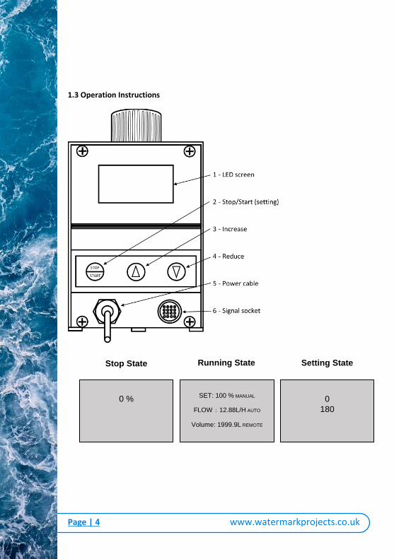
1.3 Operation Instructions
1. LED screen
2. Stop/Start (setting)
3.Increasing
4. Reducing
5. Power cable
6. Signal plug
Stop State: 0 %
Running State:
SET: 100 % MANUAL
FLOW:12.88L/H AUTO
Volume: 1999.9L REMOTE
Setting State: 180
0 %
Stop State
SET: 100 % MANUAL
FLOW:12.88L/H AUTO
Volume: 1999.9L REMOTE
0
180
Running State Setting State
Page | 5
www.watermarkprojects.co.uk
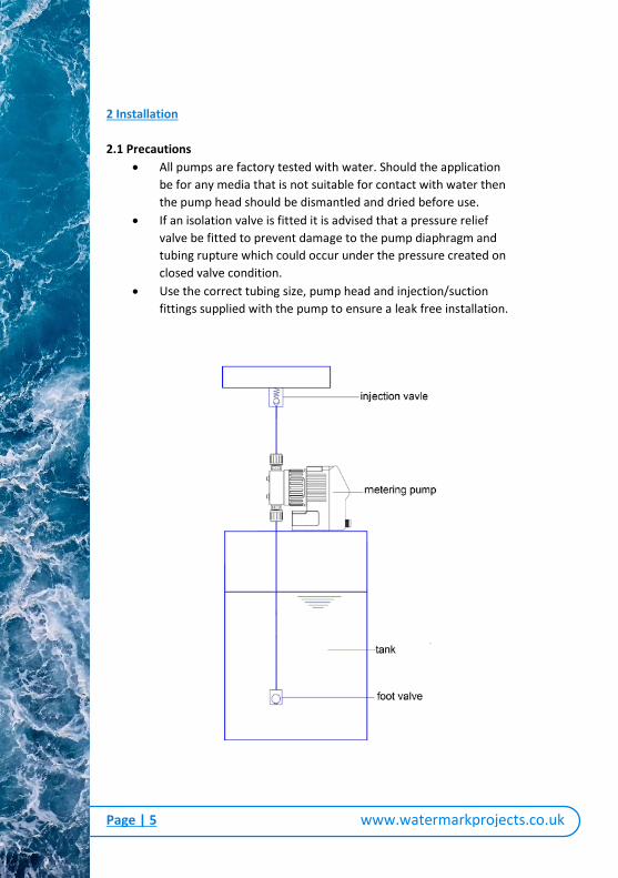
2 Installation
2.1 Precautions
All pumps are factory tested with water. Should the application
be for any media that is not suitable for contact with water then
the pump head should be dismantled and dried before use.
If an isolation valve is fitted it is advised that a pressure relief
valve be fitted to prevent damage to the pump diaphragm and
tubing rupture which could occur under the pressure created on
closed valve condition.
Use the correct tubing size, pump head and injection/suction
fittings supplied with the pump to ensure a leak free installation.
Page | 6
www.watermarkprojects.co.uk
2.2 Installation
Ensure Pump head fixing bolts are tightened.
The inlet and outlet ports of the pump must
be installed vertically.
The suction hose length should be kept to a
minimum allowing ease of pump priming.
The suction valve should also be fitted and
positioned just above the base of chemical
container to prevent clogging with solidified
sediment which may be present on the base.
The pump should be securely mounted.
Install the outlet tubes and injection valve,
this will greatly improve the accuracy of the
pump especially if dosing to an open
discharge.
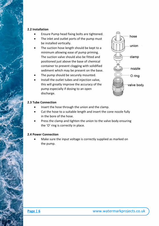
2.3 Tube Connection
Insert the hose through the union and the clamp.
Cut the hose to a suitable length and insert the cone nozzle fully
in the bore of the hose.
Press the clamp and tighten the union to the valve body ensuring
the ‘O’ ring is correctly in place.
2.4 Power Connection
Make sure the input voltage is correctly supplied as marked on
the pump.
Page | 7
www.watermarkprojects.co.uk
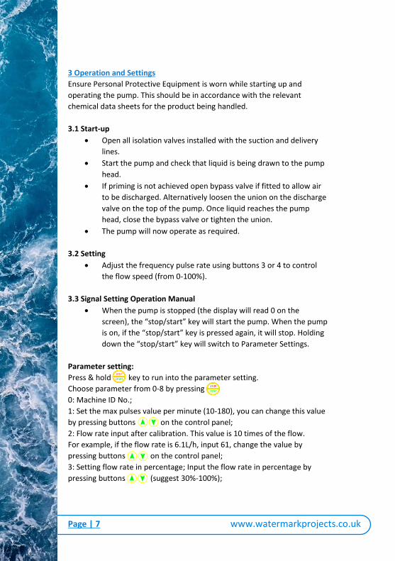
3 Operation and Settings
Ensure Personal Protective Equipment is worn while starting up and
operating the pump. This should be in accordance with the relevant
chemical data sheets for the product being handled.
3.1 Start-up
Open all isolation valves installed with the suction and delivery
lines.
Start the pump and check that liquid is being drawn to the pump
head.
If priming is not achieved open bypass valve if fitted to allow air
to be discharged. Alternatively loosen the union on the discharge
valve on the top of the pump. Once liquid reaches the pump
head, close the bypass valve or tighten the union.
The pump will now operate as required.
3.2 Setting
Adjust the frequency pulse rate using buttons 3 or 4 to control
the flow speed (from 0-100%).
3.3 Signal Setting Operation Manual
When the pump is stopped (the display will read 0 on the
screen), the “stop/start” key will start the pump. When the pump
is on, if the “stop/start” key is pressed again, it will stop. Holding
down the “stop/start” key will switch to Parameter Settings.
Parameter setting:
Press & hold key to run into the parameter setting.
Choose parameter from 0-8 by pressing
0: Machine ID No.;
1: Set the max pulses value per minute (10-180), you can change this value
by pressing buttons on the control panel;
2: Flow rate input after calibration. This value is 10 times of the flow.
For example, if the flow rate is 6.1L/h, input 61, change the value by
pressing buttons on the control panel;
3: Setting flow rate in percentage; Input the flow rate in percentage by
pressing buttons (suggest 30%-100%);

Page | 8
www.watermarkprojects.co.uk
4: RS485 communication interface: 0 for OFF, 1 for ON:
5: Function option: 0 for manual control; 1 for pulse signal function
multiply, 2 for pulse signal function divider, 3 for 4-20mA signal function, 4
and 5 not used;
6: Set the impulse count for multiplier or divider;
7: Remote control: 0 for OFF, 1 for ON;
8: Show 4-20mA input value
Wire connections:
1. for RS485 B terminal (blue)
2. for RS485 A terminal (yellow)
3. for ground line (black)
4. for impulse input (white)
5. for ground line (green)
6. for remote control (grey)
7. for 4-20mA input (red)
4. Maintenance and Repair
Warning
Electrical maintenance must be carried out by a qualified
electrician.
Before maintenance, unplug the power socket or fully isolate and
lock off the power.
Before maintenance, release any pressure from the dosing tubes,
and clean the pump head. Don’t use corrosive liquids.
If medium is a hazardous substance, please check the data sheets
of the medium. Discharge and wash the pump head before
maintenance.
4.1 Maintenance
Ensure following items are checked during maintenance;
Pump head bolts (make sure they have been firmly tightened)
Inlet and outlet tubes (make sure they have been firmly
connected)

Page | 9
www.watermarkprojects.co.uk
Pump head and valves (make sure they have been firmly
connected)
Check the leakage hole on the adapter base (the diaphragm may
be broken if there is visible leakage)
4.2 Diaphragm Replacement
Isolate pump from power supply, loosen the bolts ①;
Pull out the pump head ② and bolts ① from pump body;
Turn the diaphragm counter clockwise ③;
Unscrew from body ④;
Screw on a new diaphragm ③ clockwise and firmly tighten;
Ensure the pump body is replaced ④ with the drain hole
oriented in the downward position;
Remount the pump head. Ensure the inlet and outlet check
valves are in the correct orientation.
Warning
Leakage hole on the adapter base must be facing downward.
Recheck the screws on the pump head, tighten if necessary.

Page | 10
www.watermarkprojects.co.uk
5. Troubleshooting
Problem Possible Cause Solution
Power fa i lure Check the power supply
Fuse blowout Change fuse
Circuit i s interrupted Find the 'off' pos i tion
Incorrect wire selection
for parameter usedRe-check diagram
Pipe blockage Open va lve and clean
Not working Check the power supply
Supply tank is empty Fi l l supply tank
Pipe blockage Clean pipe
Closed va lve Open va lve
Air in the pipe Release a i r
Cavitations
Increase the pressure of the
suction and shorten the suction
pipe
Problem of priming Re-prime and check for leakage
Fi l ter blockageDisassemble fi l ter, clean or
replace
Stroke set to '0' Increase s troke s trength
Valve broken or di rty Clean or replace
Fi l ter blockageDisassemble fi l ter, clean or
replace
Cal ibration is wrong Evaluate and adjust accordingly
Medium viscos i ty i s too
high
Adjust temperature of product or
reduce viscos i ty. Al ternatively:
Increase pump and pipel ine s ize
Medium cavitationsIncrease suction pressure and
shorten suction pipe
Valve leakage Clean or replace va lve
Suction pipe leakageFind leakage pos i tion and
repair/replace
Fi l ter blockageDisassemble fi l ter, clean or
replace
Medium is changedCheck viscos i ty and other
parameters
Vent of supply tank is
blockedOpen vent
Pump does not
start
No Flow
Low Flow
Flow becomes
gradually lower
Page | 11
www.watermarkprojects.co.uk
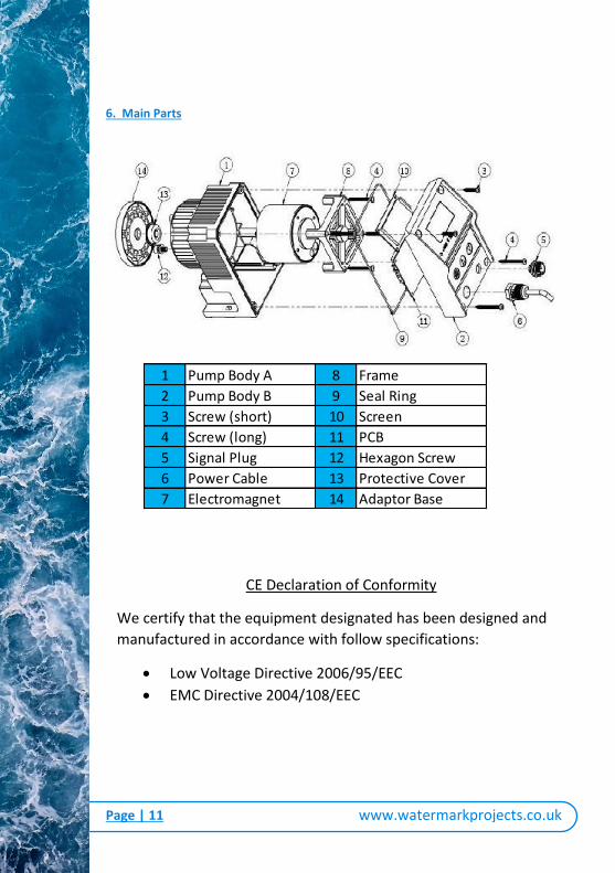
6. Main Parts
1 Pump Body A 8 Frame
2 Pump Body B 9 Seal Ring
3 Screw (short) 10 Screen
4 Screw (long) 11 PCB
5 Signal Plug 12 Hexagon Screw
6 Power Cable 13 Protective Cover
7 Electromagnet 14 Adaptor Base
CE Declaration of Conformity
We certify that the equipment designated has been designed and
manufactured in accordance with follow specifications:
Low Voltage Directive 2006/95/EEC
EMC Directive 2004/108/EEC

Page | 12
www.watermarkprojects.co.uk
Thank you for choosing Watermark Projects.
For further information on our other products you can visit our website-
www.watermarkprojects.co.uk
Or contact the Watermark Projects team-
01204 574 721