chemical engineering science 62 (2007) 1997 ... - mvt…¤ge/tomas_offprint_ces_7149.pdf · solid...
TRANSCRIPT

This article was originally published in a journal published byElsevier, and the attached copy is provided by Elsevier for the
author’s benefit and for the benefit of the author’s institution, fornon-commercial research and educational use including without
limitation use in instruction at your institution, sending it to specificcolleagues that you know, and providing a copy to your institution’s
administrator.
All other uses, reproduction and distribution, including withoutlimitation commercial reprints, selling or licensing copies or access,
or posting on open internet sites, your personal or institution’swebsite or repository, are prohibited. For exceptions, permission
may be sought for such use through Elsevier’s permissions site at:
http://www.elsevier.com/locate/permissionusematerial
Autho
r's
pers
onal
co
py
Chemical Engineering Science 62 (2007) 1997 – 2010www.elsevier.com/locate/ces
Adhesion of ultrafine particles—A micromechanical approach
Jürgen Tomas∗
Mechanical Process Engineering, The Otto-von-Guericke-University, Universitätsplatz 2, D – 39 106 Magdeburg, Germany
Received 9 August 2006; received in revised form 19 December 2006; accepted 21 December 2006Available online 13 January 2007
Abstract
In particle processing and product handling of fine (d < 100 �m), ultrafine (d < 10 �m) and nanosized particles (d < 0.1 �m), thewell-known flow problems of dry cohesive powders in process apparatuses or storage and transportation containers include bridging,channelling, widely spread residence time distribution associated with time consolidation or caking effects, chemical conversions anddeterioration of bioparticles. Avalanching effects and oscillating mass flow rates in conveyors lead to feeding and dosing problems.Finally, insufficient apparatus and system reliability of powder processing plants are also related to these flow problems. Thus, it is very essentialto understand the fundamentals of particle adhesion with respect to product quality assessment and process performance in particle technology.
The state-of-the-art in constitutive modelling of elastic, elastic–adhesion, elastic–dissipative, plastic–adhesion and plastic–dissipative contactdeformation response of a single isotropic contact of two smooth spheres is briefly discussed. Then the new models are shown that describethe elastic–plastic force–displacement and moment–angle behaviour of adhesive and frictional contacts.
Using the model “stiff particles with soft contacts”, a sphere–sphere interaction of van der Waals forces without any contact deformationdescribes the “stiff” attractive term. A plate–plate model is used to calculate the “soft” micro-contact flattening and adhesion. Various contactdeformation paths for loading, unloading and contact detachment are discussed. Thus, the varying adhesion forces between particles dependdirectly on this “frozen” irreversible deformation. Thus, the adhesion force is found to be load dependent. Their essential contribution on thetangential force in an elastic–plastic frictional contact with partially sticking within the contact plane and microslip, the rolling resistance andthe torque of mobilized frictional contact rotation is shown.� 2007 Elsevier Ltd. All rights reserved.
Keywords: Ultrafine particles; Particle processing; Adhesion forces; Granular materials; Contact mechanics
1. Introduction
In particle processing and product handling of fine(d < 100 �m), ultrafine (d < 10 �m) and nanosized particles(d < 0.1 �m), the well-known flow problems of dry cohesivepowders in process apparatuses or storage and transportationcontainers include bridging, channelling, widely spread res-idence time distribution associated with time consolidationor caking effects, chemical conversions and deterioration ofbioparticles. Avalanching effects and oscillating mass flowrates in conveyors lead to feeding and dosing problems. Fi-nally, insufficient apparatus and system reliability of powderprocessing plants are also related to these adhesion problems.
∗ Tel.: +49 391 67 18783; fax: +49 391 67 11160.E-mail address: [email protected].
0009-2509/$ - see front matter � 2007 Elsevier Ltd. All rights reserved.doi:10.1016/j.ces.2006.12.055
The challenge is to understand physically the fundamentals ofparticle adhesion with respect to product quality assessment,process performance and control in powder technology, i.e.,particle conversion, formulation and handling.
Therefore modelling the single particle adhesion and suit-able micro–macro interaction rules, constitutive equations haveto be derived to describe the mechanical behaviour of cohe-sive powders and to simulate the dynamics of packed particlebeds in powder processing (e.g. agglomeration, disintegration,comminution), powder storage and flow. Using this microme-chanical philosophy in powder mechanics, first physical modelswere derived and published by Molerus (1975, 1978) and latercontinued by Tomas in the theses (1983, 1991), supplementedand reviewed again (2004a,b).
Independently from this, the so-called discrete elementmethod (DEM) was developed in rock mechanics (Cundalland Strack, 1979). The rapid and collisional flow of

Autho
r's
pers
onal
co
py
1998 J. Tomas / Chemical Engineering Science 62 (2007) 1997 –2010
nonadhering particles was modelled, e.g. by Satake and Jenkins(1988) and Nedderman (1992). Tardos (1997) and Tardoset al. (2003) discussed the slow frictional and intermediate flowfor compressible powders without any cohesion from the fluidmechanics point of view. Recently, a lot of papers about theflow of granular materials were compiled by Hinrichsen andWolf (2004) and Garcia-Rojo et al. (2005).
2. State of arts
Particle adhesion is caused by surface and field forces (vander Waals, electrostatic and magnetic forces), material bridgesbetween particle surfaces (liquid and solid bridges, flocculants)and interlocking (e.g. Israelachvili, 1992; Rumpf, 1958, 1974,1991; Schubert, 1979, 2003; Tomas and Schubert, 1981; Tomas,1983, 1991, 1997), Fig. 1:
• Surface and field forces at direct contact:◦ Van der Waals forces (all dry powders consisting
of polar, induced polar and non-polar molecules,e.g. minerals, chemicals, plastics, pharmaceuticals,food).
◦ Electrostatic forces:– Electric conductor (metal powders).– Electric non-conductor (polymer powders, plas-
tics, detergents).◦ Magnetic force (iron powder).
• Material bridges between particle surfaces:◦ Hydrogen bonds of adsorbed surface layers of con-
densed water (powders).◦ Organic macromolecules as flocculants in suspen-
sions (in waste water).◦ Liquid bridges of
– low viscous wetting liquids by capillary pressureand surface tension (moist sand),
– high viscous bond agents (resins).◦ Solid bridges by
– re-crystallization of liquid bridges which containsolvents (salt),
– solidification of swelled ultrafine gel particles(starch, clay),
– freezing of liquid bridge bonds (frozen soil),– chemical reactions with adsorbed surface layers
(cement hydration by water) or cement with inter-stitial pore water (concrete),
– solidification of high viscous bond agents(asphalt),
– contact fusion by sintering (aggregates of nanopar-ticles, ceramics),
– chemical bonds by solid–solid reactions (glassbatch, mechanically activated metal alloys).
• Interlocking by macromolecular and particle shape effects:◦ interlocking of chain branches at macromolecules
(proteins),
◦ interlocking of contacts by overlaps of surfaceasperities (rough particles),
◦ interlocking by hook-like bonds (fibres).
It is worth to note here that van der Waals forces—the focus ofthis paper—act at the surfaces of dry ultrafine particles. Theyare dominant and approximately 104–106 times the gravita-tional force, see e.g. calculations of Rumpf (1974) and Schubert(1979).
The fundamentals of molecular attraction potentials and themechanics of adhesion are treated for example by Krupp (1967),Israelachvili and Tabor (1973), Tabor (1977), Israelachvili(1992), Maugis (1999) and Kendall (2001). Contact mechanicsand impact mechanics without load dependent adhesion aredescribed by Johnson (1985) and Stronge (2000). Recently,multiscale modelling in “nanomechanics”, i.e., the combina-tion of molecular dynamics (MD), thermodynamics and finiteelement methods (FEM) is described by Liu et al. (2006).
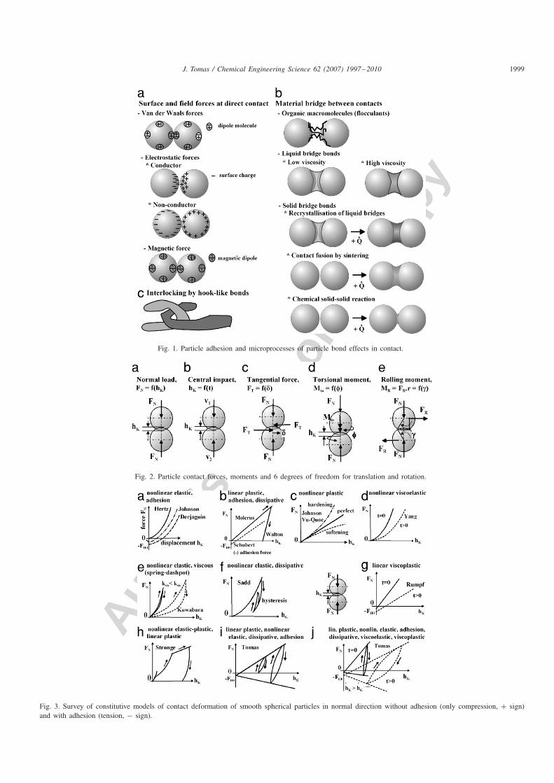
Six degrees of freedom have to be considered in sin-gle contact of smooth spheres: one normal load or centralimpact in direction of principal axis and one torsional mo-ment around this axis, two tangential forces and two rollingmoments within the plane of flattened contact and their re-spective constitutive force–displacement and moment—anglerelations, Fig. 2.
The basic models for elastic behaviour were derived byHertz (1882), Fig. 3(a), and for constant adhesion by Johnsonet al. (1971), Derjaguin et al. (1975), Thornton and Yin (1991),Fig. 3(a). Plastic behaviour was described by Stieß (1976),Walton and Braun (1986), Thornton (1997), Thornton and Ning(1998). But the increase of adhesion force due to plastic contactdeformation was introduced by Molerus (1975) and Schubertet al. (1976), Fig. 3(b). Non-linear plastic, displacement-driven contact hardening was investigated by Johnson (1985),Greenwood (1997), Vu-Quoc and Zhang (1999), Mesarovicand Johnson (2000), Quintanilla (2002) and Castellanos (2005),Fig. 3(c). Additionally, contact softening could be included(Thomas, 2004a,b), Fig. 3(c). Viscoelasticity and relaxationwas considered by Yang (1966), Fig. 3(d). Energy dissipationof the non-linear elastic contact with viscous spring–dashpotbehaviour was modelled by Kuwabara and Kono (1987), Tsujiet al. (1992) and Brilliantov et al. (1996), Fig. 3(e), and duringone unload/reload cycle by Sadd et al. (1993), Fig. 3(f). Dif-ferent elastic, elastic–plastic and fully plastic behaviour with-out any adhesion were recently described by Stronge (2000),Fig. 3(h). Time dependent viscoplasticity was modelled byRumpf et al. (1976) and Luding et al. (2005), Fig. 3(g). Usingideas of Krupp (1967), Rumpf et al. (1976), Schubert et al.(1976), Thornton and Ning (1998), the author (Tomas, 2000,2001a, 2003) had published a model for adhesive contact of ul-trafine particles with elastic–plastic and dissipative behaviour,Fig. 3(i) and (j), that is briefly explained in Section 3.1.
This inelastic contact flattening leads to an increase of ad-hesion force FH (FN) depending on the applied normal loadFN —the load or pre-consolidation history. This essential ef-fect of a soft particle contact was modelled by Krupp (1967),Dahneke (1972), Rumpf et al. (1976), Molerus (1975), Maugis
Autho
r's
pers
onal
co
py
J. Tomas / Chemical Engineering Science 62 (2007) 1997–2010 1999
Fig. 1. Particle adhesion and microprocesses of particle bond effects in contact.
Fig. 2. Particle contact forces, moments and 6 degrees of freedom for translation and rotation.
Fig. 3. Survey of constitutive models of contact deformation of smooth spherical particles in normal direction without adhesion (only compression, + sign)and with adhesion (tension, − sign).

Autho
r's
pers
onal
co
py
2000 J. Tomas / Chemical Engineering Science 62 (2007) 1997 –2010
Fig. 4. Survey of constitutive models of contact displacement of smoothspherical particles in tangential direction (− sign means reverse shear anddisplacement directions).
and Pollock (1984), Tomas (2001a) and Castellanos (2005) thatis shown in Section 3.2.
Besides the linear elastic tangential force–displacement re-lation, Hook’s law, Fig. 4 panel (a), Fromm (1927), Cattaneo(1938), Föppl (1947), Mindlin (1949), Sonntag (1950), Mindlinand Deresiewicz (1953) modelled the non-linear contact load-ing path up to Coulomb friction as the limit, Fig. 4 panel (b).The contribution of constant adhesion forces in Coulomb fric-tion was considered by Derjaguin et al. (1975) and Thornton(1991), Fig. 4 panel (b). Mindlin and Deresiewicz (1953),Walton and Braun (1986), Thornton (1991), Di Renzo andDi Maio (2003) modelled different non-linear paths for load,unload, reload, reverse shear load, unload and load, Fig. 4panel (c), but without any adhesion. Thus, this essential effectof history or load dependent adhesion FH (FN) in Coulombfriction of ultrafine particles is demonstrated in Fig. 4 panel(d) and explained in Section 3.3.
The sources of an additional rolling resistance FR should beconsidered by partially sticking and by micro-roughness of con-tact surfaces, and especially, by contact deformations (Fromm,1927; Sonntag, 1950; Johnson, 1985; Iwashita and Oda, 2000).Another effect is that the sphere can rotate (twist or spin) aroundits principal axis within the contact plane. The torque Mto asradial distribution versus radius coordinate of circular elasticcontact area as function of the rotation angle � without anyadhesion was calculated by Mindlin (1949), Cattaneo (1952),Deresiewicz (1954) and Johnson (1985). Their theories werethe basis to model the influence of load dependent adhesionwith respect to rolling and torsion moments of ultrafine par-ticles, see Sections 3.4 and 3.5. It is worth to note here thatnormal displacement, sliding, rolling and twisting are coupledin a single contact of the moving particle packing, e.g. Farkaset al. (2003) and Brendel et al. (2004). The essential particleproperties are described in Section 3.6. Finally, the sensitivityof load dependent adhesion FH (FN) on the friction limits ofsliding, rolling and torsion is compared in Section 3.7.
3. Constitutive models for elastic–plastic, dissipativebehaviour and load dependent adhesion
This paper is intended to focus on the model of isotropic,stiff, and linear elastic, spherical particles that are approachingto soft contacts by attractive adhesion forces of smooth surfaces.Thus, this soft or compliant contact displacement is assumedto be small hK/d>1 compared to the size (diameter) of thestiff particle. The particles may have a certain material stiffnessso that the volume deformation is negligible. During surfacestressing the stiff particle is not so much deformed that it under-goes a certain change of the particle shape. This is equivalent toa model of “healing contacts” after stressing and deformation.
3.1. Particle contact constitutive model for normal loading
A typical normal force–displacement diagram is demon-strated in Fig. 5. The zero-point of this diagram hK = 0is equivalent to the characteristic adhesion separation of adirect contact aF=0. After approaching FN ∝ a−2 (witha = aF=0 − hK) from an infinite distance −∞ to a minimumseparation a = aF=0, Fig. 5(a), the smooth sphere–spherecontact without any contact deformation is formed by theshort-range attractive adhesion force FN =−FH0 (the so-calledjump in),
FN = −FH0 = − CH,slsr1,2
6(aF=0 − hK)2= − FH0a
2F=0
(aF=0 − hK)2(1)
with the median particle radius r1,2 or characteristic radius ofcontact surface curvature (r1 and r2 are the principal radii ofsurface curvatures of both spheres before flattening),
r1,2 =(
1
r1+ 1
r2
)−1
. (2)
The Hamaker constant (Hamaker, 1937) CH,sls = (0.2.40)×10−20 J for solid–liquid–solid interaction (index sls) accord-ing to the continuum theory of Lifshitz (1955, 1956) is relatedto continuous media and depends on their permittivities (di-electric constants) and refractive indices, for details see Krupp(1967), Israelachvili and Tabor (1973) and Israelachvili (1992).The characteristic adhesion separation for the direct contact ofspheres is of a molecular scale (atomic centre-to-centre dis-tance) and can be estimated for the total force equilibriumF = −dU/da = 0 of molecular attraction and repulsion po-tentials a = aF=0. This separation of the interaction potentialminimum amounts to about aF=0 = 0.3–0.4 nm. With respectto large specific surfaces of ultrafine particles, this separationaF=0 depends on the properties of liquid-equivalent packedadsorbed water layers. Consequently, the particle contact be-haviour is influenced by more or less mobile adsorption lay-ers due to condensed humidity of ambient air (e.g. Chigazawaet al., 1981; Tomas, 1983; Schütz and Schubert, 1980; Restagnoet al., 2002; Schumann, 2005). The minimum centre separationaF=0 is assumed to be constant during particle contact loadingand unloading. This mechanical behaviour is equivalent to stiffsphere repulsion of molecules (Israelachvili, 1992).

Autho
r's
pers
onal
co
py
J. Tomas / Chemical Engineering Science 62 (2007) 1997–2010 2001
Fig. 5. Calculated normal force–displacement diagram of characteristic contact flattening of limestone particles, modelled as smooth mono-disperse spheres,median diameter d50 = 1.2 �m. For convenience, pressure and compression are defined as positive but tension and extension are negative. The smooth spheresapproach, Eq. (1), form an elastic contact, Eq. (3), start with yielding at point Y and form an elastic–plastic contact, line Y–U, Eq. (7), can be unloaded atpoint U, Eq. (12), achieve the adhesion limit at point A, Eq. (11), and finally, detach with increasing separation, Eq. (15). To avoid an overestimation, thecharacteristic adhesion force of rigid sphere–sphere contact FH0 = −2.64 nN was back-calculated from limestone powder shear tests (Tomas, 2004a). Thenecessary material data for this diagram are shown in Section 3.7.
Now, the contact may be loaded from point FH0 to Y and,as the response, is elastically deformed with an approximatedcircular contact area (Hertz, 1882), Fig. 5(b),
FN = 23E∗
√r1,2h
3K (3)
with the averaged material stiffness as series of elastic ele-ments 1 and 2 (which is equivalent to the sum of reciprocal ele-ment stiffness (compliances), E modulus of elasticity, � Poissonratio):
E∗ = 2
(1 − �2
1
E1+ 1 − �2
2
E2
)−1
. (4)
When this Hertz curve intersects the abscissa the total forceequilibrium FN = 0 is obtained within the self-equilibratingcontact. With increasing external normal load this soft contactstarts at a pressure pf with plastic yielding at the point Y,Fig. 5(c), (�A elastic–plastic contact area coefficient, �p plasticrepulsion coefficient):
hK,f,el.pl = r1,2
[3�pf (�A − �p)
2E∗
]2
. (5)
This yield point Y is located here below the abscissa, i.e., thecontact force equilibrium FN = 0 includes a certain elastic orelastic–plastic deformation as response of effective adhesionforce (1 + �)FH0 with � the elastic–plastic contact consoli-dation coefficient. The micro-yield surface is reached and thismaximum pressure pf cannot be exceeded and results in acombined elastic–plastic yield limit of the plate–plate contact
with an annular elastic zone and a circular centre. A confinedplastic field is formed inside of the contact circle.
Constant mechanical properties provided, the finer the par-ticles the smaller is the force necessary for yielding (Tomas,2000). An initial and exclusive elastic contact deformation atloading, see the position of yield point Y in Fig. 5 below theaxis, has no relevance for irreversible compression of fine toultrafine powders in the industrial practice of processing andhandling. Generally, averaged macroscopic normal stresses inapparatuses, containers, conveyors and reactors amount to about� ≈ F̄N/d2?1 kPa. Because of microscopic normal forces ofabout FN?1 nN between the particles, exclusive elastic con-tact deformations can be excluded here.
Besides a complex numerical model of Castellanos (2005),the linear elastic–plastic force–displacement models for load-ing introduced by Schubert et al. (1976) and by Thornton andNing (1998) were the basis to supplement their approaches byan extended attractive force contribution of contact flattening(Tomas, 2000, 2001a). The particle contact force equilibriumbetween attraction (−) and elastic plus, simultaneously, plasticrepulsion (+) is calculated by (r∗
K represents the coordinate ofannular elastic contact area, i.e., for rK,f �r∗
K �rK ):∑FN,i = 0 = − FH0 − pVdW�r2
K − FN + pf �r2K,f
+ 2�∫ rK
rK,f
pel(r∗K)r∗
K dr∗K . (6)
Superposition provided (Derjaguin et al., 1975), the adhesionforce FH0, Eq. (1), includes both the attraction at particleapproach, i.e., short-range sphere–sphere interaction, and the

Autho
r's
pers
onal
co
py
2002 J. Tomas / Chemical Engineering Science 62 (2007) 1997 –2010
contribution outside in the annular area that is located at theperimeter closed by the contact. The term with the van derWaals pressure −pVdW�r2
K models the effective attractionwithin the circular contact area between flattened smooth par-ticle surfaces. The distribution of surface asperities, their localflattening and penetration is neglected at this model.
Thus, the elastic–plastic yield limit for loading results in asimple function, line Y–U in Fig. 5:
FN = �r1,2pf (�A − �p)hK − FH0. (7)
The elastic–plastic contact area coefficient �A represents theratio of plastic particle contact deformation area Apl to totalcontact deformation area AK =Apl +Ael and includes a certainelastic displacement (Tomas, 2001a, 2003):
�A = 2
3+ 1
3
Apl
AK
. (8)
The solely elastic contact deformation Apl =0, �A= 23 , has only
minor relevance for cohesive powders in loading, but for thecomplete plastic contact deformation (Apl=AK) the coefficient�A = 1 is obtained.
The adhesion force per unit planar surface area or attrac-tive pressure pVdW which is used here to describe the vander Waals interactions at contact, is equivalent to a theoret-ical bond strength and can be simply calculated as (�sls ≈0.25–50 mJ/m2 surface tension solid–liquid–solid and conse-quently pVdW ≈ 3–600 MPa):
pVdW = CH,sls
6�a3F=0
= 4�sls
aF=0. (9)
The plastic repulsion coefficient �p describes a dimensionlessratio of attractive van der Waals pressure pVdW for a plate–platemodel, Eq. (9), to a constant repulsive micro-yield strength pf ,(i.e., particle micro-hardness):
�p = pVdW
pf
= CH,sls
6�a3F=0pf
= 4�sls
aF=0pf
. (10)
For a stiff contact this coefficient is infinitely small, i.e., �p ≈ 0and for a soft or compliant contact �p → 1. For the sake ofsimplicity the contact parameters �A and �p are set constant.This makes sense in the nanometre scale of contact radius forultrafine particles with sizes below 10 �m.
The elastic–plastic yield limit, Eq. (7), cannot be crossed.Between the elastic–plastic yield limit and the adhesion limit
FN(hK,A) = −�r1,2pVdWhK,A − FH0 (11)
the elastic domain is located. Any load FN yields an increasingdisplacement hK . But, if one would unload, beginning at ar-bitrary point U, the elastically deformed, annular contact zonerecovers along a parabolic curve U–A,
FN = 23E∗
√r1,2(hK − hK,A)3 − �r1,2�ppf hK,A − FH0.
(12)
At the intersection A between unload curve, Eq. (12), andadhesion limit, Eq. (11), the plate–plate contact remains just ad-
Fig. 6. Calculated normal force–displacement diagram of characteristiccontact deformation of cohesive limestone particles modelled as smoothmono-disperse spheres, median diameter d50 = 1.2 �m. The hysteresis be-haviour could be shifted along the elastic–plastic limit and depends on thepre-loading, or in other words, on pre-consolidation level. Thus, the vari-ation in adhesion forces between particles depends directly on this frozenirreversible deformation, the so-called contact pre-consolidation history.
hered with a “frozen” radius rK,A or plastic displacement hK,A
and zero unload stiffness (index (0) denotes the old value):
hK,A,(1) = hK,U − 3√
hK,f,el.pl(hK,U + �hK,A,(0))2. (13)
The reloading would run along an equivalent curve from pointA to point U forward to the displacement hK,U as well, Fig. 5:
FN = − 23E∗
√r1,2(hK,U − hK)3 + �r1,2pf (�A − �p)hK,U
− FH0. (14)
If the adhesion limit at point A in the diagram of Fig. 5 is reachedthen the contact plates detach with the increasing distance a =aF=0 + hK,A − hK (Tomas, 2003), see Fig. 5(d). This actualparticle separation a can be considered for the calculation bymeans of a long-range hyperbolic adhesion force curve FN,Z ∝pVdW(a) ∝ a−3 (e.g. Krupp, 1967; Israelachvili, 1992):
FN(hK) = − FH0a2F=0
(aF=0 − hK)2
− �r1,2pVdWhK,A
(aF=0 + hK,A − hK)3a3F=0. (15)
It is worth to note here that the secant unload stiffness betweenhK,A and hK,U (450–820 N/m) increases with increasing con-tact flattening hK,U , see the steeper unload curves in Fig. 6with increasing load FN,U . Thus, with increasing external loadapplied at any process, e.g. in powder compaction, the parti-cle contacts become stiffer and stiffer and approach the solidbehaviour of a compressed briquette or tablet.
These theoretical predictions of normal force–displacementbehaviour are very useful to describe the compressionof primary elastic, elastic–plastic particle compounds or

Autho
r's
pers
onal
co
py
J. Tomas / Chemical Engineering Science 62 (2007) 1997–2010 2003
elastic–plastic granules at conveying and handling operations.The elastic–plastic load and Hertzian unload curves and theunload/reload hysteresis were experimentally confirmed forcoarse granules (Antonyuk et al., 2005; Antonyuk, 2006).
3.2. Load dependent adhesion force
The slopes of elastic–plastic yield and adhesion limits inFig. 5 are characteristics of irreversible particle contact stiff-ness, softness or compliance.
Moreover, if one eliminates the centre approach hK of theloading and unloading functions, Eqs. (7) and (12), an impliednon-linear function for the contact pull-off force FN =−FH atthe detachment point A is obtained, see Tomas (2004a,b):
FH,(1) = FH0 + �(FN + FH0) − �r21,2�ppf
×[
3(FN + FH0)
2r21,2E
∗
(1 + FH,(0) − FH0
FN + FH0
)]2/3
. (16)
The index (0) denotes the old and (1) the new value of iterations.The unloading point U is stored in the memory of the contactas pre-consolidation history. This general non-linear adhesionforce model implies the dimensionless, elastic–plastic contactconsolidation coefficient �, the “stiff” contribution of adhesionforce FH0(r1,2) without any contact flattening and, additionally,the influence of adhesion, stiffness, averaged particle radius r1,2and the averaged modulus of elasticity E∗ in the last term ofthe equation. This positive non-linear adhesion–normal forcefunction FH = f (FN) can be linearized (Tomas, 2004a):
FH = �A
�A − �p
FH0 + �p
�A − �p
FN = (1 + �)FH0 + �FN .
(17)
Additionally, this Eq. (17) can be checked by combining the ad-hesion limit FH =−FN(hK,A), Eq. (15), with the elastic–plasticyield limit FN(hK,U ), Eq. (7), for the centre approach hK,A =hK,U . The dimensionless, so-called elastic–plastic contact con-solidation coefficient � determines the slope of adhesion forceFH influenced by predominant plastic contact failure:
� = �p
�A − �p
= pVdW
pf
12
3+ 1
3
Apl
AK
− pVdW
pf
. (18)
This displacement or flattening coefficient � characterizes theirreversible particle contact stiffness or softness as well. A shal-low slope implies low adhesion level FH ≈ FH0 because ofstiff particle contacts, but a large slope means soft contacts, orin other words, a cohesive powder flow behaviour in the con-tinuum or macroscale (Tomas, 2001b). This model considers,additionally, the flattening of soft particle contacts caused bythe adhesion force �FH0. Thus, the total adhesion force FH
consists of a stiff contribution FH0 and a soft, displacement in-fluenced term �(FH0 + FN). Thus, Eq. (17) can be interpretedas a general linear constitutive model, i.e., linear in forces, butnon-linear in material characteristics (Tomas, 2001a, 2004).
3.3. Elastic–plastic, frictional tangential force of loaddependent adhesive contact
The tangential stiffness within the contact plane forelastic–frictional behaviour can be derived according to thetheory of Mindlin (1949) as function of tangential displace-ment � without any adhesion force. Mindlin’s model is sup-plemented for the elastic–plastic contact flattening caused by asufficiently large normal force FN and, consequently, partiallysticking by load dependent adhesion force FH (FN), Eq. (17),(the index H is used here for the adhesive contact of ultrafineparticles 1 and 2):
kT,H = dFT
d�= 4G∗rK
(1 − �
�C,H
)1/2
. (19)
Gi =Ei/2(1 + �i ), i = 1, 2 is the shear modulus and the aver-aged shear modulus G∗ is written as sum of reciprocal elementstiffness (see Eq. (4) for E∗ as well):
G∗ = 2
(2 − �1
G1+ 2 − �2
G2
)−1
. (20)
The initial stiffness kT,H0 is found at tangential displacement� = 0:
kT,H0 = dFT
d�
∣∣∣∣�=0
= 4G∗rK = 4G∗√r1,2hK . (21)
Thus, the tangential force–displacement relation within the con-tact plane can be expressed by a linear elastic contribution forthe no-slip region within the contact area according to Hook’slaw, Fig. 4 panel (a):
FT = 4G∗rK�. (22)
It is worth to note here that the contact radius rK depends onthe applied normal force FN of the elastic–plastic yield limit,Eq. (7):
r2K = FN + FH0
�pf (�A − �p). (23)
The tangential force–displacement relation FT (�) can be ex-pressed by a linear elastic contribution for the no-slip regionwithin the contact plane according to Hook’s law. FT and theinitial tangential stiffness kT,H0(FN), Eq. (21), increase withincreasing contact flattening FH (FN), see Fig. 7:
FT = 4G∗rK� = 4G∗√
(1 + �)(FH0 + FN)
��Apf
�. (24)
The Coulomb friction limit of the tangential force is describedby the coefficient of internal friction �i . It depends on theelastic–plastic contact consolidation, i.e., elastic–plastic flatten-ing by the normal force FN and the variable adhesion forceFH (FN) as well, Eq. (17):
FT,C,H = �i[FN + FH (FN)] = �i (1 + �)(FH0 + FN). (25)
The contact loses its elastic tangential stiffness at kT,H =0 andcompletely mobilized contact sliding is obtained for the friction
Autho
r's
pers
onal
co
py
2004 J. Tomas / Chemical Engineering Science 62 (2007) 1997 –2010
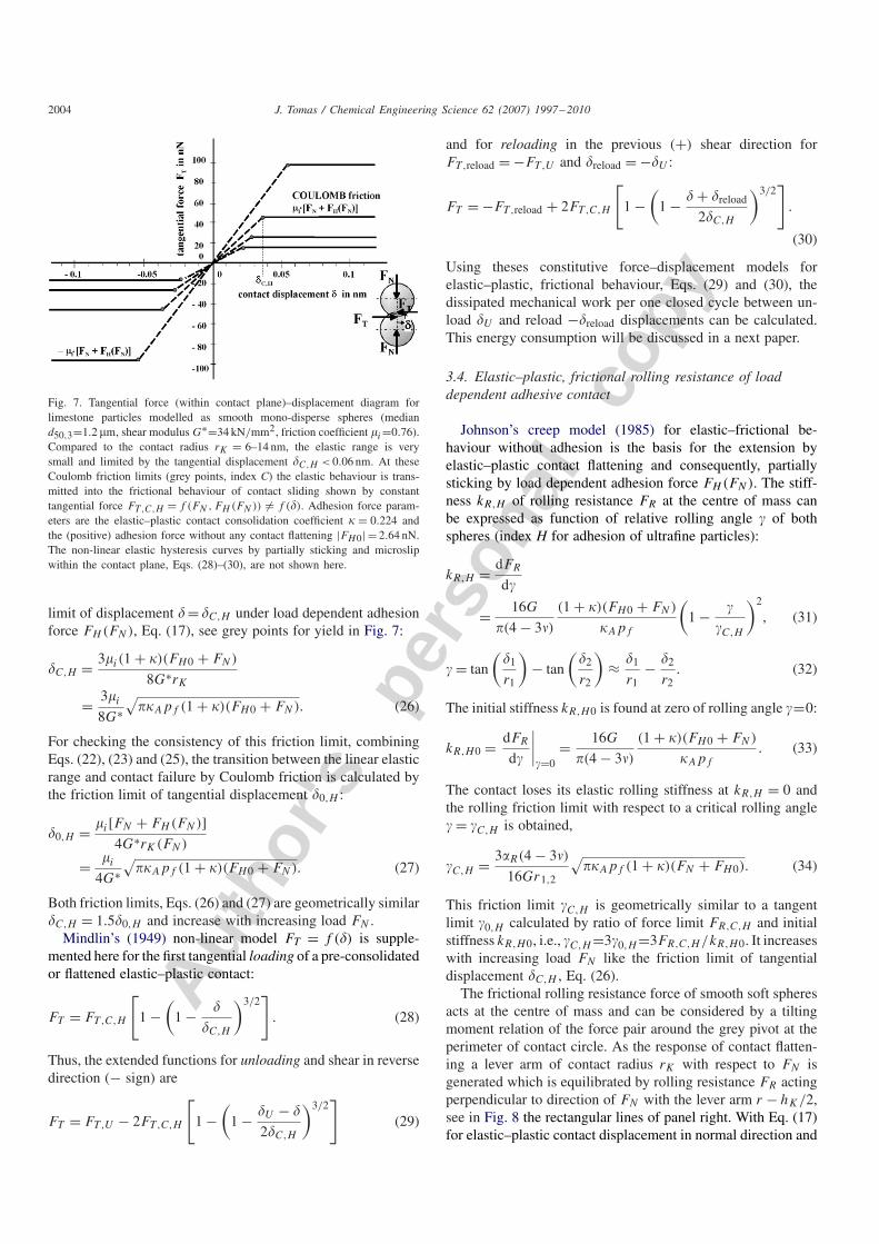
Fig. 7. Tangential force (within contact plane)–displacement diagram forlimestone particles modelled as smooth mono-disperse spheres (mediand50,3=1.2 �m, shear modulus G∗=34 kN/mm2, friction coefficient �i=0.76).Compared to the contact radius rK = 6–14 nm, the elastic range is verysmall and limited by the tangential displacement �C,H < 0.06 nm. At theseCoulomb friction limits (grey points, index C) the elastic behaviour is trans-mitted into the frictional behaviour of contact sliding shown by constanttangential force FT,C,H = f (FN , FH (FN )) �= f (�). Adhesion force param-eters are the elastic–plastic contact consolidation coefficient � = 0.224 andthe (positive) adhesion force without any contact flattening |FH0| = 2.64 nN.The non-linear elastic hysteresis curves by partially sticking and microslipwithin the contact plane, Eqs. (28)–(30), are not shown here.
limit of displacement �= �C,H under load dependent adhesionforce FH (FN), Eq. (17), see grey points for yield in Fig. 7:
�C,H = 3�i (1 + �)(FH0 + FN)
8G∗rK= 3�i
8G∗√
��Apf (1 + �)(FH0 + FN). (26)
For checking the consistency of this friction limit, combiningEqs. (22), (23) and (25), the transition between the linear elasticrange and contact failure by Coulomb friction is calculated bythe friction limit of tangential displacement �0,H :
�0,H = �i[FN + FH (FN)]4G∗rK(FN)
= �i
4G∗√
��Apf (1 + �)(FH0 + FN). (27)
Both friction limits, Eqs. (26) and (27) are geometrically similar�C,H = 1.5�0,H and increase with increasing load FN .
Mindlin’s (1949) non-linear model FT = f (�) is supple-mented here for the first tangential loading of a pre-consolidatedor flattened elastic–plastic contact:
FT = FT,C,H
[1 −
(1 − �
�C,H
)3/2]
. (28)
Thus, the extended functions for unloading and shear in reversedirection (− sign) are
FT = FT,U − 2FT,C,H
[1 −
(1 − �U − �
2�C,H
)3/2]
(29)
and for reloading in the previous (+) shear direction forFT,reload = −FT,U and �reload = −�U :
FT = −FT,reload + 2FT,C,H
[1 −
(1 − � + �reload
2�C,H
)3/2]
.
(30)
Using theses constitutive force–displacement models forelastic–plastic, frictional behaviour, Eqs. (29) and (30), thedissipated mechanical work per one closed cycle between un-load �U and reload −�reload displacements can be calculated.This energy consumption will be discussed in a next paper.
3.4. Elastic–plastic, frictional rolling resistance of loaddependent adhesive contact
Johnson’s creep model (1985) for elastic–frictional be-haviour without adhesion is the basis for the extension byelastic–plastic contact flattening and consequently, partiallysticking by load dependent adhesion force FH (FN). The stiff-ness kR,H of rolling resistance FR at the centre of mass canbe expressed as function of relative rolling angle of bothspheres (index H for adhesion of ultrafine particles):
kR,H = dFR
d
= 16G
�(4 − 3�)
(1 + �)(FH0 + FN)
�Apf
(1 −
C,H
)2
, (31)
= tan
(�1
r1
)− tan
(�2
r2
)≈ �1
r1− �2
r2. (32)
The initial stiffness kR,H0 is found at zero of rolling angle =0:
kR,H0 = dFR
d
∣∣∣∣=0
= 16G
�(4 − 3�)
(1 + �)(FH0 + FN)
�Apf
. (33)
The contact loses its elastic rolling stiffness at kR,H = 0 andthe rolling friction limit with respect to a critical rolling angle = C,H is obtained,
C,H = 3R(4 − 3�)
16Gr1,2
√��Apf (1 + �)(FN + FH0). (34)
This friction limit C,H is geometrically similar to a tangentlimit 0,H calculated by ratio of force limit FR,C,H and initialstiffness kR,H0, i.e., C,H =30,H =3FR,C,H /kR,H0. It increaseswith increasing load FN like the friction limit of tangentialdisplacement �C,H , Eq. (26).
The frictional rolling resistance force of smooth soft spheresacts at the centre of mass and can be considered by a tiltingmoment relation of the force pair around the grey pivot at theperimeter of contact circle. As the response of contact flatten-ing a lever arm of contact radius rK with respect to FN isgenerated which is equilibrated by rolling resistance FR actingperpendicular to direction of FN with the lever arm r − hK/2,see in Fig. 8 the rectangular lines of panel right. With Eq. (17)for elastic–plastic contact displacement in normal direction and

Autho
r's
pers
onal
co
py
J. Tomas / Chemical Engineering Science 62 (2007) 1997–2010 2005
Fig. 8. Rolling resistance force (at the centre of mass)–rolling angle dia-gram for limestone particles modelled as smooth mono-disperse spheres. Theso-called rolling friction coefficient is load dependent �R(FN ) = rK(FN )/r
and amounts here to �R ≈ 0.01 − 0.024. The linear elastic range is verysmall restricted by the limit of rolling angle C,H =8×10⁻⁵–1.9×10⁻⁴. Atthese limits the elastic behaviour is transmitted into the contact rolling shownby constant rolling resistance force FR,C,H �= f (), Eq. (36). FR,C,H andC,H depend on adhesion force FH (FN ). The hysteresis by partially stick-ing and microslip within the contact plane, Eqs. (38)–(40), is demonstratedhere only for the largest normal force.
load dependent adhesion force FH (FN), the critical rolling re-sistance FR,C,H results in
FR,C,H = rK
r[FN + FH (FN)] = rK
r(1 + �)(FH0 + FN).
(35)
Substitution of the contact radius rK of the elastic–plasticyield limit, Eq. (23), results nearly in a proportionality asFR,C,H (FN) ∝ F
3/2N :
FR,C,H = �R(1 + �)(FH0 + FN)
=√√√√ (1 + �)3(FH0 + FN)3
�r21,2pf �A
. (36)
With the moment (torque) MR =FRr of a sphere with radius rthe friction limit of the rolling moment follows from Eq. (36):
MR,C,H =√
(1 + �)3(FH0 + FN)3
�pf �A
. (37)
By integration of Eq. (31) the force–rolling angle function forthe first loading of the flattened elastic–plastic contact is ob-tained,
FR = FR,C,H
[1 −
(1 −
C,H
)3]
. (38)
Similarly to the constitutive tangential force–displacementmodel, Eqs. (29) and (30), the function for unloading androlling in reverse direction (− sign) is obtained as
FR = FR,U − 2FR,C,H
[1 −
(1 − U −
2C,H
)3]
(39)
and for reloading in the previous (+) rolling direction, i.e.,FR,reload = −FR,U and reload = −U :
FR = −FR,reload + 2FR,C,H
[1 −
(1 − reload +
2C,H
)3]
.
(40)
These force–displacement models FR() models are shownin Fig. 8. Equivalent to the resistance forces the rollingmoment–angle relations MR() = FR()r for loading, unload-ing and reloading result in
MR = MR,C,H
[1 −
(1 −
C,H
)3]
, (41)
MR = MR,U − 2MR,C,H
[1 −
(1 − U −
2C,H
)3]
, (42)
MR = −MR,reload + 2MR,C,H
[1−(
1−reload+
2C,H
)3]
. (43)
These rolling moment–rolling angle relations MR() were de-rived to calculate the dissipated mechanical work per one closedcycle between unload U and reload −reload angles.
3.5. Elastic–plastic, frictional twisting of load dependentadhesive contact
The torsional stiffness for elastic–frictional behaviour with-out any adhesion force can be derived according to Deresiewicz(1954) as function of torsional moment Mto. But the torsionalstiffness kto,H for elastic–plastic contact flattening and conse-quently, partially sticking by load dependent adhesion forceFH (FN), Eq. (17), amounts to (index H for adhesion of ultra-fine particles):
kto,H = dMto
d�= 8Gr3
K
3
[2
(1 − Mto
Mto,C,H
)−1/2
− 1
]−1
. (44)
The initial stiffness kto,H0 is found at vanishing torsional mo-ment Mto = 0 with Eq. (23) for the contact radius rK :
kto,H0 = dMto
d�
∣∣∣∣Mto=0
= 8G
3
[(1 + �)(FH0 + FN)
��Apf
]3/2
. (45)
This initial stiffness kto,H0, Eq. (45), increases with the loaddependent adhesion force FH (FN) and differs from the ini-tial torsional stiffness according to Mindlin (1949). For thelimestone powder (d50 = 1.2 �m) it gives very small valueskto,H0 = (35.500) × 10−15 Nm. For simplicity, the elasticmoment–rotation angle function can be approached as linearrelation, Fig. 9.
The contact loses its elastic torsional stiffness at kto,H = 0and completely mobilized “frictional” contact rotation is ob-tained for the friction limit of moment Mto = Mto,C,H under
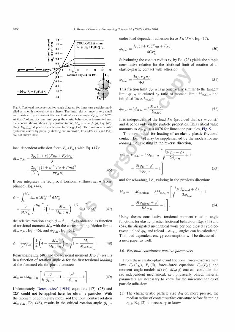
Autho
r's
pers
onal
co
py
2006 J. Tomas / Chemical Engineering Science 62 (2007) 1997 –2010
Fig. 9. Torsional moment–rotation angle diagram for limestone particles mod-elled as smooth mono-disperse spheres. The linear elastic range is very smalland restricted by a constant friction limit of rotation angle �C,H = 0.0076.At this Coulomb friction limit �C,H the elastic behaviour is transmitted intothe contact sliding shown by constant torque Mto,C,H �= f (�), Eq. (46).Only Mto,C,H depends on adhesion force FH (FN ). The non-linear elastichysteresis curves by partially sticking and microslip, Eqs. (49), (53) and (54),are not shown here.
load dependent adhesion force FH (FN) with Eq. (17):
Mto,C,H = 2�i (1 + �)(FH0 + FN)rK
3
= 2�i
3
√(1 + �)3(FN + FH0)
3
��Apf
. (46)
If one integrates the reciprocal torsional stiffness kto,H (com-pliance), Eq. (44),
� =∫ Mto
0kto,H (M∗
to)−1 dM∗
to
= 3
8Gr3K
∫ Mto
0
[2
(1 − Mto
Mto,C,H
)−1/2
− 1
]dM∗
to (47)
the relative rotation angle � = �1 − �2 is obtained as functionof torsional moment Mto with the corresponding friction limitsMto,C,H , Eq. (46), and �C,H , Eq. (51):
� = 4
3�C,H
[1
4
(4 − Mto
Mto,C,H
)−√
1 − Mto
Mto,C,H
]. (48)
Rearranging Eq. (48) and the torsional moment Mto(�) resultsin a function of rotation angle � for the first torsional loadingof the flattened elastic–plastic contact:
Mto = 4Mto,C,H
[√3�
�C,H
+ 1 − 3�
4�C,H
− 1
]. (49)
Unfortunately, Deresiewicz’ (1954) equations (17), (23) and(25) could not be applied here for ultrafine particles. Withthe moment of completely mobilized frictional contact rotationMto,C,H , Eq. (46), results in the critical rotation angle �C,H
under load dependent adhesion force FH (FN), Eq. (17):
�C,H = 3�i (1 + �)(FH0 + FN)
4Gr2K
. (50)
Substituting the contact radius rK by Eq. (23) yields the simpleconstitutive relation for the frictional limit of rotation of anelastic–plastic contact with adhesion:
�C,H = 3��i�Apf
4G. (51)
This friction limit �C,H is geometrically similar to the tangentlimit �0,H calculated by ratio of moment limit Mto,C,H andinitial stiffness kto,H0:
�C,H = 3�0,H = 3Mto,C,H
kto,H0. (52)
It is independent of the load FN (provided that �A = const.)and depends only on the particle properties. This critical valueamounts to �C,H ≈ 0.0076 for limestone particles, Fig. 9.
This new model for loading of an elastic–plastic frictionalcontact, Eq. (49) may be supplemented by the models for un-loading, i.e., twisting in the reverse direction,
Mto = Mto,U − 8Mto,C,H
[√3(�U − �)
2�C,H
+ 1
− 3(�U − �)
8�C,H
− 1
](53)
and for reloading, i.e., twisting in the previous direction:
Mto = − Mto,reload + 8Mto,C,H
[√3(�reload + �)
2�C,H
+ 1
− 3(�reload + �)
8�C,H
− 1
]. (54)
Using theses constitutive torsional moment–rotation anglefunctions for elastic–plastic, frictional behaviour, Eqs. (53) and(54), the dissipated mechanical work per one closed cycle be-tween unload �U and reload −�reload angles can be calculated.This load dependent energy consumption will be discussed ina next paper as well.
3.6. Essential constitutive particle parameters
From these elastic–plastic and frictional force–displacementlaws FN(hK), FT (�), force–force equations FH (FN) andmoment–angle models MR(), Mto(�) one can conclude thatsix independent mechanical, i.e., physically based, materialparameters are necessary to know for the micromechanics ofparticle adhesion:
(1) The characteristic particle size d50 or, more precise, themedian radius of contact surface curvature before flatteningr1,2, Eq. (2), is necessary to know.
Autho
r's
pers
onal
co
py
J. Tomas / Chemical Engineering Science 62 (2007) 1997–2010 2007
(2) The Hamaker constant CH,sls is the characteristic mate-rial parameter of the van der Waals adhesion betweenpractically dry particles for both types of bonds thesphere–sphere interaction of contact points FH0 and theplate–plate interaction of flattened contact by an externalnormal load FN (macroscopic normal stress �) and theinternal adhesion effect FH (FN). From this value theattractive van der Waals pressure pVdW and the surfacetension �sls, Eq. (9), can be obtained.
(3) The plastic micro-yield strength pf characterizes the plas-tic repulsion behaviour of the sphere contact. The ratioof the attractive van der Waals force per unit planar sur-face pVdW and this repulsive plastic micro-yield strengthpf results in the dimensionless plastic contact repulsioncoefficient �p, Eq. (10), and from that the elastic–plasticcontact consolidation coefficient � is obtained.
(4) The elastic contact repulsion is determined by the modulusof elasticity E and
(5) by the Poisson ratio �. From these material data the shearmodulus G is calculated.
(6) The frictional contact failure, i.e., the loss of elastic tan-gential or torsional stiffness, is characterized by the coef-ficient of internal friction �i between the adhesive particlesurfaces.
This information is essential to model the plastic yield limitsof cohesive powders when the stresses are approaching themaximum shear stress—the Coulomb–Mohr yield conditionsfor incipient and steady-state flow and consolidation.
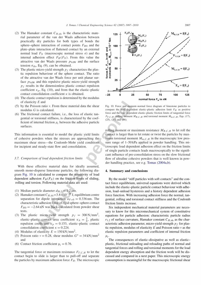
3.7. Comparison of load dependent friction limits
With these effective material data for ideally assumed,smooth mono-disperse limestone particles, the following dia-gram Fig. 10 is calculated to compare the sensitivity of loaddependent adhesion FH (FN) on the friction limits of sliding,rolling and torsion. Following material data are used:
(1) Median particle diameter d50,3 = 1.2 �m.(2) Hamaker constant CH,sls=3.8×10⁻²⁰ J, equilibrium centre
separation for dipole interaction aF=0 = 0.336 nm. Thecharacteristic adhesion force of rigid sphere–sphere contactFH0 = −2.64 nN was back-calculated from powder sheartests.
(3) The plastic micro-yield strength pf = 300 N/mm2,elastic–plastic contact area coefficient �A = 5
6 , plasticrepulsion coefficient �p = 0.153, elastic–plastic contactconsolidation coefficient � = 0.224.
(4) Modulus of elasticity E = 150 kN/mm2.(5) Poisson ratio � = 0.28, shear modulus G∗ = 34 kN/mm2
and(6) Contact friction coefficient �i = 0.76.
The tangential force or maximum resistance FT,C,H to let thecontact begin to slide is larger than to pull-off and separatethe particles by maximum adhesion force FH . The microscopic
Fig. 10. Force and moment–normal force diagram of limestone particles tocompare the load dependent elastic–plastic adhesion limit FH as positiveforce and the load dependent elastic–plastic friction limits of tangential forceFT,C,H , rolling moment MR,C,H and torsional moment Mto,C,H , Eqs. (17),(25), (37) and (46).
rolling moment or maximum resistance MR,C,H to let roll thecontact is larger than to let rotate or twist the particles by max-imum torsional moment Mto,C,H in the macroscopic low pres-sure range of 1–50 kPa applied in powder handling. This mi-croscopic load dependent adhesion effect on the friction limitsof single particle contacts leads macroscopically to the signifi-cant influence of pre-consolidation stress on the slow frictionalflow of ultrafine cohesive powders that is well known in pow-der handling practice, see e.g. Tomas (2004a,b).
4. Summary and conclusions
By the model “stiff particles with soft contacts” and the con-tact force equilibrium, universal equations were derived whichinclude the elastic–plastic particle contact behaviour with adhe-sion, load–unload hysteresis and a history dependent adhesionforce function. With increasing adhesion force the normal, tan-gential, rolling and torsional contact stiffness and the Coulombfriction limits increase.
Six independent mechanical material parameters are neces-sary to know for this micromechanical system of constitutiveequations for particle adhesion: characteristic particle radiusr1,2 of surface curvature, Hamaker constant CH,sls as the char-acteristic adhesion parameter, micro-yield strength pf for plas-tic repulsion, modulus of elasticity E and Poisson ratio � as theelastic repulsion parameters and coefficient of internal friction�i .
The consequences of elastic–dissipative as well as elastic–plastic, frictional unloading and reloading paths of normal andtangential forces and rolling and torsional moments for the loaddependent energy absorption and the friction work will be dis-cussed and compared in a next paper. This microscopic energyconsumption is meaningful for the macroscopic frictional shear
Autho
r's
pers
onal
co
py
2008 J. Tomas / Chemical Engineering Science 62 (2007) 1997 –2010
flow of cohesive ultrafine particulate solids and the agglomer-ate disintegration in powder processing and handling.
The microscopic load dependent adhesion effect on the fric-tion limits of single particle contacts leads macroscopically tothe significant influence of pre-consolidation stress on the fric-tional flow of ultrafine cohesive powders that is well known inpowder handling practice.
Thus, the physical models derived here are used for the ad-vanced data evaluation of various powder product propertiesconcerning particle size distribution (nanoparticles to granules),moisture content (dry, moist and wet) and material properties(minerals, chemicals, pigments, waste, plastics, food, etc.). Forexample, this approach was applied to evaluate the data dur-ing compression and impact tests of granules (Antonyuk et al.,2005, 2006). The models shown here are very meaningful todescribe the frictional shear flow of cohesive ultrafine powders.For this purpose, all the normal and tangential forces as wellas angular and trajectorial moments of particles have to be bal-anced to simulate their dynamics with physically realistic ma-terial data by the DEM (Tykhoniuk et al., 2007).
By modelling the single particle adhesion and by suitablemicro–macro interaction rules, constitutive equations will bederived to describe the pre-consolidation dependent, mechani-cal behaviour of ultrafine cohesive powders and to simulate thedynamics of packed particle beds in powder processing, i.e.,at agglomeration, disintegration, size reduction, powder stor-age and flow. At present, with this advanced knowledge animproved apparatus design (process chambers, feed hoppers,silos and conveyors) is accomplished for industrial partnersin process industries.
Notation
a contact separation, nmaF=0 minimum centre separation for force equilibrium
of molecular attraction and repulsion potentials,nm
AS,m mass related surface area, m2/gCH,sls Hamaker constant according to Lifshitz theory for
solid–liquid–solid interaction with liquid-like ad-sorption layers, J
d particle size, �md50,3 median particle diameter, mass basis, �mE modulus of elasticity, kN/mm2
F force, NFH adhesion force of single contact, nNFH0 adhesion force of a rigid contact without any con-
tact deformation, nNFN normal force of single contact, nNFT tangential force of single contact, nNG shear modulus, kN/mm2
hK height of overlap, indentation or centre approachof two spheres, nm
kN contact stiffness in normal direction, N/mkR contact stiffness of rolling resistance, �Nkto torsional contact stiffness, 10−15 Nm
kT contact stiffness in tangential direction, N/mM moment (torque), NmMR rolling moment, 10−17 NmMto torsional moment (torque), 10−17 Nmpf plastic micro-yield strength of particle contact,
MPapVdW attractive van der Waals pressure, see Eq. (9), MPar particle radius, �mrK contact radius, nm
Greek letters
rolling angle, distortion, dimensionless� tangential contact displacement, nm� elastic–plastic contact consolidation coefficient,
dimensionless�A elastic–plastic contact area coefficient, dimension-
less�p plastic repulsion coefficient, dimensionless�i coefficient of internal particle–particle friction,
i.e., Coulomb friction, dimensionless� Poisson ratio, dimensionless�sls surface tension solid–liquid–solid, mJ/m2
� rotation angle, dimensionless
Indices
A detachmentC Coulomb frictionel elasticH adhesionK particle contactl liquidm mass relatedN normalp pressure relatedpl plasticreload reloadR rollings solidto torsionalT tangentialU unloadVdW van der Waals0 initial, zero point(0) old value of iterations1,2 particle 1, particle 23 mass basis of cumulative distribution of particle
size (d3)
50 median particle size, i.e., 50% of cumulative dis-tribution
Acknowledgements
The author would like to thank H. Altenbach, A. Bertam,U. Gabbert, K. Kassner, D. Regener, P. Streitenberger, L.Tobiska, G. Warnecke, M. Zehn from Mechanics, Physics,
Autho
r's
pers
onal
co
py
J. Tomas / Chemical Engineering Science 62 (2007) 1997–2010 2009
Material Sciences, Mathematics and Process Engineering forthe fruitful collaboration within the DFG graduate school 828“Micro–Macro Interactions in Structured Media and ParticleSystems”.
The advices from H.-J. Butt, M. Kappl and S. Luding withrespect to the fundamentals of particle and powder mechan-ics were especially appreciated during the collaboration ofthe project “shear dynamics of cohesive, fine-disperse particlesystems” of the joint research program “Behaviour of GranularMedia” of German Research Association (DFG).
References
Antonyuk, S., 2006. Deformations- und Bruchverhalten von kugelförmigenGranulaten bei Druck- und Stoßbeanspruchung. Ph.D. Thesis, Docupoint,Magdeburg.
Antonyuk, S., Tomas, J., Heinrich, S., Mörl, L., 2005. Breakage behaviour ofspherical granulates by compression. Chemical Engineering Science 60,4031–4044.
Antonyuk, S., Tomas, J., Heinrich, S., Mörl, L., 2006. Impact breakage ofspherical granules: experimental study and DEM simulation. ChemicalEngineering and Processing 45, 838–856.
Brendel, L., Unger, T., Wolf, D.E., 2004. Contact dynamics for beginners.In: Hinrichsen, H., Wolf, D.E. (Eds.), The Physics of Granular Media.Wiley-VCH, Berlin, pp. 325–343.
Brilliantov, N.V., Spahn, V., Hertzsch, J.M., Pöschel, T., 1996. Model forcollisions in granular gases. Physical Review E 53, 5382–5392.
Castellanos, A., 2005. The relationship between attractive interparticle forcesand bulk behavior in dry and uncharged fine powders. Advances in Physics54, 263–376.
Cattaneo, C., 1938. Meccanica—Sul contatto di due corpi elastici,distribuzione locale degli sforsi. Academia Nationale dei Lincei, Rendiconti27, 342–348, 434–436, 474–478.
Cattaneo, C., 1952. Sulla torsione die due sfere elastiche a contatto. Annalidella Scuola Normale Superiore di Pisa (Seria III) 6, 1–16 In: Deresiewicz,H. (Ed.), 1954. Contact of elastic spheres under an oscillating torsionalcouple. Transactions of American Society Mechanical Engineers, Journalof Applied Mechanics 21, 52–56.
Chigazawa, M., Yamaguchi, T., Kanazava, T., 1981. Adhesion mechanism ofpowder particles due to vapour adsorption. In: Proceedings of InternationalSymposium on Powder Technology, Kyoto, pp. 202-207.
Cundall, P.A., Strack, O.D.L., 1979. A discrete numerical model for granularassemblies. Geotechnique 29, 47–65.
Dahneke, B., 1972. The influence of flattening on the adhesion of particles.Journal of Colloid and Interface Science 40, 1–13.
Deresiewicz, H., 1954. Contact of elastic spheres under an oscillating torsionalcouple. Transactions of American Society Mechanical Engineers, Journalof Applied Mechanics 21, 52–56.
Derjaguin, B.V., Muller, V.M., Toporov, Y.P., 1975. Effect of contactdeformations on the adhesion of particles. Journal of Colloid and InterfaceScience 53, 314–326.
Di Renzo, A., Di Maio, F.P., 2003. Comparison of contact-force models forthe simulation of collisions in DEM-based granular flow codes. ChemicalEngineering Science 59, 525–541.
Farkas, Z., Bartels, G., Unger, T., Wolf, D.E., 2003. Frictional couplingbetween sliding and spinning motion. Physical Review Letter 90,248302–248304.
Föppl, L., 1947. Die strenge Lösung für die rollende Reibung. Leibnitz Verlag,München.
Fromm, G., 1927. Berechnung des Schlupfes beim Rollen deformierbarerScheiben. Zeitschrift für Angewandte Mathematik und Mechanik 7,27–58.
Garcia-Rojo, R., Herrmann, H.J., McNamara, S. (Eds.), 2005. Powder andGrains 2005, vols. 1 and 2. A.A. Balkema Publishers, Leiden.
Greenwood, J.A., 1997. Adhesion of elastic spheres. Proceedings of RoyalSociety A 453, 1277–1297.
Hamaker, H.C., 1937. The London—van der Waals attraction betweenspherical particles. Physica 4, 1058–1072.
Hertz, H., 1882. Über die Berührung fester elastischer Körper. Journal fürdie Reine und Angewandte Mathematik 92, 156–171.
Hinrichsen, H., Wolf, D.E. (Eds.), 2004.The Physics of Granular Media.Wiley-VCH, Berlin.
Israelachvili, J.N., 1992. Intermolecular and Surface Forces. Academic Press,London.
Israelachvili, J.N., Tabor, D., 1973. Van der Waals forces: theory andexperiment. Progress of Surface and Membrane Science 7, 1–55.
Iwashita, K., Oda, M., 2000. Micro-deformation mechanism of shear bandingprocess based on modified distinct element method. Powder Technology109, 192–205.
Johnson, K.L., 1985. Contact Mechanics. Cambridge University Press,Cambridge.
Johnson, K.L., Kendall, K., Roberts, A.D., 1971. Surface energy and thecontact of elastic solids. Proceedings of Royal Society A 324, 301–313.
Kendall, K., 2001. Molecular Adhesion and its Application. Kluwer AcademicPublishers/Plenum Publishers, New York.
Krupp, H., 1967. Particle adhesion—theory and experiment. Advances inColloid and Interface Science 1, 111–239.
Kuwabara, C., Kono, K., 1987. Restitution coefficient in a collision betweentwo spheres. Japanese Journal of Applied Physics 26, 1230–1233.
Lifshitz, E.M., 1955. Teorija moleculyarnych sil prityasheniya meshdutverdymi telami. Journal of Experimental and Theoretical Physics USSR29, 94–110.
Lifshitz, E.M., 1956. The theory of molecular attractive forces between solids.Soviet Physics—Journal of Experimental and Theoretical Physics 2,73–83.
Liu, W.K., Karpov, E.G., Park, H.S., 2006. Nano Mechanics and Materials:Theory, Multiscale Methods and Applications. Wiley, Chichester.
Luding, S., Manetsberger, K., Müller, J., 2005. A discrete model for longtime sintering. Journal of Mechanics and Physics of Solids 53, 455–491.
Maugis, D., 1999. Contact, Adhesion and Rupture of Elastic Solids. Springer,Berlin.
Maugis, D., Pollock, H.M., 1984. Surface forces, deformation and adherenceat metal microcontacts. Acta Metallica 32, 1323–1334.
Mesarovic, S.D., Johnson, K.L., 2000. Adhesive contact of elastic–plasticspheres. Journal of Mechanics and Physics of Solids 48, 2009–2033.
Mindlin, R.D., 1949. Compliance of elastic bodies in contact. Transactions ofAmerican Society Mechanical Engineers, Journal of Applied Mechanics16, 259–268.
Mindlin, R.D., Deresiewicz, H., 1953. Elastic spheres in contact under varyingoblique forces. Transactions of American Society Mechanical Engineers,Journal of Applied Mechanics 20, 327–344.
Molerus, O., 1975. Theory of yield of cohesive powders. Powder Technology12, 259–275.
Molerus, O., 1978. Effect of interparticle cohesive forces on the flow behaviourof powders. Powder Technology 20, 161–175.
Nedderman, R.M., 1992. Statics and Kinematics of Granular Materials.Cambridge University Press, Cambridge.
Quintanilla, M.A.S., 2002. Mechanica de medios granulares cohesivos y surelacion con las fuerzas entre particulas. Ph.D. Thesis, Universidad deSevilla.
Restagno, F., Crassous, J., Cottin-Bizonne, C., Charlaix, E., 2002. Adhesionbetween weakly rough beads. Physical Review E 65, 042301–042304.
Rumpf, H., 1958. Grundlagen und Methoden des Granulierens. Chemie-Ingenieur-Technik 30, 144–158.
Rumpf, H., 1974. Die Wissenschaft des Agglomerierens. Chemie-Ingenieur-Technik 46, 1–11.
Rumpf, H., 1991. Particle Technology. Chapman & Hall, London.Rumpf, H., Sommer, K., Steier, K., 1976. Mechanismen des
Haftkraftverstärkung bei der Partikelhaftung durch plastische Verformen,Sintern und viskoelastisches Fließen. Chemie-Ingenieur-Technik 48,300–307.
Sadd, M., Tai, Q., Shukla, A., 1993. Contact law effects on wave propagationin particulate materials using distinct element modelling. InternationalJournal of Non-Linear Mechanics 28, 251–265.

Autho
r's
pers
onal
co
py
2010 J. Tomas / Chemical Engineering Science 62 (2007) 1997 –2010
Satake, M., Jenkins, J.T., 1988. Micromechanics of Granular Materials.Elsevier, Amsterdam.
Schubert, H., 1979. Grundlagen des Agglomerierens. Chemie-Ingenieur-Technik 51, 266–277.
Schubert, H., 2003. Wechselwirkungen in grobdispersen Systemen. In:Schubert, H. (Ed.), Handbuch der Mechanischen Verfahrenstechnik. Wiley-VCH, Weinheim, pp. 213–256.
Schubert, H., Sommer, K., Rumpf, H., 1976. Plastisches Verformen desKontaktbereiches bei der Partikelhaftung. Chemie-Ingenieur-Technik 48,716.
Schumann, M., 2005. Einfluss von Adsorptionsschichten auf die Fließfähigkeitfeiner Schüttgüter. Ph.D. Thesis, Bergakademie Freiberg.
Schütz, W., Schubert, H., 1980. Einfluß der Umgebungsfeuchte auf diePartikelhaftung. Chemie-Ingenieur-Technik 52, 451–453.
Sonntag, G., 1950. Berechnung des Spannungszustandes und Schlupfes beimRollen deformierbarer Kugeln. Zeitschrift für Angewandte Mathematikund Mechanik 30, 73–83.
Stieß, M., 1976. Die Druckbeanspruchung von elastischen und inelastischenKugeln bis zum Bruch. Ph.D. Thesis, Universität Karlsruhe.
Stronge, W.J., 2000. Impact Mechanics. Cambridge University, Cambridge.pp. 116–126.
Tabor, D., 1977. Surface forces and surface interaction. Journal of Colloidand Interface Science 58, 2–23.
Tardos, G.I., 1997. A fluid mechanistic approach to slow, frictional flow ofpowders. Powder Technology 92, 61–74.
Tardos, G.I., McNamara, S., Talu, I., 2003. Slow and intermediate flow africtional bulk powder in the Couette gemetry. Powder Technology 131,23–39.
Thornton, C., 1991. Interparticle sliding in the presence of adhesion. Journalof Physics D: Applied Physics 24, 1942–1946.
Thornton, C., 1997. Coefficient of restitution for collinear collisions of elastic-perfectly plastic spheres. Journal Applied Mechanics 64, 383–386.
Thornton, C., Ning, Z., 1998. A theoretical model for the stick/bouncebehaviour of adhesive, elastic–plastic spheres. Powder Technology 99,154–162.
Thornton, C., Yin, K.K., 1991. Impact of elastic spheres with and withoutadhesion. Powder Technology 65, 153–166.
Tomas, J., 1983. Untersuchungen zum Fließverhalten von feuchten undleichtlöslichen Schüttgütern (Ph.D. Thesis). Freiberger Forschungsheft A677, 1–133.
Tomas, J., 1991. Modellierung des Fließverhaltens von Schüttgütern aufder Grundlage der Wechselwirkungskräfte zwischen den Partikeln und
Anwendung bei der Auslegung von Bunkeranlagen. Sc.D. Thesis(Habilitation), TU Bergakademie Freiberg.
Tomas, J., 1997. Zum Verfestigungsprozeß von Schüttgütern—Mikroprozesse,Kinetikmodelle und Anwendungen. Chemie-Ingenieur-Technik 69,455–467.
Tomas, J., 2000. Particle adhesion fundamentals and bulk powderconsolidation. KONA—Powder and Particle 18, 157–169.
Tomas, J., 2001a. Assessment of mechanical properties of cohesive particulatesolids—part 1: particle contact constitutive model. Particulate Science andTechnology 19, 95–110.
Tomas, J., 2001b. Assessment of mechanical properties of cohesive particulatesolids—part 2: powder flow criteria. Particulate Science and Technology19, 111–129.
Tomas, J., 2003. Mechanics of nanoparticle adhesion—a continuum approach.In: Mittal, K.L. (Ed.), Particles on Surfaces 8: Detection, Adhesion andRemoval. VSP, Utrecht, pp. 183–229.
Tomas, J., 2004a. Product design of cohesive powders—mechanical properties,compression and flow behaviours. Chemical Engineering and Technology27, 605–618.
Tomas, J., 2004b. Fundamentals of cohesive powder consolidation and flow.Granular Matter 5, 75–86.
Tomas, J., Schubert, H., 1981. Modelling of the strength and flow properties ofmoist soluble bulk materials. In: Proceedings of International Symposiumon Powder Technology ’81, Kyoto, pp. 118–124.
Tsuji, Y., Tanaka, T., Ishida, T., 1992. Lagrangian numerical simulation ofplug flow of cohesionless particles in a horizontal pipe. Powder Technology71, 239–250.
Tykhoniuk, R., Tomas, J., Luding, S., Kappl, M., Heim, L., Butt, H.-J.,2007. Ultrafine cohesive powders: from interparticle contacts to continuumbehaviour. Chemical Engineering Science 62, submitted.
Vu-Quoc, L., Zhang, X., 1999. An elastoplastic contact force–displacementmodel in the normal direction: displacement-driven version. Proceedingsof Royal Society A 455, 4013–4044.
Walton, O.R., Braun, R.L., 1986. Viscosity, granular-temperature, and stresscalculation for shearing assemblies of inelastic, frictional disks. Journalof Rheology 30, 949–980.
Yang, W.H., 1966. The contact problem for viscoelastic bodies. Transactionsof American Society Mechanical Engineers, Journal of Applied Mechanics33, 395–401.