cheng usa inc. document number: cd-g-00003-1 instructional
TRANSCRIPT

Document Number: CD-G-00003-1 Date Created: 4/18/07
CHENG USA Inc. Instructional Procedure
Created by: S.B. Rev.: 1 Subject: 8900 Series Troubleshooting Guide
Approved by: Date:
1/6
1. Purpose 1.1. Help OEM’s, Dealers, and customers to troubleshoot WFCO 8900 Series MBA units
2. Requirements 2.1. WF-89xxMBA (Main Board Assembly) 2.2. Digital Multimeter
3. Summary 3.1. Checking the FET’s (Field Emitting Transistors) 3.2. Checking the Bridge Rectifier 3.3. Checking the onboard leaded Fuse 3.4. Checking the MOV (Metal Oxide Veristor) 3.5. Checking the DC Voltage Output
Document Number: CD-G-00003-1 Date Created: 4/18/07
CHENG USA Inc. Instructional Procedure
Created by: S.B. Rev.: 1 Subject: 8900 Series Troubleshooting Guide
Approved by: Date:
2/6
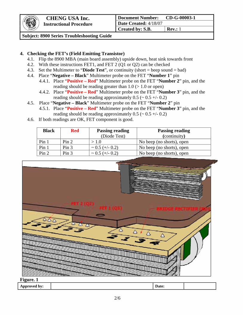
4. Checking the FET’s (Field Emitting Transistor)
4.1. Flip the 8900 MBA (main board assembly) upside down, heat sink towards front 4.2. With these instructions FET1, and FET 2 (Q1 or Q2) can be checked 4.3. Set the Multimeter to “Diode Test”, or continuity (short = beep sound = bad) 4.4. Place “Negative – Black” Multimeter probe on the FET “Number 1” pin
4.4.1. Place “Positive – Red” Multimeter probe on the FET “Number 2” pin, and the reading should be reading greater than 1.0 (> 1.0 or open)
4.4.2. Place “Positive – Red” Multimeter probe on the FET “Number 3” pin, and the reading should be reading approximately 0.5 (~ 0.5 +/- 0.2)
4.5. Place “Negative – Black” Multimeter probe on the FET “Number 2” pin 4.5.1. Place “Positive – Red” Multimeter probe on the FET “Number 3” pin, and the
reading should be reading approximately 0.5 (~ 0.5 +/- 0.2) 4.6. If both readings are OK, FET component is good.
Black Red Passing reading (Diode Test)
Passing reading (continuity)
Pin 1 Pin 2 > 1.0 No beep (no shorts), open Pin 1 Pin 3 ~ 0.5 (+/- 0.2) No beep (no shorts), open Pin 2 Pin 3 ~ 0.5 (+/- 0.2) No beep (no shorts), open
Figure. 1

Document Number: CD-G-00003-1 Date Created: 4/18/07
CHENG USA Inc. Instructional Procedure
Created by: S.B. Rev.: 1 Subject: 8900 Series Troubleshooting Guide
Approved by: Date:
3/6
5. Checking the Bridge Rectifier 5.1. If needed flip the 8900 MBA (main board assembly) upside down, heat sink towards front 5.2. With these instructions Bridge Rectifier (BD1) can be checked 5.3. Set the Multimeter to “Diode Test” or continuity (short = beep sound = bad) 5.4. Place “Negative – Black” Multimeter probe on the Bridge Rectifier “Number 2” pin
5.4.1. Place “Positive – Red” Multimeter probe on the Bridge Rectifier “Number 1” pin, and the reading should be approximately 0.5 (~ 0.5 +/- 0.2)
5.4.2. Place “Positive – Red” Multimeter probe on the Bridge Rectifier “Number 3” pin, and the reading should be approximately 0.5 (~ 0.5 +/- 0.2)
5.5. Place “Negative – Black” Multimeter probe on the Bridge Rectifier “Number 1” pin 5.5.1. Place “Positive – Red” Multimeter probe on the Bridge Rectifier “Number 4” pin,
and the reading should be approximately 0.5 (~ 0.5 +/- 0.2) 5.6. Place “Negative – Black” Multimeter probe on the Bridge Rectifier “Number 3” pin
5.6.1. Place “Positive – Red” Multimeter probe on the Bridge Rectifier “Number 4” pin, and the reading should be approximately 0.5 (~ 0.5 +/- 0.2)
5.7. If all readings are OK, Bridge Rectifier component is good.
Figure. 2
Black Red Reading (Diode Test) Pin 2 Pin 1 0.5 (~ 0.5 +/- 0.2) Pin 2 Pin 3 0.5 (~ 0.5 +/- 0.2) Pin 1 Pin 4 0.5 (~ 0.5 +/- 0.2) Pin 3 Pin 4 0.5 (~ 0.5 +/- 0.2)

Document Number: CD-G-00003-1 Date Created: 4/18/07
CHENG USA Inc. Instructional Procedure
Created by: S.B. Rev.: 1 Subject: 8900 Series Troubleshooting Guide
Approved by: Date:
4/6
6. Checking the onboard leaded Fuse
6.1. Position the 8900 MBA (main board assembly) so that heat sink is to the back 6.2. With these instructions leaded onboard Fuse (F1) can be checked 6.3. Set the Multimeter to “Diode Test” 6.4. Place “Negative – Black” Multimeter probe on one side of the FUSE 6.5. Place “Positive – Red” Multimeter probe on the other side of the FUSE, and the reading
should be approximately “0.0” or short (some Multimeter will beep) 6.6. If the reading is OK, Fuse component is good.
Figure. 3
Document Number: CD-G-00003-1 Date Created: 4/18/07
CHENG USA Inc. Instructional Procedure
Created by: S.B. Rev.: 1 Subject: 8900 Series Troubleshooting Guide
Approved by: Date:
5/6
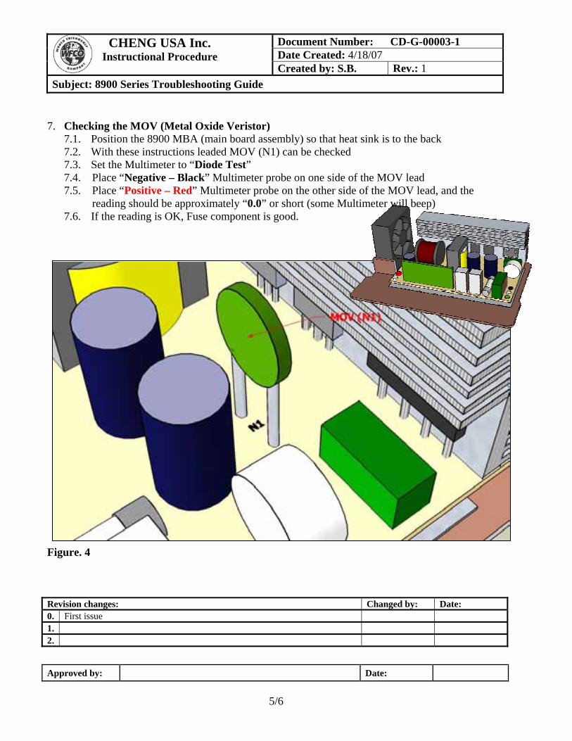
7. Checking the MOV (Metal Oxide Veristor)
7.1. Position the 8900 MBA (main board assembly) so that heat sink is to the back 7.2. With these instructions leaded MOV (N1) can be checked 7.3. Set the Multimeter to “Diode Test” 7.4. Place “Negative – Black” Multimeter probe on one side of the MOV lead 7.5. Place “Positive – Red” Multimeter probe on the other side of the MOV lead, and the
reading should be approximately “0.0” or short (some Multimeter will beep) 7.6. If the reading is OK, Fuse component is good.
Figure. 4
Revision changes: Changed by: Date: 0. First issue 1. 2.

Document Number: CD-G-00003-1 Date Created: 4/18/07
CHENG USA Inc. Instructional Procedure
Created by: S.B. Rev.: 1 Subject: 8900 Series Troubleshooting Guide
Approved by: Date:
6/6
8. Checking the DC Voltage Output NOTE: We recommend that safety glasses should to be used while checking the open PCB while plugged in to AC source.
8.1. With these instructions DC output voltage can be checked 8.2. Let the MBA unit rest on the heat sink, and components facing away, while performing DC
output test 8.3. Apply 110 Vac to the converter input (make sure ground is properly connected) 8.4. Set the Multimeter to “Volts DC” 8.5. Place “Negative – Black” Multimeter probe on the end of “White Output Wire” 8.6. Place “Positive – Red” Multimeter probe on the end of “Red Output Wire”, and the
reading should be approximately “13.6 Vdc +/- 0.2” (14.4 Vdc +/- 0.2 if the unit is in the Bulk charge mode)
8.7. If all steps above have been successfully completed the unit is good.
Revision changes: Changed by: Date: 0. First issue 1. Added use of continuity testing to check components, and safety precautions S.B. 10/14/07 2.