chengjing li 1,*, shucai huang 1, daozhi wei 1, yu zhong 1 ... · chengjing li, shucai huang,...
TRANSCRIPT
Journal of Engineering Science and Technology Review 8 (4) (2015) 105 - 110
Research Article
Detection Range of Airborne Magnetometers in Magnetic Anomaly Detection
Chengjing Li 1,*, Shucai Huang 1, Daozhi Wei 1, Yu Zhong 1, and K. Y. Gong 2
1Air and Missile Defense College, Air Force Engineering University, Xi’an 710051, China
2Department of Electrical and Computer Engineering, Ben-Gurion University of the Negev, Beer-Sheva 84105, Israel
Received 8 March 2015; Accepted 9 November 2015 ___________________________________________________________________________________________ Abstract
Airborne magnetometers are utilized for the small-range search, precise positioning, and identification of the ferromagnetic properties of underwater targets. As an important performance parameter of sensors, the detection range of airborne magnetometers is commonly set as a fixed value in references regardless of the influences of environment noise, target magnetic properties, and platform features in a classical model to detect airborne magnetic anomalies. As a consequence, deviation in detection ability analysis is observed. In this study, a novel detection range model is proposed on the basis of classic detection range models of airborne magnetometers. In this model, probability distribution is applied, and the magnetic properties of targets and the environment noise properties of a moving submarine are considered. The detection range model is also constructed by considering the distribution of the moving submarine during detection. A cell-averaging greatest-of-constant false alarm rate test method is also used to calculate the detection range of the model at a desired false alarm rate. The detection range model is then used to establish typical submarine search probabilistic models. Results show that the model can be used to evaluate not only the effects of ambient magnetic noise but also the moving and geomagnetic features of the target and airborne detection platform. The model can also be utilized to display the actual operating range of sensor systems.
Keywords: detection range, magnetic anomaly detection, search probability __________________________________________________________________________________________ 1. Introduction Magnetometers are the main loads of airborne anti-submarine platforms. These loads are used for the small-range search, precise positioning, and identification of the ferromagnetic properties of underwater targets. Magnetometers are also utilized on the basis of a working principle stating that the presence of a submarine produces an abnormal geomagnetic field in a specific area. Furthermore, magnetometers are suitable for invisible conditions because these instruments passively detect underwater submarines. Compared with sonar buoys, magnetometers are not affected by hydrological and meteorological conditions; as such, magnetometers are more reliable than sonar buoys. Magnetometers are free from the effects of propagation characteristics; these instruments also exhibit strong target discrimination and high-precision positioning. When sea conditions reach above the fifth level, only magnetometers can be used to search for submarines. However, magnetometers cover a small range; furthermore, magnetometers are generally used for confirmation and precise positioning only after other devices have found the approximate location and information of a submarine. Magnetometers can be used for searching when a sea search area is small and narrow or when submarine maneuvering is limited. Therefore, a precise detection range model should be established because of the small range size, especially when detection range is used as a key indicator to assess
submarine search ability, search modes, and chances [1]. Models with various detection ranges, such as acoustic (active and passive sonar buoy systems) and non-acoustic (radar, infrared, laser, and gas detector) detection systems, have been developed [2], [3], [4], [5], [6], [7]. However, reliable and effective models to detect magnetic anomalies have yet to be established. Reference [8] proposed a detection range of static magnetic materials by analyzing specific magnetic anomaly signals. Sheinker A. Reference [9] estimated detection range by simulating the average magnetic moment of targets located in water. Detection range is defined as constant regardless of the influence of environment noise, target magnetic properties, and platform features during the modeling and calculation of submarine search probability; nevertheless, the detection range inevitably deviates from true values and causes errors in probability model calculation [10], [11], [12]. On the basis of a classical detection range model of airborne magnetometers, we introduce probability distribution, consider the target magnetic and environment noise properties of submarines, and establish a novel detection range model. We also consider the distribution of a moving submarine during detection and use a cell-averaging greatest-of-constant false alarm rate (CAGO CFAR) test method to calculate the detection range of the proposed model at a specific false alarm rate. The detection probability in a typical airborne platform extension squareness search program is also simulated and analyzed. The results of the submarine search probability simulation based on this detection range demonstrate the rationality and superiority of the model.
______________ * E-mail address: [email protected] ISSN: 1791-2377 © 2015 Kavala Institute of Technology. All rights reserved.
JOURNAL OF Engineering Science and Technology Review
www.jestr.org
Jestr

Chengjing Li, Shucai Huang, Daozhi Wei, Yu Zhong, and K. Y. Gong/ Journal of Engineering Science and Technology Review 8 (4) (2015) 105- 110
106
2. Detection range of airborne magnetometers based on a target far-field magnetic field model A magnetic anomaly signal is generated when targets are within a detection range. Assuming that airborne magnetometers and targets exhibit a rectilinear motion in a constant direction and at a constant speed within a relatively short period when magnetic anomaly signals emerge, we observe that aircrafts encounter targets at the closest point of approach (CPA) in their route at time 0t . Fig. 1 shows the model of two coordinate systems. The target is located in the grid origin. In this model, o-xyz and oy axis are the geomagnetic north and the magnetic north of the coordinate system, respectively; o-x′y′z′ corresponds to the aeromagnetic detection encounter of the coordinate system; ox′ is parallel to the speed direction of the magnetic detector relative to the target; oz′ is perpendicular to ox′ and points to CPA. The angle between ox and ox′ isφ ; β is the target magnetic heading angle; δ is the angle between oz and oz′; and L and D correspond to the relative vertical distance and the relative horizontal distance between the aircraft and the target, respectively.
CPA
0 ( ,0, )R s R
x
y
z
O
x'
z'
φy'δ
ρ
β
rL
D
Fig. 1. Model of airborne magnetic anomaly detection encounter At different horizontal distances D , the detection probability of the target is (D)dP , and the detection range is defined as follows [13]:
Wm = Pd (D)dD−∞+∞∫ . (1)
Under actual environmental conditions, the detection probability (D)dP of magnetometers cannot be simply demonstrated by applying traditional concepts; in the target horizontal distance D , the target can be detected and the probability is 1. If the target is in the horizontal distance, the detection probability is likely influenced by relative height and target motion parameters, environmental noise, and magnetometer detection algorithm. Therefore, an accurate detection probability model should be established to obtain a precise detection range model. The magnetic anomaly signal model of moving targets detected by magnetometers is analyzed. Assume that the CPA distance is 0R and the coordinates of the aircraft in the o-x′y′z′ coordinate system is ( ,0, )s R , and , ,i j k and ', ', 'i j k are the unit vectors of the three axes in o-xyz and o-x′y′z′ coordinate systems, respectively. In the o-x′y′z′ coordinate system, let the direction cosine of the
target magnetic moment M be , ,l m n and the direction cosine of the geomagnetic field EH be 1 1 1, ,l m n . Then, the unit vector of M can be written as
OX'Y'Z'ˆ l m n= + +M i' j' k' (2)
and the unit vector of EH is
EOX'Y'Z' 1 1 1ˆ l m n= + +H i' j' k' . (3)
Let the aircraft speed be x y zu u u= + +u i j k and the target
speed be x y zρ ρ ρ= + +ρ i j k , the aircraft speed relative to the submarine is
( ) ( ) ( )x x y y z z
x y z
u u uv v v
ρ ρ ρ= − + − + −
= + +
v i j ki j k
(4)
and
2 2arccos , arctany
x y
v DLv
φ δν
= =+
(5)
Assume that the aircraft and submarine have no relative motion in the vertical direction,
2 2 2 20 0( );x ys v t t r s Rν= + − = + , (6)
where r is the distance vector between the target and the detection point. The target is regarded as a magnetic dipole during detection, and the signal measured by the scalar magnetometer is expressed as follows [14]:
( )03
34 rµπ
⋅ −=
r M r MB (7)
The magnetic signal value
MADB detected by the scalar
magnetometer is the target magnetic field in the geomagnetic field projection when MADEH B? expressed as follows:
EMAD
E
BH
=BH
. (8)
Then,
MADB can be written as follows [15]:
20MAD 3
0( )
4i i
iB A f
µω
π == ∑
M
r, (9)
where 7
0 4 10 H/mµ π −= × , and
0 1 1 1 1 1 1 2 1 1 12 ; 3( ); 2A nn ll mm A nl ln A ll mm nn= − − = + = − − (10) and

Chengjing Li, Shucai Huang, Daozhi Wei, Yu Zhong, and K. Y. Gong/ Journal of Engineering Science and Technology Review 8 (4) (2015) 105- 110
107
2 2 2 20 0( ) / ; ( ) / (1 )i
x y iw v t t R f w w wν= + − = + . (11)
The three components of M in the o-xyz coordinate system can be expressed as follows:
E L T
2 2E L E V
| | cos sin cos ( )
| | cos ( cos sin ) | | sinT
x y zM M M k k
k k k
β β
β β
= + + = Φ ⋅ −
+ Φ + − Φ ⋅
M i j k H i
H j H k (12)
where L T V, ,k k k indicate the longitudinal, transverse, and vertical magnetic permeabilities of the target, respectively; and Φ is the geomagnetic inclination. Therefore,
HEOXYZ = cosΦj + sinΦk . (13)
Let cos ,cos yx MMΩ = Θ =
M M; then, the unit vector is
expressed as follows:
OXYZˆ cos sin cos cos sin= Ω Θ + Ω Θ − ΩM i j k . (14)
Thus,
OX'Y'Z' OXYZ
EO'X'Y'Z' EOXYZ
ˆ ˆ
ˆ ˆ=
=
M AM
H AH, (15)
where
sin cos cos cos sincos sin cos sin sin0 sin cos
φ φ δ φ δφ φ δ φ δ
δ δ
⎡ ⎤⎢ ⎥= −⎢ ⎥⎢ ⎥−⎣ ⎦
Α . (16)
The conversion matrix of the coordinate system is expressed in Eq. (16). On the basis of these derivations, we can write the parameters as follows:
cos cos( )cos cos sin( ) sin sinsin cos sin( ) cos sin
lmn
φδ φ δδ φ δ
= Ω −Θ⎧⎪ = Ω −Θ − Ω⎨⎪ = − Ω −Θ − Ω⎩
(17)
1
1
1
cos coscos cos sin sin sinsin cos sin cos sin
lmn
φδ φ δδ φ δ
= Φ⎧⎪ = Φ − Φ⎨⎪ = − Φ − Φ⎩ (18) The residual noise of the process can be adjusted to satisfy Gaussian distribution in a stable flight of an aerial magnetic submarine-searching platform, whose mean is 0 and variance is 2σ , because of the magnetic compensation of instruments in aircrafts. The given false alarm rate fp and detection probability are analyzed on the basis of the magnetic anomaly signals detected by magnetometers. Let the sampling window length of the magnetometer be 2T , the sampling frequency be 2 / (2 )n T , where m is the sampling number, and the output magnetic signals be 1 2 2, , nB B BL . At the false alarm rate fp and the signals MADB , ( )dP D can be calculated by using specific algorithms. The CAGO CFAR test method [16], a constant false alarm rate algorithm [17], is used in this paper to obtain ( )dP D .
Comparator
2nx ! 1nx +2nx + Y nx 1nx − ! 1xInput
Protectioncell
Choiceformula:
1
0T
MultiplierZ1 2max( , )X X
2
11
n
ii n
X x= +
= ∑ 21
n
ii
X x=
=∑
Fig.2. Diagram of the structure of the CAGO CFAR magnetic anomaly signal detector
Fig. 2 shows the structure diagram of the CAGO CFAR magnetic anomaly signal detector. The input signal ix is
defined as 2 , 1,2, ,2i ix B i n= = L ; ix passes successively through a reference window. Y is the cell to be tested and
Chengjing Li, Shucai Huang, Daozhi Wei, Yu Zhong, and K. Y. Gong/ Journal of Engineering Science and Technology Review 8 (4) (2015) 105- 110
108
located in the middle of the reference window, and the cells next to Y are protection cells that can prevent signal energy from leaking to other cells. The remaining reference cells are used to estimate Z . Thus,
2 22 2
1 1 1 1
1 1 1 1Z=max( , ) max( , )N N N N
i i i ii i N i i Nx x B B
N N N N= = + = = +=∑ ∑ ∑ ∑ (19)
For a given false alarm rate fp , the factor T can be calculated from the following equation:
( ) ( ) 11
0
22 1 2 2N N kN
N kkf
k
T T TCN N N
p− − −−
− +
=
⎡ ⎤⎛ ⎞⎢ ⎥+∑ ⎜ ⎟⎢ ⎥⎝ ⎠⎣ ⎦= + − + (20)
Then, let the detection probability of the target (D)dP be
1 1
02 1 2 2 2
(1 ) (1 ) (1 )
N N kN N k
D kk
T T Tp CN N Nλ λ λ
− − −− − +
=
⎡ ⎤⎛ ⎞ ⎛ ⎞ ⎛ ⎞= + − + +⎢ ⎥∑⎜ ⎟ ⎜ ⎟ ⎜ ⎟+ + +⎢ ⎥⎝ ⎠ ⎝ ⎠ ⎝ ⎠⎣ ⎦
(21)
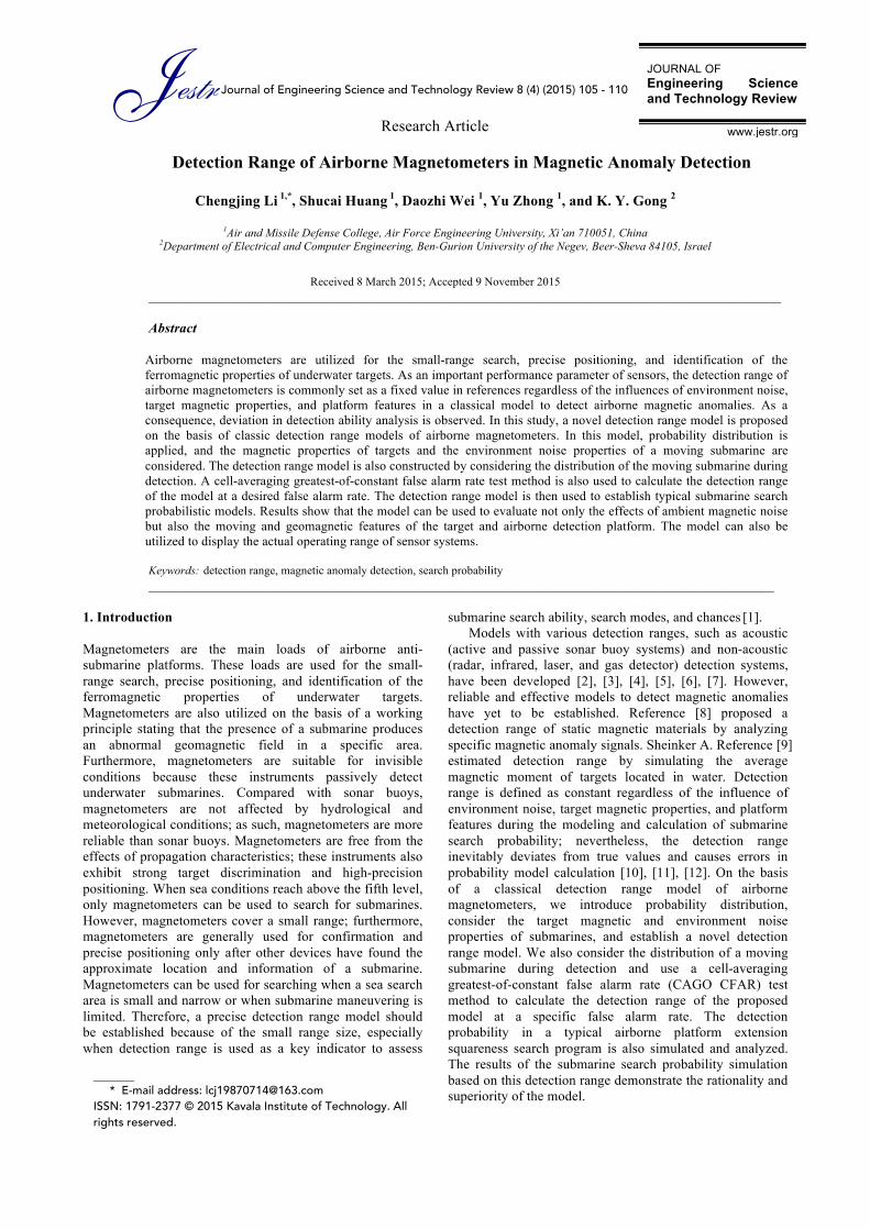
where λ is the average SNR. 3. Search probability model of an airborne platform extension squareness search program The search probability model is based on a previously described method [18]. Fig. 3 shows an airborne platform extension squareness search program. Assume that the initial dispersion of the submarine satisfies bivariate normal distribution; the submarine then maintains an average velocity sev , which satisfies Rayleigh distribution; the submarine headings satisfy uniform distribution at [0,2 ]π interval and the airplane velocity is av . The initial distribution of submarines in the Cartesian coordinate system is expressed as follows:
2
2 2
1( , ) exp( )
2 2
rf r θ
πσ σ−= , (22)
where ( , )r θ is the submarine coordinate in a Cartesian coordinate system. The submarine heading distribution is calculated as follows:
1( ) , [0, 2 ]
2fϕ ϕ ϕ π
π= ∈ . (23)
The probability density function of the submarine velocity is given by Eq. (24):
2
2 2( ) exp( ), 02 4v
se se
v vf v vv vπ π= − ≥ . (24)
Then, the probability density function of submarine position distribution at time t is expressed as follows:
2
0 0
2
2 2 2 2 2 2
( , ; ) [ ( , ), ( , );0]( , , ) ( ) ( )d d
1 exp( )2 ( ) 2( )
vf r t f r v v r t f f v v
rt t
π
ϕθ ϕ θ ϕ θ ϕ ϕ
π σ µ σ µ
+∞=
= −+ +
∫ ∫ (25)
The equivalent cover radius is defined as follows:
as
Dv tR
π= . (26)
The search probability mP can be written as Eq. (27):
00 2
2 2 20
( , ; ) d d
1 exp( )22 ( )
s
mr R
a
se
P f r t r r
Dv t
v t
θ π
θ ϕ
π σπ
≤ ≤≤ ≤
=
= − −+
∫∫ (27)
where D is the detection range, t is the detection time of airplane in the sea search area, and 0σ is the initial dispersion error of the submarine (mean square deviation).
Dsev
av
Searchseaarea
Submarine
Searchpath
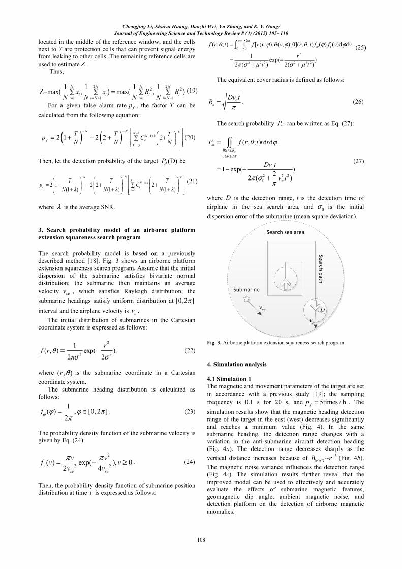
Fig. 3. Airborne platform extension squareness search program 4. Simulation analysis 4.1 Simulation 1 The magnetic and movement parameters of the target are set in accordance with a previous study [19]; the sampling frequency is 0.1 s for 20 s, and 5times / hfp = . The simulation results show that the magnetic heading detection range of the target in the east (west) decreases significantly and reaches a minimum value (Fig. 4). In the same submarine heading, the detection range changes with a variation in the anti-submarine aircraft detection heading (Fig. 4a). The detection range decreases sharply as the vertical distance increases because of 3
MAD ~B r− (Fig. 4b). The magnetic noise variance influences the detection range (Fig. 4c). The simulation results further reveal that the improved model can be used to effectively and accurately evaluate the effects of submarine magnetic features, geomagnetic dip angle, ambient magnetic noise, and detection platform on the detection of airborne magnetic anomalies.

Chengjing Li, Shucai Huang, Daozhi Wei, Yu Zhong, and K. Y. Gong/ Journal of Engineering Science and Technology Review 8 (4) (2015) 105- 110
109
0 50 100 150 200 250 300 350
450
500
550
600
650
700
750
800
850
ΗΕ=52017nT
Φ =35°σ2 =0.15nTL =200m
Dete
ction
rang
e, m
Submarine magnetic heading, deg
φ=30° φ=120° φ=235° φ=320°
a
b
c
Fig.4. Detection range in different submarine magnetic headings
4.2 Simulation 2
Fig.5. Search probability in different vertical distances and submarine magnetic headings
Fig. 5 shows that the pattern of changes in the search probability [Eq. (27)] of the detection range model corresponds to the effect of the geomagnetic field on the magnetic properties of the target. The increase in the vertical distance reduces the search probability. The simulation results can provide an accurate guide for a search plan development. 5. Conclusions Our simulations reveal the influence of the magnetic headings, vertical distance, and ambient magnetic noise of the submarine and the aircraft on the detection range model; in particular, the detection range changes significantly as the magnetic headings of the submarine change. The search probability model of airborne magnetometers uses the proposed detection range and considers the features of the target and the environment; thus, the model can display the actual operating range of sensor systems. This detection range model based on probability distribution can also be used to analyze other sensors. Acknowledgements This work was supported by Natural Science Basic Research Plan in Shaanxi Province of China (2012JM8020).
______________________________
References
1. Han, R. X., Li, C. H., Lu Q. F., “Simulation formagnetic anomaly detection in air antisubmarine”, Journal of System Simulation, 21(9), 2009, pp. 2753-2756.
2. Marszal, J., Salamon, R., “Detection range of intercept sonar for CWFM signals”, Archives of Acoustics, 39(2), 2014, pp. 215-230.
3. Samaran, F., Adam, O., Guinet, C., “Detection range modeling of blue whale calls in Southwestern Indian Ocean”, Applied Acoustics, 71 (11), 2010, pp. 1099-1106.
4. Wang, W. H., Niu, Z. D., Chen, Z. P., “Research on the operating range of staring IR imaging system in sea-sky background”, Journal of Infrared and Millimeter Waves, 25(2), 2006, pp. 150-152.
5. Wegener, I., “The discrete search problem and the construction of optimal location”, Naval Research Logistics Quarterly, 29(2), 1982, pp. 533-543.
6. Hirota, M., Furuse, T., Ebana, K., “Magnetic detection of a surface ship by an airborne LTS squid MAD”, IEEE Transactions on Applied Superconductivity, 11(1), 2001, pp. 884-887.
7. Jia, Q., Qiao, Y., Deng, W., “Analysis forpoint-target detection range of panoramic searching system”, Acta Optical Sinica, 29(4), 2009, pp. 937-942.
8. Ege, Y., Kalender, O., Nazlibilek, S., “Direction finding of moving ferromagnetic objects inside water by magnetic anomaly”, Sensors and Actuators, A: Physical, 147 (1), 2008, pp. 52-59.

Chengjing Li, Shucai Huang, Daozhi Wei, Yu Zhong, and K. Y. Gong/ Journal of Engineering Science and Technology Review 8 (4) (2015) 105- 110
110
9. Sheinker, A., Lerner, B., Salomonski, N., “Localization and magnetic moment estimation of a ferromagnetic target by simulated annealing”, Measurement Science and Technology, 18(11), 2007, pp. 3451-3457.
10. Hristoforou, E., “Magnetic effects in physical sensor design and development”, Journal of Optoelectronics and Advanced Materials, 4(2), 2004, pp. 245-265.
11. Mu, D., Wang J., Chen, T., “Analysis on operating range of a staring infrared search and track system for armed helicopter”, Acta Armamentarii, 29(3), 2008, pp. 313-317.
12. Wu F., Yang, R. J., Zhou, X., , “Study on the answer submarine search efficiency of aerial magnetic detection”, Journal of Test and Measurement Technology, 22(2), 2008, pp. 114-117.
13. Yang, R. J., Xiong, X., Guo, X. Q., Han, J. H., “Research on model and simulation of airborne magnetic anomaly detection sweep width based on magnetic dipole model”, Acta Armamentarii, 35(9), 2014, pp. 1459-1465.
14. Sheinker, A., Frumkis, L., Ginzburg, B., “Magnetic anomaly detection using a three-axis magnetometer”, IEEE Transactions on Magnetics, 45(1), 2009, pp.160-167.
15. Sheinker, A., Ginzburg, B., Salomonski, N., “Magnetic anomaly detection using high-order crossing method”, IEEE Transactions on Geoscience and Remote Sensing, 50(4), 2012, pp. 1095-1101.
16. Blake, S., “CFAR theory for multiple targets and nonuniform clutter”, IEEE Transactions on AES, 24(6), 1988, pp. 785-790.
17. He, Y., Meng, X. W., “A new Greatest selection CFAR detector based on ordered statistics and trimmed mean”, Electronica Sinica, 26(3), 1998, pp. 227-232.
18. Qu, Y. P., Liao, Y., “Research on modeling of submarine's position distribution and search probability in anti-submarine warfare”, Journal of System Simulation, 20(12), 2008, pp. 3280-3283.
19. Chen, C., Wei, Y., Yao, L. F., Jiang, Z. G., Gong, S. G., “Estimation and simulation analysis of the submarine magnetic field based on current-line mode”, Journal of Electronics & Information Technology, 37(2), 2015, pp. 461-467.