cherrymax rivet - n2999c · 2 cherrymax® rivet features x the cherrymax® rivet is inserted into...
TRANSCRIPT

CHERRYMAX ® RIVET
U.S. PATENT NO. 4012984
WARRANTYX
WARRANTY
ATTENTION:Important: Blind fasteners are not always interchangeable with non-blind fasteners. Consult with the aircraft original equipment manufacturer for proper application of this product.
Reproduction or duplication of the copyrighted document without the expressed written consentof Textron Fastening Systems is prohibited. CR®, Cherry®, CherryMAX®, CherryLOCK®, ‘A’ areregistered trademarks of Textron Fastening Systems.
© 2003 Copyright Textron Fastening Systems
Cherry® and CherryMax® are registered trademarks of Textron Inc.
Supplier’s Federal Identification Code-11815
Textron Fastening Systems, a Division of Textron Inc. (hereinafter “TFS”).hereby warrants to the initial retail customer (“Warrantee”) only that itsproducts wiII be free from defects in material and workmanship, providedthat the products are used in accordance with TFS’s instruction as to main-tenance, operation and use. The foregoing warranty is limited to productsthat are in the original container and the duration of the warranty is limitedto 90 days from the date of first use by the Warrantee.
This Warrantee’s only remedy and TFS’s only obligation in the event of adefect or failure in the products, is that TFS will, at its sole option, repair,replace, or rework the products, but in no case shall the cost of the fore-going exceed the invoice price of the products.
This Warranty shall be void if any person seeking to make a claim fordefective or failed products fails to notify TFS within thirty (30) days afterreceipt of evidence that the product is defective or has failed, or if said per-son fails to provide TFS with such evidence as is reasonably requestedconcerning the defect or failure, including without limitation, evidence ofthe date of purchase and date of installation.
THIS WARRANTY IS IN LIEU OF ALL OTHER WARRANTIES,EXPRESSED OR IMPLIED, INCLUDING MERCHANTABILITY OR FIT-NESS FOR A PARTICULAR PURPOSE. TFS EXPRESSLY DISCLAIMSLIABILITY FOR ALL INCIDENTAL, CONSEQUENTIAL, OR SPECIALDAMAGES ARISING FROM ANY DEFECT OR FAILURE IN ITS PROD-UCTS. TAF FURTHER DISCLAIMS ALL LIABILITY RESULTING FROMTHE USER’S CHOICE OF ITS PRODUCTS FOR ANY PARTICULARAPPLICATION.
The properties, strengths, dimensions, installed characteristics and allother information in this catalog is for guidance only to aid in the correctselection of the products described herein and is not intended or impliedas part of the above warranty. All applications should be evaluated by theuser of the products for functional suitability and evaluations.

INDEXX
CHERRYMAX® RIVET FEATURES AND BENEFITS ..........................2-3
CHERRYMAX® RIVET SELECTION
NUMBERING SYSTEM / HEAD STYLES........................................4
DIAMETER/GRIP SYSTEM..............................................................5
MECHANICAL PROPERTIES / GAGES ..........................................6
WEIGHT PER 1000 PIECES BY RIVET SIZE .................................7
CHERRYMAX® RIVET STANDARDS PAGES
NOMINAL SHANK
UNIVERSAL HEAD ..........................................................................8
100° FLUSH HEAD ..........................................................................9
100° FLUSH SHEAR HEAD (NAS 1097).......................................10
OVERSIZE SHANK DIAMETER
UNIVERSAL HEAD ........................................................................11
100° FLUSH HEAD ........................................................................12
UNISINK HEAD ..............................................................................13
120° FLUSH HEAD ........................................................................14
CHERRYMAX® RIVET INSTALLATION & INSPECTION ................15-17
CHERRYMAX® RIVET lNSTALLATION TOOLING
TOOL SELECTION ........................................................................19
HAND RIVETERS AND KITS.........................................................20
POWER RIVETERS .......................................................................21
SPLIT POWER RIVETERS ............................................................22
PULLING HEADS...........................................................................23
EXTENSIONS, ADAPTERS & ACCESSORIES........................24-25

2
CHERRYMAX® RIVET FEATURESX
➀ The CherryMAX® Rivet isinserted into the prepared hole.The pulling head (installationtool) is slipped over the rivet’sstem. Applying a firm, steadypressure, which seats the rivethead, the installation tool is thenactuated.
➁ The pulling head holds therivet sleeve in place as it beginsto pull the rivet stem into the rivetsleeve. This pulling action causes the stem shear ring toupset the rivet sleeve and formthe “bulbed” blind head.
➂ The continued pulling actionof the installation tool causes thestem shear ring to shear from themain body of the stem as thestem continues to move thru therivet sleeve. This action allowsthe fastener to accommodate aminimum of 1/16" variation instructure thickness. The LockingCollar then contacts the DrivingAnvil. As the stem continues tobe pulled by the action of theinstallation tool, the “Safe-lock”Locking Collar deforms into therivet sleeve head recess.Formation of the rivet sleeve’s“bulbed” blind head is complete.
➃ The “Safe-lock” LockingCollar fills the rivet sleeve headrecess, locking the stem andrivet sleeve securely together.Continued pulling by the installation tool causes the stemto fracture at the break notch,providing a flush, burr-free,inspectable installation.
The CherryMAX® Rivet is the most reliable,high strength structural fastener with visualinspectability in the world today. It features the“Safe-lock” Locking Collar for more reliablejoint integrity. Meets requirements of PS-CMR-3000.
CherryMAX® Rivets consists of four components assembled as a single unit:
1. A fully serrated stem with break notch,shear-ring and integral grip adjustment cone.
2. A driving anvil to insure a visible mechanical lock with each fastener installation.
3. A separate, visible and inspectable lockingcollar that mechanically locks the stem tothe rivet sleeve.
4. A rivet sleeve with recess in the head toreceive the locking collar
Covered by U.S. Patent No. 4012984
INSTALLATION
X

3
CHERRYMAX® RIVET BENEFITSX
DRIVING ANVILA driving anvil is part of each CherryMAX® Rivet assembly.This Driving Anvil eliminates wear and replacement of expend-able installation tool components, considerably extending thelife of the installation tool.
It also allows one pulling head to install:
• 1⁄8", 5⁄32", and 3⁄16" Nominal and Oversize Diameter Rivets.
• Protruding, 100° Flush and 100° Flush Shear, Unisink, and120° Flush Head Styles
• All CherryMAX® Rivet grip lengths
• All CherryMAX® Rivet sleeve/stem material combinations
LOCKING COLLAR The CherryMAX® Rivet features the patented “Safe-Lock”Locking Collar which enhances joint integrity and reliability.
The “Safe-lock” Locking Collar is preformed on the stem duringa sub-assembly operation, then deforms into the rivet sleevehead recess during installation, locking the rivet sleeve andstem together.
The “Safe-lock” Locking Collar is visible and inspectable after installation.
The “Safe-lock” Locking Collar installs flush with the rivetsleeve head.
The “Safe-lock” Locking Collar has been approved by severalOEM’s for use in engine inlets and components.
RIVET The CherryMAX® Rivet is available in both nominal and 1⁄64"oversize shank diameters and is available in four materialcombinations:
• 5056 Aluminum Sleeve/Alloy Steel Stem (50KSI Shear)
• 5056 Aluminum Sleeve/Cres Stem (50KSI Shear)
• Monel Sleeve/Cres Stem (75KSI Shear)
• INCO 600 Sleeve/INCO X-750 Stem (75KSI Shear)
TOOLING SIMPLICITYLightweight, non-shifting installation tools require no adjusting.
Limited access capability with Right Angle and Offset PullingHeads and Extensions for greater reach and “Split” tools forspecial applications including automation and robotics.
BULBED BLIND HEAD Provides a large bearing surface area on the blind side of thestructure, giving dependable results, even when installed in difficult thin sheet stack-up applications.

4
CHERRYMAX® RIVET SELECTIONX
NUMBERING SYSTEM
UNIVERSAL(MS20470)
For protruding head applicationsAvailable in both nominal & oversize
100° FLUSH(MS20426)
For countersunk applicationsAvailable in both nominal & oversize
100° FLUSH(NAS1097)
For thin top sheet, machine countersunk applicationsAvailable in nominal only
UNISINKA combination flush and protrudinghead for use in very thin top sheets.Eliminates need for double-dimpling.
Available in oversize only
120° FLUSHA large diameter, shallow flush headproviding a wide bearing area in thin
top sheet applications.Available in oversize only
CHERRY PART NUMBER EXAMPLE:
HEAD STYLES
CR3 24 2—6—04
Maximum Grip Length in 16ths of an inch(-04 = 4/16 = 1/4)
Rivet Diameter in32nds if an inch(-6 = 6/32 = 3/16
Head StyleOdd number = Protruding HeadEven number = Flush Head
Rivet Type & Material Combination(See Pages 7 thru 13)
Cherrymax Rivet
5
CHERRYMAX® RIVET SELECTIONX
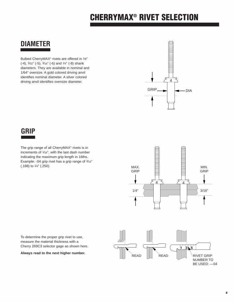
DIAMETER
Bulbed CherryMAX® rivets are offered in 1⁄8" (-4), 5⁄32" (-5), 3⁄16" (-6) and 1⁄4" (-8) shankdiameters. They are available in nominal and1/64" oversize. A gold colored driving anvilidentifies nominal diameter. A silver coloreddriving anvil identifies oversize diameter.
GRIP
The grip range of all CherryMAX® rivets is inincrements of 1⁄16", with the last dash numberindicating the maximum grip length in 16ths.Example: -04 grip rivet has a grip range of 3⁄16"(.188) to 1⁄4" (.250).
To determine the proper grip rivet to use,measure the material thickness with a Cherry 269C3 selector gage as shown here.
Always read to the next higher number.
DIAGRIP
1/4"
MAX.GRIP
3/16"
MIN.GRIP
READ READ RIVET GRIPNUMBER TOBE USED: —04
4 4
4

MECHANICAL PROPERTIES*
CHERRYMAX® RIVET SELECTIONX
6
MATERIALS ULTIMATE MAXIMUM
SLEEVE STEM SHEAR STRENGTH TEMPERATURE
5056 Aluminum Alloy Steel 50,000 psi 250° F
5056 Aluminum CRES 50,000 psi 250° F
Monel CRES 75,000 psi 900° F
Inco 600 Inco X-750 75,000 psi 1400° F
SINGLE SHEAR TENSILE
ALUMINUM MONEL INCO ALUMINUM MONEL INCO
NOM. O/S NOM. O/S O/S NOM. O/S NOM. O/S O/S
3212 3242 3522 3552 3852 3212 3214 3242 3522 3524 3552 3852
3213 3243 3523 3553 3853 3213 3224 3243 3523 3553 3853
RIVET SHEET 3214 3245 3524 3555 3222 3245 3555
DIAM. THICK. 3222 3246 3556 3223 3246 3556
3223 3252 3252
3224 3253 3253
3255 32551⁄8(-4) 2x.156 664 814 995 1220 1220 285 250 345 400 360 490 570
5⁄32(-5) 2x.187 1030 1245 1545 1865 1865 445 390 530 635 555 740 8603⁄16(-6) 2x.219 1480 1685 2215 2525 2525 635 560 710 890 800 1000 11601⁄4(-8) 2x.281 2615 2925 3920 4390 4390 1125 1000 1260 1570 1410 1755 2030
RIVET GAGE NATIONAL RIVET GAGE NATIONALDIAMETER NUMBER STOCK NO. DIAMETER NUMBER STOCK NO.
1/8" Nominal T-172-4 5220-00-478-4135 1/8" Oversize T-172-400 5220-00-478-4127
5/32" Nominal T-172-5 5220-01-021-3276 5/32" Oversize T-172-500 5220-00-478-4140
3/16" Nominal T-172-6 5220-00-478-4136 3/16" Oversize T-172-600 5220-00-478-4141
1/4" Nominal T-172-8 5220-00-478-4139 1/4" Oversize T-172-800 5220-01-374-1340
GAGES
269C3 GRIP GAGENational Stock Number 5210-00-255-7544A simple, self-explanatory gage for determining material thickness and proper river grip length.
T-172 RIVET HOLE SIZE GAGEThese are precision ground, go-no-go gages used to checkholes drilled for CherryMAX® rivets. They are made in bothnominal and oversize rivet diameters.
* At room temperature

CHERRYMAX® RIVET SELECTIONX
7
ALUMINUM MONEL INCO 600
NOMINAL OVERSIZE NOMINAL OVERSIZE OVERSIZE
3212* 3213 3242* 3243 3522* 3523 3552 3553 3852* 3853RIVET DIAMETER 3214* 3223 3246* 3245 3524* 3556* 3555
AND GRIP LENGTH 3222* 3252* 32533224* 3255
-01 .59 .69 .75 .88 — 1.28 1.10 1.32 — 1.35-02 .59 .79 .85 .99 1.05 1.52 1.14 1.58 1.16 1.61-03 .71 .93 .97 1.16 1.24 1.74 1.42 1.86 1.44 1.88
-4 (1/8") -04 .86 1.07 1.14 1.33 1.44 1.90 1.70 2.14 1.72 2.17-05 1.00 1.21 1.31 1.50 1.66 2.16 1.98 2.42 2.01 2.44-06 1.14 1.36 1.47 1.66 1.88 2.38 2.26 2.70 2.28 2.73-07 1.28 1.50 1.64 1.83 2.00 2.61 2.54 2.98 2.56 3.02-08 1.42 1.64 1.81 2,00 2.22 2.83 2.82 3.26 2.89 3.29-09 1.56 1.78 1.98 2.17 2.44 3.05 3.10 3.54 3.22 3.66
-01 — 1.26 — 1.55 — 2.41 — 2.46 — 2.53-02 1.02 1.41 1.34 1.71 1.84 2.81 1.87 2.90 1.99 2.98-03 1.22 1.63 1.56 1.98 2.15 3.14 2.26 3.34 2.37 3.44-04 1.45 1.86 1.82 2.24 2.50 3.46 2.87 3.78 2.90 3.91
-5 (5/32") -05 1.67 2.08 2.09 2.51 2.86 3.81 3.30 4.22 3.33 4.26-06 1.90 2.31 2.36 2.78 3.22 4.17 3.74 4.66 3.85 4.77-07 2.12 2.53 2.63 3.05 3.58 4.53 4.18 5.10 4.31 5.21-08 2.35 2.75 2.90 3.32 3.94 4.92 4.62 5.54 4.75 5.67-09 2.57 2.98 3.16 3.58 4.29 5.24 5.06 5.98 5.19 6.13-10 2.79 3.20 3.43 3.85 4.64 5.56 5.50 6.42 5.63 6.55-11 3.01 3.42 3.70 4.12 4.99 5.87 5.94 6.86 6.07 6.97
-01 2.01 — 2.39 3.84 — 3.99 — 4.13-02 1.75 2.20 2.00 2.58 3.04 4.38 3.12 4.51 3.24 4.65-03 2.00 2.52 2.28 2.93 3.54 4.87 3.69 5.08 3.82 5.22-04 2.33 2.85 2.62 3.27 4.04 5.38 4.27 5.66 4.33 5.80-05 2.64 3.16 2.97 3.62 4.54 5.86 4.85 6.24 4.97 6.37
-6 (3/16") -06 2.97 3.49 3.32 3.97 5.04 6.36 5.43 6.82 5.55 6.95-07 3.28 3.80 3.67 4.32 5.54 6.86 6.01 7.40 6.13 7.53-08 3.61 4.13 4.02 4.67 6.04 7.36 6.59 7.98 6.72 8.11-09 3.93 4.45 4.36 5.01 6.54 7.86 7.17 8.56 7.30 8.69-10 4.25 4.77 4.71 5.36 7.04 8.35 7.75 9.14 7.88 9.27-11 4.57 5.09 5.06 5.71 7.54 8.85 8.33 9.72 8.47 9.85-12 4.90 5.42 5.41 6.06 8.04 9.34 8.91 10.30 9.05 10.44
-02 — 4.79 — — — 9.17 — 9.92 10.28-03 4.08 5.35 4.50 5.74 6.98 10.01 7.45 10.95 7.73 11.37-04 4.61 5.92 5.32 6.57 7.63 10.80 8.58 11.98 8.90 12.42-05 5.14 6.49 5.71 7.14 8.98 12.29 9.71 13.01 10.07 13.41
-8 (1/4") -06 5.67 7.06 6.28 7.81 10.04 13.28 10.84 14.04 11.24 14.54-07 6.20 7.63 6.91 8.48 11.05 14.20 11.97 15.07 12.38 15.67-08 6.73 8.19 7.54 9.11 12.38 15.26 13.10 16.10 13.62 16.70-09 7.26 8.76 8.17 9.74 13.01 16.25 14.23 17.13 14.80 17.73-10 7.79 9.33 8.80 10.37 13.64 17.23 15.36 18.16 15.96 18.76-11 8.32 9.90 9.43 11.00 15.81 18.21 16.49 19.19 17.09 19.79-12 8.85 10.47 10.06 11.63 16.78 19.18 17.62 20.22 18.24 20.82-13 9.36 11.03 10.69 12.26 17.73 20.13 18.75 21.25 19.36 21.86-14 9.91 11.60 11.32 12.89 18.69 21.09 19.88 22.28 20.51 22.89
INSTALLED WEIGHTS - Pounds per 1000 pieces (Ref.)
*
*No 4-01 grip.
8
GRIP LIMITS1/16 -4(1/8”) DIAMETER -5(5/32”) DIAMETER -6(3/16”) DIAMETER -8(1/4”) DIAMETER
DASH +.000 K DASH +.000 K DASH +.000 K DASH +.000 KMIN. MAX. NO. L -.030 MAX NO. L -.030 MAX NO. L -.030 MAX NO. L -.030 MAX
➀ .062 4-01 .161 .38 5-01 .187 .41 6-01 .219 .47.063 .125 4-02 .224 .45 5-02 .230 .47 6-02 .262 .51 8-02 .315 .59.126 .187 4-03 .287 .51 5-03 .293 .53 6-03 .325 .57 8-03 .378 .65.188 .250 4-04 .349 .57 5-04 .355 .59 6-04 .387 .64 8-04 .440 .72.251 .312 4-05 .412 .63 5-05 .418 .65 6-05 .450 .70 8-05 .503 .78.313 .375 4-06 .474 .70 5-06 .480 .72 6-06 .512 .76 8-06 .565 .84.376 .437 4-07 .537 .76 5-07 .543 .77 6-07 .575 .82 8-07 .628 .90.438 .500 4-08 .599 .82 5-08 .605 .84 6-08 .637 .88 8-08 .690 .97.501 .562 4-09 .662 .88 5-09 .668 .90 6-09 .700 .95 8-09 .753 1.03.563 .625 5-10 .730 .96 6-10 .762 1.01 8-10 .815 1.09.626 .687 5-11 .793 1.02 6-11 .825 1.07 8-11 .878 1.15.688 .750 6-12 .887 1.13 8-12 .940 1.22.751 .812 8-13 1.003 1.28.813 .875 8-14 1.065 1.34
MATERIAL ➂ FINISHRIVET
NUMBER SLEEVE STEM LOCK COLLAR SLEEVE STEM LOCK COLLAR5056 8740 A-286 CHEM FILM CAD PLATE
CR3213 ALUM. ALLOY ALLOY STEEL CRES MIL-C-5541 QQ-P-416QQ-A-430 AMS 6322 AMS 5731 PLAIN COLOR TYPE II CL. 2
5056 15-7 PH A-286 CHEM FILMCR3223 ALUM. ALLOY CRES CRES MIL-C-5541
QQ-A-430 AMS 5657 AMS 5731 PLAIN COLORMONEL 15-7 PH A-286 PASSIVATE
CR3523 QQ-N-281 CRES CRES NONE NONE QQ-P-35AMS 5657 AMS 5731
MONEL MONEL 15-7 PH ALUM. COATCR3523P QQ-N-281 CRES CRES MIL-C-83488 NONE
AMS 5657 AMS 5731MONEL 15-7 PH A-286 ALUM. COAT
CR3523EE QQ-N-281 CRES CRES NAS4006 & NONEAMS 5657 AMS 5731 BMS10-85
NOTES: ➀ Minimum grip for: -4 dia. = .025Minimum grip for: -5 dia. = .031Minimum grip for: -6 dia. = .037
2. Do not clean or degrease prior to installation - lubricant must not be removed.
➂ Chemical composition only.
➃ Gold colored driving anvil identifies nominal rivets.
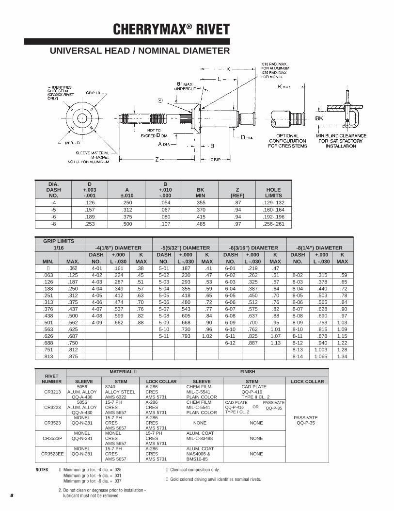
DIA. D BDASH +.003 A +.010 BK Z HOLENO. -.001 ±.010 -.000 MIN (REF) LIMITS-4 .126 .250 .054 .355 .87 .129-.132-5 .157 .312 .067 .370 .94 .160-.164-6 .189 .375 .080 .415 .94 .192-.196-8 .253 .500 .107 .485 .97 .256-.261
CHERRYMAX® RIVETUNIVERSAL HEAD / NOMINAL DIAMETER
CAD PLATEQQ-P-416TYPE I CL. 2
PASSIVATEQQ-P-35OR

9
CHERRYMAX® RIVET100° FLUSH HEAD / NOMINAL DIAMETER
GRIP LIMITS1/16 -4(1/8”) DIAMETER -5(5/32”) DIAMETER -6(3/16”) DIAMETER -8(1/4”) DIAMETER
DASH +.000 K DASH +.000 K DASH +.000 K DASH +.000 KMIN. MAX. NO. L -.030 MAX NO. L -.030 MAX NO. L -.030 MAX NO. L -.030 MAX
➁ .125 4-02 .224 .45 5-02 .230 .47 6-02 .262 .51.126 .187 4-03 .287 .51 5-03 .293 .53 6-03 .325 .57 8-03 .378 .65.188 .250 4-04 .349 .57 5-04 .355 .59 6-04 .387 .64 8-04 .440 .72.251 .312 4-05 .412 .63 5-05 .418 .65 6-05 .450 .70 8-05 .503 .78.313 .375 4-06 .474 .70 5-06 .480 .72 6-06 .512 .76 8-06 .565 .84.376 .437 4-07 .537 .76 5-07 .543 .77 6-07 .575 .82 8-07 .628 .90.438 .500 4-08 .599 .82 5-08 .605 .84 6-08 .637 .88 8-08 .690 .97.501 .562 4-09 .662 .88 5-09 .668 .90 6-09 .700 .95 8-09 .753 1.03.563 .625 - - - 5-10 .730 .96 6-10 .762 1.01 8-10 .815 1.09.626 .687 - - - 5-11 .793 1.02 6-11 .825 1.07 8-11 .878 1.15.688 .750 - - - - - - 6-12 .887 1.13 8-12 .940 1.22.751 .812 - - - - - - - - - 8-13 1.003 1.28.813 .875 - - - - - - - - - 8.14 1.065 1.34
MATERIAL ➃ FINISHRIVET
NUMBER SLEEVE STEM LOCK COLLAR SLEEVE STEM LOCK COLLAR5056 8740 A-286 CHEM FILM CAD PLATE
CR3212 ALUM. ALLOY ALLOY STEEL CRES MIL-C-5541 QQ-P-416QQ-A-430 AMS 6322 AMS 5731 PLAIN COLOR TYPE II CL. 2
5056 15-7 PH A-286 CHEM FILMCR3222 ALUM. ALLOY CRES CRES MIL-C-5541
QQ-A-430 AMS 5657 AMS 5731 PLAIN COLORMONEL 15-7 PH A-286 PASSIVATE
CR3522 QQ-N-281 CRES CRES NONE NONE QQ-P-35AMS 5657 AMS 5731
MONEL 15-7 PH A-286 ALUM. COATCR3522P QQ-N-281 CRES CRES MIL-C-83488 NONE
AMS 5657 AMS 5731 AMS 5731MONEL 15-7 PH A-286 ALUM. COAT
CR3522EE QQ-N-281 CRES CRES NAS4006 & NONEAMS 5657 AMS 5731 BMS10-85
NOTES: ➀ Head diameters are to theoretical projection.
➁ Minimum grip for: -4 dia. = .063Minimum grip for: -5 dia. = .065Minimum grip for: -6 dia. = .080
3. Do not clean or degrease prior to installation - lubricant must not be removed.
➃ Chemical composition only.
➄ Gold colored driving anvil identifies nominal rivets.
DIA. D CDASH +.003 A➀ B BK Z HOLENO. -.001 ±.004 (REF) MIN (REF) ALUM MONEL LIMITS-4 .126 .225 .041 .355 .87 .002-.010 .005-.015 .129-.132-5 .157 .286 .054 .370 .94 .002-.012 .005-.015 .160-.164-6 .189 .353 .069 .415 .94 .002-.012 .005-.015 .192-.196-8 .253 .476 .095 .485 .97 .002-.016 .005-.015 .256-.261
CAD PLATEQQ-P-416TYPE I CL. 2
PASSIVATEQQ-P-35OR
HEAD MARKINGS VISIBLE AFTER INSTALLATION

10
CHERRYMAX® RIVETNAS 1097 100° FLUSH SHEAR HEAD / NOMINAL DIAMETER
GRIP LIMITS1/16 -4(1/8”) DIAMETER -5(5/32”) DIAMETER -6(3/16”) DIAMETER -8(1/4”) DIAMETER
DASH +.000 K DASH +.000 K DASH +.000 K DASH +.000 KMIN. MAX. NO. L -.030 MAX NO. L -.030 MAX NO. L -.030 MAX NO. L -.030 MAX.045 .062 4-01 .221 .45➁ .125 4-02 .224 .45 5-02 .230 .47 6-02 .262 .51
.126 .187 4-03 .287 .51 5-03 .293 .53 6-03 .325 .57 8-03 .378 .65
.188 .250 4-04 .349 .57 5-04 .355 .59 6-04 .387 .64 8-04 .440 .72
.251 .312 4-05 .412 .63 5-05 .418 .65 6-05 .450 .70 8-05 .503 .78
.313 .375 4-06 .474 .70 5-06 .480 .72 6-06 .512 .76 8-06 .565 .84
.376 .437 4-07 .537 .76 5-07 .543 .77 6-07 .575 .82 8-07 .628 .90
.438 .500 4-08 .599 .82 5-08 .605 .84 6-08 .637 .88 8-08 .690 .97
.501 .562 4-09 .662 .88 5-09 .668 .90 6-09 .700 .95 8-09 .753 1.03
.563 .625 5-10 .730 .96 6-10 .762 1.01 8-10 .815 1.09
.626 .687 5-11 .793 1.02 6-11 .825 1.07 8-11 .878 1.15
.688 .750 6-12 .877 1.13 8-12 .940 1.22
.751 .812 8-13 1.003 1.28
.813 .875 8-14 1.065 1.34
MATERIAL ➄ FINISHRIVET
NUMBER SLEEVE STEM LOCK COLLAR SLEEVE STEM LOCK COLLAR5056 8740 A-286 CHEM FILM CAD PLATE
CR3214 ALUM. ALLOY ALLOY STEEL CRES MIL-C-5541 QQ-P-416QQ-A-430 AMS 6322 AMS 5731 PLAIN COLOR TYPE II CL. 2
5056 15-7 PH A-286 CHEM FILMCR3224 ALUM. ALLOY CRES CRES MIL-C-5541
QQ-A-430 AMS 5657 AMS 5731 PLAIN COLORMONEL 15-7 PH A-286 PASSIVATE
CR3524 QQ-N-281 CRES CRES NONE NONE QQ-P-35AMS 5657 AMS 5731
MONEL 15-7 PH A-286 ALUM. COATCR3524P QQ-N-281 CRES CRES MIL-C-83488 NONE
AMS 5657 AMS 5731MONEL 15-7 PH A-286 ALUM. COAT
CR3524EE QQ-N-281 CRES CRES NAS4006 & NONEAMS 5657 AMS 5731 BMS10-85
CAD PLATEQQ-P-416TYPE I CL. 2
PASSIVATEQQ-P-35OR
DIA. D CDASH +.003 A ➀ B BK Z HOLENO. -.001 ±.004 (REF) MIN (REF) ALUM MONEL LIMITS-4 .126 .192 .028 .355 .87 .002-.010 .005-.015 .129-.132-5 .157 .243 .037 .370 .94 .002-.012 .005-.015 .160-.164-6 .189 .299 .046 .415 .94 .002-.012 .005-.015 .192-.196-8 .253 .392 .060 .485 .97 .002-.016 .005-.015 .256-.261
NOTES: ➀ Head diameters are to theoretical projection.
➁ Minimum grip for: -4 dia. = .063Minimum grip for: -5 dia. = .065Minimum grip for: -6 dia. = .080
➂ -6 and -8 diameter marking only; square depressed marking withdots identifies Cherrymax -4 and -5 diameters.
4. Do not clean or degrease prior to installation - lubricant must not be removed.
➄ Chemical composition only.
➅ Gold colored driving anvil identifies nominal rivets.
HEAD MARKINGS VISIBLE AFTER INSTALLATION

11
GRIP LIMITS1/16 -4(1/8”) DIAMETER -5(5/32”) DIAMETER -6(3/16”) DIAMETER -8(1/4”) DIAMETER
DASH +.000 K DASH +.000 K DASH +.000 K DASH +.000 KMIN. MAX. NO. L -.030 MAX NO. L -.030 MAX NO. L -.030 MAX NO. L -.030 MAX
➀ .062 4-01 .175 .37 5-01 .203 .43 6-01 .242 .45.063 .125 4-02 .238 .46 5-02 .246 .47 6-02 .265 .50 8-02 .313 .57.126 .187 4-03 .301 .52 5-03 .309 .53 6-03 .328 .55 8-03 .375 .64.188 .250 4-04 .363 .58 5-04 .371 .60 6-04 .390 .62 8-04 .437 .70.251 .312 4-05 .426 .65 5-05 .434 .66 6-05 .453 .68 8-05 .500 .77.313 .375 4-06 .488 .71 5-06 .496 .72 6-06 .515 .74 8-06 .562 .83.376 .437 4-07 .551 .78 5-07 .559 .79 6-07 .578 .82 8-07 .625 .89.438 .500 4-08 .613 .84 5-08 .621 .85 6-08 .640 .89 8-08 .687 .95.501 .562 4-09 .676 .90 5-09 .684 .91 6-09 .703 .95 8-09 .750 1.02.563 .625 5-10 .746 .98 6-10 .765 1.01 8-10 .812 1.08.626 .687 5-11 .809 1.04 6-11 .828 1.07 8-11 .875 1.14.688 .750 6-12 .890 1.14 8-12 .937 1.20.751 .812 8-13 1.000 1.27.813 .875 8-14 1.062 1.60
MATERIAL ➂ FINISHRIVET
NUMBER SLEEVE STEM LOCK COLLAR SLEEVE STEM LOCK COLLAR5056 8740 A-286 CHEM FILM CAD PLATE
CR3243 ALUM. ALLOY ALLOY STEEL CRES MIL-C-5541 QQ-P-416QQ-A-430 AMS 6322 AMS 5731 PLAIN COLOR TYPE II CL. 2
5056 15-7 PH A-286 CHEM FILMCR3253 ALUM. ALLOY CRES CRES MIL-C-5541
QQ-A-430 AMS 5657 AMS 5731 PLAIN COLORMONEL 15-7 PH A-286 PASSIVATE
CR3553 QQ-N-281 CRES CRES NONE NONE QQ-P-35AMS 5657 AMS 5731
MONEL 15-7 PH A-286 ALUM. COATCR3553P QQ-N-281 CRES CRES MIL-C-83488 NONE
AMS 5657 AMS 5731MONEL 15-7 PH A-286 ALUM. COAT
CR3523EE QQ-N-281 CRES CRES NAS4006 & NONEAMS 5657 AMS 5731 BMS10-85
INCO 600 INCO X-750 A-286CR3853 AMS 5687 AMS 5687 CRES NONE NONE
AMS 5731
NOTES: ➀ Minimum grip for: -4 dia. = .025Minimum grip for: -5 dia. = .031Minimum grip for: -6 dia. = .037
2. Do not clean or degrease prior to installation - lubricant must not be removed.
➂ Chemical composition only.
➃ Silver colored driving anvil identifies oversize rivets.
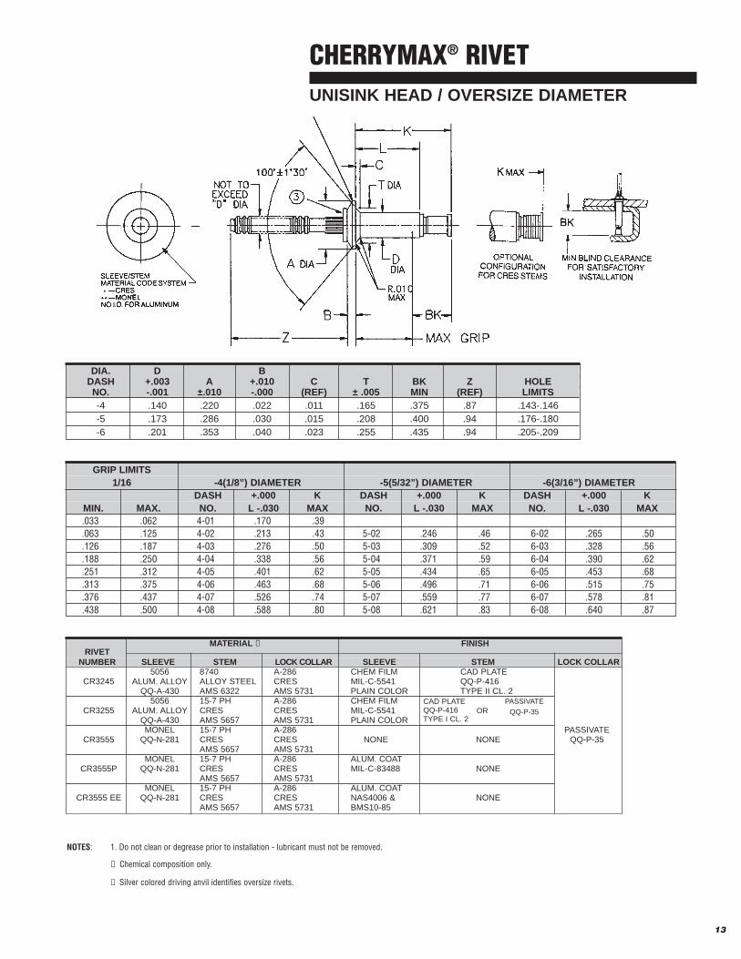
DIA. D BDASH +.003 A +.010 BK Z HOLENO. -.001 ±.010 -.000 MIN (REF) LIMITS-4 .140 .250 .054 .390 .87 .143-.146-5 .173 .312 .067 .395 .94 .176-.180-6 .201 .375 .080 .410 .94 .205-.209-8 .267 .500 .107 .490 .96 .271-.275
CAD PLATEQQ-P-416TYPE I CL. 2
PASSIVATE
QQ-P-35OR
CHERRYMAX® RIVETUNIVERSAL HEAD / OVERSIZE DIAMETER

12
CHERRYMAX® RIVET100° FLUSH HEAD / OVERSIZE DIAMETER
DIA. D CDASH +.003 A ➀ B BK Z HOLENO. -.001 ±.004 (REF) MIN (REF) ALUM MONEL LIMITS-4 .140 .225 .035 .390 .87 .002-.010 .005-.015 .143-.146-5 .173 .286 .047 .395 .94 .002-.012 .005-.015 .176-.180-6 .201 .353 .063 .410 .94 .002-.012 .005-.015 .205-.209-8 .267 .476 .086 .490 .96 .002-.016 .005-.015 .271-.275
MATERIAL ➃ FINISHRIVET
NUMBER SLEEVE STEM LOCK COLLAR SLEEVE STEM LOCK COLLAR5056 8740 A-286 CHEM FILM CAD PLATE
CR3242 ALUM. ALLOY ALLOY STEEL CRES MIL-C-5541 QQ-P-416QQ-A-430 AMS 6322 AMS 5731 PLAIN COLOR TYPE II CL. 2
5056 15-7 PH A-286 CHEM FILMCR3252 ALUM. ALLOY CRES CRES MIL-C-5541
QQ-A-430 AMS 5657 AMS 5731 PLAIN COLORMONEL 15-7 PH A-286 PASSIVATE
CR3552 QQ-N-281 CRES CRES NONE NONE QQ-P-35AMS 5657 AMS 5731
MONEL 15-7 PH A-286 ALUM. COATCR3552P QQ-N-281 CRES CRES MIL-C-83488 NONE
AMS 5657 AMS 5731MONEL 15-7 PH A-286 ALUM. COAT
CR3552EE QQ-N-281 CRES CRES NAS4006 & NONEAMS 5657 AMS 5731 BMS10-85
INCO 600 INCO X-750 A-286CR3852 AMS 5687 AMS 5687 CRES NONE NONE
AMS 5731
CAD PLATEQQ-P-416TYPE I CL. 2
PASSIVATE
QQ-P-35OR
GRIP LIMITS1/16 -4(1/8”) DIAMETER -5(5/32”) DIAMETER -6(3/16”) DIAMETER -8(1/4”) DIAMETER
DASH +.000 K DASH +.000 K DASH +.000 K DASH +.000 KMIN. MAX. NO. L -.030 MAX NO. L -.030 MAX NO. L -.030 MAX NO. L -.030 MAX.045 .062 4-01 .220 .45➁ .125 4-02 .238 .45 5-02 .266 .47 6-02 .265 .48
.126 .187 4-03 .301 .52 5-03 .309 .53 6-03 .328 .55 8-03 .375 .64
.188 .250 4-04 .363 .58 5-04 .371 .60 6-04 .390 .62 8-04 .437 .70
.251 .312 4-05 .426 .65 5-05 .434 .66 6-05 .453 .68 8-05 .500 .77
.313 .375 4-06 .488 .71 5-06 .496 .72 6-06 .515 .74 8-06 .562 .83
.376 .437 4-07 .551 .78 5-07 .559 .79 6-07 .578 .82 8-07 .625 .89
.438 .500 4-08 .613 .84 5-08 .621 .85 6-08 .640 .89 8-08 .687 .95
.501 .562 4-09 .676 .90 5-09 .684 .91 6-09 .703 .95 8-09 .750 1.02
.563 .625 5-10 .746 .98 6-10 .765 1.01 8-10 .812 1.08
.626 .687 5-11 .809 1.04 6-11 .828 1.07 8-11 .875 1.14
.688 .750 5-12 .871 1.10 6-12 .890 1.14 8-12 .937 1.20
.751 .812 6-13 .953 1.20 8-13 1.000 1.27
.813 .875 8-14 1.062 1.60
NOTES: ➀ Head diameters are to theoretical projection.
➁ Minimum grip for: -4 dia. = .063Minimum grip for: -5 dia. = .065Minimum grip for: -6 dia. = .080
3. Do not clean or degrease prior to installation - lubricant must not be removed.
➃ Chemical composition only.
➄ Silver colored driving anvil identifies oversize rivets.
HEAD MARKINGS VISIBLE AFTER INSTALLATION
13
CHERRYMAX® RIVETUNISINK HEAD / OVERSIZE DIAMETER
GRIP LIMITS1/16 -4(1/8”) DIAMETER -5(5/32”) DIAMETER -6(3/16”) DIAMETER
DASH +.000 K DASH +.000 K DASH +.000 KMIN. MAX. NO. L -.030 MAX NO. L -.030 MAX NO. L -.030 MAX.033 .062 4-01 .170 .39.063 .125 4-02 .213 .43 5-02 .246 .46 6-02 .265 .50.126 .187 4-03 .276 .50 5-03 .309 .52 6-03 .328 .56.188 .250 4-04 .338 .56 5-04 .371 .59 6-04 .390 .62.251 .312 4-05 .401 .62 5-05 .434 .65 6-05 .453 .68.313 .375 4-06 .463 .68 5-06 .496 .71 6-06 .515 .75.376 .437 4-07 .526 .74 5-07 .559 .77 6-07 .578 .81.438 .500 4-08 .588 .80 5-08 .621 .83 6-08 .640 .87
MATERIAL ➁ FINISHRIVET
NUMBER SLEEVE STEM LOCK COLLAR SLEEVE STEM LOCK COLLAR5056 8740 A-286 CHEM FILM CAD PLATE
CR3245 ALUM. ALLOY ALLOY STEEL CRES MIL-C-5541 QQ-P-416QQ-A-430 AMS 6322 AMS 5731 PLAIN COLOR TYPE II CL. 2
5056 15-7 PH A-286 CHEM FILMCR3255 ALUM. ALLOY CRES CRES MIL-C-5541
QQ-A-430 AMS 5657 AMS 5731 PLAIN COLORMONEL 15-7 PH A-286 PASSIVATE
CR3555 QQ-N-281 CRES CRES NONE NONE QQ-P-35AMS 5657 AMS 5731
MONEL 15-7 PH A-286 ALUM. COATCR3555P QQ-N-281 CRES CRES MIL-C-83488 NONE
AMS 5657 AMS 5731MONEL 15-7 PH A-286 ALUM. COAT
CR3555 EE QQ-N-281 CRES CRES NAS4006 & NONEAMS 5657 AMS 5731 BMS10-85
CAD PLATEQQ-P-416TYPE I CL. 2
PASSIVATE
QQ-P-35OR
NOTES: 1. Do not clean or degrease prior to installation - lubricant must not be removed.
➁ Chemical composition only.
➂ Silver colored driving anvil identifies oversize rivets.
DIA. D BDASH +.003 A +.010 C T BK Z HOLENO. -.001 ±.010 -.000 (REF) ± .005 MIN (REF) LIMITS-4 .140 .220 .022 .011 .165 .375 .87 .143-.146-5 .173 .286 .030 .015 .208 .400 .94 .176-.180-6 .201 .353 .040 .023 .255 .435 .94 .205-.209

14
CHERRYMAX® RIVET120° FLUSH HEAD / OVERSIZE DIAMETER
GRIP LIMITS1/16 -4(1/8”) DIAMETER -5(5/32”) DIAMETER -6(3/16”) DIAMETER
DASH +.000 K DASH +.000 K DASH +.000 KMIN. MAX. NO. L -.030 MAX NO. L -.030 MAX NO. L -.030 MAX.063 .125 4-02 .238 .45 5-02 .266 .47 6-02 .265 .48.126 .187 4-03 .301 .52 5-03 .309 .53 6-03 .328 .55.188 .250 4-04 .636 .58 5-04 .371 .60 6-04 .390 .62.251 .312 4-05 .426 .65 5-05 .434 .66 6-05 .453 .68.313 .375 4-06 .488 .71 5-06 .496 .72 6-06 .515 .74
MATERIAL ➂ FINISHRIVET
NUMBER SLEEVE STEM LOCK COLLAR SLEEVE STEM LOCK COLLAR5056 8740 A-286 CHEM FILM CAD PLATE
CR3246 ALUM. ALLOY ALLOY STEEL CRES MIL-C-5541 QQ-P-416QQ-A-430 AMS 6322 AMS 5731 PLAIN COLOR TYPE II CL. 2MONEL 15-7 PH A-286
CR3556 QQ-N-281 CRES CRES NONE NONE PASSIVATEAMS 5657 AMS 5731 QQ-P-35
MONEL 15-7 PH A-286 ALUM. COATCR3556P QQ-N-281 CRES CRES MIL-C-83488 NONE
AMS 5657 AMS 5731MONEL 15-7 PH A-286 ALUM. COAT
CR3556EE QQ-N-281 CRES CRES NAS4006 & NONEAMS 5657 AMS 5731 BMS10-85
DIA. D CDASH +.003 A ➀ B BK Z HOLENO. -.001 ±.004 (REF) MIN (REF) ALUM MONEL LIMITS-4 .140 .272 .038 .390 .87 .002-.010 .005-.015 .143-.146-5 .173 .314 .041 .395 .94 .002-.012 .005-.015 .176-.180-6 .201 .350 .048 .410 .94 .002-.012 .005-.015 .205-.209
NOTE: ➀ Head diameters are to theoretical projection.
2. Do not clean or degrease prior to installation - lubricant must not be removed.
➂ Chemical composition only.
➃ Silver colored driving anvil identifies oversize rivets.
HEAD MARKINGS VISIBLE AFTER INSTALLATION

15
DRILLING
Use a clean, sharp, properly ground drill.Improperly ground drills will create oval oroversize holes. Center the drill in thechuck so that the drill will run true. A“wobble” in the drill will create an oversizehole. Hold the drill perpendicular to the surface being drilled. Do not force the drillthrough the material.
DO NOT CHAMFER OR OTHERWISEREMOVE THE SHARP EDGE OFTHE BLIND SIDE OF THE JOINT!
To insure proper hole alignment and toprevent burrs and chips from lodgingbetween the sheets, the materials to beriveted should be clamped tightly together.Hole filing, hollow, pull thru or “tack” rivetsmay be used in conjunction with spring-loaded clamps to prevent material “creep”and hole misalignment during the drilling operation.
CHERRYMAX® RIVET INSTALLATIONX
NOMINAL CHERRYMAXRIVET DRILL HOLE SIZE
DIAMETER SIZE MIN. MAX.
-4 (1/8")0 #30 .129 .132
-5 (5/32") #20 .160 .164
-6 (3/16") #10 .192 .196
-8 (1/4")0 F .256 .261
OVERSIZE CHERRYMAXRIVET DRILL HOLE SIZE
DIAMETER SIZE MIN. MAX.
-4 (1/8")0 #27 .143 .146
-5 (5/32") #16 .176 .180
-6 (3/16") #5 .205 .209
-8 (1/4")0 I .271 .275
DRILL SIZES
Drill sizes shown in table below are those which normally produce holes within the specified limits. To assure drilling
accuracy, holes should be checked with a go-no-go gage asshown on page 6.
SPRINGLOADEDFASTENER
CLEANHOLE “TACK”
RIVET
CHIPSMISALIGNMENT

CHERRYMAX® RIVET COUNTERSINKING & INSTALLATIONX
16
Accurate countersinking is of primary importance to the structural integrity of a flush riveted joint. Standard countersink-ing procedures as used with solid rivets are also applicable toCherryMAX rivets. The following points, however, should benoted:
The countersink pilot should be no more than .001" smallerthan the hole diameter. A greatly undersize pilot will producecountersinks which are not concentric with the hole, creating“cocked” head and head gapping problems.
MS20426 NAS1097 UNISINK RIVET 100° HEAD 100° HEAD 100° HEAD 120° HEAD
DIAMETER C MIN. C MAX. C MIN. C MAX. C MIN. C MAX. C MIN. C MAX.-4 (1/8”)0 .222 .228 .189 .195 .167 .173 .269 .275-5 (5/32”) .283 .289 .240 .246 .210 .216 .311 .317-6 (3/16”) .350 .356 .296 .302 .252 .258 .347 .353-8 (1/4”)0 .473 .479 .389 .395 — — — —
PLACING THE RIVET IN THE HOLE
The holes in the sheets to be fastened must be of the correct size and haveproper alignment. Do not force the rivet into the hole! To aid in achieving properclamp-up of the sheets, use tack rivets and/or spring loaded clamps.
PLACING THE PULLING HEAD ON THE RIVET STEM
Hold the riveter and pulling head in line with the axis of the rivet as shown inthe illustration. Press firmly against the head of the rivet to minimize headgapping and sheet gap. Apply a firm, steady pressure and pull the rivetertrigger to begin installation sequence. The installation cycle will help clampthe sheets together, seat the rivet head, and break the stem flush with thehead of the rivet. After the stem breaks, release the trigger. The pin-tail portion of the stem will be ejected back thru the riveter head. A stem catcherbag may be obtained to collect the pin-tails, Part Number 670A20. See page 25.
WARNING: Operating the riveter with a damaged or missing stem deflector,or using the deflector as a handle, may result in severe personal injury.
B REFERENCERIVET CR3212 CR3214 CR3242 CR3245 CR3246
DIAMETER 100° NOMINAL 100° NAS 1097 100° OVERSIZE 100° OVERSIZE 120° OVERSIZEUNISINK
-4 (1/8”)0 .041 .028 .035 .011 .038-5 (5/32”) .054 .037 .047 .015 .041-6 (3/16”) .069 .046 .063 .023 .048-8 (1/4”)0 .095 .086 .060 — —
RIGHT WRONG
PULLINGHEAD
COMPARISON CHART OF RIVET HEADS “B” FOR CHERRYMAX FLUSH HEAD RIVETS
Material thickness for non-dimpled countersinks should not be
less than rivet head height (‘B’ dimension) plus .010". See table
for ‘B’ dimensions.
RIGHT WRONG MISALIGNEDHOLE
100°
C
.010"R.Max

17
CHERRYMAX® RIVET INSPECTION
AA
B B
Shown is typical installed fastener flushness acceptance criteria. Locking collar is to be flush withthe top surface of the rivet head. Collar flash permissible is .010 max. Stem flushness shall be as indicated.
RIVET DIAMETER. A MAX. B MAX.
-4 (1/8")0 .010” .015”
-5 (5/32") .010” .020”
-6 (6/16") .010” .020”
-8 (1/4")0 .015” .025”
ACCEPTABLE BLIND HEAD FORMATIONS
TYPICALMIN. GRIP
IRREGULARFORMATIONMIN. GRIP
TYPICALMAX. GRIP
A
B
A
B

18
CHERRYMAX® RIVET TOOLING
A Systems Approach to Fasteners and Tooling

19
CHERRYMAX® RIVET TOOLING SELECTION CHARTX
➀ Will not install Monel or Inconel fasteners ➁ Requires use of 744-200 adapter ➂ Requires use of 744-300 adapter➃ Non standard tool
CHERRY PULLINGALL GRIP LENGTHS, HEAD STYLES & MATERIALS EXCEPT AS NOTED
RIVETER HEAD NOMINAL DIAMETER OVERSIZE DIAMETERMODEL NUMBER
-4 -5 -6 -8 -4 -5 -6 -8
G27 INCLUDED
H701B-456 ➂
H753A-456 ➂
H781-456 ➂G83
H84-8 ➀ ➀
H827-8 ➁ ➀ ➀
H828-8 ➁ ➀ ➀
H84-8
H827-8 ➁
H828-8 ➁G84
H701B-456 ➂
H753A-456 ➂
H781-456 ➂
G686B-S H680B200A
H680B200AG689
H680B208
G700 H680B200A ➀
H70IB-456G747
H753A-456G746A
H781-456
G704B H701B-456
G704B-40SH H753A-456
G704B-SR H781-456
H744A-8
G744➃ H827-8
G744-85SH➃ H828-8
H846A-465
INCLUDEDG750A
H750A-8
G784 H680B200A
The tooling and pulling head combinations shown in the chart below
will install the diameter rivets indicated by the shaded areas, in all grip
lengths, and materials, except as noted.
For more information regarding installation tooling combinations,
please contact Technical Service, Textron Fastening Systems,
Santa Ana Operations (714) 850-6022

20
CHERRYMAX® RIVET TOOLING
HAND RIVETERS AND KITS
To obtain optimum advantage of CherryMAX® fasteners, it isrecommended that CherryMAX® tooling be selected to installthose fasteners.
G27
NATIONAL STOCK NUMBER 5120-01-393-1538
The G27 is a light-weight (13 oz) hand tool for use in low production applications such as repair, maintenance or prototype work. The pulling head is an integral part of this riveter.
G750A
NATIONAL STOCK NUMBER 5120-01-432-9361Service Kit Number G750AKS
The Cherry G750A hand hydraulic riveting tool provides the versatility of a pneumatic-hydraulic riveter but with the lightweight, high pull strength ratio not found in other hand riveters. The Cherry G750A has a unique, patentable, 2-stagehydraulic power cylinder that provides the user with the ease ofpulling the handle without the strain normally endured to installa high strength fastener. The Cherry G750A hand riveter caninstall a variety of blind fastener styles, diameters, head configurations, and material combinations. The G750A with thestandard pulling head can install CherryMAX® and SST™ blindrivets in -4, -5, -6, diameters, and -04, -05, -06 diameterMaxiBOLT blind bolts or threaded inserts by simply changingthe pulling head.
G750ACMR
NATIONAL STOCK NUMBER 5120-01-432-6190
The Cherry G750ACMR hydraulic riveter tool kit includes theG750A with an H750A-456 pulling head, and adapter assembly,a right angle pulling head, an offset pulling head and a sturdyplastic carrying case.
➤
➤
➤
➤
➤
➤
.5"(12.7 mm)
2"(50.8 mm)
9.25"(234.9 mm)
➤
➤
➤
➤
➤
➤
6.5"(165.1 mm)
7.75"(196.8 mm)
6.4"(162.5 mm)
1 Ea. G750A Hydraulic Hand Riveter(Includes Pulling Head) 1 Ea. H781-456 Offset Pulling Head 1 Ea. H753A-456 Right Angle Pulling Head 1 Ea. 750A-088 Adapter Assembly 1 Ea. H781-456 Tool Sheet 1 Ea. H753A-456 Tool Sheet
1 Ea. 269C3 Grip Gage1 Ea. TLC816 CherryMAX Process Manual1 Ea. MaxiBolt Reference Card TLC8721 Ea. P1340 Tool Box1 Ea. TLC865 CherryMAX Reference Card
21
CHERRYMAX® RIVET TOOLING
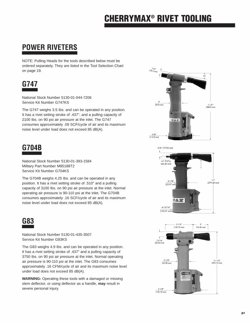
POWER RIVETERS
NOTE: Pulling Heads for the tools described below must beordered separately. They are listed in the Tool Selection Charton page 19.
G747
National Stock Number 5130-01-044-7206Service Kit Number G747KS
The G747 weighs 3.5 Ibs. and can be operated in any position.It has a rivet setting stroke of .437", and a pulling capacity of2100 Ibs. on 90 psi air pressure at the inlet. The G747 consumes approximately .09 SCF/cycle of air and its maximumnoise level under load does not exceed 85 dB(A).
G704B
National Stock Number 5130-01-393-1584 Military Part Number M85188T2Service Kit Number G704KS
The G704B weighs 4.25 Ibs. and can be operated in any position. It has a rivet setting stroke of .510" and a pullingcapacity of 3100 Ibs. on 90 psi air pressure at the inlet. Normaloperating air pressure is 90-110 psi at the inlet. The G704B consumes approximately .16 SCF/cycle of air and its maximumnoise level under load does not exceed 85 dB(A).
G83
National Stock Number 5130-01-435-3507Service Kit Number G83KS
The G83 weighs 4.9 Ibs. and can be operated in any position. It has a rivet setting stroke of .437" and a pulling capacity of3750 Ibs. on 90 psi air pressure at the inlet. Normal operatingair pressure is 90-110 psi at the inlet. The G83 consumesapproximately .16 CFM/cycle of air and its maximum noise levelunder load does not exceed 85 dB(A).
WARNING: Operating these tools with a damaged or missingstem deflector, or using deflector as a handle, may result insevere personal injury.
➤
➤
➤
➤
➤➤
➤
➤
➤
*
2-1/8"(53.97 mm)
3/4" (19.05 mm)
1-3/4"(44.45 mm)
➤ ➤
4-15/16"
(125.41 mm)
11"(279.40 mm)
.719"(18.3 mm)
➤➤2"
(50.8 mm)
➤
➤
➤
➤➤
➤
11.37"(288.8 mm)
10°
4.56"(115.8 mm)
➤
➤
➤
➤
13/16"(20.64 mm)
➤ ➤
➤➤
➤➤2-1/8"
(53.98 mm)
5-1/2"(139.70 mm)
3"(76.20 mm)
➤
➤
11-1/2"(292.10 mm)
5-1/8" ➤
➤
(130.18 mm)

22
SPLIT POWER RIVETERS
G704B-SR
G704B-SR National Stock Number 5130-01-237-0488Service Kit Number G704KS
The G704B-SR Split Riveter is designed specifically for theinstallation of CherryMAX rivets in extremely limited accessapplications. It transmits power from the power unit throughthree feet of flexible hose to a small, lightweight head. By utilizing the appropriate pulling head, design problems andoperator fatigue can be greatly reduced.
The riveters have a rivet setting stroke of .510" and a pullingcapacity of 3100 lbs. on 90 psi air pressure at the air inlet.Normal operating air pressure range is 90–110 psi at the inlet.The maximum noise level under load does not exceed 85dB(A).
Pulling heads must be ordered separately. They are listed,along with the riveter's capacity (same as the G704B), in thetool selection chart on page 19.
G704B-40SH
G704B-40SH National Stock Number 5130-01-374-1335Service Kit Number G704B-40SR/-40SHKS
The G704B-40SH is designed specifically for the easiest andmost efficient installation of CherryMAX rivets. In using these“split” tools, the power unit rests on the floor and transmits itspower through 8 feet of hose to a lightweight pistol-grip handle.This facilitates rivet installation in many limited access areasand also greatly reduces operator fatigue.
The G704B-40SH riveter operates on 90–110 psi of air pressureat the air inlet.
G704B-40SH .510" stroke 3100 lbs. pull
Pulling heads must be ordered separately. They are listed,along with the riveter's capacity, in the tool selection chart onpage 19.
CHERRYMAX® RIVET TOOLING
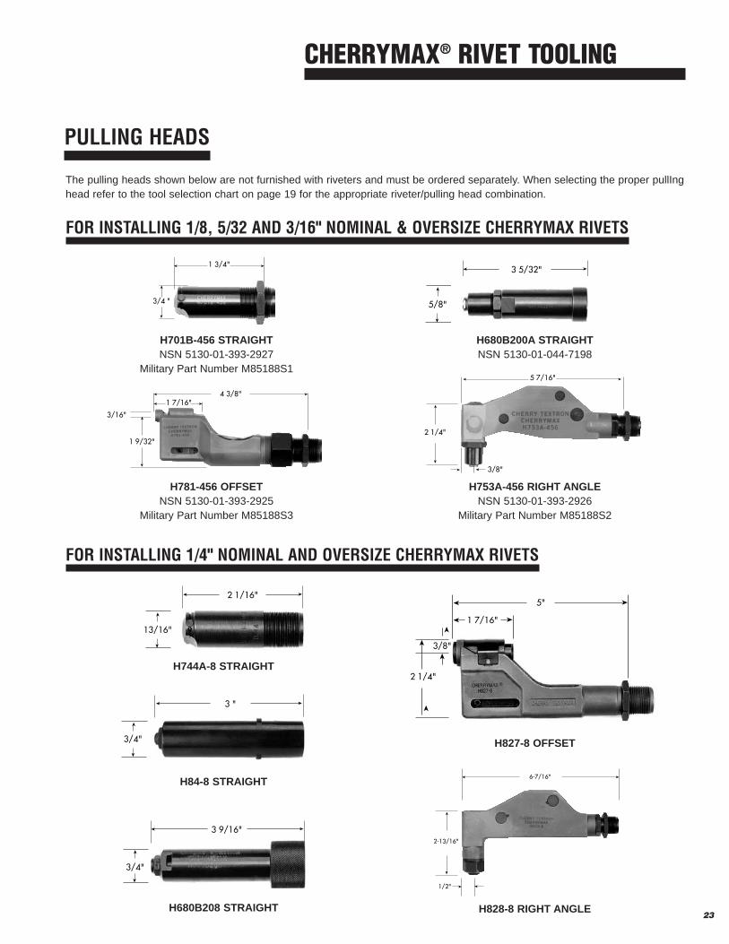
PULLING HEADS
23
CHERRYMAX® RIVET TOOLING
H701B-456 STRAIGHTNSN 5130-01-393-2927
Military Part Number M85188S1
H781-456 OFFSETNSN 5130-01-393-2925
Military Part Number M85188S3
H680B200A STRAIGHTNSN 5130-01-044-7198
H753A-456 RIGHT ANGLENSN 5130-01-393-2926
Military Part Number M85188S2
➤
➤
➤
➤➤
➤5 7/16"
2 1/4"
3/8"
➤➤3 5/32"
➤
➤
5/8"
➤➤
➤ ➤
4 3/8"1 7/16"
➤
➤
1 9/32"
3/16"
➤
➤➤
➤
3/4 "
1 3/4"
FOR INSTALLING 1/8, 5/32 AND 3/16" NOMINAL & OVERSIZE CHERRYMAX RIVETS
H828-8 RIGHT ANGLEH680B208 STRAIGHT
The pulling heads shown below are not furnished with riveters and must be ordered separately. When selecting the proper pullInghead refer to the tool selection chart on page 19 for the appropriate riveter/pulling head combination.
➤
➤➤
➤
➤
➤
➤
➤
1 7/16"
5"
2 1/4"
3/8"
➤
➤
➤
6-7/16"
➤
2-13/16"
1/2"
➤
➤
➤➤2 1/16"
➤
➤
13/16"
➤➤3 "
➤
➤
3/4"
➤➤3 9/16"
➤
➤
3/4"
FOR INSTALLING 1/4" NOMINAL AND OVERSIZE CHERRYMAX RIVETS
H827-8 OFFSET
H84-8 STRAIGHT
H744A-8 STRAIGHT

24
CHERRYMAX® RIVET TOOLING
EXTENSIONS
Combinations of these extensions may be used to reach many restricted installation areas by increasing the overall length of thepulling head.
704A12-2 (2") NSN 5130-01-145-0206704A12-4 (4") NSN 5130-01-145-0207704A12-6 (6") NSN 5130-01-145-0208704A12-12 (12") NSN 5130-01-178-0331
These extensions will fit directly on to the G747, G704B andG746A CherryMAX Riveters and will accept any of the pullingheads listed for those riveters in the Tool Selection Chart onpage 19.
753B21 (1-1/8") (Not Shown)
This extension increases the overall length of the H753A-456right angle pulling head nosepiece to approximately 2-3/16",enabling it to reach into more restricted areas.
ADAPTERS
These adapters fit the G747, G704B and G746A CherryMAX riveters to accept pulling heads designed for the installation of MS-type blind rivets in shorter grip lengths.
704A6 NSN 5130-01-145-6189Permits the use of H9040 snap-on type pulling head.
704A9 NSN 5130-01-134-8231Permits the use of H9015 screw-on type pulling head.

ADAPTERS
These adapters permit various Cherry riveters to accept pulling heads for the installation of CherryMAX rivets that the riveterswere not originally intended to pull.
680B205 NSN 5130-01-175-4015Permits the G686B-S, G689, G700 and G784 to accept theH753A-456 and H781-456 pulling heads for installing 1/8, 5/32and 3/16" CherryMAX rivets.
744-300Permits the G83 and G84 riveters to accept the H701B-456,H753A-456 and H781-456 pulling heads for installing 1/8, 5/32and 3/16" CherryMAX rivets.
744-200Permits the G83 and G84 riveters to accept the H827-8 (offset),and H828-8 (right angle) pulling heads for installing 1/4"
diameter CherryMAX rivets.
ACCESSORIES
701B32 MAGNETIC DRIVING ANVIL CATCHER
The 701B32 magnetic driving anvil catcher provide method tosecurely catch and hold the driving anvil as they fall away afterCherryMAX rivet installation. This anvil catcher slips onto thenose of the pulling head without any need for permanent attachment.
670-037-1 STEM CATCHER BAGNSN 5130-01-154-1141
The 670-037-1 stem catcher bag is a convenient accessorywhich helps eliminate litter from the shop floor. This heavydenim bag equipped with a heavy-duty strap snaps over thestem deflector of the G701 A, G704B, G746A, G747, G83 andG84 CherryMAX riveters to catch the spent stems as they areejected from the rear of the riveter head. Also available: 670A20 catcher bag.
700D107 URETHANE BASE PLATE
The 700D107 Urethane Base Plate replaces the standard aluminum base plate of the G704B, G704B-SR, G747, G746Aand G83 riveters. The urethane base stabilizes the riveter, lightens it, is shock absorbing, and protects finished surfacesfrom marring. The urethane base is impervious to industrial solvents, installs easily, and adds to overall installation tool performance. 25
CHERRYMAX® RIVET TOOLING

© 2003 Textron Fastening Systems Supplier’s Federal Identification Code - 11815 CA-42-5M-1003
Please visit our web site, www.textronfasteningsystems.com/aerospace, for product catalog information or
call our Technical Services Department 714-850-6045 Fax 714-850-6093
Santa Ana Operations1224 East Warner Ave., Box 2157, Santa Ana, CA 92707-0157
(714) 545-5511 FAX (714) 850-6093 www.textronfasteningsystems.com/aerospace
®