chilled water cassettes 2 pipes - · pdf filechilled water cassettes • 2 pipes k 9 og 2t...
TRANSCRIPT

CHILLED WATER CASSETTES• 2 Pipes
K 9 OG 2TK 12 OG 2TK 18 OG 2T
• 4 PipesK 9 OG 4TK 12 OG 4TK 18 OG 4T
ROOM AIR CONDITIONERS
TECHNICAL DATA 00TKOG12

2
SUMMARY
INTRODUCTION ............................................................................................................................................. 3
TECHNICAL SPECIFICATIONS ........................................................................................................................ 4
COOLING PERFORMANCE ............................................................................................................................ 5
HEATING PERFORMANCE ............................................................................................................................. 7
PRESSURE LOSS OF CHILLED WATER CASSETTES .................................................................................... 9
FIELD OF OPERATION ................................................................................................................................... 13
DIMENSIONS .................................................................................................................................................. 14
INSTALLATION ................................................................................................................................................ 16
CONDENSATE PUMP ..................................................................................................................................... 18FILTER
ELECTRIC HEATING ....................................................................................................................................... 19
CONTROLS AND REGULATION ..................................................................................................................... 20
ELECTRIC SPECIFICATIONS .......................................................................................................................... 22
PRODUCT CODE NUMBERSThis manual covers the following basic product
The informations contained in these instructions are subject to modification without prior notice.
Power supply ~ 230 V - 50Hz
2 PIPES
Without valve��������� ��������� ���������
7OG051 008 7OG051 01 2 7OG051 01 6
With valve��������� ��������� ���������
7OG051 009 7OG051 01 3 7OG051 01 7
2 PIPES WITHEL ECTRICHEATING
Without valve����������� ����������� �����������
7OG051 01 0 7OG051 01 4 7OG051 01 8
With valve����������� ����������� �����������
7OG051 01 1 7OG051 01 5 7OG051 01 9
4 PIPES
Without valve������������ ������������ ������������
7OG051 020 7OG051 022 7OG051 024
With valve������������ ������������ ������������
7OG051 021 7OG051 023 7OG051 025
(for units fitted with options, please refer to the maker's plate) :
3
CHILLED WATER CASSETTES
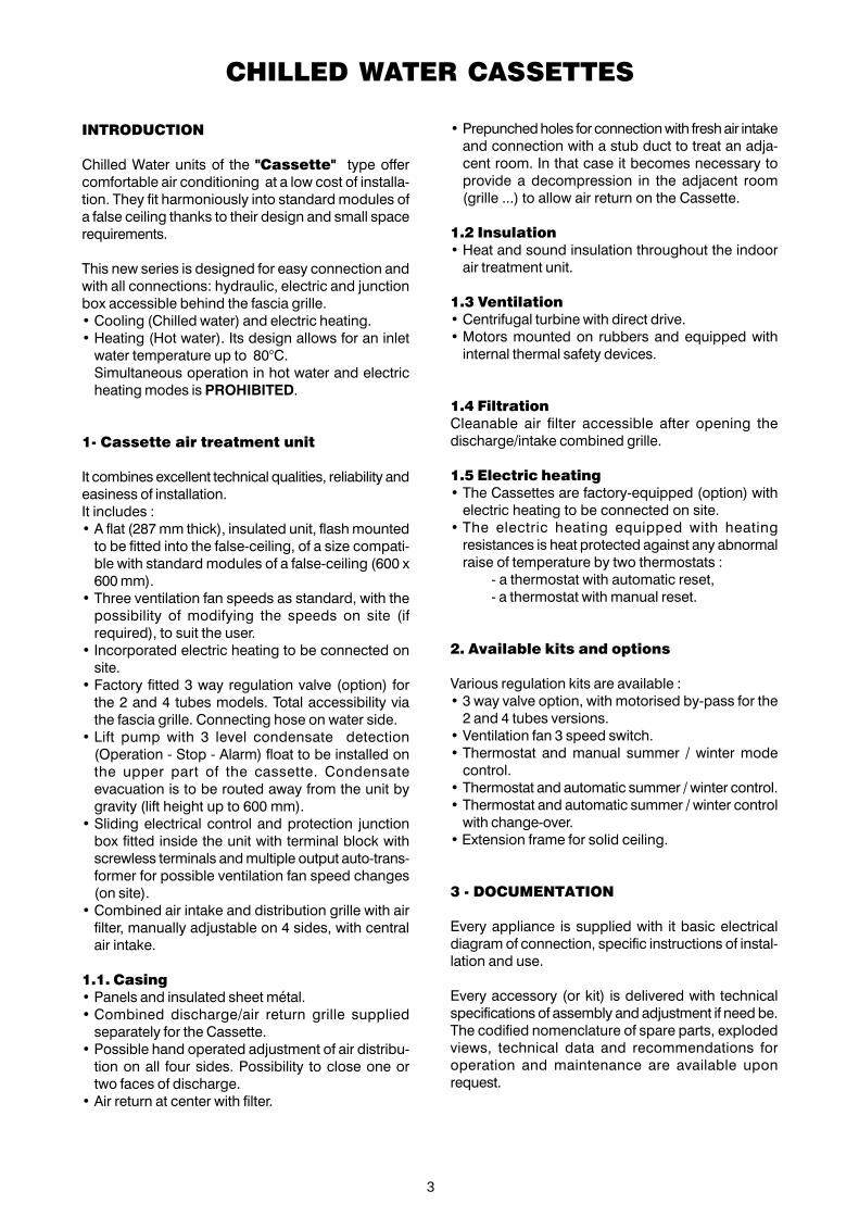
INTRODUCTION
Chilled Water units of the "Cassette" type offercomfortable air conditioning at a low cost of installa-tion. They fit harmoniously into standard modules ofa false ceiling thanks to their design and small spacerequirements.
This new series is designed for easy connection andwith all connections: hydraulic, electric and junctionbox accessible behind the fascia grille.• Cooling (Chilled water) and electric heating.• Heating (Hot water). Its design allows for an inlet
water temperature up to 80°C.Simultaneous operation in hot water and electricheating modes is PROHIBITED.
1- Cassette air treatment unit
It combines excellent technical qualities, reliability andeasiness of installation.It includes :• A flat (287 mm thick), insulated unit, flash mounted
to be fitted into the false-ceiling, of a size compati-ble with standard modules of a false-ceiling (600 x600 mm).
• Three ventilation fan speeds as standard, with thepossibility of modifying the speeds on site (ifrequired), to suit the user.
• Incorporated electric heating to be connected onsite.
• Factory fitted 3 way regulation valve (option) forthe 2 and 4 tubes models. Total accessibility viathe fascia grille. Connecting hose on water side.
• Lift pump with 3 level condensate detection(Operation - Stop - Alarm) float to be installed onthe upper part of the cassette. Condensateevacuation is to be routed away from the unit bygravity (lift height up to 600 mm).
• Sliding electrical control and protection junctionbox fitted inside the unit with terminal block withscrewless terminals and multiple output auto-trans-former for possible ventilation fan speed changes(on site).
• Combined air intake and distribution grille with airfilter, manually adjustable on 4 sides, with centralair intake.
1.1. Casing• Panels and insulated sheet métal.• Combined discharge/air return grille supplied
separately for the Cassette.• Possible hand operated adjustment of air distribu-
tion on all four sides. Possibility to close one ortwo faces of discharge.
• Air return at center with filter.
• Prepunched holes for connection with fresh air intakeand connection with a stub duct to treat an adja-cent room. In that case it becomes necessary toprovide a decompression in the adjacent room(grille ...) to allow air return on the Cassette.
1.2 Insulation• Heat and sound insulation throughout the indoor
air treatment unit.
1.3 Ventilation• Centrifugal turbine with direct drive.• Motors mounted on rubbers and equipped with
internal thermal safety devices.
1.4 FiltrationCleanable air filter accessible after opening thedischarge/intake combined grille.
1.5 Electric heating• The Cassettes are factory-equipped (option) with
electric heating to be connected on site.• The electric heating equipped with heating
resistances is heat protected against any abnormalraise of temperature by two thermostats :
- a thermostat with automatic reset,- a thermostat with manual reset.
2. Available kits and options
Various regulation kits are available :• 3 way valve option, with motorised by-pass for the
2 and 4 tubes versions.• Ventilation fan 3 speed switch.• Thermostat and manual summer / winter mode
control.• Thermostat and automatic summer / winter control.• Thermostat and automatic summer / winter control
with change-over.• Extension frame for solid ceiling.
3 - DOCUMENTATION
Every appliance is supplied with it basic electricaldiagram of connection, specific instructions of instal-lation and use.
Every accessory (or kit) is delivered with technicalspecifications of assembly and adjustment if need be.The codified nomenclature of spare parts, explodedviews, technical data and recommendations foroperation and maintenance are available uponrequest.

4
TECHNICAL SPECIFICATIONS
Chilled water TH 3409
NOTE :1) Nominal conditions :
- Air : 27°C/19°C wetbulb (nominal HS airflow).- Chilled Water : 7°C/12°C.
2) Nominal conditions:- Air : 20°C (Nominal HS airflow).- Hot Water : Te water 50°C
(nominal waterflow in hot water mode).3) Nominal conditions:
- Air : 20°C (Nominal HS airflow).- Hot Water : Te water 70°C Ts water 60°C
4) Pressure loss by corresponding nominal flowThese characreristics are for information only and are subject to change without advance notice.
������������ ������� �������
2 Pipes 4 Pipes 2 Pipes 4 Pipes 2 Pipes 4 Pipes
Nominal cooling capacity ( 1 )W 2200 2200 3500 3430 5000 4900
Nominal supply voltage 230V/50Hz BTU/HR 7500 7500 1 2000 1 1 700 1 7050 1 6700
Nominal heating capacity 2 pipes (2)Nominal heating capacity 4 pipes (3)
W3300
--
22004600
--
32005900
--
4900
Nominal supply voltage 230V/50Hz BTU/HR 1 1 250 7500 1 5700 1 1 000 201 00 1 6700
Air flow (average values)Treated air– High speed– Medium speed– L ow speed– Super low speed
m³/hm³/hm³/hm³/h
700460420
-
700460420
-
700460420
-
700460420
-
76051 5460320
76051 5460320
Nominal water flow (average values) m³/h 0,378 0,378 0,602 0,590 0,860 0,843
Pressure loss on water (4) kPa 1 2 1 2 1 7,5 1 7 1 5 1 7,5
Nominal power supplyVoltage range V
~ 230 V - 50 Hz207 / 253
Power input ventilation(GV) W 60 80 1 1 0
Sound level– High speed– Medium speed– L ow speed– Super low speed
dBAdBAdBAdBA
503734-
503734-
57484239
Dimensions– Air treatment unit ST (W x D x H)– Grille (W x D x H)
mmmm
571 x 571 x 287625 x 625 x 40
Net weight kg 26 26 30
Packing– Gross weight– Packed volume
kgm³
260,1 5
270,1 5
280,1 5
290,1 5
���������������������
– Electric heating • • •
– Motorized 3-way valve with by-pass– 3 speed switch ventilation– Thermostat and reversing switch :manualautomatic
••
••
••
••
••
••

5
COOLING PERFORMANCEChilled Water feeding
MODELS 2 PIPES
Water flow inlet temperature air
������ ������� �������
Nominal air (m³/h) Nominal air (m³/h) Nominal air (m³/h)
����
�����
�� ��
����
�����
�� ��
���!�
�����
��"�"
�� ��
6/1 1 C
27 C50%
PTPS
kW1 ,801 ,36
1 ,931 ,45
2,431 ,87
2,631 ,89
2,802,03
3,852,84
2,731 ,85
3,652,56
4,1 02,85
5,604,00
25 C50%
PTPS
kW1 ,561 ,21
1 ,631 ,28
2,061 ,65
2,261 ,68
2,401 ,80
3,272,51
2,341 ,65
3,1 52,27
3,482,52
4,803,56
23 C50%
PTPS
kW1 ,201 ,05
1 ,261 ,1 1
1 ,611 ,55
1 ,721 ,45
1 ,871 ,57
2,532,1 9
1 ,841 ,44
2,451 ,97
2,712,1 9
3,743,09
7/1 2 C
27 C50%
PTPS
kW1 ,651 ,29
1 ,741 ,37
2,201 ,77
2,391 ,79
2,561 ,93
3,502,70
2,491 ,76
3,372,43
3,742,70
5,003,78
25 C50%
PTPS
kW1 ,371 ,1 3
1 ,451 ,20
1 ,831 ,56
1 ,991 ,56
2,1 61 ,70
2,912,37
2,091 ,54
2,822,1 3
3,1 22,37
4,273,33
23 C50%
PTPS
kW1 ,010,97
1 ,071 ,03
1 ,361 ,35
1 ,481 ,34
1 ,581 ,44
2,1 52,01
1 ,571 ,32
2,1 51 ,83
2,382,04
3,262,87
8/1 3 C
27 C50%
PTPS
kW1 ,471 ,22
1 ,561 ,30
1 ,951 ,68
2,1 51 ,69
2,291 ,82
3,1 02,54
2,241 ,65
3,022,28
3,342,53
4,543,56
25 C50%
PTPS
kW1 ,1 81 ,05
1 ,251 ,1 2
1 ,581 ,46
1 ,731 ,46
1 ,831 ,57
2,522,21
1 ,831 ,43
2,461 ,98
2,722,20
3,733,1 0
23 C50%
PTPS
kW0,880,88
0,930,93
1 ,211 ,21
1 ,281 ,24
1 ,381 ,33
1 ,891 ,87
1 ,351 ,22
1 ,861 ,70
2,051 ,89
2,832,66
1 0/1 5 C
27 C50%
PTPS
kW1 ,091 ,07
1 ,1 51 ,1 4
1 ,451 ,45
1 ,611 ,47
1 ,741 ,59
2,362,22
1 ,721 ,44
2,321 ,99
2,572,22
3,533,1 4
25 C50%
PTPS
kW0,890,89
0,940,94
1 ,221 ,22
1 ,271 ,25
1 ,371 ,35
1 ,891 ,89
1 ,341 ,23
1 ,841 ,71
2,061 ,91
2,822,69
23 C50%
PTPS
kW0,720,72
0,770,77
1 ,001 ,00
1 ,011 ,01
1 ,1 21 ,1 0
1 ,551 ,55
1 ,031 ,03
1 ,421 ,42
1 ,581 ,58
2,242,24
PT = Total cooling capacity (kW)PS = Sensible cooling capacity (kW)
TH 3410 Chilled water

6
COOLING PERFORMANCEChilled Water feeding
MODELS 4 PIPES
PT = Total cooling capacity (kW)PS = Sensible cooling capacity (kW)
Water flow Inlet temperature air
������ ������� �������
Nominal air (m³/h) Nominal air (m³/h) Nominal ai (m³/h)
����
�����
�� ��
����
�����
�� ��
���!�
�����
��"�"
�� ��
6/1 1 C
27 C50%
PTPS
kW1 ,801 ,36
1 ,931 ,45
2,431 ,87
2,571 ,85
2,772,00
3,792,80
2,711 ,85
3,652,55
4,002,81
5,383,90
25 C50%
PTPS
kW1 ,561 ,21
1 ,631 ,28
2,061 ,65
2,1 91 ,64
2,361 ,76
3,242,48
2,301 ,64
3,1 02,25
3,402,49
4,603,46
23 C50%
PTPS
kW1 ,201 ,05
1 ,261 ,1 1
1 ,611 ,55
1 ,691 ,42
1 ,821 ,53
2,512,1 6
1 ,781 ,41
2,451 ,96
2,632,1 5
3,563,00
7/1 2 C
27 C50%
PTPS
kW1 ,651 ,29
1 ,741 ,37
2,201 ,77
2,341 ,76
2,511 ,90
3,432,65
2,461 ,75
3,302,40
3,662,68
4,903,70
25 C50%
PTPS
kW1 ,371 ,1 3
1 ,451 ,20
1 ,831 ,56
1 ,951 ,52
2,091 ,65
2,882,33
2,051 ,53
2,751 ,1 0
3,032,33
4,013,21
23 C50%
PTPS
kW1 ,010,97
1 ,071 ,03
1 ,361 ,35
1 ,431 ,30
1 ,551 ,42
2,1 41 ,99
1 ,561 ,31
2,1 01 ,82
2,312,01
3,1 32,80
8/1 3 C
27 C50%
PTPS
kW1 ,471 ,22
1 ,561 ,30
1 ,951 ,68
2,091 ,65
2,241 ,78
3,062,50
2,201 ,64
2,952,26
3,242,50
4,313,46
25 C50%
PTPS
kW1 ,1 81 ,05
1 ,251 ,1 2
1 ,581 ,46
1 ,691 ,43
1 ,831 ,55
2,482,1 7
1 ,791 ,42
2,451 ,96
2,642,1 6
3,563,02
23 C50%
PTPS
kW0,880,88
0,930,93
1 ,211 ,21
1 ,251 ,21
1 ,351 ,31
1 ,871 ,84
1 ,301 ,20
1 ,811 ,68
1 ,991 ,86
2,722,59
1 0/1 5 C
27 C50%
PTPS
kW1 ,091 ,07
1 ,1 51 ,1 4
1 ,451 ,45
1 ,561 ,43
1 ,681 ,54
2,312,1 8
1 ,691 ,43
2,291 ,99
2,512,1 9
3,363,06
25 C50%
PTPS
kW0,890,89
0,940,94
1 ,221 ,22
1 ,251 ,22
1 ,351 ,32
1 ,851 ,85
1 ,301 ,21
1 ,811 ,70
1 ,991 ,88
2,702,61
23 C50%
PTPS
kW0,720,72
0,770,77
1 ,001 ,00
0,990,99
1 ,071 ,07
1 ,511 ,51
1 ,001 ,00
1 ,391 ,39
1 ,561 ,56
2,1 52,1 5
Chilled water TH 3411

7
HEATING PERFORMANCE
MODELS 2 PIPES
Water flow Inlet temperature air
������ ������� �������
Nominal air (m³/h) Nominal air (m³/h) Nominal air (m³/h)
����
�����
�� ��
����
�����
�� ��
���!�
�����
��"�"
�� ��
80/60 C
1 9 C PC kW 4,36 4,67 6,37 5,83 6,28 8,68 5,72 7,69 8,40 1 1 ,02
20 C PC kW 4,27 4,56 6,23 5,72 6,1 4 8,50 5,62 7,53 8,23 1 0,81
21 C PC kW 4,1 8 4,48 6,09 5,61 6,02 8,32 5,49 7,37 8,06 1 0,58
70/60 C
1 9 C PC kW 4,06 4,35 5,92 5,37 5,78 8,03 5,1 4 6,95 7,64 1 0,1 0
20 C PC kW 3,97 4,25 5,80 5,25 5,65 7,84 5,03 6,81 7,47 9,89
21 C PC kW 3,88 4,1 5 5,67 5,1 4 5,52 7,66 4,93 6,67 7,31 9,67
50/40 C
1 9 C PC kW 2,1 8 2,33 3,20 2,94 3,1 4 4,37 2,88 3,86 4,22 5,52
20 C PC kW 2,09 2,24 3,07 2,83 3,02 4,1 8 2,77 3,72 4,05 5,30
21 C PC kW 2,01 2,1 3 2,94 2,70 2,91 3,99 2,65 3,55 3,87 5,07
TH 3412 Chilled water

8
HEATING PERFORMANCE
MODELS 4 PIPES
Water flow Inlet temperature air
������ ������� �������
Nominal air (m³/h) Nominal air (m³/h) Nominal air (m³/h)
����
�����
�� ��
����
�����
�� ��
���!�
�����
��"�"
�� ��
80/60 C
1 9 C PC kW 1 ,88 2,01 2,26 2,57 2,70 3,42 2,92 3,77 4,09 5,29
20 C PC kW 1 ,84 1 ,98 2,23 2,51 2,63 3,34 2,85 3,68 4,00 5,1 8
21 C PC kW 1 ,78 1 ,92 2,1 7 2,45 2,45 3,27 2,79 3,60 3,92 5,05
70/60 C
1 9 C PC kW 1 ,84 1 ,93 2,25 2,46 2,59 3,28 2,76 3,56 3,87 5,02
20 C PC kW 1 ,80 1 ,90 2,20 2,40 2,50 3,20 2,70 3,48 3,70 4,90
21 C PC kW 1 ,76 1 ,83 2,1 4 2,33 2,47 3,1 3 2,63 3,40 3,69 4,79
50/40 C
1 9 C PC kW 0,89 0,92 1 ,09 1 ,26 1 ,33 1 ,68 1 ,46 1 ,87 2,02 2,61
20 C PC kW 0,84 0,88 1 ,04 1 ,21 1 ,28 1 ,60 1 ,39 1 ,79 1 ,93 2,51
21 C PC kW 0,80 0,83 0,97 1 ,1 5 1 ,21 1 ,52 1 ,33 1 ,70 1 ,85 2,40
Chilled water TH 3413

9
��#���$�����%&&������
Twm ( C)\% Glycol �� � !� �� "�
3 1 ,1 35 1 ,234 1 ,385 1 ,53 1 ,85
5 1 ,1 3 1 ,23 1 ,38 1 ,51 1 ,77
1 0 1 ,1 2 1 ,22 1 ,37 1 ,47 1 ,66
1 5 1 ,1 1 1 ,1 9 1 ,36 1 ,46 1 ,64
20 1 ,1 1 ,1 8 1 ,35 1 ,44 1 ,59
25 1 ,09 1 ,1 7 1 ,33 1 ,43 1 ,57
30 1 ,08 1 ,1 6 1 ,31 1 ,42 1 ,56
35 1 ,07 1 ,1 5 1 ,29 1 ,41 1 ,54
40 1 ,06 1 ,1 4 1 ,28 1 ,4 1 ,52
45 1 ,05 1 ,1 3 1 ,25 1 ,37 1 ,49
50 1 ,04 1 ,1 2 1 ,22 1 ,34 1 ,47
55 0,99 1 ,1 1 ,2 1 ,31 1 ,44
60 0,94 1 ,09 1 ,1 9 1 ,28 1 ,42
PRESSURE LOSS OF CHILLED WATER CASSETTES
DPwo : Pressure loss of pure waterDPw : Pressure loss of brinewater∆Pw = K x ∆Pwo
Twm : Average temperature of the mixture
Tse : Outdoor dry temperature around the water chiller
K 9 OG2 layers - 2 circuits
TH 3414 Chilled water
����������� ��� �� �� �� �� ��
– 25 yes
– 20 yes yes
– 1 5 yes yes
– 1 0 yes yes yes
– 5 yes yes yes yes
0 yes yes yes yes yes
5 yes yes yes yes yes
Pressure drop with valve
Pressure drop without valve
0
10
20
30
40
50
100 200 300 400 500 600
l/h
KP
a
FROIDCOLD
CIRCUITCHAUD 4 TUBESHEAT 4 PIPES
HEAT4 PIPES
COOL2 of 4 PIPES

10
PRESSURE LOSS OF CHILLED WATER CASSETTES
K 12 OG2 layers - 3 circuits
Chilled water TH 3415
Pressure drop with valve
Pressure drop without valve
0
10
20
30
40
50
100 200 300 400 500 600 700
l/h
KP
a
,
CIRCUITCHAUD 4 TUBESHEAT 4 PIPES
FROCOLD
HEAT4 PIPES
COOL2 of 4 PIPES

11
PRESSURE LOSS OF CHILLED WATER CASSETTES
K 18 OG3 layers - 4 circuits
TH 3416 Chilled water
Pressure drop with valve
Pressure drop without valve
0
10
20
30
40
50
300 400 500 600 700 800 900 1000 1100 1200
l/h
KP
a
,

12
PRESSURE LOSS OF CHILLED WATER CASSETTES
K 18 OG 4Tcold water circuit
Pressure drop with valve
Pressure drop without valve
Chilled water TH 3417
0
10
20
30
40
50
60
70
100 200 300 400 500 600 700 800 900 1000
l/ h
KP
a
Circuit chaud
Circuit froid
Heat circuit
Cool circuit

13
FIELD OF OPERATION
MAXIMUM TEMPERATURE
MINIMUM TEMPERATURE
Thi = Indoor wet bulbTsi = Indoor dry bulbTwe = Water temperature at inlet
1- USING CHILLED WATER
2. USING HOT WATER(Electric heating forbidden)
3. CHARACTERISTICS
TH 3418 Chilled water
INDOOR TEMPERATURE CThi 1 3
Tsi 1 7
COOL ING WATER C Twe 3
INDDOR TEMPERATURE CThi 1 3
Tsi 32
COOL ING WATER C Tse 1 8
INDOOR TEMPERATURE CThi 22
Tsi 32
WATER TEMPERATURE AT INL ET MAXI. C Twe 80
������ ������� �������
Contents l 1 ,3 1 ,3 2
Max. pressure of operations bar 1 5 1 5 1 5
Testing pressure bar 24 24 24
2 Pipes couplingsØ 1 /2" gas male 1 /2" gas male 3/4" gas male
mm 1 5-21 male 1 5-21 male 20-27 male
4 Pipes couplingsØ 1 /2" gas male 1 /2" gas mâle
1 /2" gas male (heat)3/4" gas male ( cool)
mm 1 5-21 male 1 5-21 male1 5-21 male20-27 male

14
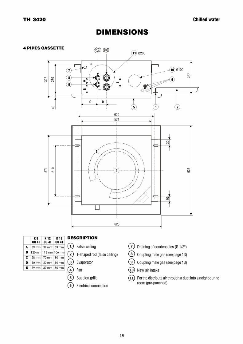
DIMENSIONS
2 PIPES CASSETTE
Chilled water TH 3419
�������
�������
�������
39 mm 39 mm 50 mm
1 20 mm 1 1 3 mm 95 mm
� 1 1 8 mm 1 20 mm 1 02 mm
10
11
1
2
3
4
5
6
7
8
9
DESCRIPTION
False ceiling
T-shaped rod (false ceiling)
Evaporator
Fan
Succion grille
Electrical connection
Ø200
Ø100
327
270
40
287
620
571
625
571
510
625
30
30
1
10
11
3
4
6
2
7
8
9
5
C
AB
Draining of condensates (Ø 1/2")
Coupling male gas (see page 13)
Coupling male gas (see page 13)
New air intake
Port to distribute air through a duct into a neighbouringroom (pre-punched)
15
DIMENSIONS
Ø200
Ø100
32
7
27
04
0
28
7
620
571
625
57
1
51
0
62
5
30
30
1
10
11
3
4
6
2
7
8
9
5
C D
E
AB
��������
��������
��������
39 mm 39 mm 39 mm
1 20 mm 1 1 3 mm 1 06 mm
� 28 mm 70 mm 80 mm
� 50 mm 50 mm 50 mm
39 mm 39 mm 50 mm
TH 3420 Chilled water
4 PIPES CASSETTE
10
11
1
2
3
4
5
6
7
8
9
DESCRIPTION
False ceiling
T-shaped rod (false ceiling)
Evaporator
Fan
Succion grille
Electrical connection
Draining of condensates (Ø 1/2")
Coupling male gas (see page 13)
Coupling male gas (see page 13)
New air intake
Port to distribute air through a duct into a neighbouringroom (pre-punched)

16
INSTALLATION
Eau glacée TH 3421
See specifications of assembly in the installation instructions supplied with the appliance.
Indoor unitThe Air Treatment Units is to be flush - mounted into a false ceiling of standard 600 x 600 mm modules.Fastening is carried out with threaded rods to be fixed on clamps which are supplied.
Distribution of treated airPlace the Air Treatment Unit in the center of the room to allow air to be distributed on all four faces of theappliance.it is possible to close the discharge on 1 or 2 faces in order to adapt the air distribution to the constraints of theroom to be treated.
Air distribution at dischargeThe louvers of air discharge of the treatment unit can be set in three different, clearly defined positions
Fresh air intake and treated air discharge towards an adjacent roomPrepunched openings at the side allow to install ducts to intake fresh air from the outside or to dischargetowards an adjacent room.
FRESH AIR INTAKEFresh air flow should not exceed 12% of nominal air flow (See table hereunder).An anti-fost thermostat preset at + 5°C, installed on site on fresh air intake is mandatory for winter application.A filter, fan and insulated air duct (not supplied) are to be installed on site.
Fresh air intake (Ø 100)
Air discharge in adjacent room (Ø 200)

17
INSTALLATION
Treated air discharge in an adjacent roomIn case of discharge towards an adjacent room, provide for decompression toward the air return of the treatmentunit.
1 CLOSED AIR LOUVER
Dischargeduct
Avai
labl
e st
atic
pre
ssur
eAv
aila
ble
stat
ic p
ress
ure
Dischargeduct
2 CLOSED AIR LOUVERS
TH 3422 Chilled water
18
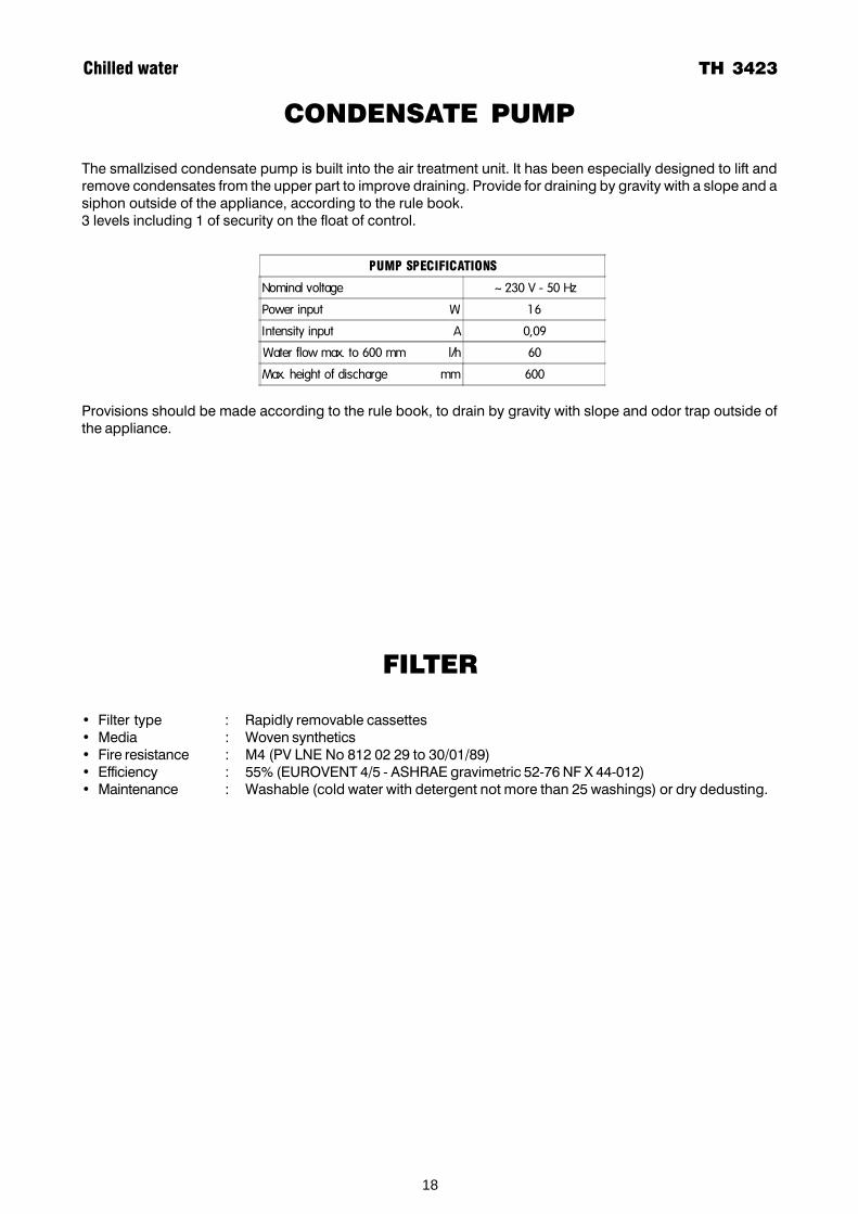
CONDENSATE PUMP
The smallzised condensate pump is built into the air treatment unit. It has been especially designed to lift andremove condensates from the upper part to improve draining. Provide for draining by gravity with a slope and asiphon outside of the appliance, according to the rule book.3 levels including 1 of security on the float of control.
Provisions should be made according to the rule book, to drain by gravity with slope and odor trap outside ofthe appliance.
�'�����(�)*)���)�+�
Nominal voltage ~ 230 V - 50 Hz
Power input W 1 6
Intensity input A 0,09
Water flow max. to 600 mm l/h 60
Max. height of discharge mm 600
FILTER
• Filter type : Rapidly removable cassettes• Media : Woven synthetics• Fire resistance : M4 (PV LNE No 812 02 29 to 30/01/89)• Efficiency : 55% (EUROVENT 4/5 - ASHRAE gravimetric 52-76 NF X 44-012)• Maintenance : Washable (cold water with detergent not more than 25 washings) or dry dedusting.
Chilled water TH 3423

19
ELECTRIC HEATING
TH 3424 Chilled water
��,��,���-����� �������
������ 1 500 W
������� 2250 W
������� 2600 W
The electric heating of the cassettes is composed of heating resistances placed inside the pipes of theevaporator. These resistances are heat protected against any abnormal temperature rise by two thermostatsequipped with a "positive safety" device (mechanical or thermic destruction of the capillary switches off theheating permanently) :
• a thermostat with automatic reset,• a thermostat with manual reset.
ELECTRIC HEATING CAPACITY
Power supply : ~230 V - 50 Hz

20
CONTROLS AND REGULATION
Chilled water TH 3425
2 PIPES AND 4 PIPES REGULATIONGeneral diagram.Manufacturing changes can lead to modifications. Always refer to the diagram supplied with the product.
PC009
PC004/1
PC008Heat
Cold
Neutral
MV Fan motorMP Pump motorCV CondenserTV Fan motor transformerPCB Printed circuit boardSB1 Pump operation water level detectorSB2 Water level Warning level detectorYF 3 way valveYC Heat walve (4 pipes)R1/R2 Electric heating resistancesKH Electric heating relaysFCA Automatic safety thermostatFCM Manuel reset thermal safety deviceX Terminal blockQ1 ProtectionSW Pipe of thermostat
SPEEDS :Terminal 3 : LowTerminal 4 : MediumTerminal 5 : High
~230 V - 50 Hz
PC009• On/Off• 3 fan speeds• independent control
PC008• On/Off• 3 fan speeds• Automatic thermostat on
electric heating / Chilledwater (2 pipes)
• Hot water / Chilled water(4 pipes)
PC004/1• On/Off• 3 fan speeds• Thermostat• Manual heating / cooling change
over on heating resistances andcooling valve (2 pipes)or2 valves (4 pipes)
BK blackBN brownBU blueGNYE green/yellowGY greyOG orangeRD redVT violetWH white
PCB
TAKE CARE : This wiring diagram is correct at the time of publication. manufacturingchanges can lead to modifications. Always refer to the diagram supplied with theproduct.

21
CONTROLS AND REGULATION
TH 3426 Chilled water
REGULATION 2 PIPES + CHANGE-OVERGeneral diagram.Manufacturing changes can lead to modifications. Always refer to the diagram supplied with the product.
PC008Heat
Cold
Neutral
~230 V - 50 Hz
Option N1 Valve 3 ways• On/Off• 3 fan speeds• Automatic thermostat
andTube thermostat on water circuit- heating in winter- chilled in summer
• Power supplied to :SW and terminals 8 and 9
Option N2 Valve 3 ways and electrical heating• On/Off• 3 fan speeds• Automatic thermostat
andTube thermostat on water circuit- heating in winter- chilled in summeror electric resistances during the mid seasons
• Power supplied to :SW and terminals 8 and 9
PCB
TAKE CARE : This wiring diagram is correct at the time of publication. manufacturing changes can lead to modifications. Always refer to thediagram supplied with the product.
BK blackBN brownBU blueGNYE green/yellowGY greyOG orangeRD redVT violetWH white
MV Fan motorMP Pump motorCV CondenserTV Fan motor transformerPCB Printed circuit boardSB1 Pump operation water level detectorSB2 Water level Warning level detectorYF 3 way valveYC Heat walve (4 pipes)R1/R2 Electric heating resistancesKH Electric heating relaysFCA Automatic safety thermostatFCM Manuel reset thermal safety deviceX Terminal blockQ1 ProtectionSW Pipe of thermostat
SPEEDS :Terminal 3 : LowTerminal 4 : MediumTerminal 5 : High
22
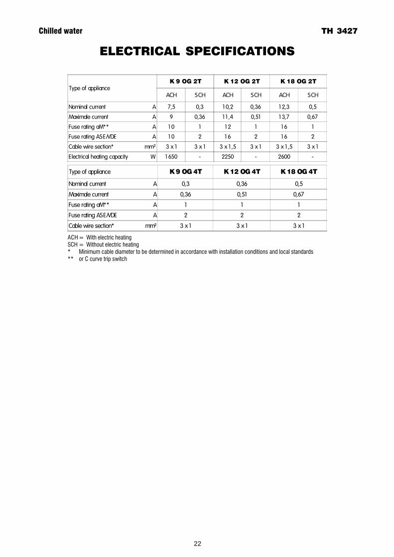
ELECTRICAL SPECIFICATIONS
Chilled water TH 3427
ACH = With electric heatingSCH = Without electric heating* Minimum cable diameter to be determined in accordance with installation conditions and local standards** or C curve trip switch
Type of appliance��������� ���������� ����������
ACH SCH ACH SCH ACH SCH
Nominal current A 7,5 0,3 1 0,2 0,36 1 2,3 0,5
Maximale current A 9 0,36 1 1 ,4 0,51 1 3,7 0,67
Fuse rating aM** A 1 0 1 1 2 1 1 6 1
Fuse rating ASE/VDE A 1 0 2 1 6 2 1 6 2
Cable wire section* mm² 3 x 1 3 x 1 3 x 1 ,5 3 x 1 3 x 1 ,5 3 x 1
Electrical heating capacity W 1 650 - 2250 - 2600 -
Type of appliance ��������� ���������� ����������
Nominal current A 0,3 0,36 0,5
Maximale current A 0,36 0,51 0,67
Fuse rating aM** A 1 1 1
Fuse rating ASE/VDE A 2 2 2
Cable wire section* mm² 3 x 1 3 x 1 3 x 1

A.C.EFRANCE :1 bis,Avenue du 8 Mai 1945Saint-Quentin-en-Yvelines78284 GUYANCOURT Cedex Tél. 33 1 39 44 78 00 Fax 33 1 39 44 11 55 www.airwell.com
ACE Klimatechnik GmbHDEUTSCHLAND :Berner Straße 4360437 FRANKFURT/MAIN Tel. 0 69/507 02-0 Fax 0 69/507 02-250 www.airwell.de
Itelco-Clima SrlITALY :Via Montefeltro 420156 MILANO Tel. 02. 334.219.1 Fax 02.334.219.33 www.itelco-clima.com
Iber elco s.a.SPAIN :Ciències 71-81Mòdul 5POLIGONO PEDROSA08908 L'HOSPITALET DE LLOBREGAT Tel.34-93-335 04 44 Fax 34-93-335 95 38 www.iberelco.es