chimney fundamentals and operation the art of venting flue gases or how not to kill your client...
TRANSCRIPT

Chimney FundamentalsAnd Operation
The Art of Venting Flue GasesOrHow Not To Kill Your Client
Presenter: Earl Hicks

Objectives Review New York WAP policy regarding venting
systems BPI Standards Review combustion process Define & understand combustion air How does a vent system work Identify venting categories and materials Using venting rules-of-thumb Inspection of existing flues Alternative venting methods
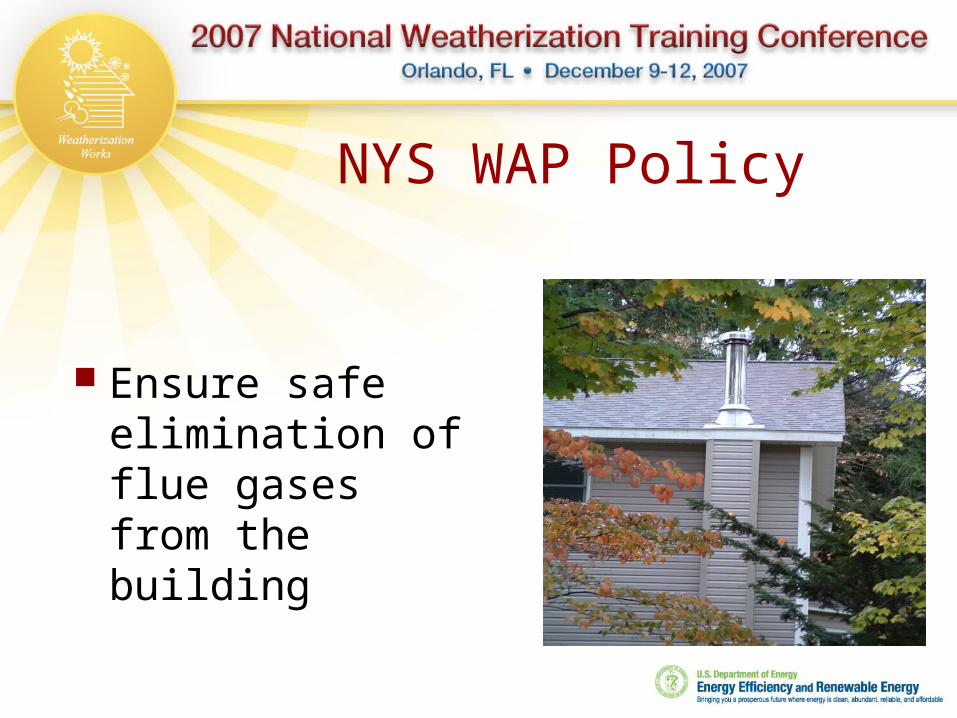
NYS WAP Policy
Ensure safe elimination of flue gases from the building
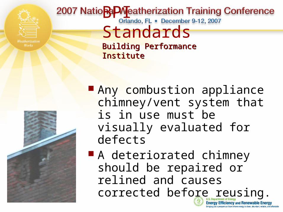
BPI StandardsBuilding Performance Building Performance InstituteInstitute
Any combustion appliance chimney/vent system that is in use must be visually evaluated for defects
A deteriorated chimney should be repaired or relined and causes corrected before reusing.

Principles Of Combustion
Three essential components for combustion Fuel Oxygen Heat
Fuel – Fossil fuels Oxygen – Air is 20.9% O2
Heat – Pilot, spark, or igniter

Combustion Principles

The Chemical Reaction
CH4 + 4O2 + heat = CO2 + 2H2O + heat Complete combustion Natural gas
1 Cu Ft of CH4 + 10 Cu Ft of air for complete combustion
11 Cu Ft of flue gases

Combustion Air
Must supply sufficient air for complete combustion when all appliances are in operation simultaneously.
Must determine whether CAZ is a confined or unconfined space per NFPA.
Tightening a dwelling too much may result in the need to bring in outside air for combustion regardless of NFPA classification.
Must follow established standards for bringing in combustion air.


Confined / Unconfined
Confined Space Not enough air in the combustion appliance
zone to provide for complete combustion when all appliances are operating and the building is set in worst case criteria.
Unconfined Space Enough air is present to provide for
complete combustion when all combustion appliances are operating and the house is set for worst case criteria.

Standard 1/20 Rule
Measure the volume of the CAZ. Add all input Btu ratings of appliance in the CAZ. If dryer is in CAZ
Electric – consider input rate of 100,000 Gas – consider input rate of 125,000
Divide this total Btu by 20. The resulting number is the Cu. Ft. separating
confined from unconfined space. Volume of CAZ below result = confined space Volume of CAZ above result = unconfined space
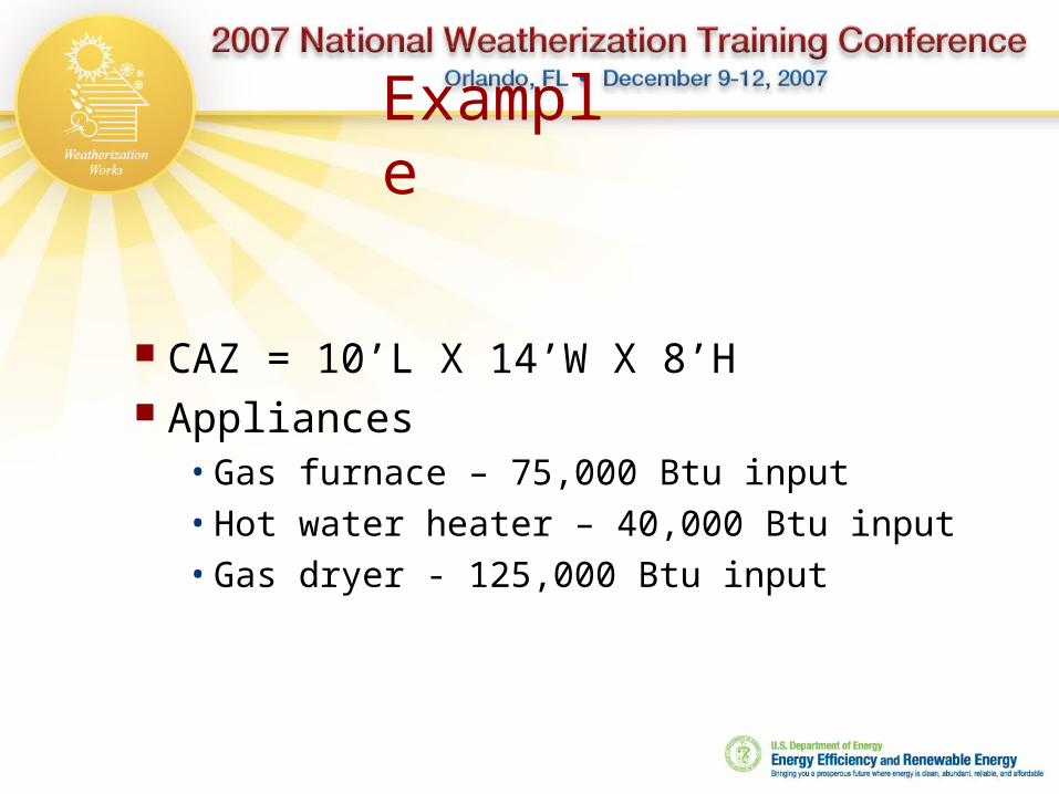
Example
CAZ = 10’L X 14’W X 8’H Appliances• Gas furnace – 75,000 Btu input• Hot water heater – 40,000 Btu input• Gas dryer - 125,000 Btu input
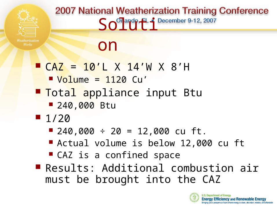
Solution
CAZ = 10’L X 14’W X 8’H Volume = 1120 Cu’
Total appliance input Btu 240,000 Btu
1/20 240,000 ÷ 20 = 12,000 cu ft. Actual volume is below 12,000 cu ft CAZ is a confined space
Results: Additional combustion air must be brought into the CAZ

Other Than Standard:
IMPORTANT! The above standard is based on a known infiltration rate of less than .4 air changes per hour
When the ACH is known For appliances other than fan-assisted,
consult NFPA 54 8.3.2.2(1) For fan-assisted appliances, consult
NFPA 54 8.3.2.2(2)

Table9.3.2.2(a)NaturalDraftAppliances

Table 9.3.2.2(b)Fan Assisted Appliances

Methods of Bringing In Combustion Air
Within the dwelling, from other zones Ducted in horizontally from OD Directly from OD above and or below

What is Draft
Negative pressure within a flue that pulls products of combustion out from the dwelling.

Factors That Affect Draft Pressure
Delta T, Indoors to Outdoors Height of Vent Interior Volume Restrictions Atmospheric Conditions Pressure Imbalances in the CAZ

How Does A VentingSystem Work?
Combustion Gases
Air Flow

What is Considered Adequate Draft?
OD temp >800F, >-1 Pa or - .005”WC OD temp 300 – 800F, >-2.5 Pa or -.01”WC OD temp below 300F, >-5 Pa or -.02”WC
(250 pascal = 1”W.C.)
Most Common Poor Draft Factors Found in the Field
Return air leaks in the basement Long horizontal vent connectors Blocked vents
Deteriorated flue Bird nests
Outside masonry flues with fan assisted heating appliances
Fireplaces with no outside combustion air and without front enclosures.
Overly tight houses

VENTING CATEGORIES

Venting Categories
NFPA 54 and 58 criteria Standardized
Category I• Negative pressure, non-
condensing Category II
• Negative Pressure, condensing• No longer produced
Category III• Positive pressure, non-condensing
Category IV• Positive pressure, condensing
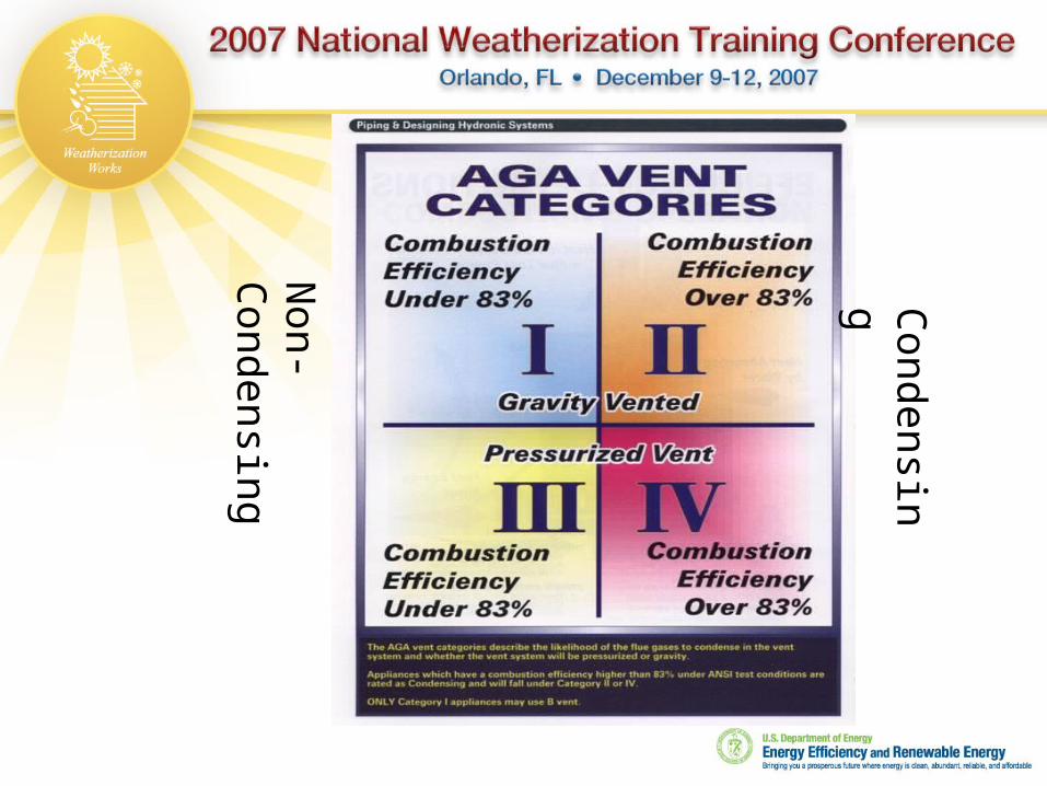
Non-
Condensing
Condensing

Category I
What we normally think of when we think chimney
Negative pressure sucks products of combustion from the appliance breech and deposits them outdoors
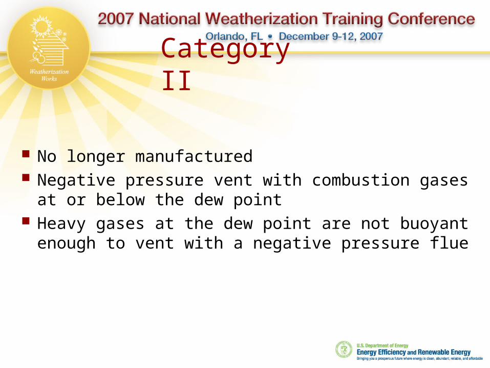
Category II
No longer manufactured Negative pressure vent with combustion
gases at or below the dew point Heavy gases at the dew point are not buoyant
enough to vent with a negative pressure flue

Category III Direct sidewall vented without additional
apparatus. Positive pressure requires joints in flue material
to be sealed Because these 80% appliance flue gases are
close to the dew point, and the vent material is single wall, corrosion resistant materials must be used
Drains are typically incorporated to remove flue condensation before it enters the heat exchanger

Category III
Has been used to solve installation problems where no appropriate flue is available
Positive pressure requires joints in flue material to be sealed


Category IV Positive pressure condensing
appliances, joints must be sealed 90%+ AFUE Appliances are designed to dispose
of flue condensate as well as condensate formed within the secondary heat exchanger
May be able to sidewall vent at reduced distances to openings in the building than NFPA suggests Sealed combustion Combustion air intake in same pressure
plane

Category I Vent MaterialsFound With Older Heating Appliances
Category I Vent MaterialsFound With Older Heating Appliances
Single wall galvanized pipe, 26 gauge Only as a connector on 70% AFUE and
lower gas appliances and all oil appliances Connector for oil appliances
Masonry Vitreous clay liner Oil appliances
Transite Rated as single wall Asbestos Does not meet any venting requirements

“B” Vent – double wall Galvanized steel outside, aluminum
inner pipe Rated only for gas appliances Used as a vent connector for all 78%
and 80% AFUE appliances May not be run outside of the building Used as a liner in an existing flue chase
Category I Vent Materials
cont.
Category I Vent Materials
cont.

Flexible liner Aluminum – gas appliances Stainless Steel – gas and oil appliances Used to retrofit existing flue passages to meet code or a
specific application “L” Vent – double wall
Inner and outer pipes are stainless steel Oil appliances
All Fuel, double wall insulated Oil Solid Fuels
Category I Vent Materials
cont.
Category I Vent Materials
cont.

Category III Flue Materials
Aluminum No longer recommended because of corrosion problems
Stainless Steel Use type specified by manufacturers to reduce corrosion
issues High temperature plastic
Was the most common material specified by manufacturers Have been involved in recall Manufacturer specific installation protocol
• Sealed joints, High temperature sealant• Hanger spacing• Pitch back to appliance ¼” per Ft.
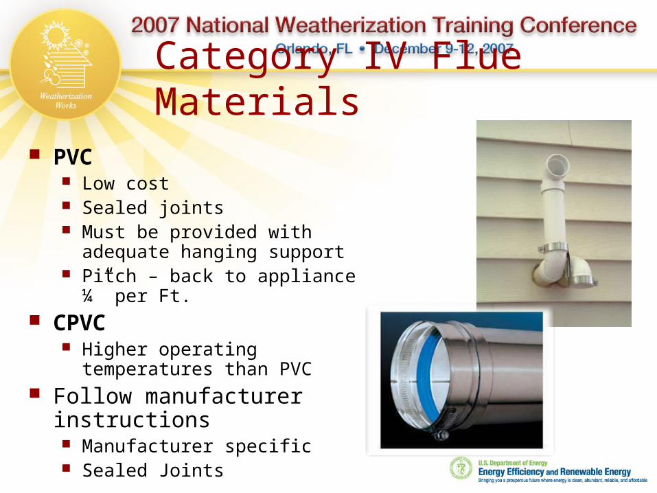
Category IV Flue Materials
PVC Low cost Sealed joints Must be provided with
adequate hanging support Pitch – back to appliance ¼”
per Ft. CPVC
Higher operating temperatures than PVC
Follow manufacturer instructions Manufacturer specific Sealed Joints

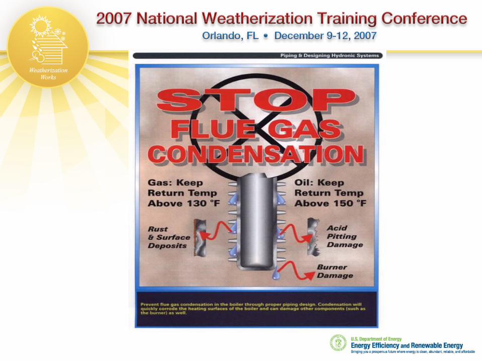
Water In The Flue
Water is a byproduct of combustion Key for category I appliances is to
maintain water in a gaseous state within the flue so that it exits to the outdoors.
Category IV appliances are engineered to remove liquid water from within the secondary heat exchanger and flue.


• 93#(lbs) ~ 10 gallons
•Million Btu = 100,000 Btu @ 10 Hrs run time
•10 Hr run time for natural gas = 10 gallons of water that must be removed from the flue.

70% AFUE Gas Furnace Overview
21 Cu Ft flue gases for every 1 Cu Ft of natural gas burned Draft diverter mixes the extra ~10 Cu Ft of air
with the flue gases before entering the flue Reduced efficiency means more heat going
up the chimney, hot flue gases (4500 – 6000F) Dilution gases reduce the relative humidity
and increases the dew point

Draft Hood Appliances
1 Cu Ft CH4 + 10 Cu Ft air + 10 Cu Ft of dilution air mixed at draft hood
21 Cu Ft of flue gases up chimney under maximized conditions
Draft hood aids in minimizing
fluctuation of draft Prevents backdraft from
affecting burner
Spill Switch

78% & 80% AFUE Furnace Venting Overview
Draft induced fan does not force flue gasses into the vent.
A category I flue of adequate design must be used
More heat in the building and less up the chimney yields a colder chimney
Cycle time is longer than older furnaces to adequately warm the flue and keep moisture in a gaseous state.

TO WARM UP A CHIMNEY If firing rate = 100,000 Btu/hr and SSE = 75%, then 75,000
Btu/hr go to the distribution system and 25,000 Btu/hr go through the vent.
If the burner on-cycle is 12 minutes (.2 hrs), then during one cycle the vent receives: .2 hr x 25,000 Btu/hr = 5,000 Btu/cycle MASONRY CHIMNEY:A masonry chimney (block or brick + tile liner) requires about 4570 Btu/.ft. to go from 0o to 120o. So, on a very cold day, about one foot of chimney will be warmed in one burner cycle: 5,000 Btu/cycle @4,570Btu/ft = 1 ft/cycle TYPE B-VENT CHIMNEY:A 6" B-vent chimney requires about 90 Btu/.ft. to go from 0o to 120o. So,5,000 Btu/cycle @ 90Btu/ft = 55 ft/cycle

After Weatherization with aNew Furnace:
If firing rate = 75,000 Btu/hr and SSE =82%, then 61,500 Btu/hr go to the distribution system and 13,500 Btu/hr go through the vent.
If the burner on-cycle is 6 minutes (.1hrs), then during one cycle the vent receives:
.1hr x 13,500 Btu/hr =1,350 Btu/cycle
EXISTING MASONRY CHIMNEY:
About four inches of the existing masonry chimney will be warmed during one burner cycle:
1,350 Btu/cycle @ 4,570Btu/ft = .3 ft/cycle
TYPE B-VENT CHIMNEY:
During each burner on cycle, enough heat to warm 15feet of B vent goes into the chimney:
1,350 Btu/cycle @ 90Btu/ft = 15 ft/cycle
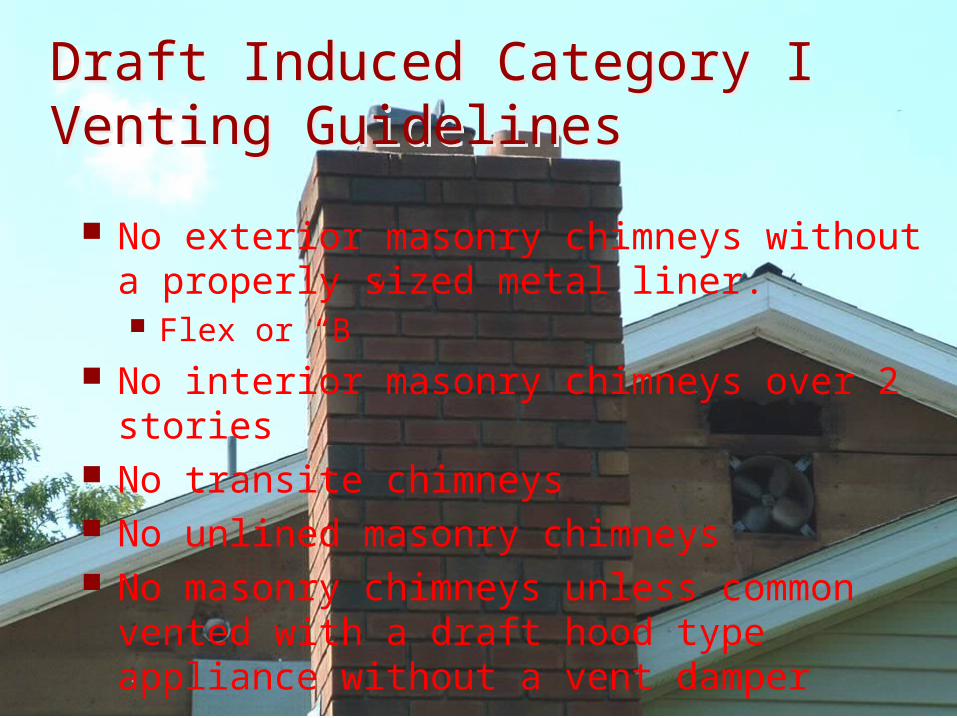
Draft Induced Category I Venting GuidelinesDraft Induced Category I Venting Guidelines
No exterior masonry chimneys without a properly sized metal liner. Flex or “B”
No interior masonry chimneys over 2 stories
No transite chimneys No unlined masonry chimneys No masonry chimneys unless common
vented with a draft hood type appliance without a vent damper

Draft Induced Category I Venting Guidelines (cont.)
Must have double wall “B” vent connector Furnace must be properly sized Furnace must be set up correctly
Temperature rise Gas input Heat anticipator or cycle rate set @ 3 cycles per hour
Vent sizing should be in accordance with tables supplied with the furnace or NFPA
When sidewall venting a power vent kit must be used unless the manufacturer specifies otherwise.

New Category I Venting Rules-Of-Thumb
Use “B” vent as connector from the appliance to the flue Reduce heat loss in the
connector Pitch connector down
toward appliance ¼” per Ft. Warm air rises
Maximum horizontal distance (Table 13.2.2) 1 ½ times the diameter of
the connector in feet 4” connector = 6’
maximum horizontal distance

Rule-Of-Thumb Continued
Follow NFPA 54 sizing charts Never used unlined masonry flue Don’t use outside masonry flue Never use Transite If you take the heating appliance out of the
flue and leave the water heater in, you are responsible to ensure the water heater will vent properly Line the flue

Oil Appliance Venting
NFPA 31 sizing guidelines Masonry Type “L”
stainless steel All fuel

What We Should See In The Field
“L” Vent“L” Vent
“B” Vent“B” Vent
Outside MasonryOutside Masonry

Barometric damper (“swinging door”) in an oil-fired warm air furnace vent.
Drill test hole between the breech and the barometric damper
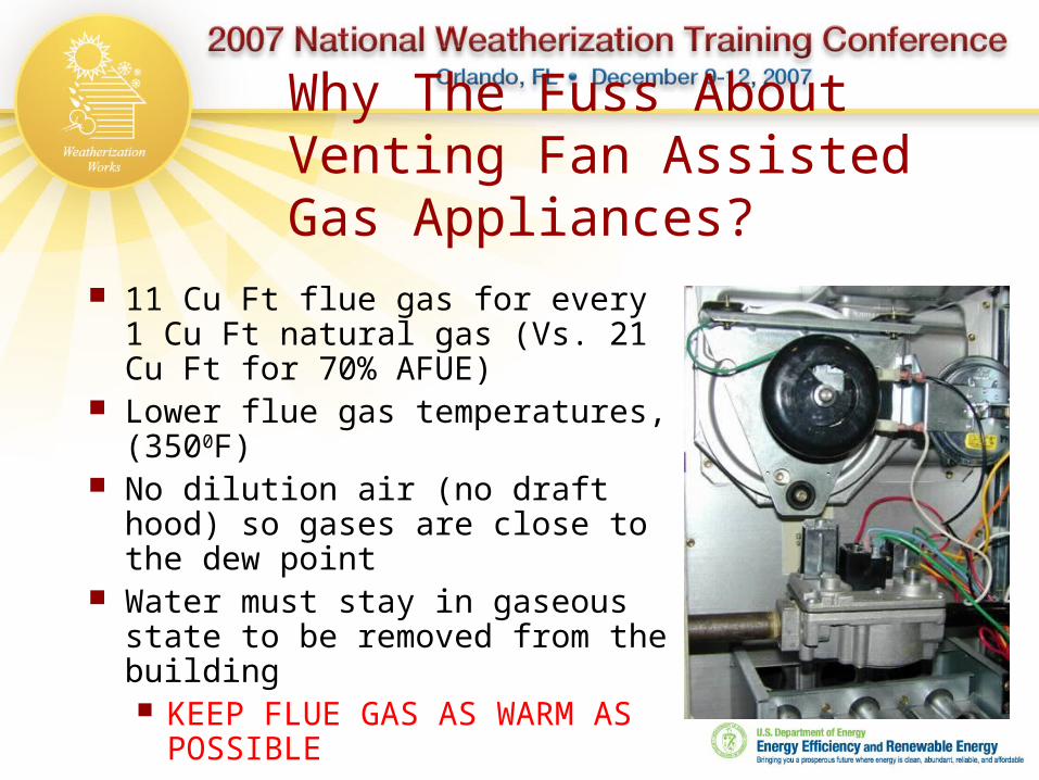
Why The Fuss About Venting Fan Assisted Gas Appliances?
11 Cu Ft flue gas for every 1 Cu Ft natural gas (Vs. 21 Cu Ft for 70% AFUE)
Lower flue gas temperatures, (3500F)
No dilution air (no draft hood) so gases are close to the dew point
Water must stay in gaseous state to be removed from the building KEEP FLUE GAS AS WARM AS
POSSIBLE

Tools & Equipment Used for Vent Inspection & Sizing
NFPA manual 54, Natural Gas 58, LP Gas 31, Oil 211, Solid Fuels
Tape measure Flashlight Mirror Combustion
Analyzer Pressure Probe Temperature Probe
Boroscope Digital Cameral

Safety Inspection of the Venting System
Inside visual inspection General Safety Inspection Vent connections Internal flue inspection
Outside visual inspection CAZ Test

Flue Safety Flue Safety Clearance to combustibles
6” single wall pipe, gas 9” single wall pipe, oil 1” “B” vent, gas Single wall connectors must
not pass through walls. Spill switches Flue blockage Condition of flue materials Draft under worst case
conditions
Combustible?
Fire stop?
1” Clearance?

Vent Connections
Corrosion
Pitch

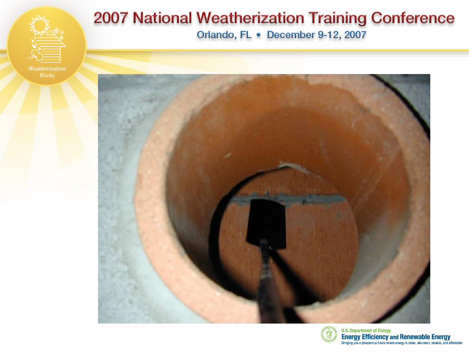
Inspecting An Existing Application
Remove vent connector Inspect with mirror & light
Is the vent straight or is there an offset Is there a liner present Are tiles cracked allowing flue gas to escape Blockage
Examine termination from outside Cap Condition of flue

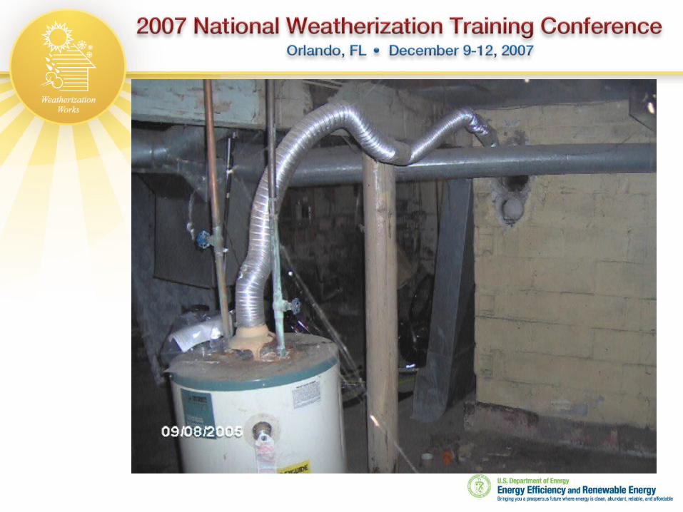
An appliance that produces soot is a cause for concern.
Auditor should call for clean and service.

Evidence of backdrafting

Unsafe vent

Check the chimney for accumulated debris.
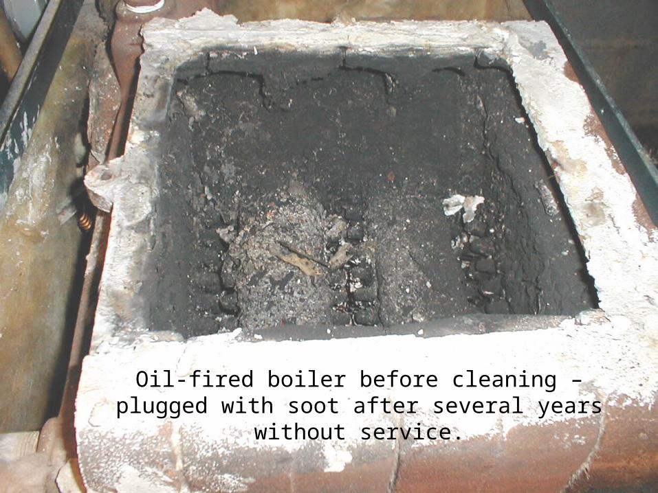
Oil-fired boiler before cleaning – plugged with soot after several years without service.

Same boiler after cleaning


TransiteTransite
Connector
Must be Supported at Base
Must be Supported at Base

Termination Failure

B-vent exposed to the outdoors & not properly supported
Does not meet code (13.2.20) Sizing tables 13.6
through 13.10 are not to be used for “B” vent exposed to the outdoors below the roofline.

Condensation bleed through
Draft assisted furnace, or only water heater left in flue?

Condensation Damage

CAZ Test Place building in winter mode Place all combustion appliances in pilot mode, or
turn off Energize all exhaust fans Measure pressure difference between CAZ in
relation to outdoors Open and close interior doors until the worst case draft
condition is reached Must have draft to continue
OD temp >800F, >-1 Pa or - .005”WC OD temp 300 – 800F, >-2.5 Pa or -.01”WC OD temp below 300F, >-5 Pa or -.02”WC

Vent Dampers
Used to reduce off cycle losses
Motorized End switch safety
Thermal
Spill Switch

Thermal Vent DamperThermal Vent Damper
Bimetal petals warp open when heated


Vent Terminations Follow
manufacturer instructions
Use NFPA guidelines if manufacturer instructions are not available

Category I Chimney termination:
A chimney shall extend at least 3 ft. above the highest point where it passes through a roof of a building and at least 2 ft. higher than any portion of a building within a horizontal distance of 10 ft.
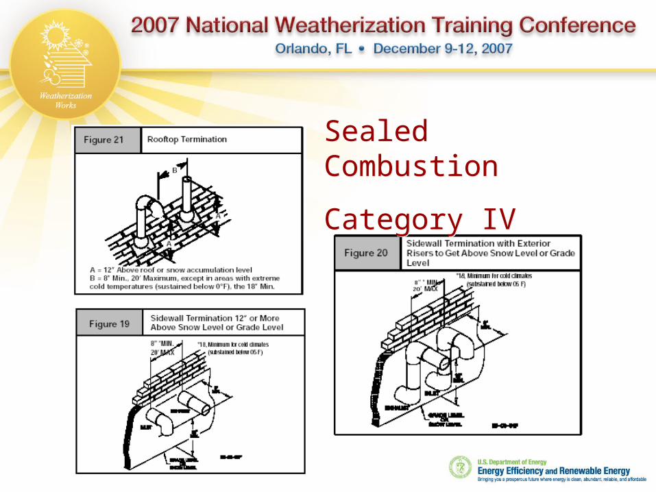
Sealed Combustion
Category IV
Sealed Combustion
Category IV
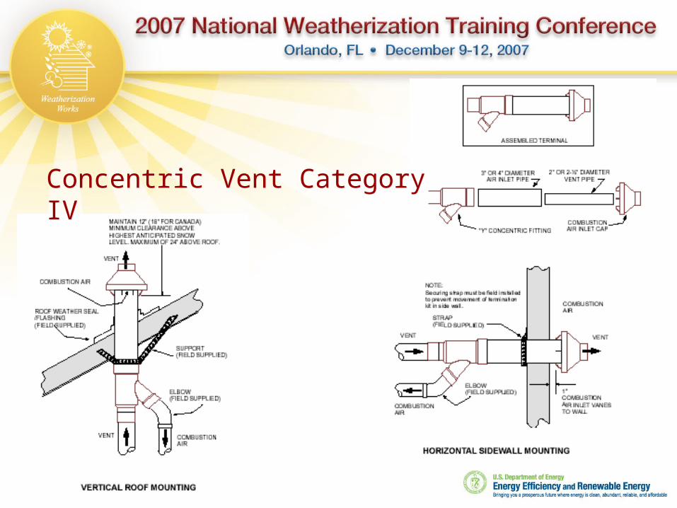
Concentric Vent Category IVConcentric Vent Category IV

Alternative Venting

Look for conditions that may affect health or safety of the occupants, the weatherization crew, and YOU.
Dangerous vent, fire hazards, CO, fuel leaks, etc.
Complete a Health and Safety Warning form if necessary.

Scary, home-made distribution system

REALLY scary homemade vent connector


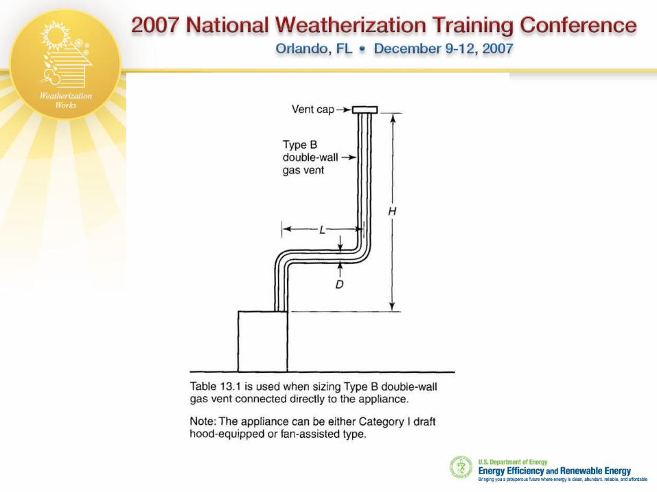
Sizing Category I Vents Use the appropriate NFPA manual
54 for Natural gas 58 for LP for Oil 211 for Solid fuels
Find the appropriate chart One or more appliances? “B” Vent or masonry? “B” Connector or single wall?

Using NFPA Sizing Charts
Height of flue From top of tallest appliance to the top of the flue
termination Increasing the height increases the draw
Horizontal distance to flue Used with single appliance application Increased horizontal run decreases draw
Vertical connector height From the appliance breech to the point where flue gases
combine Used with multiple appliances
Elbows – Charts are listed with up to (2) 900 elbows in the vent


Problem #1
Single draft assisted appliance
50,000 BTU input rate Total chimney height = 17’ Lateral distance = 3’ “B” vent and connector

Problem #2
2 category I appliances 50,000 BTU fan assisted furnace• Connector rise = 2’
30,000 BTU water heater• Connector rise = 3’
“B” vent with “B” connectors Chimney height = 18’


Flexible Flue Liner Follow manufacturer sizing
tables Use NFPA sizing tables, but
reduce capacity by 20% The masonry or original
flue is used as a chase for the liner If a liner is installed, the
remaining space around the liner can not be used to vent other appliances.
More than one liner may be installed in the masonry chase

Other Liner Materials
“B” vent may be used as a liner Drop down an
inadequate or improperly sized flue
Original flue must be straight.
SS flexible liner

1. The height of a chimney is identified as:2. If the chimney height falls between two
columns in the NFPA chart, do you round up or down?
3. For a single category I appliance installation, if the lateral distance falls between two value on the chart, do you round up or down?
4. Can you use NFPA charts to size a flexible chimney liner?
5. What is one advantage of using a flexible liner over “B” vent?
ReviewReview

Vent Free Heaters
NYS WAP Policy Operational Requirements Oxygen Depletion Sensor

NYS WAP Policy
WAP funds cannot be used to purchase or install any type of unvented or ventless combustion appliance including but not limited to unvented kerosene space heaters, unvented natural gas space heaters, unvented propane space heaters, unvented gas fireplaces, and unvented gas fireplace logs.

IAQ / Health & Safety Tests
Unvented Space Heaters: Educate the client about the potential danger of CO and fire from unvented space heaters. Explain that significant amounts of combustion products including water vapor and CO2 are produced.

Combustion Air
Must supply combustion air while operating Open window while operating Tucson instructions require defining the space as
confined / unconfined
Products of combustion remain in the conditioned space
Must provide some measure of safety for oxygen depletion

Fresh Air Requirements
Tucson Heater

Oxygen Depletion Sensor

If You Take Away Nothing Else
KEEP THE WATER IN A GASEOUS STATE WHILE IN THE FLUE
Use “B”vent connectors on any new category I gas appliance installation
Most masonry chimney’s will need a liner Never leave a water heater in a flue alone
without ensuring it will vent