chip washer - department of computer science, …mren/projects/aer201.pdf · this report thoroughly...
TRANSCRIPT

0
CHIP WASHER
Prepared by
Team 40 – Tuesday
Tianyu Li (99107149)
Mengye Ren (998905430)
Yuxiang Zhao
Prepared for
Prof. M.R. Emami
A technical report submitted for
AER201 – Engineering Design

1
ACKNOWLEDGEMENT Our team would like to acknowledge Professor M.R.Emami and Rene Rail-Ip for providing
assistance, suggestions and evaluation for the entire course of machine design and
manufacturing.
Sincerest thanks to Ping Gu for the space for sharing his own condo as the construction site with
us. Thanks to Ping and Joanna Gu, and their neighbours, for enduring the loud noises we made
during countless nights and early mornings.
Grateful appreciation to parents of the members for their emotional and financial support of the
project.
Special thanks to Shawn Fan, April Wang, Ivan Fu, Chauncy Liu, and Annie Cai for their technical
insights and spirit of working through the project.

2
ABSTRACT This report thoroughly introduces Chip washer, a machine prototype in response to the RFP
request [1] from a game company of packing backgammon chips into containers with patterns.
The problem consists of sorting the chips of different colours, loading the chips into containers,
covering the lid of the container, and counting the remaining chips in the machine. Chip washer
is able to provide a solution to the problem satisfactorily.
Chip washer is not only designed for the basic tasks described in the RFP. Many extra features
are added to the machine without violating any of the constraints. In the end, chip washer is
proven to pack at least two times as many chips and containers. No circuit was burnt during
debugging and system integration, which is a powerful indicator of the machine safety. Strong
software component of chip washer provides user greatest customizability and convenience.
Extra features of the software include customizable patterns, machine logs, and PC interface.
The machine did not fully perform the designated task in the competition, due to the
breakdown of the base motor ten minutes ago before the demonstration. Qualified runs were
recorded consistently before the demonstration. The failure of demonstration indicates the lack
of accuracy and the wrong choice of motor for the prototype. However, the qualified runs prove
that the machine concept works very well. Chip washer will perform better if more advanced
manufacturing tools are used to build the mechanical components, which could be assembled
more accurately and stably.

3
TABLE OF CONTENTS Acknowledgement ........................................................................................................................... 1
Abstract ........................................................................................................................................... 2
Notation & Abbreviations................................................................................................................ 6
1 Introduction ................................................................................................................................. 7
2 Perspectives: History, Theory, and Reference Designs ................................................................ 8
2.1 History ................................................................................................................................... 8
2.2 Reservoir Sorting and Couting ............................................................................................... 8
2.3 Motors and Sensors ............................................................................................................... 8
2.3.1 DC Motor and Microswitches ......................................................................................... 9
2.3.2 Stepper Motor ................................................................................................................ 9
2.3.3 Servo Motor .................................................................................................................... 9
2.4 Conveyor belt and Wheel ...................................................................................................... 9
2.4.1 Conveyor Belt ................................................................................................................. 9
2.4.2 Wheel ............................................................................................................................. 9
2.6 Microcontroller and other software platforms ..................................................................... 9
2.6.1 Microcontroller, FPGA, and Microprocessor .................................................................. 9
2.6.2 Assembly and C Programming Language ..................................................................... 10
3 Design Philosophy and Reasoning .............................................................................................. 11
3.1 Statement of the Problem ................................................................................................... 11
3.2 Constraints and Objectives .................................................................................................. 11
3.3 Design Decisions .................................................................................................................. 11
4 Description of the Machine ........................................................................................................ 13
4.1 Basic Information ................................................................................................................ 13
4.2 Operational Procedures ...................................................................................................... 14
4.3 Division of Work .................................................................................................................. 19
5 Electromechanical Subsystem .................................................................................................... 20
5.1 Problem Assessment ........................................................................................................... 20
Frame ..................................................................................................................................... 20
Wheel .................................................................................................................................... 20
Wall ........................................................................................................................................ 20
Height Limiter ........................................................................................................................ 21
Width limiter ......................................................................................................................... 21

4
Fin .......................................................................................................................................... 21
Loading Tunnel ...................................................................................................................... 21
Straight lane and Counting lane ............................................................................................ 21
Base ....................................................................................................................................... 21
Lid closing mechanism ........................................................................................................... 21
5.2 Solutions .............................................................................................................................. 22
5.2.1 Frame ............................................................................................................................ 22
5.2.2 Wheel ........................................................................................................................... 23
5.2.3 Fin ................................................................................................................................. 25
5.2.4 Wall ............................................................................................................................... 26
5.2.5 Height limiter ................................................................................................................ 28
5.2.6 Width Limiter ................................................................................................................ 28
5.2.7 Straight Lane and Outer Lane ....................................................................................... 29
5.2.8 Loading Tunnel ............................................................................................................. 30
5.2.9 Base .............................................................................................................................. 31
5.2.10 Lid closing ................................................................................................................... 34
6 Circuit Subsystem ....................................................................................................................... 35
6.1 Problem Assessment and Design Requirements ................................................................. 35
6.2 Solutions .............................................................................................................................. 37
6.1 Overview .......................................................................................................................... 37
6.2 Power board .................................................................................................................... 37
6.3 Power supply and Power supply connection board ........................................................ 39
6.4 Sensors ............................................................................................................................ 40
6.5 Actuator drivers ............................................................................................................... 41
6.6 Microcontroller and signal routing board ....................................................................... 43
6.7 Circuit Panel and Cable Management ............................................................................. 44
7 Microcontroller Subsystem (Software) ...................................................................................... 45
7.1 Overview .............................................................................................................................. 45
7.2 Problem assessment ............................................................................................................ 45
7.3 Solution ................................................................................................................................ 45
7.3.1 Pin Assignment ............................................................................................................. 46
7.3.2 File System .................................................................................................................... 46
7.3.3 Paging ........................................................................................................................... 48

5
7.3.4 Stack ............................................................................................................................. 48
7.3.5 Math ............................................................................................................................. 49
7.3.6 Data Table ..................................................................................................................... 50
7.3.7 LCD ................................................................................................................................ 50
7.3.8 Keypad .......................................................................................................................... 51
7.3.9 UI .................................................................................................................................. 51
7.3.9.1 Keystroke Validation .................................................................................................. 52
7.3.9.2 General Purpose Input Box ........................................................................................ 53
7.3.9.3 Input Number Parsing ............................................................................................... 56
7.3.9.4 Menu Routing (Pattern Selection) ............................................................................. 57
7.3.9.5 Pattern Parsing .......................................................................................................... 58
7.3.9.6 Real Time and timing ................................................................................................. 59
7.3.10 Sensor and Motor Control .......................................................................................... 59
7.3.10.1 Initialization ............................................................................................................. 61
7.3.10.2 Loading .................................................................................................................... 61
7.3.10.3 Lid Covering ............................................................................................................. 61
7.3.10.4 Chip Counting .......................................................................................................... 61
7.3.10.5 Chip Returning ......................................................................................................... 61
7.3.10.6 Sensors .................................................................................................................... 61
7.3.10.7 Motors ..................................................................................................................... 61
7.3.11 Emergency Stop .......................................................................................................... 61
7.3.12 Permanent Storage ..................................................................................................... 62
7.3.13 PC Interface ................................................................................................................ 63
7.4 Improvements and Suggestions .......................................................................................... 64
8 Integration .................................................................................................................................. 66
8.1 Overview .............................................................................................................................. 66
8.2 Integration between circuit and electromechanical components ...................................... 66
8.3 Integration between circuit and microcontroller ................................................................ 67
8.4 Accomplished Schedule ....................................................................................................... 67
9 System Issues and Improvements .............................................................................................. 68
10 Budget ...................................................................................................................................... 70
11 Conclusion ................................................................................................................................ 74
12 References ................................................................................................................................ 74

6
13 Appendix ................................................................................................................................... 75
13.1 Electromechanical Components ........................................................................................ 75
13.1.1 Lazy Susan Bearing ..................................................................................................... 75
13.2 Circuits ............................................................................................................................... 76
13.2.1 Schematics .................................................................................................................. 76
13.3 Microcontroller.................................................................................................................. 79
13.3.1 General Purpose Register Organization ..................................................................... 79
13.3.2 Microcontroller Original Source Code ........................................................................ 83
13.3.3 PC Interface Original Source Code ............................................................................ 226
NOTATION & ABBREVIATIONS RTC Real Time Clock EEPROM Electrical Erasable Programmable Read-Only Memory IC Integrated circuit LCD Liquid crystal display PIC Peripheral interface controller UI User interface DC Direct current RFP Request for Proposal

7
1 INTRODUCTION The problem describes in the RFP involves the packaging of 2 colour backgammon chips into
containers with patterns. Chip Washer is the solution presented by our team. It is a powerful
machine prototype that demonstrates the feasibility of solving the problem with extra
extensibility and capacity.
The general design of the Chip Washer is three horizontal layers distributed vertically connected
with a tunnel to drop chips. The upper two layers are reservoir layer of the same design for
chips of two different colours. Unlike other machine prototypes, Chip Washer allows chips to be
sorted completely on a horizontal layer with the torque of the wheel motor. After sorting the
chips into one lane, fin wheels at each reservoir layer controls the chips dropping sequence
according to the patterns entered by the user. Chips counting procedure is also done on the
horizontal layer with a pair of photo IR sensors. Lastly, all the remaining chips are elegantly
returned to the reservoir at the exact same location where the user placed the chips.
Chip Washer can carry at most 80 chips and 8 containers. Users can control the machine with a
2*16 LCD display and 4*4 keypad input. The following extra design features are highlighted and
will be discussed into detail in the report:
Maximum capacity of 80 chips and 8 containers
Extensibility of multiple colours of chips packing
Flexible chip shape
Customizable number of containers each run
Customizable patterns at runtime and at PC interface
Machine diagnosis log
This technical report includes the design perspectives, objectives and constraints, and technical
details on subsystems (electromechanical, circuit, and microcontroller subsystem), and
integration process between subsystem. Financial summary and project time management are
also present in the report. Datasheet and microcontroller/PC interface source code can be found
in the Appendix.

8
2 PERSPECTIVES: HISTORY, THEORY, AND REFERENCE DESIGNS
2.1 HISTORY Backgammon is an old board game for two players [2]. Two colours of the chips are present in
the rules of the game. The game company is in need of a automatic solution to package the
chips of two colours into various patterns in a plastic container. The term “Packaging” means
the technology of enclosing or protecting products for distribution, storage, sale, and use. In this
situation [3], there is a need to identify the product is the backgammon chips, and the method
of protection is to enclose all the chips into the plastic transparent cylindrical containers, and
some visual forms are applied to attract the consumers by packaging the chips into various
patterns. Packaging process is a simple labour process, which means an automatic solution
(machine) is desired to save the labour cost permanently. The team recognizes the need of
building such a machine and starts with researching the current exisiting design ideas and
available components for different purposes.
2.2 RESERVOIR SORTING AND COUTING One large problem associated with the machine is the mechanism of sorting the chips from a
pile to a file, and counting the chips remaining. Industrial solutions have provided us with
insights that a spinning wheel will do the job of counting and sorting by actively providing the
power on the wheel. Figure below shows a counting machine of medical pills.
Figure: a pill counting machine (Source:
http://zhiyao.gongye360.com/prods_view.html?prodid=596955)
Compared to designed that uses gravity to sort the chips, active motor has advantages of higher
capacity, because with more capacity, the gravity filter has greater probability of jamming. The
disadvantage of choosing a motor wheel is the difficulty of construction.
2.3 MOTORS AND SENSORS All machines come with actuators and mechanisms to control the actuator state. The following
text lists a few current solutions.

9
2.3.1 DC MOTOR AND MICROSWITCHES DC motor and microswitch sensors are the cheapest solution available to control the motor
positions. The microswitch is hit by a irregular shape on the motor shaft every full cycle. In order
to fully stop the motor, some time delay needs to be written in the microcontroller code to give
a counter pulse after hitting the microswitch. DC motors also provide the largest torque and
power among all electric actuators.
2.3.2 STEPPER MOTOR Stepper motors give better precision to 15 degrees. Disadvantage of using a stepper motor is
the cost and difficulty of circuit connection to microcontroller. Stepper motors cannot provide
as strong torque as DC motors, but it does not need a H-bridge to have bi-directional support.
2.3.3 SERVO MOTOR Servo motors are the most powerful motors. They can turn to any angle and can be directly
connected to the microcontroller. They only need one pin to operate, and microcontroller can
send sequential instruction through the pin. The greatest disadvantage is the cost of such
motors is usually three times the DC motor, and really easy to be destroyed during debugging. It
cannot provide as much torque as DC motors.
2.4 CONVEYOR BELT AND WHEEL For the purpose of transporting the containers, two current designs are most relevant to the
machine: conveyor belt and wheel.
2.4.1 CONVEYOR BELT Conveyor belt is the most generic design for transporting product of any shapes. However the
disadvantage of conveyor belt is the difficulty of construction. Gear ratio needs to be adjusted to
provide maximum torque with slow speed of the motor, which means building an external gear
box will be necessary. The material selection for the conveyor belt is another critical issue. It
needs to provide sufficient frictional force to drive the product on the belt, while not too much
friction to block the motor.
2.4.2 WHEEL Due to the symmetric shape of the container, a rotating wheel with container slot is also an
viable solution. Compared to the conveyor belt, the wheel can only fit in one type of container,
which is a loss of generality. However, the greatest advantage of choosing wheel is its simplicity
of construction. External gear is not absolute necessary. The rotation simplifies the relation
between the loading site and lid closing site of the machine.
2.6 MICROCONTROLLER AND OTHER SOFTWARE PLATFORMS Software system of the machine is parallel to the brain of human. Choosing a suitable software
platform is absolutely critical for the project.
2.6.1 MICROCONTROLLER, FPGA, AND MICROPROCESSOR Microcontroller, FPGA, and microprocessor are three types of central computing unit available
in the industry. Microcontroller has advantages of low cost and small in size. One
microcontroller chip contain ALU, memory, and file registers. No external computing component

10
is required, which gives a good portability. FPGA has the advantage of programming large size
digital circuit. Microprocessor has the greatest computing power, and thus the most expensive
solution. Microprocessor is essentially the arithmetic and logic unit, and needs peripheral
components such as permanent storage (flash/hard drive), memory, and bus connection. With
the cost constraints stated in the RFP, both FPGA and Microprocessor get out of the competition.
Within the wide range of microcontrollers, PIC16F877 and PIC18F4620 are two most common
options provided by Microchip Inc. PIC18F4620 has more computing power and memory space,
while PIC16F877 gives lower price and simpler programming instruction set. Both types of
microcontroller are suitable for the machine.
2.6.2 ASSEMBLY AND C PROGRAMMING LANGUAGE Microcontrollers can be programmed with both assembly and C programming language.
Essentially, the compiler provided by the chip manufacturer compiles C language into assembly
language with lower efficiency. Assembly language has advantages of closer to hardware, thus
easier to debug, but disadvantage of harder to understand by human (i.e. low maintainability). C
language has advantage of high understandability, but low efficiency and difficulty of debugging.
For this project, assembly language is chosen for its general simplicity; however, in the control
system industry, C language seems to be more commonly used by experienced users.

11
3 DESIGN PHILOSOPHY AND REASONING
3.1 STATEMENT OF THE PROBLEM A game company needs to package two colors of Backgammon chips in cylindrical plastic
containers in various mixed combinations.
The goal is to design and manufacture a machine that can package Backgammon chips in two
colors, amber and camel according to operator’s keypad in request for patterns.
The machine needs to load the chips into containers, and cover the lids for each container. After
loading, the machine needs to count the remaining chips and remain the chips in the reservoir.
3.2 CONSTRAINTS AND OBJECTIVES The constraints of the machine specified in the RFP are:
1. Size: smaller than 50*50*50cm3
2. Weight: lighter than 6kgs
3. Cost: cheaper than $C230
4. Emergency stop: present and accessible
5. Fully autonomous: No human interaction after pressing Start button
6. Accessibility: No installation is required. Containers and chips must be retrieved without
disassembling the machine.
7. Richness: Display operation time, number of chips remaining and packaging pattern at
the end of each run
The objectives are:
1. Time: The entire operation shall not exceed 2 minutes.
2. Completeness: Each container shall be closed completely without damaging the
container and chips.
3. Accuracy: The recorded operation time has less than 5% error. The number of
remaining chips shall be correctly counted.
4. Safety: the machine shall not present hazard during the operation.
5. This project focuses on designing a machine that can package ten chips into two
containers.
6. Portability: The machine shall be as light and as small as possible.
7. Modularity and Maintainability: The machine shall be able to divide into modularized
components which will ease the maintenance process.
3.3 DESIGN DECISIONS During the design stage of the machine, our team not only tried to find a way to meet the
requirement, but strive to find the best way to extend the capacity of the machine to its
extreme under the constraints.
To meet the constraints and objectives, the following design decisions are made:
The use of lightweight wood frame to lower the weight
The use of aluminum wall to retain the rigidness and stability of chip sorting
12
The use of photo IR sensor to maximize the chip counting accuracy
The use of RTC to maximize the timing accuracy
The use of DC motors and micro-switches to minimize the cost
The design of the fin to maximize the accuracy and predictability of pattern loading and
chips counting
The design of vertical layers to maximize the modularity and extensibility
The design of height limiter to maximize the size configurability of chips
The design of outer wall to maximize the chips counting capacity
The design of horizontal reservoir to maximize the accessibility of chips retrieval
Some extra features can be summarized into the following list:
Easy loading chips into the reservoir
Accessible retrieval of chips at the same location
Maximum 40 chips per reservoir
Maximum 8 containers to load
Maximum 99 containers configurable in the software
Customizable preset menu of patterns
Customizable pattern at runtime
Permanent machine diagnostic logs at variable lengths
PC interface for downloading logs and customize menu

13
4 DESCRIPTION OF THE MACHINE
4.1 BASIC INFORMATION The basic information of the machine can be found in the table below.
Size 0.50m*0.47m*0.50m Weight 5.8kg Power Supply 120V Maximum Power Maximum chips per color 40 Maximum number of containers 8 Maximum speed 30 seconds/container Microcontroller PIC16F877 LCD Standard 2*16 display Keypad Standard 4*4 keypad Actuators 3 12V 50rpm DC motor
3 5V 65rpm DC motor Sensors 5 micro-switches
2 pairs of IR sensors Permanent Logs Functional Real Time Clock Functional PC Interface Functional
The machine has a vertical three-layer design which maximizes the machine capacity and
efficiency. The table below is a brief comparison between the Chip Washer machine and other
machine that achieves the same purpose.
Chip Washer Other Machines Size 5.8kg, 0.12m3 ≤6 kg, ≤0.125m3 Maximum chips per reservoir
40 (80 in total, can upgrade to more reservoir layers)
15
Maximum containers 8 (99 configurable in software) 2 Maximum colors 2 (more if reservoir layers keep
stack vertically up) 2 (not extensible to more)
14
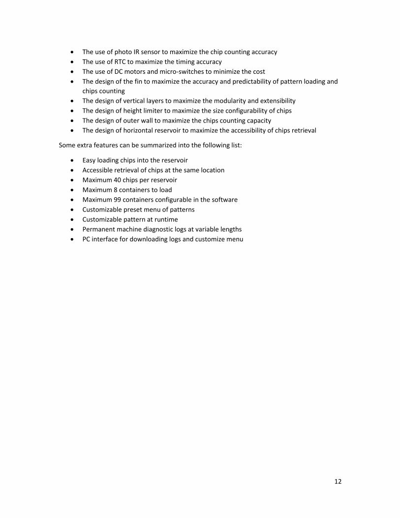
4.2 OPERATIONAL PROCEDURES
The bottom layer is designed for transport the containers to the chip loading site and to the lid
covering site. The design of a circular shape maximizes its capacity of 8 containers and allows
single DC motor to control the entire transportation flow.
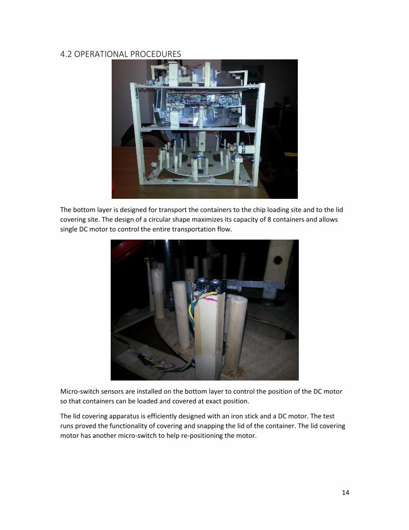
Micro-switch sensors are installed on the bottom layer to control the position of the DC motor
so that containers can be loaded and covered at exact position.
The lid covering apparatus is efficiently designed with an iron stick and a DC motor. The test
runs proved the functionality of covering and snapping the lid of the container. The lid covering
motor has another micro-switch to help re-positioning the motor.

15
The upper two layers are of same design for different colors of chips. The vertical design of the
machine allows adding more vertical layers to extend the capacity of the machine (i.e. more
chips and more colors) in the future. The design of the upper two layers contains the following
elements: reservoir wheel, central reservoir, arms, inner wall, height limiter, width limiter, fin,
straight lane, and outer wall.

16
The reservoir wheel is a big wood circular disk with radius of 20cm, driven by a 12V DV motor.
The wheel controls the entire motion of the chips in the upper two layers.
The central reservoir is the initial and final position of the chips. The design of the reservoir
allows user to dump all the chips into it without worrying about any jamming.
The arms are essential component which stretch from frame to the inner wall, providing
structural support for both inner and outer wall of the reservoir that does not move with the
reservoir wheel. One of the arms at each layer also supports the DC motor to stay at the center
of the disk.

17
The inner wall acts as a lane to guide the chips from the central reservoir to the chip exit
(loading) site. The inner wall gets narrower as closer to the exit to sort the chips into one lane.
However this is proven not sufficient. Width limiters are designed to stay on the inner wall to act
as a discontinuous point, which blocks the chips of multiple lanes into one lane.
Height limiter is designed to block chips of multiple layers into one layer. This stationary limiter
is proven to be effective with the reservoir wheel to rotate back and forth to unjam the chips. In
the proposal, it was proposed to be installed with dc motors, which was proven to be
unnecessary.
18
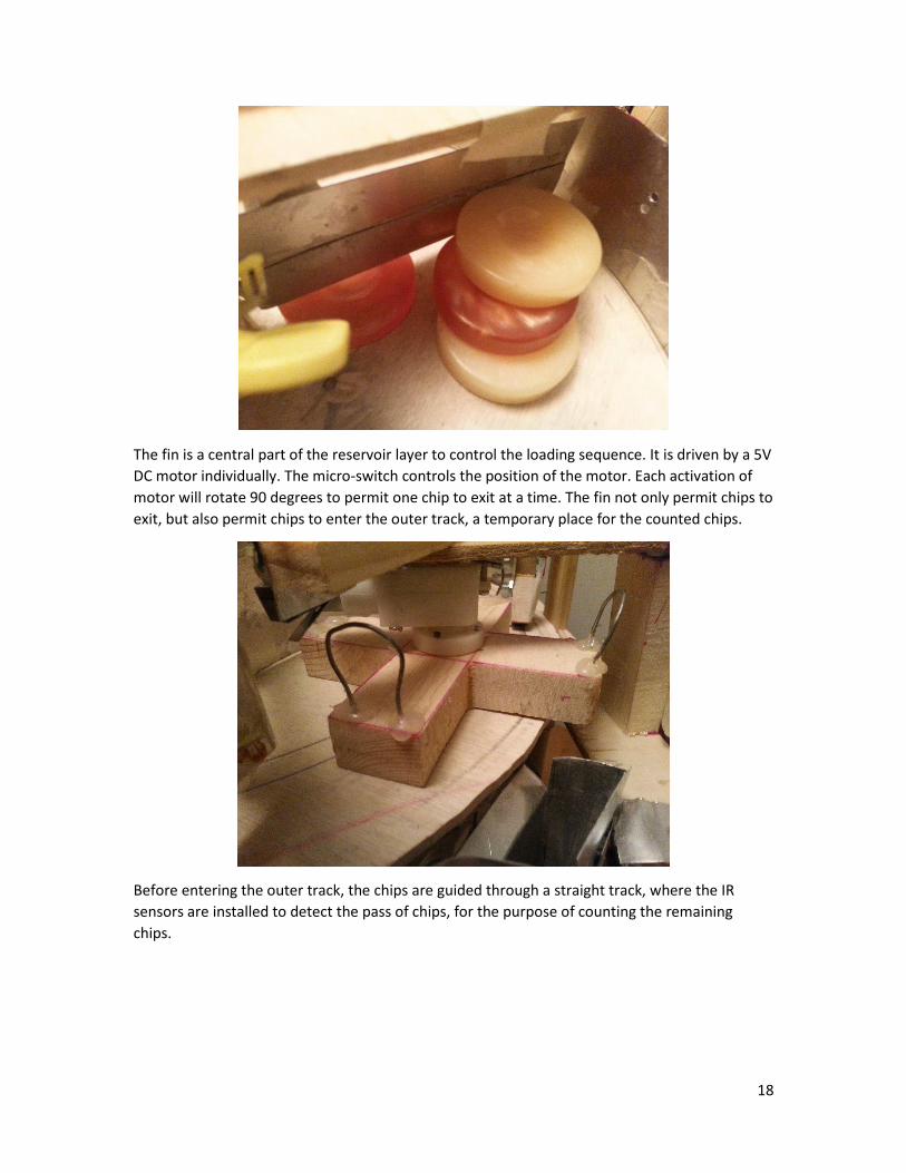
The fin is a central part of the reservoir layer to control the loading sequence. It is driven by a 5V
DC motor individually. The micro-switch controls the position of the motor. Each activation of
motor will rotate 90 degrees to permit one chip to exit at a time. The fin not only permit chips to
exit, but also permit chips to enter the outer track, a temporary place for the counted chips.
Before entering the outer track, the chips are guided through a straight track, where the IR
sensors are installed to detect the pass of chips, for the purpose of counting the remaining
chips.
19
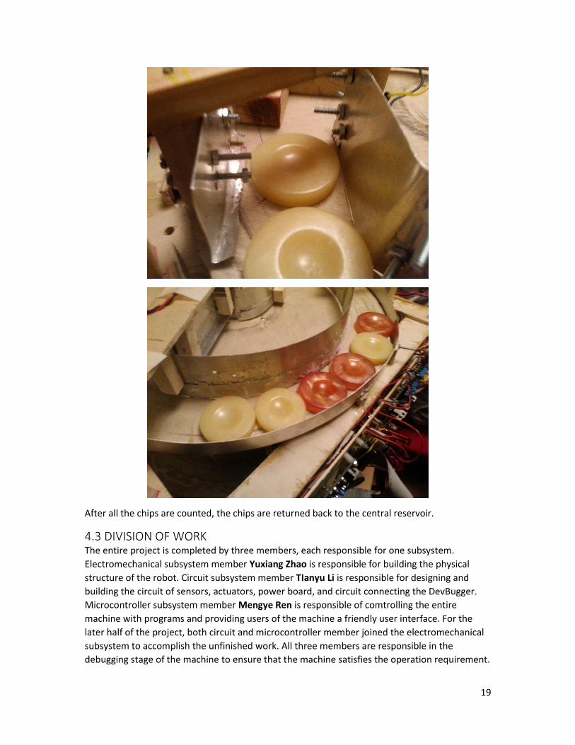
After all the chips are counted, the chips are returned back to the central reservoir.
4.3 DIVISION OF WORK The entire project is completed by three members, each responsible for one subsystem.
Electromechanical subsystem member Yuxiang Zhao is responsible for building the physical
structure of the robot. Circuit subsystem member TIanyu Li is responsible for designing and
building the circuit of sensors, actuators, power board, and circuit connecting the DevBugger.
Microcontroller subsystem member Mengye Ren is responsible of comtrolling the entire
machine with programs and providing users of the machine a friendly user interface. For the
later half of the project, both circuit and microcontroller member joined the electromechanical
subsystem to accomplish the unfinished work. All three members are responsible in the
debugging stage of the machine to ensure that the machine satisfies the operation requirement.

20
5 ELECTROMECHANICAL SUBSYSTEM
5.1 PROBLEM ASSESSMENT The above section already introduced the various mechanical components the machine has in
order to accomplish the tasks it was designed to do. The electromechanical system consists of
the entire mechanical structure of the machine, as well as various electrical components such as
motors and sensors and their assembly into the mechanical structures. Along with requirements
in the RFP that are already presented, the following are additional design requirements:
The chip is a circular object with a dimension of 45± 1 mm in diameter and 10±1 mm in
thickness. The weight of each chip is 20 ±1 g.
The container is cylindrical with a height of 107 ± 2 (excluding the cover) and inner
diameter of 52 ± 1 mm at the top and 48 ± 1 mm at the bottom. The cover is has a
diameter of 63 ±1 mm and a thickness of 12 ±1 mm.
The force needed to close the lid when acting on the lock of the lid is approximately
1000 g. This is derived from experiments
The coefficient friction between chips and chips derived from experiment is 0.67 (see
appendix * for derivation process)
After analyzing our solution and the RFP, the following design requirements for each of the
component are developed
FRAME The frame must be light but capable of withstanding the weight
Each level of machine must be removable with relative ease
WHEEL The wheel must be large enough to house the required wall structures. It also must
accommodate a reservoir that would hold at least 15 chips, 40 chips desired. The wheel
material should withstand the weight of the chips
The wheel motor must be strong enough to counter the friction force created by chips
and the bottom of the wall rubbing on the wheel
The bearing system for the wheel should have very low resistance but stable so that the
wheel is stable and does not wobble. The bearing system should withstand the weight
of the chips.
WALL The wall must be strong and rigid to withstand the impact and pressure from the chips.
It also should be constructed with an accurate suspension height from the wheel. The
holding mechanism should also be strong, rigid, light and easy to construct.
The wall structure should be carefully designed so that chips do not jam within the track,
especially around the fin area.
21
HEIGHT LIMITER The height limiter should attempt to reduce the height of chips from multiple chips
down to one chip. It should do so without causing jamming in the system
WIDTH LIMITER The width limiter should attempt to reduce the width of chips from two to three chips
down to one chip. It should do so without causing jamming
FIN The fin should dispense one chip and sent one chip to the counting reservoir in a simple
and controllable manner. This requires that only one chip should be inserted into each
of the fin compartments.
Chips and fin must work together without assistance of any sensors
Chips immediately outside of the fin should not interfere with the fin as the fin turns.
Any other potential jamming conditions should be discovered and resolved
Micro-switch should be integrated to indicate the fin has spun a quarter turn
LOADING TUNNEL Loading tunnel should catch all the chips as they are knocked out of the wheel by the fin.
There is a range of locations where this occurs, the loading tunnel should deal with all of
the situations
Chips loaded into the container should eventually lay down flat
STRAIGHT LANE AND COUNTING LANE The IR emitter and receiver pair as to be mounted low enough (<1 cm) so that the chip
can block of all the IR radiation
The emitter and receiver must be paired accurately so that the receiver can detect the
IR emissions
The emitter and receiver must be stable to withstand various movements and vibrations
The emitter and receiver must be replaceable
During reverse, the straight lane and the fin should work together so that the fin the
rotate back chips without guidance from the IR break point sensor
BASE 8 containers should be inserted onto the base. The containers should be locked firmly
onto the base. The insertion process should be convenient
The base motor and the bearing system should handle the weight of 8 X 10 chips, each
weighing 20 g.
One Micro-switch indicates the stop location for the loading zone and the other for the
lid closing zone. The sensors should be reliable and not interfere with containers
movement. Their position should also assist the base to stop at the precise location
required for loading and lid-closing.
LID CLOSING MECHANISM The DC motor used should provide at least 1000g of force at the lock of the container
22
The mechanism should not block the passage of containers
The mechanism should be reliable and simple to control
5.2 SOLUTIONS
5.2.1 FRAME
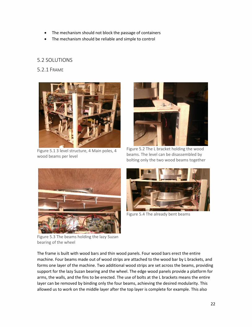
Figure 5.1 3 level structure, 4 Main poles, 4 wood beams per level
Figure 5.2 The L bracket holding the wood beams. The level can be disassembled by bolting only the two wood beams together
Figure 5.3 The beams holding the lazy Suzan bearing of the wheel
Figure 5.4 The already bent beams
The frame is built with wood bars and thin wood panels. Four wood bars erect the entire
machine. Four beams made out of wood strips are attached to the wood bar by L brackets, and
forms one layer of the machine. Two additional wood strips are set across the beams, providing
support for the lazy Suzan bearing and the wheel. The edge wood panels provide a platform for
arms, the walls, and the fins to be erected. The use of bolts at the L brackets means the entire
layer can be removed by binding only the four beams, achieving the desired modularity. This
allowed us to work on the middle layer after the top layer is complete for example. This also

23
meant additional layers could be added to the machine very easily, increasing the machine’s
functionality.
In our initial design, a large wood sheet is used to serve as the platform for each layer. Although
this method made each layer easier to construct and more modular, the machine was proven to
be too heavy (2.5 kg for the each layer, 8 kg predicated for the entire machine). It was thought
that only the edge and the middle beam of the wood sheet is used to carry the weight. Hence,
the frame and the layers were rebuilt to only include an edge and middle platform, which
resulted in the design above. The current design resulted in a weight of 5.8 kg
IMPROVEMENTS
Although the re-design solved the weight issue, the thin wood panel proved too fragile with
time. Figure 4.4 indicates the weight of the reservoir layer has caused the edge wood panel to
bend and hence, the structures on the panel began to sag. This caused nightmare issues with
the wall and the wheel as the wall would rest on the wheel with time, jamming the wheel.
Resilient materials, such as aluminum L channels, could be used instead of thin wood panels, as
they are resistant to bending forces while being light.
5.2.2 WHEEL
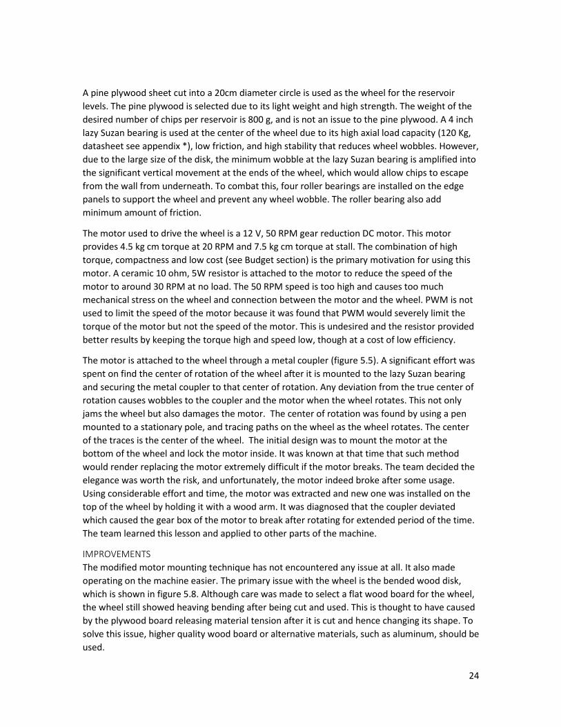
Figure 5.5 motor and the coupler
Figure 5.6 Roller bearing
Figure 5.7 The lazy Suzan bearing and the roller bearing
Figure 5.8 The bent wheel
24
A pine plywood sheet cut into a 20cm diameter circle is used as the wheel for the reservoir
levels. The pine plywood is selected due to its light weight and high strength. The weight of the
desired number of chips per reservoir is 800 g, and is not an issue to the pine plywood. A 4 inch
lazy Suzan bearing is used at the center of the wheel due to its high axial load capacity (120 Kg,
datasheet see appendix *), low friction, and high stability that reduces wheel wobbles. However,
due to the large size of the disk, the minimum wobble at the lazy Suzan bearing is amplified into
the significant vertical movement at the ends of the wheel, which would allow chips to escape
from the wall from underneath. To combat this, four roller bearings are installed on the edge
panels to support the wheel and prevent any wheel wobble. The roller bearing also add
minimum amount of friction.
The motor used to drive the wheel is a 12 V, 50 RPM gear reduction DC motor. This motor
provides 4.5 kg cm torque at 20 RPM and 7.5 kg cm torque at stall. The combination of high
torque, compactness and low cost (see Budget section) is the primary motivation for using this
motor. A ceramic 10 ohm, 5W resistor is attached to the motor to reduce the speed of the
motor to around 30 RPM at no load. The 50 RPM speed is too high and causes too much
mechanical stress on the wheel and connection between the motor and the wheel. PWM is not
used to limit the speed of the motor because it was found that PWM would severely limit the
torque of the motor but not the speed of the motor. This is undesired and the resistor provided
better results by keeping the torque high and speed low, though at a cost of low efficiency.
The motor is attached to the wheel through a metal coupler (figure 5.5). A significant effort was
spent on find the center of rotation of the wheel after it is mounted to the lazy Suzan bearing
and securing the metal coupler to that center of rotation. Any deviation from the true center of
rotation causes wobbles to the coupler and the motor when the wheel rotates. This not only
jams the wheel but also damages the motor. The center of rotation was found by using a pen
mounted to a stationary pole, and tracing paths on the wheel as the wheel rotates. The center
of the traces is the center of the wheel. The initial design was to mount the motor at the
bottom of the wheel and lock the motor inside. It was known at that time that such method
would render replacing the motor extremely difficult if the motor breaks. The team decided the
elegance was worth the risk, and unfortunately, the motor indeed broke after some usage.
Using considerable effort and time, the motor was extracted and new one was installed on the
top of the wheel by holding it with a wood arm. It was diagnosed that the coupler deviated
which caused the gear box of the motor to break after rotating for extended period of the time.
The team learned this lesson and applied to other parts of the machine.
IMPROVEMENTS
The modified motor mounting technique has not encountered any issue at all. It also made
operating on the machine easier. The primary issue with the wheel is the bended wood disk,
which is shown in figure 5.8. Although care was made to select a flat wood board for the wheel,
the wheel still showed heaving bending after being cut and used. This is thought to have caused
by the plywood board releasing material tension after it is cut and hence changing its shape. To
solve this issue, higher quality wood board or alternative materials, such as aluminum, should be
used.
25
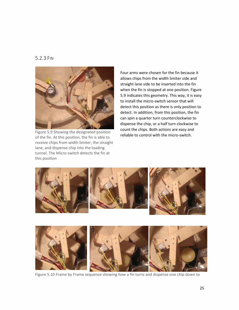
5.2.3 FIN
Four arms were chosen for the fin because it
allows chips from the width limiter side and
straight lane side to be inserted into the fin
when the fin is stopped at one position. Figure
5.9 indicates this geometry. This way, it is easy
to install the micro-switch sensor that will
detect this position as there is only position to
detect. In addition, from this position, the fin
can spin a quarter turn counterclockwise to
dispense the chip, or a half turn clockwise to
count the chips. Both actions are easy and
reliable to control with the micro-switch.
Figure 5.10 Frame by Frame sequence showing how a fin turns and dispense one chip down to
Figure 5.9 Showing the designated position of the fin. At this position, the fin is able to receive chips from width limiter, the straight lane, and dispense chip into the loading tunnel. The Micro-switch detects the fin at this position
26
the loading tunnel
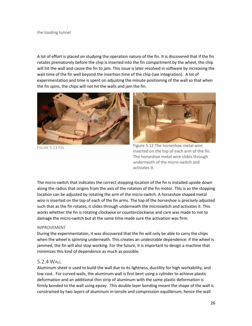
A lot of effort is placed on studying the operation nature of the fin. It is discovered that if the fin
rotates prematurely before the chip is inserted into the fin compartment by the wheel, the chip
will hit the wall and cause the fin to jam. This issue is later resolved in software by increasing the
wait time of the fin well beyond the insertion time of the chip (see integration). A lot of
experimentation and time is spent on adjusting the minute positioning of the wall so that when
the fin spins, the chips will not hit the walls and jam the fin.
FIGURE 5.11 FIN
Figure 5.12 The horseshoe metal wire inserted on the top of each arm of the fin. The horseshoe metal wire slides through underneath of the micro-switch and activates it.
The micro-switch that indicates the correct stopping location of the fin is installed upside down
along the radius that origins from the axis of the rotation of the fin motor. This is so the stopping
location can be adjusted by rotating the arm of the micro-switch. A horseshoe shaped metal
wire is inserted on the top of each of the fin arms. The top of the horseshoe is precisely adjusted
such that as the fin rotates, it slides through underneath the microswitch and activates it. This
works whether the fin is rotating clockwise or counterclockwise and care was made to not to
damage the micro-switch but at the same time made sure the activation was firm.
IMPROVEMENT
During the experimentation, it was discovered that the fin will only be able to carry the chips
when the wheel is spinning underneath. This creates an undesirable dependence: if the wheel is
jammed, the fin will also stop working. For the future, it is important to design a machine that
minimizes this kind of dependence as much as possible.
5.2.4 WALL Aluminum sheet is used to build the wall due to its lightness, ductility for high workability, and
low cost. For curved walls, the aluminum wall is first bent using a cylinder to achieve plastic
deformation and an additional thin strip of aluminum with the same plastic deformation is
firmly bonded to the wall using epoxy. This double layer bonding meant the shape of the wall is
constrained by two layers of aluminum in tensile and compression equilibrium; hence the wall

27
becomes very rigid and difficult to bend. For straight walls, a perpendicular edge is created by
bending the bottom edge of the aluminum sheet and made the aluminum rigid. These solved
the aluminum softness issue.
Figure 5.13 double bonded layer provides rigidty to the wall
Figure 5.14 The bent edge strenghts the aluminum wall so that it is no longer bendable
Figure 5.15 One of the arms that erects the wall. The cylindrical rode is bolted to the wall and
allows for minor adjustment to wall position by simple rotation
Arms and poles made out of wood cylinders are used to erect the wall above the wheel. The arm
is made out of wood cylinders so that they can be rotated in order to adjust the position of the
wall. The pools are bolted onto the four beams. The height of the poles is precisely adjusted so
that the height of the wall from the wheel is on average 4 mm. However, due to the bent wheel,
this proves to be extremely challenging. Since the top priority is to not allow chips to escape the
wall, a soft sponge sheet is added at the bottom of the wall and is made to scrape the wheel.
The sponge sheet stops the chips from escaping, and has low noise and friction when scraping
on the wheel. Additional helper arms are made to further secure the wall. They are made with
balsa wood so the weight added is virtually non-existent. Appendix * shows the dimensions and
layout of the walls on the reservoir layer. The dimensions are made so that the chips can pass
smoothly.
28
5.2.5 HEIGHT LIMITER
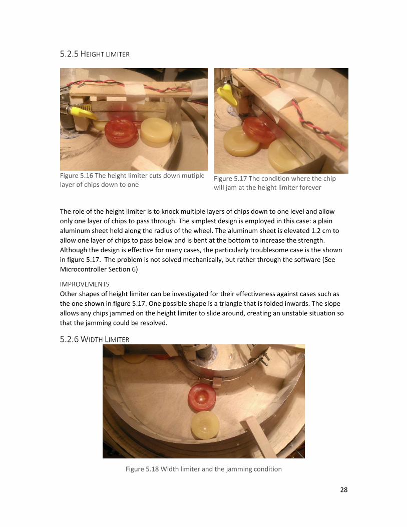
Figure 5.16 The height limiter cuts down mutiple layer of chips down to one
Figure 5.17 The condition where the chip will jam at the height limiter forever
The role of the height limiter is to knock multiple layers of chips down to one level and allow
only one layer of chips to pass through. The simplest design is employed in this case: a plain
aluminum sheet held along the radius of the wheel. The aluminum sheet is elevated 1.2 cm to
allow one layer of chips to pass below and is bent at the bottom to increase the strength.
Although the design is effective for many cases, the particularly troublesome case is the shown
in figure 5.17. The problem is not solved mechanically, but rather through the software (See
Microcontroller Section 6)
IMPROVEMENTS
Other shapes of height limiter can be investigated for their effectiveness against cases such as
the one shown in figure 5.17. One possible shape is a triangle that is folded inwards. The slope
allows any chips jammed on the height limiter to slide around, creating an unstable situation so
that the jamming could be resolved.
5.2.6 WIDTH LIMITER
Figure 5.18 Width limiter and the jamming condition

29
The width limiter has circular wall that has a larger curvature than the inner reservoir wall; the
continuously reducing width limits multiple chips down to one chip. From experiments, two
chips often times can jam together as the width narrows. This is somewhat resolved by adding a
wood piece on to the inner wall to provide a bias towards the chips on the outer track. This is a
natural fit because the chips on the outer track already moves faster than the chips on the inner,
hence biasing towards them is more effective. However, the identical jamming situation still
occurs (figure 5.18). We hypothesized that no matter the configuration, there is always a point
where such jamming will occur. We minimized this jamming with software (see Microcontroller
section)
IMPROVEMENTS
Instead of modifying the width limiter, one possible solution is to create bumps on the wheel
surface. This way, as the wheel turns beneath the jammed chips, the bumping provided by the
wheel will be enough to knock the chip loose and resolve the jam.
5.2.7 STRAIGHT LANE AND OUTER LANE
Figure 5.19 Chips returning the resevior are fed contiuneously into the fin. The fin is able to handle this situation
Figure 5.20 the break point IR sensor. The emitter on the left, the reciever on the right
The purpose of the straight lane and the outer lane is to collect, store and return the counted
chips. The straight lane is built to feed the chips into the compartment of the fin just like it is
shown on figure 5.19. It is only at this position that the fin can rotate blindly and still be able to
carry the chips back to the reservoir without any chance of jamming. The straight lane also
provided a platform to install the breakpoint IR sensors which are used for counting. The IR
emitter on one side continuously emits IR radiation, which is detected by the receiver on the
other side. When a chip passes through, it blocks off all the IR radiation and the receiver no
longer receives them, this trigger a change in state in the sensor that is detected by the
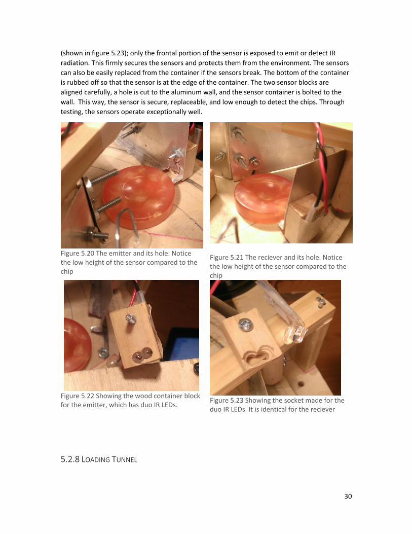
Microcontroller. A wood block is used as a container for the two sensors (shown in figure 5.22).
A socket is carved for the sensor such that the sensor can be inserted firmly into the hole
30
(shown in figure 5.23); only the frontal portion of the sensor is exposed to emit or detect IR
radiation. This firmly secures the sensors and protects them from the environment. The sensors
can also be easily replaced from the container if the sensors break. The bottom of the container
is rubbed off so that the sensor is at the edge of the container. The two sensor blocks are
aligned carefully, a hole is cut to the aluminum wall, and the sensor container is bolted to the
wall. This way, the sensor is secure, replaceable, and low enough to detect the chips. Through
testing, the sensors operate exceptionally well.
Figure 5.20 The emitter and its hole. Notice the low height of the sensor compared to the chip
Figure 5.21 The reciever and its hole. Notice the low height of the sensor compared to the chip
Figure 5.22 Showing the wood container block for the emitter, which has duo IR LEDs.
Figure 5.23 Showing the socket made for the duo IR LEDs. It is identical for the reciever
5.2.8 LOADING TUNNEL

31
The loading tunnel took a simple design. It is
a rectangular tunnel that connects from the
top layer to the mouth of an open container.
The portion of the tunnel from the second
layer to the mouth of the container is angled
in so that the tunnel can actually connects
with the mouth of the container. After
experimentation, it was found that chips can
sometimes drop into the container vertically.
A curved bend was given to the angled
portion of the tunnel. This is so that when
chips go through it, it is rotated towards the
horizontal inside of the tunnel, and reduces
the chances of landing vertically in the
container. The exact angle is found by
experimentation. This solved the issue.
Several piece of the aluminum panel are
added to the top and middle layers. This is
because chips are often thrown out to
different locations by the fin and the
aluminum panels direct the chips down to
the tunnel.
5.2.9 BASE
Figure 5.25 The base wheel and the cylindrical poles that secures the cylinders in place
Figure 5.26 The motor mounting mechanism
To secure 8 containers on to the base, three wood cylinders per container are nailed on to the
base. The wood cylinder provides a slot to insert the containers and will firmly secure the
cylinders in place. The other option is to make holes where the cylinder can be inserted into.
Figure 5.24 The loading tunnel. Notice the last portion is curved

32
This option require a thicker wood wheel and wood wheel being elevated, both of which are
undesirable in our design. The bearing system used for the base is identical to the wheel on the
reservoir level: a lazy Suzan bearing is used at the center, and four small roller bearings are
installed at the edge of the wheel. The motor used is a 5V worm gear motor, though it is capable
of handling 12V power if it is needed. This decision was made because of the need to cut on cost
and weight; the base is assumed to have low friction even with heavy containers loaded on it
due to the use of the bearing system, hence high power motor is not required. The motor is
mounted on a wood support beam, which is bolted to the bottom of the middle layer. Holes
were carved out of the unused portion of the base wheel to reduce weight.
Figure 5.27 Showing thee mounting method and the postion of three senors. From the closest to the furthest: load zone sensor, Lid closing zone sensor, lid closing mechanism initial position sensor
Figure 5.28 The sensor is mounted such that it is tanget just over the edge of the base wheel
Figure 5.29 The container rotates by, the body of the container presses on the micro-switch
Figure 5.30 As soon as the container clears the switch, it is directly below the load tunnel. This feature is used in the software to precise postion the container.
The micro-switch for detecting if a container has entered the loading zone is mounted on top of
a wood pole. The sensor is immediately beside the base wheel; as a container spins through it,

33
the body of the container will press on the lever of the micro-switch, hence activating it. The
sensor is mounted before the loading zone; the thinking was that the motor should be notified
beforehand so that the momentum can be absorbed. Coincidentally, the tip of the long lever of
the micro-switch is position directly below the loading zone. This feature is later used in
software to accurately position the container into the loading zone. For the lid closing zone, the
micro-switch is mounted in a similar manner.
BASE MOTOR FAILURE
Although it was initially assumed that the base would have low friction due to the bearing
system, the low quality of craftsmanship put into the base result in large bumps underneath the
base wheel. This interfered with the rollers and required extra power from the motor to drive it.
The motor was given 12 V but the performance showed signs of deteriorations as time went by.
Although the team notices such problem, we did not attribute it to damages done to the motor
by 12 V since the motor’s operating voltage is rated 5V – 15V. In addition, the method of
mounting the motor on to a support beam bolted to the second layer proven to be difficult to
remove the motor; top two layers have to be removed in order to access the motor. Such large
operation to our already delayed schedule is unaffordable; we needed time to debug and test.
Hence, the decision was made to continue use this motor. The motor performed satisfactorily
for the duration of our tests; however, the bumps on the underneath of the wheel continue to
jam the base wheel, rendering it impossible to stop at the precise loading zone. On
demonstration day, the decision was made to put sponge sheets on the rollers to absorb the
bumps. This worked but also added friction to the base wheel and the motor can no longer turn.
The motor was then pulsed to squeeze out for torque to drive the base. It turned but moments
later the motor was burnt. At the time of the incident it was 10 minutes before the
demonstration.
ANALYSIS OF THE CAUSE AND IMPROVEMENTS
There are three primary causes of the incident. First, the construction quality of the base wheel
is too low. Nails used to secure the cylindrical wood poles for each container protrudes from the
bottom. There are also major places where the wood has chipped. All these deficits are located
on the outer rim of the wheel where the roller must be installed; there are no other places for
the rollers. The rollers also needed because the containers loaded with chips are so heavy that
they bend the base wheel to the point where the base motor cannot spin. By installing the
rollers the situation is helped but the motor is still too weak to spin, due to the poor
construction quality. For improvements, built quality should be drastically strengthened,
especially in critical components such as the base wheel; every operation made should be made
in full consideration of the consequences to the end product. The second primary cause is the
use of a worm gear 5V DC motor and giving it 12V in order to turn. Although the operating
voltage is rated from 5V to 15V, by giving it 12 V and later pulsing it is obviously pushing the
motor to the limits. Under such condition, it is not unexpected that the motor will break. In
addition, worm gear plastic motors are not at all built to handle such tough task. Its damage is
also expected. For improvements, a more powerful and resilient full metal gear motor should be
used, such as the one used for the reservoir layers. A few grams savings in weight does not
warrant a compromise in such critical component of the machine. The third reason is continue
to use the motor fully aware of the decreased performance. Although it was not attributed to

34
the motor damages, a thoughtful and through investigation should be conducted to determine
the exact root cause of the issue before proceeding with anything else.
5.2.10 LID CLOSING
Figure 5.31 The lid closing mechansim.
Our solution uses a single DC motor to close and snap the lid of the container. Figure 5.31 shows
the helix shape of the lid closing arm. The lid closing arm works in the principle that for any arm
fixed shape arm to close the lid, its axis of rotation must match the axis rotation of the lid.
However, this poses a problem as the same axis of rotation requirement would make the arm
block the motion of the container. The circular base wheel already provides a solution, the
container will move away from the axis of rotation as it is rotated. The arm only need to provide
a clearance region to clear the passing the container and it is still able to be on the same axis of
rotation as the container. Our initial proposal solicited an arm that is held in on both sides by
poles. Actual experimentation found that such design would require a long arm and would
exceed the size constraint. A solution that require one end to be held is raised, and through
repeated testing and experimenting, the helix shape as it is used now is found to be the most
effective. The arm could simply be mounted directly to the motor shaft, and the container has
to enter a zone with a range of 4 cm for it to work, which is generous. The DC motor selected is
the same 50 RPM 12V motor as used on the reservoir levels.

35
Figure 5.10 Frame by Frame sequence showing how a lid closing mechanism turns, catches the lid, closees the lid, and snapes the lid
IMPROVEMENTS
Although the lid closing mechanism is able to snap on the lid very well, it is still quiet unstable.
This is largely due to the base wheel’s inability to position the container xactly at the center of
the zone. It is also relies on the angle of the container; the container lid must face outwards in
order for it work most reliably. Since there is no sensor indicating the closed position of the arm,
a time delay is set to stop of the motor from turning continuously. However, this is not always
reliable and in event where the arm does not catch a lid, the motor will over rotate and damage
other component in the machine.
6 CIRCUIT SUBSYSTEM
6.1 PROBLEM ASSESSMENT AND DESIGN REQUIREMENTS The circuit subsystem has four responsibilities: 1. Provide stable and safe power to all actuators,
sensors, their associated electronic components and the microcontroller. (Power Supply) 2.
Providing the system by which Microcontroller signals can be safely and accurately interpreted
into actuator movements. (Actuators) 3. Providing the system by which sensors responses are
interpreted into a signal that is easily and safely consumable by the Microcontroller (sensors). 4.

36
Providing the environment by which circuit systems can fully operate in a safe, protected, and
reliable manner. (Circuit panel and cable management)
1. Power supply and distribution
a. Provide 12V at 2A maximum 5V at 2A maximum for the continuous operation of
all actuators, circuits and microcontroller. Detailed power budge is shown in
section *. The main power supply can be a power adapter that plugs into regular
wall socket since the machine is stationary. However, the weight of the power
supply should be light since it is counted in the total weight of the machine; the
power supply should not exceed 500g.
b. Microcontroller and sensors require a stable, regulated and noise-free 5V power
source to work safely and reliably. Over voltage/current protection and wrong
polarity protection should also be present for these delicate electronic devices.
This infrastructure is provided by the power system.
c. DC motors generate noise, high current spikes, high voltage spikes, and wrong
polarity when operating. These electrical anomalies would cause more delicate
electronic devices, such as sensors and Microcontrollers to operate unreliability
or even damage them. Since some DC motors (see section *), Microcontroller
and sensors all operate on 5V source, the power system needs to isolate the
delicate electronic devices from the DC motors. This will also help to achieve
requirement b.
d. An emergency stop is implemented. The emergency stop is a physical switch or
a push button that can be triggered easily. It should also be mounted in an easily
accessible place. Upon triggering the emergency stop, the machine must
completely stop moving and hence remove any threats that caused the stop to
be triggered in the first place. The machine should resume its operation when
the emergency stop is lifted. These requirements are in accordance with the RFP.
2. Sensors
a. IR emitters and receivers running in a breakpoint sensor configuration are
needed to detect the passage of chips
b. Microswitch is used to detect the location that the fin has spun to
c. Microswitch is used to detect if a chip container has entered the loading zone
and the lid closing zone
d. Microswitch is used to detect if the lid closing arm has spun to the correct initial
condition
e. Sensor circuit needs to output TTL digital signal with the appropriate voltage
level for digital high and digital low into the Microcontroller to be consumed
f. Sensors and sensors circuits should be detachable and easily connectable. This is
to increase the flexibility of the sensor attachment during integration.
3. Actuators
a. Be able to drive 6 DC motors with start/stop and bi-direction capabilities.
Microcontroller gives a two bit signal to specify the three states: clockwise,
counterclockwise, and stop.

37
b. Each driver circuit needs to deliver 2A max current. Figure * shows current
requirements of all motor used.
c. Driver circuit should protect the rest of the circuit system from current spikes,
voltage spikes and reverse polarity generated by DC motors
d. Buffers are needed for all driver input signals to protect the Microcontroller
from abnormalities generated in the driver circuit.
4. Circuit panel, cable management, and other design requirement
a. All circuits should be mounted on a circuit panel and should be easily
disassembled and replace when necessary
b. Connections between circuits should be easily assembled and disassembled to
increase modularity and reparability. Connection mechanism should also be
reliable and safe to reduce the chance of loose connections and short circuits
c. Circuits should be modularity to increase resistance to breaking and flexibility
when integrating into the machine
d. Circuits and electrical components such as sensors and motors should also be
pluggable to increase modularity, flexibility, and reparability
e. Wires should be shortened to increase elegance and minimize noise
f. Circuit system should have LED indicators to indicate the states of all sensor
output signals and motor input signals in order to help with the debugging
process.
6.2 SOLUTIONS
6.1 OVERVIEW In accordance with the above design requirements, the following comprehensive circuit
system is designed.
Power system
o main power board
o Power supply connection board
Sensor system
o main sensor board
o secondary sensor board
Actuator driver system
o 6 full H-bridge DC driver boards
o Buffer board
Microcontroller System
o Signal routing board
6.2 POWER BOARD

38
Figure 5.1 Power Bord
The role of the power board is to take the two power supply output, 12v and 5v, and distributed
to the entire machine according to the voltage requirements of each component. DC motors
generate high voltage and current spikes and high noise when operating, and these
abnormalities will propagate to any circuitry connected to the same power source as it. As we
have two motors running on 5V power source, in order to satisfy the regulated and noise-free
power requirement of sensors and Microcontroller, an additional 5V power source must be
constructed and must be block off voltage/current spikes and noise generated from the motors.
The power board does this by taking the 12V power source from the power supply, and
regulates it to a 5 V power source by using a LM7805 voltage regulator. The LM7805 voltage
regulator is able to regulate an input voltage from 7.5 v to V, hence it provides over voltage
protection. The LM7805 has built-in over current protection and is able to output maximum 1A;
this forms the over current protection. A power diode is attached between the regulated power
ground and the un-regulated power ground. It allows current to only flow from the regulated
ground to the un-regulator ground; this forms the reverse polarity protection for the regulated
power source. A 67 uF capacitor grounds the 12 V input to the voltage regulator to dampen any
noise generated from the DC motors before they enter the voltage regulator. An additional 3
1uF ceramic capacitor grounds the regulated 5V power source to further dampen any noise
from the voltage regulator. From observations using an oscilloscope, this step up is enough to
remove any noise generated from DC motors. The full schematic is shown on Appendix 13.2.1.2
and is labeled as section A. Power line 1 is the regulated 5V and ground for sensor boards,
buffer board, and Microcontroller. These boards are placed here because their sensitive nature,
the existence of logic chips, and the requirement of a common ground if order for digital signals
for the Microcontroller to work. Power line 2 is the unregulated 5 V for the fin motors and their
associated driver circuit. Power line 3 is the unregulated 12 V for the base motor, sorter wheel
motor, the lid motor, and their associated driver circuit. Motor power sources are all

39
unregulated because motors and their driver circuit are not sensitive to noise and
voltage/current spikes in the power source.
The power board also integrates the emergency stop switch. The emergency stop chosen is a
toggle SPDT switch. This decision is made instead of a pushbutton because the state of the
emergency stop has to be remembered in hardware, which although is doable with a
pushbutton, the fear at the design stage was that it may not be reliable. A SR latch is
implemented to translate SPSD switch state into a digital high or low. This is done because the
state of the switch must be reported to the Microcontroller, and it must be used to control the
current flow of both 5V and 12V power line. Having to create a single digital signal and consume
such signal in multiple places is the more elegant and reliable. The decision is made to shut off
only power to the motors when the emergency switch is activated and leave all sensors and
microcontroller remaining active. There are several advantages to this system. First, all motors
are stopped regardless of what signal it received, which is guaranteed to be predictable and
reliable. Second, the Microcontroller can retain its operation state and resume its operation in
the event the emergency switch is activated. Third, the Microcontroller can also display
additional messages to users when the emergency switch is activated. Fourth, since the sensor
boards and buffer boards are also not affected, their LED indicators can indicate the state of all
sensor input signals and motor output signals without having actual motors connected; this is
tremendous help to the debugging process since one can verify the correctness of all signals
without risking unexpected motor movements; this also protected many accidents where the
wrong signal was sent to motor driver circuits where it could have burned the driver circuit. In
addition, this system also fits naturally with the existing power board configuration: the power
to sensor boards, buffer board, and Microcontroller is already separated by the voltage
regulator from the motor power; a switch mechanism for the two motor power lines that is
controllable by the emergency switch signal would suffice. A mechanical relay is chosen for this
purpose. The AXCOM P2 Signal relay has two separate SPSD switches controlled by one source
signal and each is used to control one of the two motor power lines. Since the current from the
digital signal is not large enough to switch on the relay (25mA supplied, 40 mA needed), a
general purpose 200mA signal transistor is used to amplify the signal from the switch and switch
on the relay. The switch signal is also connected to the Microcontroller. Section B on Appendix
13.2.1.2 shows the circuit schematics. Three LEDs indicate the operation state of power board;
the red LED indicate the signal output of the emergency switch, two green LEDs indicate the
current flow in the motor power lines. This allowed us to easily debug any problems with the
power and emergency switch.
6.3 POWER SUPPLY AND POWER SUPPLY CONNECTION BOARD The power supply used is a SuperPower AC adapter rated at 100V-240V VAC 60HZ for input, and
12V at 2A and 5V at 2A for output. Although from the power budget table we can see that the
maximum current for each of the sort wheel motors is 2 A, that is the stall current of the motor
and we do not expect the motor to completely stall. As indicated, the power supply is definitely
enough to sustain the average operation current of the entire system. Main advantage of the
power supply is its weight, which is 200g. As the power supply lacks a master switch, a master
switch is created along with a power supply connection board to house it. The power supply
connection board is connected to the power board by 12V, 5V and ground wires.
40
6.4 SENSORS
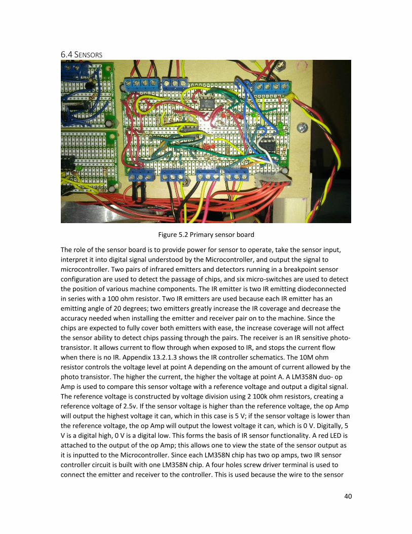
Figure 5.2 Primary sensor board
The role of the sensor board is to provide power for sensor to operate, take the sensor input,
interpret it into digital signal understood by the Microcontroller, and output the signal to
microcontroller. Two pairs of infrared emitters and detectors running in a breakpoint sensor
configuration are used to detect the passage of chips, and six micro-switches are used to detect
the position of various machine components. The IR emitter is two IR emitting diodeconnected
in series with a 100 ohm resistor. Two IR emitters are used because each IR emitter has an
emitting angle of 20 degrees; two emitters greatly increase the IR coverage and decrease the
accuracy needed when installing the emitter and receiver pair on to the machine. Since the
chips are expected to fully cover both emitters with ease, the increase coverage will not affect
the sensor ability to detect chips passing through the pairs. The receiver is an IR sensitive photo-
transistor. It allows current to flow through when exposed to IR, and stops the current flow
when there is no IR. Appendix 13.2.1.3 shows the IR controller schematics. The 10M ohm
resistor controls the voltage level at point A depending on the amount of current allowed by the
photo transistor. The higher the current, the higher the voltage at point A. A LM358N duo- op
Amp is used to compare this sensor voltage with a reference voltage and output a digital signal.
The reference voltage is constructed by voltage division using 2 100k ohm resistors, creating a
reference voltage of 2.5v. If the sensor voltage is higher than the reference voltage, the op Amp
will output the highest voltage it can, which in this case is 5 V; if the sensor voltage is lower than
the reference voltage, the op Amp will output the lowest voltage it can, which is 0 V. Digitally, 5
V is a digital high, 0 V is a digital low. This forms the basis of IR sensor functionality. A red LED is
attached to the output of the op Amp; this allows one to view the state of the sensor output as
it is inputted to the Microcontroller. Since each LM358N chip has two op amps, two IR sensor
controller circuit is built with one LM358N chip. A four holes screw driver terminal is used to
connect the emitter and receiver to the controller. This is used because the wire to the sensor

41
would be long and loose strand wire is used instead of pin wires to reduce cost, and this allows
one to securely connect loose strand wires.
Micro-switches also use similar controller mechanism to output a digital signal instead of being
connected directly to the Microcontroller. This is because doing so would is unsafe and poses
too much danger to the delicate Microcontroller. Appendix 13.2.4 shows the schematics for the
micro-switch controller and the micro-switch used. The micro-switch is a SPDT switch. A
LM385N op Amp is used to compare the voltage from the micro-switch to a reference voltage.
One terminal of the micro-switch is connected to 5 V source and the other terminal is grounded.
The reference voltage is created by two 10 k ohm resistors. One switch is touching one terminal,
the sensor voltage is 5V and is higher than the reference voltage, the op amp outputs 5V; when
the switch is flipped and touching the other terminal, the sensor voltage is 0V and is lower than
the reference voltage, the op amp outputs 0V. Outputs are compatible with the Microcontroller
and LED is also attached at the output to visualize the sensor output for debug purposes. Screw
driver terminals are also used. Four of these identical controllers are located on the main sensor
board, addition one is located on the secondary board due to space issues.
6.5 ACTUATOR DRIVERS
Figure 5.3 A cluster of 3 H-bridges
The actuators used in this machine are 6 DC motors requiring start/stop and bidirectional
functionality. Hence, the ideal driver circuit for each of the DC motor is a full H-bridge. Appendix
13.2.1.1 shows the schematic of the H-bridge circuit. The maximum stall current of the 12V DC
motor is 2A; it is the largest current draw device in the machine. TIP122/TIP127 can provide a
maxmium current draw of 5A, hence they are selected as the transistor for the full H-bridge
circuit. Although TIP112/TIP117 is cheaper and has less maximum current hence is suitable for
the two small fin motors, the reduction in price is very small and is not worth the decrease in
exchangeability between H-bridge circuits of different types. Therefore, all H-bridge circuits are

42
constructed identically with TIP122/TIP127 so that they are interchangeable and increase the
ease of installation and the ease of replacement. Extra general purpose 200mA transistors are
added to the traditional H-bridge circuits as it is shown on the schematics. This transistor serves
as a protection gate between the small and stable current in the digital signal and the large and
unstable current in the driver circuit. DC motors often generate reverse current going through
the base of the power transistor. This transistor can also stop the reverse current reaching the
digital circuits that generate the motor signals. The resistors are also calculated precisely to limit
the current and protect the transistors. Each H-bridge circuit is constructed on a single board
and controls only one motor. Although this design adds extra redundancy during wiring, board
usage and layouts, it is worth the price to pay for ease of replacement, since H-bridge circuits
are easily destroyed when the signals inputted are incorrect. Two signals controls the transistors
on either side to open; if the both sides are opened, the H-bridge will short circuit, and cause
the transistor to burnout. We combat this by using the emergency switch to shut off the motor
power, and observe the correctness of the motor signal through the LEDs on the buffer board
(discussed below) before turning the motor power back on. This and along with careful H-bridge
design, allows us to reduce H-bridge and buffer burnouts to zero during the debugging stage and
final runs.
Initially a decoder circuit made out of AND gates and NOT gates are used to control the H-bridge.
The Micro-controller provides the enble and direction signal, and the logic gates turns these two
signal into S0, S1 signal for each side of the H-bridge. This circuit is later found extremely
unreliable during the testing stage, partly because it does not have drop down resistors.
Whenever the micro-controller is floating, the logic output floats as well, and send wrong signal
to the H-bridge. Later, this was changed to a simpler buffer system and drop down resistors was
added.
Figure 5.4 Buffer board. Notice the indicator LEDs

43
The buffer board contains two CD6070 buffer chips to isolate the driver circuits from the
Microcontroller. This is to protect the Microcontroller from the expectances in the driver circuit.
The buffer board also has a drop down resistor on each of the input signal from the
Microcontroller. The resistors pull the input signals down to ground when the input signal is
floating but still retains the input signal’s state in normal operation. To do this, resistors with
resistance that matches the internal resistance of the buffer is used. The issue of floating was
very apparent when programming Microcontroller and H-bridges are involved. When
programming the Microcontroller, all inputs were floating which causes both sides of the H-
bridge to open and burns the H-bridge. Drop down resistors were added later on to the buffer
board and completely resolved this issue. LED indicators also installed on the output signals of
the buffers. From them one can view the state of each motor signal, which helped tremendously
in the debugging process. Appendix 13.2.1.5 shows the schematics of one of the buffer system.
6.6 MICROCONTROLLER AND SIGNAL ROUTING BOARD
Figure 5.5 Signal routing board
The Devbugger board is used for the microcontroller. The decision was made because of the
presence of RTC, USB, and programmer components that are needed for the machine’s software.
The complexity and the potential reliability issues in building these ourselves far outweighs the
reduction in weight and cost that the DevBugger was selected. Because the DevBugger is often
detached from the machine for programming purposes, a signal routing board is built to
permanently collect all the signal connections and route them to the correct pin assignment on
a 40pin IDC cable. The DevBugger board is connected to all the signals through the 40 pin IDC
cable. In addition to signals, the DevBugger’s regulated 5 V Vcc and three ground pins are also
routed into the 40 pin IDC cable and connected to the power board’s 5 V regulated power
source and the associated ground line. This allows the DevBugger to run on power supply power
and no additional cables. Throughout the testing and running, the DevBugger has not

44
experienced issues with inferences from other parts of the circuit. This is a testament to the
protection and de-noise capabilities build into the power board.
6.7 CIRCUIT PANEL AND CABLE MANAGEMENT Including the DevBugger, there are 12 circuit boards in total. To make the installation has easy
as possible and reduce the amount of wiring present, all circuit boards are installed on to a
wood board and forms a circuit panel. Circuits are installed on both sides of the circuit panel to
reduce the amount of wood used, and wires are made to go through the circuit panel to connect
boards on either side. The circuit panel is attached to the machine by two screws. The
requirement that all circuit must be dissembled and assembled easily meant soldering them
together is not an option; connectors must be used. As result, the focus is then shifted to find a
secure connector that does not come off easily. Screw driver terminals are used because it was
assumed that they would provide the benefit of easily installation (wire can detached and
plugged) while being secure enough so that no loose connection can occur. However, for power
boards, buffer boards, and signal distribution board, the number of ports are too high to use
screw driver terminals. After considered that fact all these connections are made in between
circuits and the distance between them are short, a pin to pin wire is selected. Wiring posed a
significant issue to the integration process. The details of which is explained in the integration
section. Improvements in this area should definitly be made.

45
7 MICROCONTROLLER SUBSYSTEM (SOFTWARE)
7.1 OVERVIEW The role for the software component of the Chip Washer machine is to provide users a better
human-device interaction interface and control the mechanical components with more accurate
algorithm during runtime.
7.2 PROBLEM ASSESSMENT The software of the machine needs to have following functionality to accommodate the normal
operation of the machine as required by the RFP:
Usable user interface that accomplish all the relevant configuration of a qualified
machine operation
Allow user to enter the patterns for containers
Display emergency stop information
Display pattern loaded
Accurately control motors bi-directionally to stop at desired location based on sensor
readings during chips loading and lid covering
Actively read sensor information to count number of chips left
Display time information of the operation
Display number of chips left
The solution and implementation of the functionalities above are explained into detail in the
solution subsection.
In terms of programming stype, the software programming should use separate code files for
different functional purposes, which provides great maintainability of the software. The
implementation is also explained in the solution.
7.3 SOLUTION Chip Washer uses a microcontroller PIC16F877 as the central computing unit for the software
and motor/sensor control. Peripheral circuits for the microcontroller are equipped on
DevBugger provided by the aerospace laboratory. Since chip washer utilizes almost all the
features on the DevBugger, it seems to be the most time-efficient way to build a machine
prototype with the pre-built board. However, for the purpose of mass-production, printed
circuit board (PCB) can also be built to reduce the cost and weight.
The hardware of user interface is composed of one 4*4 keypad, and 2*15 LCD Display (see
Figure below). The microcontroller communicates with the circuit subsystem with a 40-pin IDE
cable. Other major hardware components include HITACHI 44780 LCD decoder and DS1307 Real
Time Clock IC powered with 3V battery.
Chip Washer is equipped with one of the most stable, flexible, and convenient software
environment. Features include customizable bottle numbers, customizable patterns,
customizable pre-set patterns, permanent machine running log, PC interface for diagnosis etc.
These features allow the software to run on a machine with higher capacity without changing

46
any code. All complex features are implemented on PIC16F877, which is cheaper compared to
PIC18F4620.
Some basic low-level components Paging, Delay, Stack Library, Math Library, Data Table Library,
LCD Library, Keypad Library, Permanent Storage Library. Major higher level components include
UI, Loading Scheme (Motor/Sensor Control), Real Time Clock and Timing, Permanent Logging
Service, and PC Interface. The implementation of all the components above will be explained to
detail in the subsections. Memory organization of each component will be mentioned
individually, but the general memory organization table is in the Appendix. Pin assignment is
also in the Appendix for reference. Block diagram below briefly illustrates the relations between
the major components of the software.
7.3.1 PIN ASSIGNMENT PIC16F877 microcontroller has a total of 40 pins for the purpose of communication with the
circuit subsystem. The details of the pin usage are summarized below.
Pin Name Direction Device Usage
RA0 I Chip Load Sensor 1 Detect Fin Position, Active High
RA1 I Chip Load Sensor 2 Detect Fin Position, Active High
RA2 I Fin Micro-switch Sensor 1 Detect Fin Position, Active Low
RA3 I Fin Micro-switch Sensor 2 Detect Fin Position, Active Low
RA4 I Load Micro-switch Sensor Detect Base Position, Active High
RA5 I Lid Micro-switch Sensor Detect Base Position, Active High
RB1, 4-7 I 4*4 Keyboard Communication
RB2 O Fin Wheel 1 Motor H-bridge second bit
RB3 O Fin Wheel 1 Motor H-bridge first bit
RC0 O Reservoir Wheel Motor H-bridge first bit
RC1 O Reservoir Wheel Motor H-bridge second bit
RC2 O Fin Wheel 2 Motor H-bridge first bit
RC3 I/O RTC Communication
RC4 I/O RTC Communication
RC5 O Fin Wheel 2 Motor H-bridge second bit
RC6 O Base Motor H-bridge second bit
RC7 O Lid Cover Motor H-bridge first bit
RD0-7 I/O 4 rows, 20 cols, 5*8 LCD Communication
RE0 O Lid Cover Motor H-bridge second bit
RE1 I Lid Cover Sensor Lid Cover Angle Finished, Active High
RE2 I Base Motor H-bridge first bit
7.3.2 FILE SYSTEM Chip Washer software is programmed with maximum modularity and maintainability. One
example is the separation of code files which allows each part of the program to be built
separately with lowest interdependency. All code file (.asm) is paired with a macro (.inc) file,
which is a parallel to .c file and .h (header) file in C programming language. File that needs
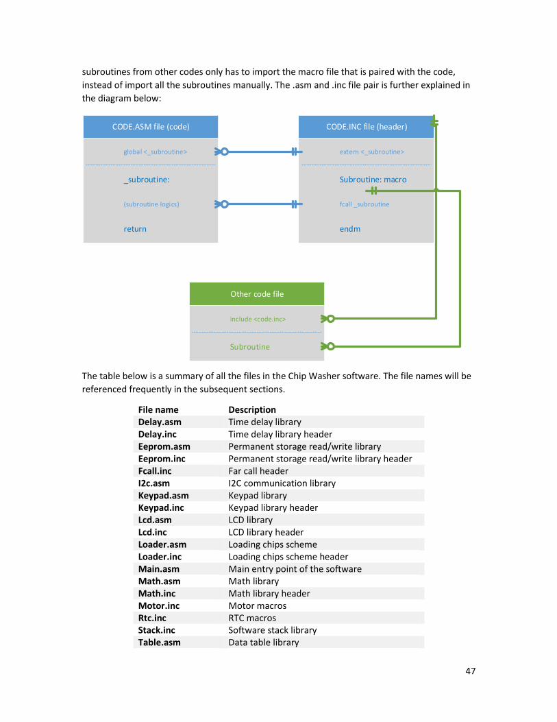
47
subroutines from other codes only has to import the macro file that is paired with the code,
instead of import all the subroutines manually. The .asm and .inc file pair is further explained in
the diagram below:
CODE.ASM file (code) CODE.INC file (header)
Other code file
global <_subroutine>
_subroutine:
(subroutine logics)
return
extern <_subroutine>
Subroutine: macro
fcall _subroutine
endm
include <code.inc>
Subroutine
The table below is a summary of all the files in the Chip Washer software. The file names will be
referenced frequently in the subsequent sections.
File name Description Delay.asm Time delay library Delay.inc Time delay library header Eeprom.asm Permanent storage read/write library Eeprom.inc Permanent storage read/write library header Fcall.inc Far call header I2c.asm I2C communication library Keypad.asm Keypad library Keypad.inc Keypad library header Lcd.asm LCD library Lcd.inc LCD library header Loader.asm Loading chips scheme Loader.inc Loading chips scheme header Main.asm Main entry point of the software Math.asm Math library Math.inc Math library header Motor.inc Motor macros Rtc.inc RTC macros Stack.inc Software stack library Table.asm Data table library

48
Table.inc Data table library header Timer.asm Timer library Timer.inc Timer library header Ui.asm UI lower level library Ui.inc UI lower level library header Ui2.asm UI higher level library Ui2.inc UI higher level library header
7.3.3 PAGING To achieve high code stability, one of the foremost problems to solve is paging of flash memory
and general purpose registers. Paging allows two more bits in the program address by explicitly
store two bits in the general purpose register, thus increase the accessible program memory by
a factor of 4. Chip Washer software uses 80% of the program memory of PIC16F877, consisted
of all four pages of the memory. If paging is not correctly configured, then the software might
malfunction because the program counter might run into a wrong program address and
execute. The solution of paging problem is the utilization of banksel, pagesel, lcall, lgoto
directives from the MPASM compiler, and the creation of fcall macro. Banksel and pagesel
directives calculate the upper bits of the program address and add to the program while during
compiling process. Fcall macro makes sure the page is set back to the current program line when
finishes a call. The actual code of fcall is in <fcall.inc> file.
7.3.4 STACK Chip Washer software achieved very high code efficiency by using modularized subroutines
instead of the use of macro code. One of the issues that come with using subroutines is
parameter passing and result returning. In C programming language or some other high level
programming language, a software stack is often used to pass parameters and result returning.
To solve this issue, Chip Washer software built a software stack for the purpose of parameter
passing and result returning.
The mechanism of a software stack is further explained in the diagram below. Similar to the file
system diagram, the diagram below adds one more layer of call stack and return stack.
Therefore, the other code file does not need to know the local addresses of the file registers
used by the code library; instead, it passes parameters to the stack which is shared by the entire
program. After the execution of the subroutine logics, the results are stored in the return stack
waiting for the retrieval by the caller. The implementation of stack library is in <stack.inc> file.

49
CODE.ASM file (code) CODE.INC file (header)
Other code file
Call Stack
Return Stack
global <_subroutine>
_subroutine:
(subroutine logics)
return
extern <_subroutine>
Subroutine: macro param1, param2
fcall _subroutine
endm
include <code.inc>
Subroutine param1, param2
param1 (0x00)
param2 (0x01)
result1 (0x00)
result2 (0x01)
StackWrite param2
StackWrite param1
StackRead param1
StackRead param2
StackWrite result1
StackWrite result2
StackRead result1
StackRead result2
7.3.5 MATH One of the drawbacks of using PIC16F877 microcontroller is a lack of multiplication/division
arithmetic unit. To compensate this loss of feature, software code of multiplication/division is
needed. To correctly display and parse user data on bottle numbers and timing (Chip Washer
can allow users to enter a maximum of 99 bottles if possible), binary/decimal number

50
conversion must also be implemented. Implementation of features above is implemented in
<math.inc> and <math.asm> files (for binary/decimal conversions, the code is in LCD.asm for
bin-dec and UI.asm for dec-bin). The diagram below explains how to call the functions.
Call Stack for Multiply
Return Stack for Multiply
Call Stack for Divide
Return Stack for Divide
Multiplier A (0x00)
Multiplier B (0x01)
Result (0x00)
Multiplier A (0x01)
Divisor (0x00)
Dividend (0x01)
Quotient (0x00)
Remainder (0x01)
The table below summarizes the memory organization of the math library.
Address Name Description 0x28 _Divisor Divisor parameter to division 0x29 _Dividend Dividend parameter to division 0x2A _Quotient Quotient of the division subroutine 0x2B _Multiplier A First multiplier parameter 0x2C _Multiplier B Second multiplier parameter 0x2D _MultiplyResult Result of the multiplication
7.3.6 DATA TABLE To display various UI messages on the LCD display, data table is needed in the code for more
clear and organized UI data, which is considered good coding practice. Data tables is achieved by
changing the program counter to the address of the data table, each line of which consists a
return argument that returns the element in the data table. Since PIC16F877 has page
constraints, directly calling data table will cause unstable behavior if the data table is not in the
first page or the data table exceeds 256 lines. One way of solving this is to manually check the
location of the data table and change the higher bits in the program counter to ensure that
paging is handled correctly. The table calling is implemented in <table.inc> and <table.asm>.
7.3.7 LCD Major functions of LCD component of the software is to handle low level LCD interface,
including initialize the LCD screen, display single character, shift cursor, turn on/off cursor,
switch line, clear LCD, display a message from any data table, rotate the message, display
current data time, display timing data from the memory. All command that associates with

51
HITACHI 44780 LCD decoder is stored in a macro of #define block on top of <lcd.asm> file.
Display message mechanism is simply a loop calling data tables until the stop token is reached
(for strings, the stop token is 0 character in ASCII). The implementation of the LCD component is
in <lcd.inc> and <lcd.asm>
7.3.8 KEYPAD The keypad component of the software initializes the keypad communication ports, and handles
low level polling and decoding of the keypad input when user input is expected. The keypad
decoding scheme converts the keypad input 4-bit data into ASCII character for LCD display, or
converts into binary number for decimal-binary number conversion. Other schemes defined in
the keypad component waits the user to input through key or simply reads from the current
keypad input value. The implementation of keypad is in <keypad.inc> and <keypad.asm> files.
7.3.9 UI The UI component is one of the higher level component in the software. It combines both
keypad and LCD scheme. It controls the flow of the text output and user input, and provides
prompt response and feedback for user. Because of its complexity, the UI component is split
into two pieces of code pairs: <ui.inc>, <ui2.inc>, <ui.asm>, and <ui2.asm>. Major functionalities
achieved in the UI component are:
1. Validate keystroke
2. Read input for a given number of maximum expected characters and character validator
(general purpose input box)
3. Parse number input
4. Parse pattern input
Each part above will be presented into detail in the subsections under UI.
Major scheme of the UI flow include:
1. Display welcome message
2. Ask user to input total number of containers
3. Let user to choose the pattern for each bottle from a preset menu
4. Let user to customize the pattern by inputting the pattern directly through keypad
5. Display all the patterns chosen for all the containers
6. Ask user to confirm the start of the machine operation
7. Display finish message
The general flow of the UI scheme is illustrated in the diagram below, the major components
will be explained into details in the subsections:

52
Start:Display welcome
messageDisplay current
date/time
Wait user to press any key
Display cancelled message
Prompt user to enter number of
containers
Prompt user to enter the pattern for
the Nth containerMenu router
If all containers patterns entered
Confirm to start
Customize pattern
Start of loading scheme
Finish of loading scheme
Yes
No
7.3.9.1 KEYSTROKE VALIDATION Different keystrokes are expected in different scenarios. For example, when the user is prompt
to enter the number of bottles, it would not make sense to display key input other than 0-9. In
other cases, only A/C keys are expected in the process of pattern customization. A generic
keystroke validator is designed such that a mask will be applied on all key event, and only keys
that are expected will be notified to the microcontroller input scheme. The separation of this
part as an individual functional unit is essential for the construction of a general purpose input
box which is explained in the next subsection.
Since the keypad has a size of 4*4, it needs two 8-bit validators (masks). For example, for
number input, the validator looks like:
Keys B 6 5 4 A 3 2 1 Lower bits masks 0 1 1 1 0 1 1 1 Keys D # 0 * C 9 8 7 Higher bits masks 0 0 1 0 0 1 1 1 For any keystroke, a keystroke byte will be sent to the mask. The construction of the keystroke
byte involves in a bit shifting of 0x1. For example, key A has the fourth order in the lower bits
mask, then 0x01 is shifted to the left for three times, which will result in a 0x08 keystroke byte.
The following table summarizes all the keystroke byte generated by the software:
Key\Bit 7 6 5 4 3 2 1 0 1 0 0 0 0 0 0 0 1 2 0 0 0 0 0 0 1 0 3 0 0 0 0 0 1 0 0 A 0 0 0 0 1 0 0 0 4 0 0 0 1 0 0 0 0 5 0 0 1 0 0 0 0 0

53
6 0 1 0 0 0 0 0 0 B 1 0 0 0 0 0 0 0 7 0 0 0 0 0 0 0 1 8 0 0 0 0 0 0 1 0 9 0 0 0 0 0 1 0 0 C 0 0 0 0 1 0 0 0 * 0 0 0 1 0 0 0 0 0 0 0 1 0 0 0 0 0 # 0 1 0 0 0 0 0 0 D 1 0 0 0 0 0 0 0
For Key 1-B, the keystroke byte will be masked by the lower bits mask, and for Key7-D, the
keystroke byte will be masked by the higher bits mask. If the masked value is not zero, then the
UI will display the keystroke, otherwise, the microcontroller will ignore the keystroke. More
details on passing the validator to the input box will be explained in the next subsection.
7.3.9.2 GENERAL PURPOSE INPUT BOX General purpose input box is useful in all kinds of user interaction scenarios. However,
constructing a generic input box is hard in microcontroller assembly language because it needs
to take into consideration of temporary input stack, key erasing, variable maximum length,
cursor position, and keystroke validation. Thankfully, keystroke validating unit is built to
accommodate the input box. For calling a general purpose input box subroutine, higher-bit
validator and lower-bit validator are expected to be in the call stack at relative address 0x01 and
0x00. Maximum length of the input box must also be specified. The length parameter should
stay in the call stack at relative address 0x02. The input stack will support 10 characters at
maximum, to accommodate the input of customized pattern. However, for other usage of the
input box, an address change will extend the maximum length to any length that is supported by
the memory space. The diagram below illustrates the memory organization of the input box,
including the call stack.
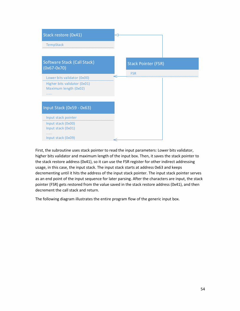
54
Software Stack (Call Stack) (0x67-0x70)
Lower bits validator (0x00)
Higher bits validator (0x01)
Input Stack (0x59 - 0x63)
Input stack pointer
Input stack (0x00)
Maximum length (0x02)......
Input stack (0x01)......Input stack (0x09)
Stack restore (0x41)
TempStack
Stack Pointer (FSR)
FSR
First, the subroutine uses stack pointer to read the input parameters: Lower bits validator,
higher bits validator and maximum length of the input box. Then, it saves the stack pointer to
the stack restore address (0x41), so it can use the FSR register for other indirect addressing
usage, in this case, the input stack. The input stack starts at address 0x63 and keeps
decrementing until it hits the address of the input stack pointer. The input stack pointer serves
as an end point of the input sequence for later parsing. After the characters are input, the stack
pointer (FSR) gets restored from the value saved in the stack restore address (0x41), and then
decrement the call stack and return.
The following diagram illustrates the entire program flow of the generic input box.

55
Detect keypad input
No
Get the input valueGenerate keystroke
byte
Mask with validatorValid keystroke?
Yes
No
Maximum length reached?
Yes
Move stack pointer, move cursor
position to the next
Display character and store in the
input stack
No
Yes
Check value
Start Submit End
# key
If at start of the input stack
Move stack pointer, move cursor
position to the previous
* key
Other keys
Yes
No
The picture below illustrates the actual user interface of the input box. Cursor stays right beside
the last input character. Characters can be erased by hitting “Corr” key at the left bottom. Input
box can be submitted by hitting “OK” key at the bottom.

56
7.3.9.3 INPUT NUMBER PARSING To have a programmable knowledge on the number of bottles entered by the user (assuming
the total number can exceed 9), a decimal-binary number conversion needs to be implemented
in the parsing scheme of the input stage. Thanks to the construction of math library in the
previous subsection, the conversion is not extremely difficult. The following chart illustrates the
flow of parsing a number from the input stack to the parsed input number address (0x64).
Read the current character from the
top of the input stack (hundredth
digit first)
Decode the keystroke into
number
Send the number to multiplication of 10
Add the number to the temporary
number
Reach the end of the stack?
Move the temporary number to parsed number
address
Save the stack pointer
Move the stack pointer to the input
stack
Yes
No

57
7.3.9.4 MENU ROUTING (PATTERN SELECTION) The menu routing scheme is an essential part of the user interaction. The most time spent is for
user to input the patterns. The developer of the software believes that it is not sensible to force
the user to remember the patterns and it will always be helpful to display the pattern on the
user interface to help the user to decide which pattern to load. Restricted by the size of the LCD
screen, only two patterns can be displayed at a time. Hence, a flow loop is designed to help user
browse across all the possible choices. Users can use hot key 1-6 to quickly select between
patterns 1-6 without the need to browse the menu. Table below summarizes the preset
patterns that come with the machine (can be modified using PC interface). Users can definitely
create a pattern imaginatively at any time by hitting hot key 7 to initiate a customized pattern
input. The mechanism of customized pattern includes the input box stage, which is explained
into detail in the previous subsections, and input parsing stage, which will be explained in the
next subsection. The design of the pattern selection scheme demonstrates the effort made to
maximize the user customizability and convenience in software development. The diagram
below illustrates the program flow of the menu routing.
Pattern Number Pattern (A for amber, C for camel) 1 CCCCCCCCCC 2 AAAAAAAAAA 3 CCCCCAAAAA 4 CCAACCAACC 5 AACCAACCAA 6 CACACACACA

58
Wait keystroke
Display Menu 1, 2
Wait keystroke Display Menu 3,4 Wait keystroke
Display Menu 5, 6
Wait keystrokeDisplay Menu 7
Copy the pattern to current pattern
Parse the input pattern
Copy the current pattern to
configuration storage
# key 1-6 key
# key
# key
# key
1-6 key
1-6 key
1-6 key
Customize pattern input
7 key
7 key
7 key7 key
Start
End
7.3.9.5 PATTERN PARSING To accommodate a full feature of customized patterns at runtime, parsing the patterns from the
input stack to the configuration storage is needed. The following diagram gives very good
explanation of mechanism of pattern parsing, which is similar (even simpler) than decimal-
binary number conversion.
Read the current character from the
input stack
Reach the end of the stack?
Move the temporary pattern to parsed pattern
address
Save the stack pointer
Move the stack pointer to the input
stack
Yes
Is character C or A?
No
Set the corresponding bit to
1
Set the corresponding bit to
0C
A
59
7.3.9.6 REAL TIME AND TIMING Real time display and timing component is achieved with DS1907 integrated circuit and the
corresponding socket on DevBugger board. The microcontroller communicates with the RTC
(Real Time Clock) circuit with I2C communication through PORTC pin 3 and 4. The
communication interface is summarized in table below:
Address 0x06 0x05 0x04 0x03 0x02 0x01 0x00 Description Year Month Day Weekday Hour Minute Second
As shown above, memory addresses in RTC chip give date time information. All 8-bit numbers
saved in those addresses are in decimal number format. For the upper four bits are the tenth
digit, and the lower four bits are the ones digit. RTC can be reset through writing values to each
memory addresses in RTC. The implementation of RTC module is in <rtc.inc> and <i2c.asm>.
RTC module is also utilized for timing purpose of the entire machine operation. Upon the start of
the operation, time information is stored in the memory. As the machine operation ends, the
program retrieves time information again. Since time information is stored in decimal format for
each digit, to do a proper subtraction, the software needs to first convert the decimal number in
each digit to a binary number. Carries are also handled in case the end time has second or
minute that is less than the start time. The diagram below illustrates the scheme of timing
module. The implementation of timing module is in <timer.inc>
Table below explains the memory organization of the Timing component.
Address 0x7C 0x7D 0x7E 0x7F Description Temporary
timer count Timer second Timer minute Timer hour
7.3.10 SENSOR AND MOTOR CONTROL Sensor and motor control component of the software are in charge of the entire automatic flow
of loading chips to the containers, adding lids of the containers, counting the remaining chips,
and returning the chips back to the reservoir. In detail, the flow of the machine can be
summarized into the following chart:

60
Loading scheme flow chart
Lid coveringLoadingInitializationBasic motor control Chip counting Chip returningPh
ase
Start
Initialization:Clear/Turn on timer
Display messageClear bottle counter
Write logs
Is the micro-switch hit?
Turn on motor
Turn motor on opposite direction
for small time delay and stop motor
No
Yes
Loading: Load next container
Turn base motor
Read patterns from memory
Is all 10 chips loaded?
Read next chip pattern
Are all containers
loaded
Cover lid: Turn base motor and wait for
lid micro-switch
5 empty passes though the sensor?
Rotate Fin C for small delay to overcome the micro-switch.
Rotate Fin A to previous position
If sensor A is activated
If maximum wait time is reached
No
Rotate Fin A for small delay to overcome the micro-switch.
Rotate Fin C to previous position
Increment chip A count
Yes
Yes
If sensor is activated
If maximum wait time is reached
No
Increment chip C count
Yes
Yes
No
Initialize Lid CoverInitialize Fin A/CRotate to initial
position
Initialize ReservoirRotate back and forth with time
delay to unjam the chips
Turn on motor for small time delay
Turn on motor for opposite direction
for small time delay
Turn off motor
Turn on motor for time delay
Overcome the load micro-switch
Overcome the lid micro-switch
No
Which color to load
Rotate Fin A to next position
Rotate Fin C to next position
Camel
Amber
Re-initialize the reservoir
Yes
No
Yes
Turn lid cover half way
Turn lid cover back half way
Reposition lid cover
Rotate Fin A for next position
Rotate Fin A for next position
If sensor C is activated
If sensor A is activated
If both A and C chips reached 5 empty passes
End
Clear empty pass for A
chips
Clear empty pass for A
chips
End:Stop all motors
Show chip counting information
Finish Machine Logs
Yes
Yes
No
Yes
Yes
No
Yes
No

61
7.3.10.1 INITIALIZATION In the initialization stage, motors including lid cover motor and fin motors get to find with their initial
position by detecting the micro-switches. Once this is done, the reservoirs start the unjam process of
rotating back and forth for several times until the chips are sorted into a line in front of the fins.
7.3.10.2 LOADING The loading stage starts with positioning the container into the right loading site by detecting micro-
switches. By reading the current loading pattern, the software decides which fin wheel to turn to load
the chip of correct colour.
7.3.10.3 LID COVERING After loading the correct pattern for the container, the base wheel continues to turn until the container
enters the lid covering site. The lid cover motor turns half way to cover and snap the lid, and then turns
back to re-position itself.
7.3.10.4 CHIP COUNTING After all containers are loaded and covered, the reservoirs continues to turn but with fins tuning in an
opposite direction. Meanwhile, IR sensors are polled to check the number of chips remaining. This
process continues until five empty passes through the IR sensors are reached.
7.3.10.5 CHIP RETURNING In the end, all remaining chips are returned back into the reservoir by turning reservoir wheel in the
clockwise direction and fin wheel in the counterclockwise direction. This process continues until five
empty passes through the IR sensors are reached.
7.3.10.6 SENSORS Software uses sensor polling instead of interrupt because polling gives maximum flexibility, stability and
maintainability. Time delay is inserted to stabilize polling input.
7.3.10.7 MOTORS Since the mechanical part of the machine uses only DC motors and micro-switches to control the
position, rotating on an opposite direction when the micro-switches are hit is necessary. Therefore,
most DC motor controls are equipped with two output pins, connected through a buffer circuit and
eventually signaling the H-bridges. H-bridge input standards are hence followed, specified in the table
below.
H-bridge (2 pins) 0, 0 0, 1 1, 0 Meaning Stop Counterclockwise Clockwise
The code implementation of the sensor and motor control are in <motor.inc>, <loader.inc>,
<loader.asm> files.
7.3.11 EMERGENCY STOP The software emergency stop is designed to be key “D”. After key “D” is hit during pattern configuration
and machine running, the program will exit and goto address 0x08, which is a reset vector to redirect

62
the program to display “Task cancelled” information on the LCD. After the emergency stop text is
displayed, the program is reset to the start point.
The way of reading emergency stop is still port polling. In any waiting stage (waiting sensor/user input),
polling on key “D” scheme is added so that emergency stop is allowed at this stage. Due to the high
speed of microcontroller operation, it is safe to assume that the keystroke of key “D” will last longer
than any other non-waiting stage of the code, so that the emergency keystroke can always be detected
by the microcontroller.
The software emergency stop is a different concept with the circuit emergency stop. After the circuit
emergency stop is hit, the microcontroller is still operating, which means after re-enabling the
emergency switch, the loading will continue from the previous point. If both emergency stops are hit,
then the loading scheme cannot be restored and the entire program is reset to the start position. The
separation of roles of two types of emergency stops allow user to decide whether a pause or a complete
stop is needed based on specific circumstances.
7.3.12 PERMANENT STORAGE Permanent storage allows the software to store data permanently even if the machine is powered off.
Two important information should be saved in the permanent storage: preset patterns and machine
logs.
<eeprom.inc>, <eeprom.asm> provide basic interface for reading and writing to the permanent storage.
The mechanism of reading and writing to the permanent storage is similar to indirect memory
addressing. Permanent memory address is written into EEADR register, and the value to read/write is
prepared in EEDATA register. EECON1 register controls whether to read or to write to the permanent
storage.
Storing preset pattern menu in the permanent storage gives greatest customizability and convenience
on user operations. Changing the preset menu can be done through PC interface, which will be
explained in the next subsection. Since each pattern contains 10 elements in a sequence (0 for amber
colour, and 1 for camel colour), it will need at least two bytes to store one single pattern. In this
software, only lower 5-bit are used, and two bytes in total to store a single pattern. Higher 3 bits are
remained to be 0. 6 preset patterns will consume 0x0C of the permanent memory, which is read during
menu display.
Permanent logging service is one of the advanced feature in the software. It not only records all the
information of each run, including start date/time, duration of operation, number of containers, pattern
for each container, success/failure of the operation, number of chips left. Permanent storage is utilized
at its maximum efficiency. The logs are at variable length depending on the number of containers, and
continue to write to the permanent storage of the microcontroller until the space are full. The actual
logging service comes with the loading scheme in <loader.asm>. Upon the start of each operation, the
logging service logs the start date/time, number of containers. At the end of each successful container
loading, the service updates the pattern loaded. At the end of a successful operation, the logging service
updates the status of the operation to successful, writes the number of chips left in the reservoir, and
fills the duration time of the operation. Permanent logs can be viewed and downloaded through PC
interface, which gives ultimate support on machine diagnosis.

63
The detail specification of the memory organization of each log is explained in the chart below:
Single Log EntryEEPROM Memory (0x00-0xFF)
Single Pattern (0 for A, 1 for C)
Preset Patterns (0x01-0x0C)
Machine Logs (0x0D-0xFF)
Start Value: 0xFF
Start Time: Year (Tens and Ones in Decimal from RTC)(0BTTTTOOOO)
Start Time: Month (0BTTTTOOOO)
Start Time: Day (0BTTTTOOOO)
Start Time: Hour (0BTTTTOOOO)
Memory Usage Pointer (0x00)
Preset Patterns
Machine Logs
Pattern Higher Bits (0B000PPPPP)
Pattern Lower Bits(0B000PPPPP)
Pattern #1
Pattern #2
Machine Log 1
Machine Log 2
...Machine Log N
...Pattern #6
Start Time: Minute (0BTTTTOOOO)
Start Time: Second (0BTTTTOOOO)
Duration: Minute (Binary)
Duration: Second (Binary)
Success State (S) Container Number (N) (0BSNNNNNNN)
Amber Chips Left (Binary)
Camel Chips Left (Binary)
Pattern 1
...Pattern N
7.3.13 PC INTERFACE PC interface is another advanced feature presented in the software. Two major functionalities are
achieved through PC interface: changing preset pattern menu and download the permanent logs. PC
interface has the ability to write and read from the EEPROM permanent memory of the microcontroller,
and parse the data internally and present friendly information to the users. PC interface is programmed
with C# (.NET technology), which has the most stable support across all Windows platform. PC interface
does not use the RS232 port. Instead, it directly uses USB port, which is more commonly used on

64
electronic devices with PC connectivity features. The PC interface is designed with maximal conciseness
and convenience. The following diagram summarizes the user interaction flow of the PC interface:
Start
Connect USB cable from computer to
the DevBugger
Turn on Programming Mode on the DevBugger
Open ChipWasher.exe
Click Download Button
Preset patterns and Machine Logs are
now downloaded on the screen
Enter the file name of the machine log to save on the local
computer
Click Reset ButtonMachine is now
reset to initial state
Machine log is downloaded to the
computer
Change preset patterns on the left and click Update
Machine preset patterns are
updated
The following picture is the screenshot of the PC interface.
For C# original code of the PC interface, please refer to Appendix.
7.4 IMPROVEMENTS AND SUGGESTIONS The Chip Washer has been made with the belief to perfection. All possible required and additional
features listed in the RFP have been considered and realized. While the space of improvement is
restricted, some suggestions could still be made to the current state of the software.

65
First, if time allowed, it might worth the time to construct an Interrupt Library. Interrupt service is not
used in the software because of its low maintainability and unreliability. But eventually, using interrupt
is a must because one cannot have a program scheme to poll millions of pins at the same time and do
corresponding reaction. Building such a library will made the software programming many times easier
because the entire software can be event-oriented, a classical model that is still widely in use in many
windows-based programs and mobile apps.
Second, although the current PC interface is reliable and usable, one possible improvement is writing a
native program on the microcontroller to send the EEPROM information instead of using the
programmer unit on the DevBugger, which might reduce some of the cost if microcontroller board is
self-made.

66
8 INTEGRATION
8.1 OVERVIEW After the completion of each individual subsystem, integrations are scheduled between the
electromechanical and circuit subsystems, and circuit and microcontroller subsystems. Since the entire
electromechanical subsystem is far behind the total schedule, after a brief test of the functionality of the
communication of all ports, both circuit and microcontroller member joined the process of of building
mechanical components. While building part of the electromechanical subsystem, integration continues
as the circuit boards are temporarily mounted on the machine to test partial functionality. The
integration process was not hugely influenced by the prolonged mechanical components construction
time.
8.2 INTEGRATION BETWEEN CIRCUIT AND ELECTROMECHANICAL COMPONENTS The integration between circuits and electromechanical components includes functionally integrating
sensors into mechanical structures, connecting sensors and motors to the circuit system, securing the
circuit systems on to the mechanical structure, and installing human interface elements which includes
the emergency switch, power switch, and the DevBuger Board.
Due to the prolonged delay in the electromechanical subsystem, sensor integration, which includes the
microswitches and the IR sensors was done at the same time that the mechanical strutures were built
since the electromechanical member and the circuit memeber was working togather. The details of the
integration was already described in the electromechanical section: section 4.2.3 for the fin microswitch,
section 4.2.9 for the base microswitchs, and section 4.2.7 for IR sensor. This model resulted in a few
advanteges. The first advantage is that the mechanical components are now built with the sensors in
mind. This is evident in the design of the fin as the fin and the sensor is integrated perfectly into one
functional system. This increase the overal functionality and the reliability of the sensor. The second
advantage is that the mechanical and electrical system are now tested togather, not only for their
individual function, but also how they work togather. The entire system is then incooperated into the
main system after all tests of integration is complete. This again increases overall reliability and
functionality. Lastly, efficency is greately enhanced, since there is no more taking complete systems
apart to install additional systems. The fin could not have accomplished without the circuit and
electromechanical member working togather like this.
When part of the mechanical components were complete, the circuits system were mounted onto the
machine to test out some functionality. This includes the top resevior layer and the base layer. However,
at that time the circuit panel was not developed and each board was mounted on individually. This
resulted extremely complex and unmanagable wiring, and resulted in the creation of the circuit panel to
house all of the circuits in one place.
Wiring methodolgy for the motors and sensors were already described in the circuit section 5.7. During
the integration, the most time consuming aspect is connecting each wire from the sensors and the
motors to the screw driver terminals. The doube sided circuit panel made the circuits on the inside of
the panel especially diffcult to connect. This is because all of the circuits on the inside are the H-bridges
and all of the H-bridges uses the screw driver terminal to connect with wires. Although the terminals
sound good on paper, they are a pain when used with circuits that located on the inside of the circuit
panel: the tight space made it extremely difficult to insert the stranded wire into the slot of the terminal,

67
and the screw driver often do not have enough space to turn the screw. As result, many screws are not
turned tightly enough and connections often get lost. Thoughts were gave to rectify this situation.
However, the Devbugger board has to be mounted on the outside of the panel and hence, the H-bridges
has to be mounted inside. This is because that is the only way by which all of the boards can be
squeezed on to the circuit panel. Patients were given to try to connect each wire to the terminal as tight
as possible, and care was given to not to distrub the wires to cause loose connections. A better terminal
and a better circuit allocation should be used for future improvements.
The use of the pin to pin wires also caused problems. Wires were often touched and pulled, which
caused the thin metal pin to bend. It turns out the wire pins are fragile to fatigue, and many of the pins
were broken after a few bends. This caused a lot of headaches as the connections between circuits have
to be re-made, which is difficult since many of the connections are on the inside of the already mounted
circuit panel. A better quality pin to pin wire should used for future improvements
8.3 INTEGRATION BETWEEN CIRCUIT AND MICROCONTROLLER 40-pin IDE cable are chosen as the communication wiring between the microcontroller and the rest of
the circuit board because of its simplicity. Output and input test code are programmed on the
microcontroller for debugging purpose (checking connections). In the output test code, all motors are
rotate clockwise, then counterclockwise, and then stop for one second each. This is an effective way to
check whether the motor circuit (voltage and ground) are connected in the correct order. In the input
test code, all the port readings are converted to decimal numbers on the LCD screen to check if the
sensors are connected and active high/low of the sensors are correct.
In the beginning, motor signal decoder is used between the microcontroller and the H-bridges, so that
the direction and enable bits can be separated. But later we found that this configuration is not very
stable, because the circuit cannot with stand float signal, so the microcontroller has to stay on for the
entire time. Later, the decoder circuit is removed and replaced by a buffer circuit which automatically
pulled down the float signal. This allows the microcontroller to be programmed with the rest circuit on,
which significantly enhanced the security of the integration between the microcontroller and the circuit
subsystems.
The microcontroller board is powered by the 5V Vcc and GND port in the 40-pin port, which gives the
maximum simplicity and portability.
During the testing stage, the LEDs that indicate sensor output and motor input were especially helpful.
They helped to debug many circuit and DevBug board connection problems. They also helped to debug
many of the software bugs where the software is sending out the wrong signal or has an unexpected
behavior. It also helped to test the entire system without actual motor operations, which protected the
motors and driver board from damage. The LEDs accelerated the integration and debug process greatly.
8.4 ACCOMPLISHED SCHEDULE The following Gantt chart truthfully represents the actual project progress. It differs much from the
proposed time management schedule mainly on the electromechanical subsystem because of a lack of
realization on the difficulty, and a lack of time awareness. The electromechanical subsystem was able to
finish with the assistance from circuit and microcontroller members, but resulted in a lack of debugging
time, so not enough time was before the public demonstration to find out the problem of the base

68
motor, and no time to substitute the motor. Time management on the electromechanical subsystem is
definitely one area that needs improvement in the future.
ID Task Name Start Finish DurationJan 2013 Feb 2013 Mar 2013 Apr 2013
1/13 1/20 1/27 2/3 2/10 2/17 2/24 3/3 3/10 3/17 3/24 3/31 4/7 4/14
1 64d4/9/20131/10/2013Electromechanical subsystem
2 17d2/1/20131/10/2013Overall design
3 17d2/25/20132/1/2013Reservoir prototyping
4 23d3/5/20132/1/2013Base layer
5 5d3/18/20133/12/2013Frame
11 48d4/9/20132/1/2013Circuit subsystem
21 57d4/9/20131/21/2013Microcontroller subsystem
12 19d3/1/20132/5/2013H-bridges
22 3d2/5/20132/1/2013Pin assignment
23 12d2/5/20131/21/2013Keypad/LCD interface
24 14d2/22/20132/5/2013UI flow
25 2d2/25/20132/22/2013Loading scheme
26 1d2/26/20132/26/2013RTC
28 1d4/8/20134/8/2013PC interface
27 1d4/8/20134/8/2013Permanent log
29 11d3/12/20132/26/2013Integration with circuits
14 4d3/13/20133/8/2013Power board
13 19d3/1/20132/5/2013Sensors
15 1d4/1/20134/1/2013Buffer board
16 9d2/15/20132/5/2013Decoder board
17 3d3/4/20132/28/2013Microcontroller connection board
32d4/1/20132/15/2013Integration between circuits
6 5d3/26/20133/20/2013Reservoir layer 1
7 19d4/5/20133/12/2013Reservoir layer 2
8 21d4/5/20133/8/2013Motor mounting
9 14d4/8/20133/20/2013Sensor mounting
10 7d4/9/20134/1/2013Integration and debugging
30 7d4/9/20134/1/2013Debugging
11d3/12/20132/26/2013Integration with Microcontroller
20 15d4/9/20133/20/2013Integration with Electromechanic
18
19
9 SYSTEM ISSUES AND IMPROVEMENTS Motor is a huge part that affect the success of the machine. The failure in the Public Demonstration was
also largely due to the breakdown of the base motor. First, more realistic calculation on the motor
should have taken place in the planning stage of the project so many mismatch motor testing could be
avoided later in the debugging stage. Second, motors should always be installed on the basis of easy
replacement. The failure of the motor mounting process of one of the reservoir layer has proven this
point. If the base motor had been installed more accessibly, the issue happened in the public
demonstration could have possible been avoided. More work should be done in terms of controlling the
overall motor power. Currently motor power output are controlled directly by placing high power
resistors in series with the motor, which is an inefficient solution in terms of power usage. Gearing is
also worth investigating since if reservoir and base motors are built with high torque, then it will be less
susceptible to the weight of chips, which will improve the motor accuracy for loading chips and less

69
chance of chip jamming in the reservoir. Some chip jamming still occurs at the fin because of lack of
accuracy in controlling the angle of the fin. Since the fin does not need high torque and high power,
servo motor might worth implementing in this case.
More accessible design on the middle reservoir layer might improve the user-friendliness of the machine.
Although currently the reservoir design maximize the accessibility of the chips, but only to the top layer.
For the middle reservoir layer, it is still relatively hard to place chips in and take chips out of the
reservoir. Large design change such as staggered layer design, expandable layer using hinge might worth
trying to improve the accessigbility issue.
PCB circuit is definitely worth implementing on a project scale like this. PCB has advantages such as light
weight, low probability of error, low probability of loose connection, etc. This advantages will push the
project quality and reliability up one level.
If time allowed, it is also great practice to solder another microcontroller board for the purpose of
manufacturing. DevBugger is great board to start with the programming, but once the program solidates,
board that is exclusively made for the machine seems necessary. This will reduce the unnecessary
weight and cost brought by the DevBugger Board.
Lastly, time management has shown to be one of the greatest problem existing in the team. The team
nearly redid most of the mechanical components during the system integration. The delay in the
completion of the mechanical subsystem significantly affected the quality of the integration and
debugging process, which is partially accountable for the failure in the Public Demonstration.

70
10 BUDGET Electromechanical Components
Module Component Unit Price ($)
Quantity Vendor Subtotal ($)
Materials for the entire machine
Sheet wood 5.50 1 Home depot 5.50
Wood stick (round)
2.20 1 Home depot 2.20
Balsa wood stick
1.20 1 Home hardware
1.20
Wood stick (square)
2.20 1 Home depot 2.20
Aluminum sheet
1.00 3 Active Surplus
30
Roller bearing 1.00 8 Active Surplus
80
Lazy Susan bearing
3.50 3 Home Depot 10.50
Nails, screws, nuts, bolts, glue, and steel wire
- - Home Depot 6.00
Reservoir layer, Lid closing
12V 50 rpm DC Motor
13.30 3 Creatron 39.90
Reservoir layer and Base layer
5V 65 rpm DC Motor
7.50 3 Creatron 22.50
Subsystem Total 101.00

71
Cicruits and Microcontroller
Module Component Unit Price ($) Quantity Vendor Subtotal ($)
H- Bridge
TIP 122 0.4 2 DigiKey 0.8
TIP 127 0.4 2 DigiKey 0.8
1k ohm, 1/4 w resistor 0.02 2 Creatron 0.04
100k ohm, 1/4 w resistor 0.02 2 Creatron 0.04
Screw driver terminal 0.5 1 Active surplus
0.5
2N3904 0.16 2 Creatron 0.32
Circuit board 1.2 1 Creatron 1.2
Module subtotal
3.7
six H-bridge total
- - - - 22.2
Buffer board
CD7080 buffer chip 0.8 2 Creatron 1.6
LED 0.05 12 Creatron 0.6
1k ohm, 1/4 w resistor 0.02 12 Creatron 0.24
100 k ohm, 1/4w resistor 0.02 12 Creatron 0.24
Chip seats 0.5 2 1
Circuit board 2 1 Creatron 2
12 pin hole connector 1.4 2 Creatron 2.8
Module subtotal
8.48
Primary Sensor Board
LM358N 1.3 3 Creatron 3.9
1k ohm, 1/4 w resistor 0.02 16 Creatron 0.32
10M ohm, 1/4w resistor 0.02 2 Creatron 0.04
333k ohm, 1/4w resistor 0.02 4 Creatron 0.08
LED 0.05 6 Creatron 0.3
Screw Driver terminal 0.3 6 Active surplus
1.8
6 pin hole connector 1.2 1 Creatron 1.2
Chip seats 0.5 3 Creatron 1.5
Circuit board 2 1 Creatron 2
Module subtotal
11.14

72
Cicruits and Microcontroller Cont.
Secondary Sensor Board
LM358N 2.2 1 Creatron 2.2
1k ohm, 1/4 w resistor 0.02 2 Creatron 0.04
10M ohm, 1/4w resistor 0.02 1 Creatron 0.02
LED 0.05 1 Creatron 0.05
6 pin hole connector 1.2 1 Creatron 1.2
Chip seats 0.5 1 Creatron 0.5
Circuit board 1.5 1 Creatron 1.5
Module subtotal
5.51
Power board
74LS00 0.98 1 Creatron 0.98
AXCOM P2 01222 V23079 Signal relay
1.78 1 Project kit 1.78
78S05 5V voltage regulator
1.2 1 Home hardware
1.2
Toggle switch 1 1 Active surplus
1
68 μF Capacitor 0.3 1 Creatron 0.3
1 μF Capacitor 0.16 3 Creatron 0.48
2N3904 0.16 1 Creatron 0.16
Circuit board 2 1 Creatron 2
LED 0.05 3 Creatron 0.15
Screw Driver terminal 0.3 2 Active surplus
0.6
6 pin hole connector 1.2 2 Active surplus
2.4
Module subtotal
11.05
Signal relay board
IDC 40 pin connector 1.5 1 Creatron 1.5
20 Pin hole connector 2.5 1 Creatron 2.5
Circuit board 1.5 1 Creatron 1.5
Module subtotal
5.5
Power supply connector board
4 Pin power supply connector
2.8 1 Creatron 2.5
DPDT switch 1.5 1 Project kit 1.5
4
Module subtotal
12V , 5V power supply 9.9 1 Active surplus
9.9
DevBug Board 50 1 Project kit 50

73
Cicruits and Microcontroller subsystem total 127.78
System Total 227.58
74
11 CONCLUSION Chip Washer is considered a viable solution with extra design features addressing to the original
problem. Although the public demonstration performance was not satisfactory, the failure was largely
due to the mechanical construction quality but not the design concept. Suggestions are made in the
report for future improvement, which will make the machine more stable and reliable.
Major portion of the report focuses on the design highlight of each subsystem. The design features
highlight the uniqueness and effectiveness of the entire machine. Chip Washer is designed with extra
capacity and features, which consequently increased the difficulty of construction, which the team did
not take in consideration with the previous experience associated with machine building. Many of
mechanical components had to be redone by all three members in the integration stage, which delayed
the entire schedule of project completion. The full debugging process was too late to make large scale
changes to the system, and the base motor, one of the least stable components, broke down during the
public demonstration. Although it was unfortunate about the timing of the motor breaking down, it is an
indicator of lack of stability and reliability of the current prototype machine.
With a wide range of improvement suggestions made in the report, Chip Washer has a future to be fixed
if more time is given. Problems showed up in the Public Demonstration can be solved under the same
machine design. Chip Washer is believed to be the greatest solution to meet the need of the game
company on chip packaging.
12 REFERENCES [1] M.R.Emami, Multidisciplinary Engineering Design: From Theory to Practice, 2013 Ed. New
York NY, McGraw Hill, 2013
[2] Wikipedia contributors. (2013). Backgammon. [Online]. Available:
http://en.wikipedia.org/wiki/Backgammon
[3] Wikipedia contributors. (2013). Packging and labeling. [Online]. Available:
http://en.wikipedia.org/wiki/Packaging_and_labeling

75
13 APPENDIX
13.1 ELECTROMECHANICAL COMPONENTS
13.1.1 LAZY SUSAN BEARING
Name Size Shape Center hole diameter
Normal balancing load capacity
Part Number
Price
4 Lazy 4" Lazy Susan Bearing from Triangle Manufacturing Company
4’’ Square 2.170’’ 300 lbs 4C $2.10 (ebay)
Lazy Susan Blueprint, retrieved Jan. 25, 2010, from http://www.triangleoshkosh.com/assets/files/cad-
drawings-lazy-susans/lazy-susan-4c.pdf

76
13.2 CIRCUITS
13.2.1 SCHEMATICS
13.2.1.1 H-BRIDGE
1 K ohm
TIP 127 TIP 127
PIC Signal, S1
100k ohm 100k ohm
PIC Signal, S0
Ground
5/12 V
TIP 122TIP 122
2N3904
2N3904

77
13.2.1.2 POWER BOARD
LM7805
Common
Power Supply 12V
68 uF Capacitor5 V regulator Sensor and
Micro-controller Power, Line 1
1
Battery Common
Power Supply 5V
IN4003 Power Diode
12 V Motor Power, Line 2
5 V Motor Power, Line 3
Signal Relay
NPN Transistor
1 uF capacitor
Section 1 Voltage regulation
Emergency Stop and Motor Power Control
Toggle switch
13.2.1.3 IR BREAK POINT SENSOR CONTROLLER
Duo IR Emitter LTE 5208A
Green LED
1 Ohm Resistor
Chip Passing
Photo transistor LTR-3208E
10M ohms resistor333k ohms resistor
333k ohms resistor
LM385N duo op amp-
+
1k ohm resistor
Signal indicating LED
To PIC
Regulated 5V
Ground

78
13.2.1.4 MICROSWITCH CONTROLLER
Signal Indicating LED
1k ohm resistor
1k ohm resistor 1k ohm resistor
1k ohm resistor
1k ohm resistor
Micro-switch
+
-
Regulated 5V
Ground
To PIC
LM358N
13.2.1.5 BUFFER
10k ohm resistor1k ohm resistor
Signal indicating LED
To MotorFrom PICCD7050 Buffer Chip
Regulated 5V
Ground

79
13.3 MICROCONTROLLER
13.3.1 GENERAL PURPOSE REGISTER ORGANIZATION Addr File Name Description
0x20 lcd.asm _LcdCommandBuffer Buffer for sending a command to the LCD
0x21 lcd.asm _LcdDataBuffer Buffer for sending data to the LCD
0x22 lcd.asm _LcdNumberPtr Stack pointer to the last digit of the output number
0x23 lcd.asm _LcdNumberChar Output number digit stack (255 max)
0x24 lcd.asm _LcdNumberChar+0x1 Output number digit stack
0x25 lcd.asm _LcdNumberChar+0x2 Output number digit stack (least significant bit)
0x26 lcd.asm _LcdNumberEnd End of the number output stack (constant 0)
0x27 lcd.asm _LcdNumberRemainder Remainder of the number division operation
0x28 math.asm _Divisor Parameter divisor to the Division subroutine
0x29 math.asm _Divident Parameter divident to the Division subroutine
0x2A math.asm _Quotient Return parameter quotient of the Division subroutine
0x2B math.asm _MultiplierA The first multiplier
0x2C math.asm _MultiplierB The second multiplyer
0x2D math.asm _MultiplyResult The multiply result
0x2E table.asm PclTemp Save the program counter higher bits
0x2F loader.asm BottleNumber Total number to bottles
0x30 loader.asm CurrentLoadBottle Currently loading bottle
0x31 loader.asm CurrentLidBottle Currently bottle adding lid
0x32 loader.asm CurrentLoadPatternH Current loading bottle pattern higher
0x33 loader.asm CurrentLoadPatternL Current loading bottle pattern lower
0x34 loader.asm CurrentLoadChip Current loading chip
0x35
0x36
0x37 loader.asm _LoaderChipMask
0x38 loader.asm _LoaderChipMaskCount
0x39 loader.asm _TempSensor
0x3A
0x3B
0x3C
0x3D
0x3E
0x3F
0x40 stack.inc TempW Temporary backup for working register

80
when operating on the stack
0x41 stack.inc TempStack Temporary stack pointer backup for operating on other types of stack other than the default one
0x42 ui.asm TempW Temporary save working register
0x43 ui.asm TempMask Temporary mask by rotating 1
0x44 ui.asm TempCounter Temporary counter for rotating the mask
0x45 loader.asm
0x46 loader.asm
0x47 loader.asm
0x48 loader.asm
0x49 loader.asm
0x4A eeprom.asm Address
0x4B eeprom.asm Value
0x4C keypad.asm Index
0x4D usart.asm TIMCNT
0x4E usart.asm LPCNT
0x4F usart.asm TDATA
0x50
0x51
0x52
0x53
0x54
0x55 delay.inc Counter Counter for number of multiples of delay
0x56 delay.asm d1 Variable for counting the loop
0x57 delay.asm d2 Variable for counting the loop
0x58 ui.asm _UIInputLength Specify the maximum expected length of a given input
0x59 ui.asm _UIInputStackPtr Input stack pointer (the last input character)
0x5A ui.asm _UIInputStack Input stack (10 characters maximum)
0x5B ui.asm _UIInputStack+0x1 Input stack
0x5C ui.asm _UIInputStack+0x2 Input stack
0x5D ui.asm _UIInputStack+0x3 Input stack
0x5E ui.asm _UIInputStack+0x4 Input stack
0x5F ui.asm _UIInputStack+0x5 Input stack
0x60 ui.asm _UIInputStack+0x6 Input stack
0x61 ui.asm _UIInputStack+0x7 Input stack
0x62 ui.asm _UIInputStack+0x8 Input stack
0x63 ui.asm _UIInputStack+0x9 Input stack start
0x64 ui.asm _UIInputNumber The parsed number
0x65 ui.asm _UIInputStackPtrEnd The end of the input stack
0x66 ui.asm _UIInputMax If the maximum input limit is reached

81
0x67 stack.inc StackPtr Stack pointer for passing subroutine parameters, subroutine variable, and subroutine return results
0x68 stack.inc StackPtr Stack pointer for passing subroutine parameters, subroutine variable, and subroutine return results
0x69 stack.inc StackPtr Stack pointer for passing subroutine parameters, subroutine variable, and subroutine return results
0x6A stack.inc StackPtr Stack pointer for passing subroutine parameters, subroutine variable, and subroutine return results
0x6B stack.inc StackPtr Stack pointer for passing subroutine parameters, subroutine variable, and subroutine return results
0x6C stack.inc StackPtr Stack pointer for passing subroutine parameters, subroutine variable, and subroutine return results
0x6D stack.inc StackPtr Stack pointer for passing subroutine parameters, subroutine variable, and subroutine return results
0x6E stack.inc StackPtr Stack pointer for passing subroutine parameters, subroutine variable, and subroutine return results
0x6F stack.inc StackPtr Stack pointer for passing subroutine parameters, subroutine variable, and subroutine return results
0x70 stack.inc StackPtr Stack pointer for passing subroutine parameters, subroutine variable, and subroutine return results
0x71 rtc.inc StackPtr rtc
0x72 rtc.inc StackPtr rtc
0x73 rtc.inc StackPtr rtc
0x74 rtc.inc StackPtr rtc
0x75 rtc.inc StackPtr rtc
0x76 rtc.inc StackPtr rtc
0x77 rtc.inc StackPtr rtc
0x78 rtc.inc StackPtr rtc
0x79 isr.asm WTemp Save the working register temporarily for handling interrupt
0x7A isr.asm StatusTemp Save the Status register temporarily for handling interrupt
0x7B isr.asm PCLATHTemp Save the program counter temporarily for handling interrupt
0x7C timer.asm TimerCount Timer counter from the interrupt. Count every 1/8 second
0x7D timer.asm TimerSec Second part of the counter (59 max)
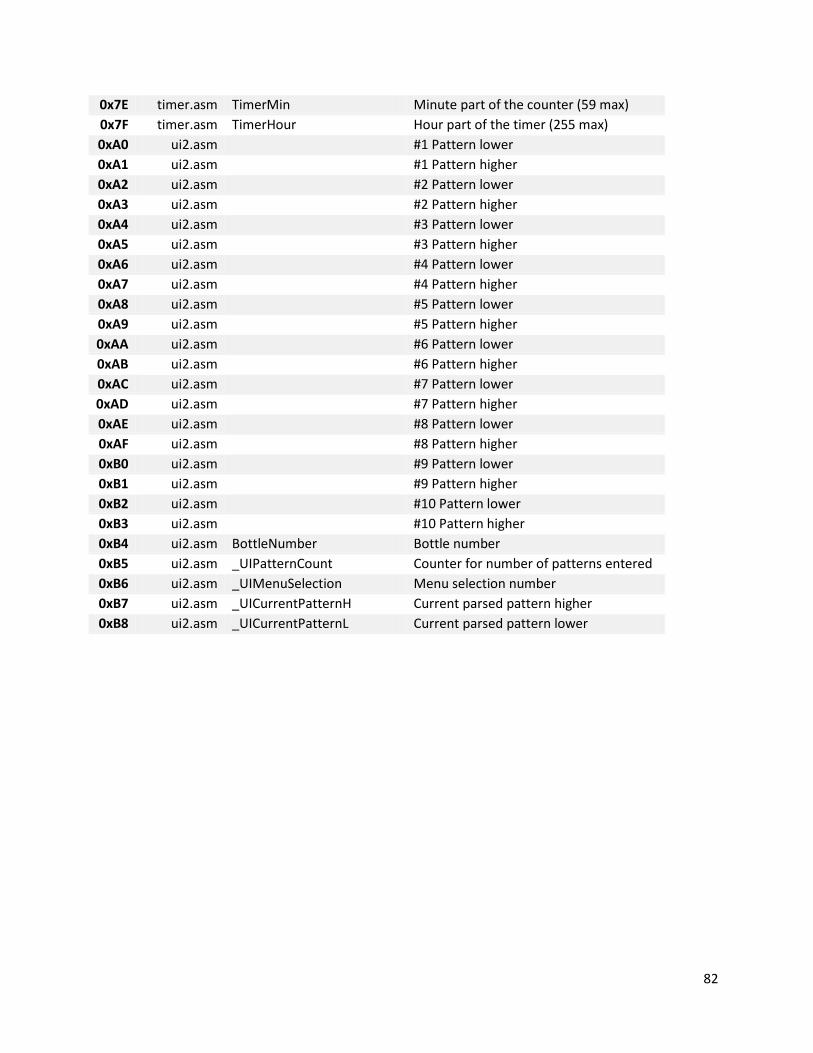
82
0x7E timer.asm TimerMin Minute part of the counter (59 max)
0x7F timer.asm TimerHour Hour part of the timer (255 max)
0xA0 ui2.asm #1 Pattern lower
0xA1 ui2.asm #1 Pattern higher
0xA2 ui2.asm #2 Pattern lower
0xA3 ui2.asm #2 Pattern higher
0xA4 ui2.asm #3 Pattern lower
0xA5 ui2.asm #3 Pattern higher
0xA6 ui2.asm #4 Pattern lower
0xA7 ui2.asm #4 Pattern higher
0xA8 ui2.asm #5 Pattern lower
0xA9 ui2.asm #5 Pattern higher
0xAA ui2.asm #6 Pattern lower
0xAB ui2.asm #6 Pattern higher
0xAC ui2.asm #7 Pattern lower
0xAD ui2.asm #7 Pattern higher
0xAE ui2.asm #8 Pattern lower
0xAF ui2.asm #8 Pattern higher
0xB0 ui2.asm #9 Pattern lower
0xB1 ui2.asm #9 Pattern higher
0xB2 ui2.asm #10 Pattern lower
0xB3 ui2.asm #10 Pattern higher
0xB4 ui2.asm BottleNumber Bottle number
0xB5 ui2.asm _UIPatternCount Counter for number of patterns entered
0xB6 ui2.asm _UIMenuSelection Menu selection number
0xB7 ui2.asm _UICurrentPatternH Current parsed pattern higher
0xB8 ui2.asm _UICurrentPatternL Current parsed pattern lower
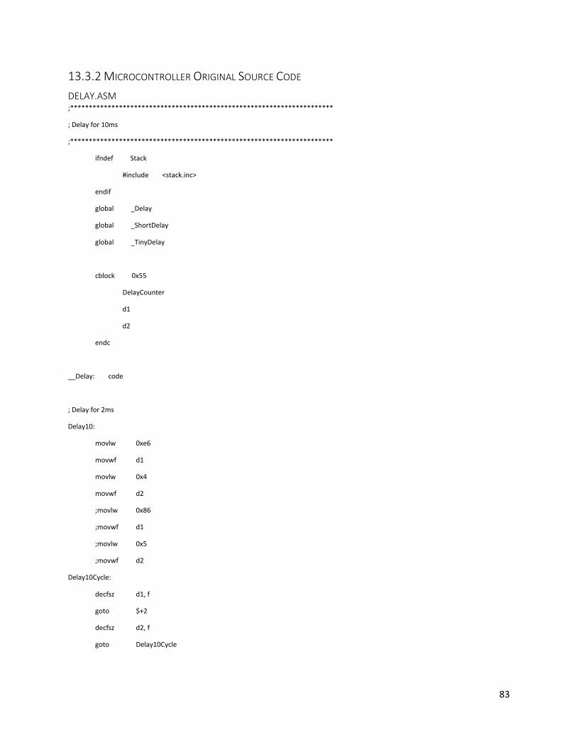
83
13.3.2 MICROCONTROLLER ORIGINAL SOURCE CODE
DELAY.ASM ;**********************************************************************
; Delay for 10ms
;**********************************************************************
ifndef Stack
#include <stack.inc>
endif
global _Delay
global _ShortDelay
global _TinyDelay
cblock 0x55
DelayCounter
d1
d2
endc
__Delay: code
; Delay for 2ms
Delay10:
movlw 0xe6
movwf d1
movlw 0x4
movwf d2
;movlw 0x86
;movwf d1
;movlw 0x5
;movwf d2
Delay10Cycle:
decfsz d1, f
goto $+2
decfsz d2, f
goto Delay10Cycle
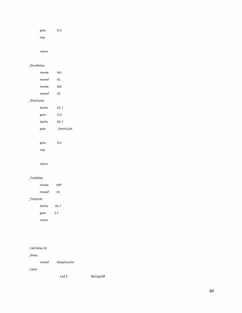
84
goto $+1
nop
return
_ShortDelay:
movlw 0x3
movwf d1
movlw 0x0
movwf d2
_ShortCycle:
decfsz d1, f
goto $+2
decfsz d2, f
goto _ShortCycle
goto $+1
nop
return
_TinyDelay:
movlw 0xff
movwf d1
_TinyCycle:
decfsz d1, f
goto $-1
return
; Call Delay 10
_Delay:
movwf DelayCounter
_Cycle:
call Delay10

85
decfsz DelayCounter, f
goto _Cycle
return
end

86
DELAY.INC ;**********************************************************************
; Delay Library
;**********************************************************************
ifndef Stack
#include <stack.inc>
endif
extern _Delay
extern _ShortDelay
extern _TinyDelay
Delay: macro Time ; multiples of 10 ms
movlw Time
fcall _Delay
endm
;ResWheelPWM: macro Time
; movlw Time
; fcall _ResWheelPWM
; endm
;
;LongResWheelPWM: macro
; ResWheelPWM 0xff
; ResWheelPWM 0xff
; ResWheelPWM 0xff
; ResWheelPWM 0xff
; endm
LongDelay: macro
Delay 0xff
Delay 0xff
Delay 0xff
Delay 0xff
endm

87
ShortDelay: macro
fcall _ShortDelay
endm
TinyDelay: macro
fcall _TinyDelay
endm

88
EEPROM.ASM ;**********************************************************************
; EEProm Library for PIC16
;**********************************************************************
;<editor-fold defaultstate="collapsed" desc="Imports and exports">
ifndef PORTA
#include <p16f877.inc>
endif
ifndef fcall
#include <fcall.inc>
endif
ifndef TinyDelay
#include <delay.inc>
endif
ifndef Pattern1H
#define Pattern1H b'00011111'
#define Pattern1L b'00011111'
#define Pattern2H b'00000000'
#define Pattern2L b'00000000'
#define Pattern3H b'00011111'
#define Pattern3L b'00000000'
#define Pattern4H b'00011001'
#define Pattern4L b'00010011'
#define Pattern5H b'00000110'
#define Pattern5L b'00001100'
#define Pattern6H b'00010101'
#define Pattern6L b'00001010'
endif
global _EEPromWrite
global _EEPromRead
#define _TempEEPtr 0x3b
;</editor-fold>
;<editor-fold defaultstate="collapsed" desc="Variables and constants">
cblock 0x4a

89
Address ; 0x4a
Value ; 0x4b
endc
;</editor-fold>
code
_EEPromWrite:
banksel EECON1
btfsc EECON1, WR ; Wait for
goto $-1 ; write to finish
banksel Address
movfw Address ; Address to
banksel EEADR
movwf EEADR ; write to
banksel Value
movfw Value ; Data to
banksel EEDATA
movwf EEDATA ; write
banksel EECON1
bcf EECON1, EEPGD ;Point to Data memory
BSF EECON1, WREN ;Enable writes
movlw 0x55 ;Write 55h to
movwf EECON2 ;EECON2
movlw 0xaa ;Write AAh to
movwf EECON2 ;EECON2
bsf EECON1, WR ;Start write operation
bcf EECON1, WREN ;Disable writes
banksel PORTA
;TinyDelay
return
_EEPromRead:
banksel Address

90
movfw Address ;Write address
banksel EEADR
movwf EEADR ;to read from
banksel EECON1
bcf EECON1, EEPGD ;Point to Data memory
bsf EECON1, RD ;Start read operation
banksel EEDATA
movfw EEDATA ;W = EEDATA
banksel Value
movwf Value
movfw Value
banksel PORTA
return
end

91
EEPROM.INC ;**********************************************************************
; EEProm Library for PIC16
;**********************************************************************
;<editor-fold defaultstate="collapsed" desc="Imports and exports">
ifndef PORTA
#include <pic16f877.inc>
endif
ifndef _EEPromWrite
extern _EEPromWrite
extern _EEPromRead
endif
#define EEPromAddr 0x4a
#define EEPromValue 0x4b
#define EEPromAddrPtr 0x0
#define EEPromPattern1H 0x1
#define EEPromPattern1L 0x2
#define EEPromPattern2H 0x3
#define EEPromPattern2L 0x4
#define EEPromPattern3H 0x5
#define EEPromPattern3L 0x6
#define EEPromPattern4H 0x7
#define EEPromPattern4L 0x8
#define EEPromPattern5H 0x9
#define EEPromPattern5L 0xa
#define EEPromPattern6H 0xb
#define EEPromPattern6L 0xc
#define Pattern1H b'00011111'
#define Pattern1L b'00011111'
#define Pattern2H b'00000000'
#define Pattern2L b'00000000'
#define Pattern3H b'00011111'
#define Pattern3L b'00000000'
#define Pattern4H b'00011001'

92
#define Pattern4L b'00010011'
#define Pattern5H b'00000110'
#define Pattern5L b'00001100'
#define Pattern6H b'00010101'
#define Pattern6L b'00001010'
;</editor-fold>
EEPromWrite: macro
fcall _EEPromWrite
endm
EEPromRead: macro
fcall _EEPromRead
endm
EEPromReadA: macro Addr
banksel EEPromAddr
movlw Addr
movwf EEPromAddr
fcall _EEPromRead
endm
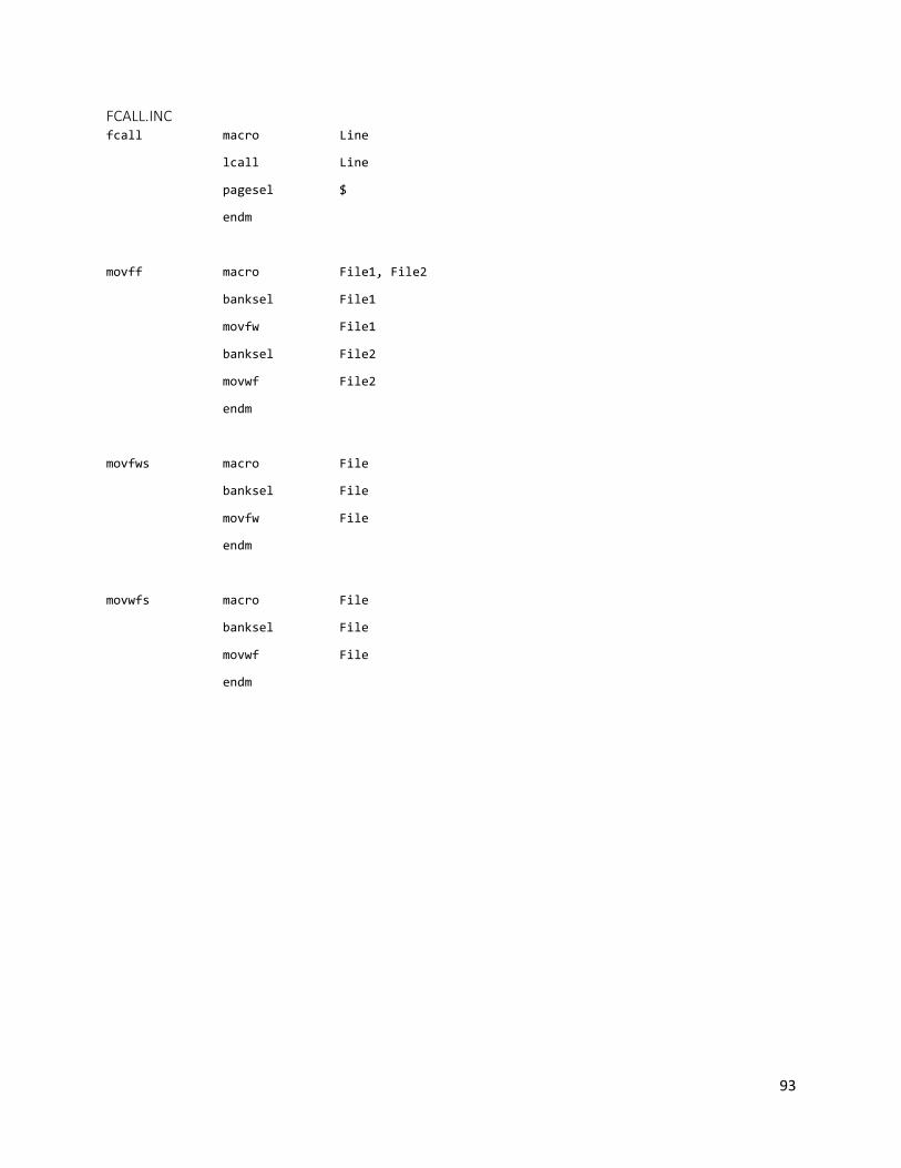
93
FCALL.INC fcall macro Line
lcall Line
pagesel $
endm
movff macro File1, File2
banksel File1
movfw File1
banksel File2
movwf File2
endm
movfws macro File
banksel File
movfw File
endm
movwfs macro File
banksel File
movwf File
endm

94
I2C.ASM include <p16f877.inc>
errorlevel -302
errorlevel -305
;global labels
global write_rtc,read_rtc,rtc_convert,i2c_common_setup,p2p_write,p2p_read
;Definition and variable declarations;;;;;;;;;;;;;;;;;;;;;;;;;;;;;;;;;;;;;;;;;;;;;;;;;
cblock 0x71 ;these variable names are for reference only. The following
dt1 ;0x71 addresses are used for the RTC module
dt2 ;0x72
ADD ;0x73
DAT ;0x74
DOUT ;0x75
B1 ;0x76
dig10 ;0x77
dig1 ;0x78
endc
;I2C lowest layer macros;;;;;;;;;;;;;;;;;;;;;;;;;;;;;;;;;;;;;;;;;;;;;;;;;;;;;;;;;;;;;;
i2c_common_check_ack macro err_address ;If bad ACK bit received, goto err_address
banksel SSPCON2
btfsc SSPCON2,ACKSTAT
goto err_address
endm
i2c_common_start macro
;input: none
;output: none
;desc: initiate start conditionon the bus
banksel SSPCON2
bsf SSPCON2,SEN
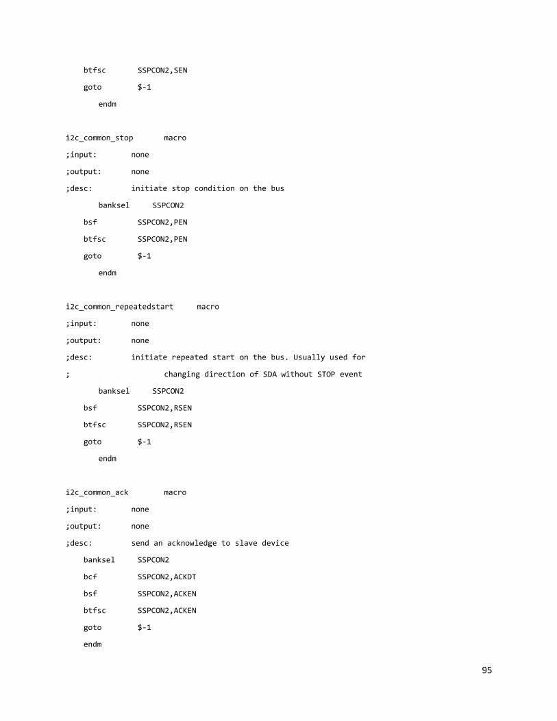
95
btfsc SSPCON2,SEN
goto $-1
endm
i2c_common_stop macro
;input: none
;output: none
;desc: initiate stop condition on the bus
banksel SSPCON2
bsf SSPCON2,PEN
btfsc SSPCON2,PEN
goto $-1
endm
i2c_common_repeatedstart macro
;input: none
;output: none
;desc: initiate repeated start on the bus. Usually used for
; changing direction of SDA without STOP event
banksel SSPCON2
bsf SSPCON2,RSEN
btfsc SSPCON2,RSEN
goto $-1
endm
i2c_common_ack macro
;input: none
;output: none
;desc: send an acknowledge to slave device
banksel SSPCON2
bcf SSPCON2,ACKDT
bsf SSPCON2,ACKEN
btfsc SSPCON2,ACKEN
goto $-1
endm
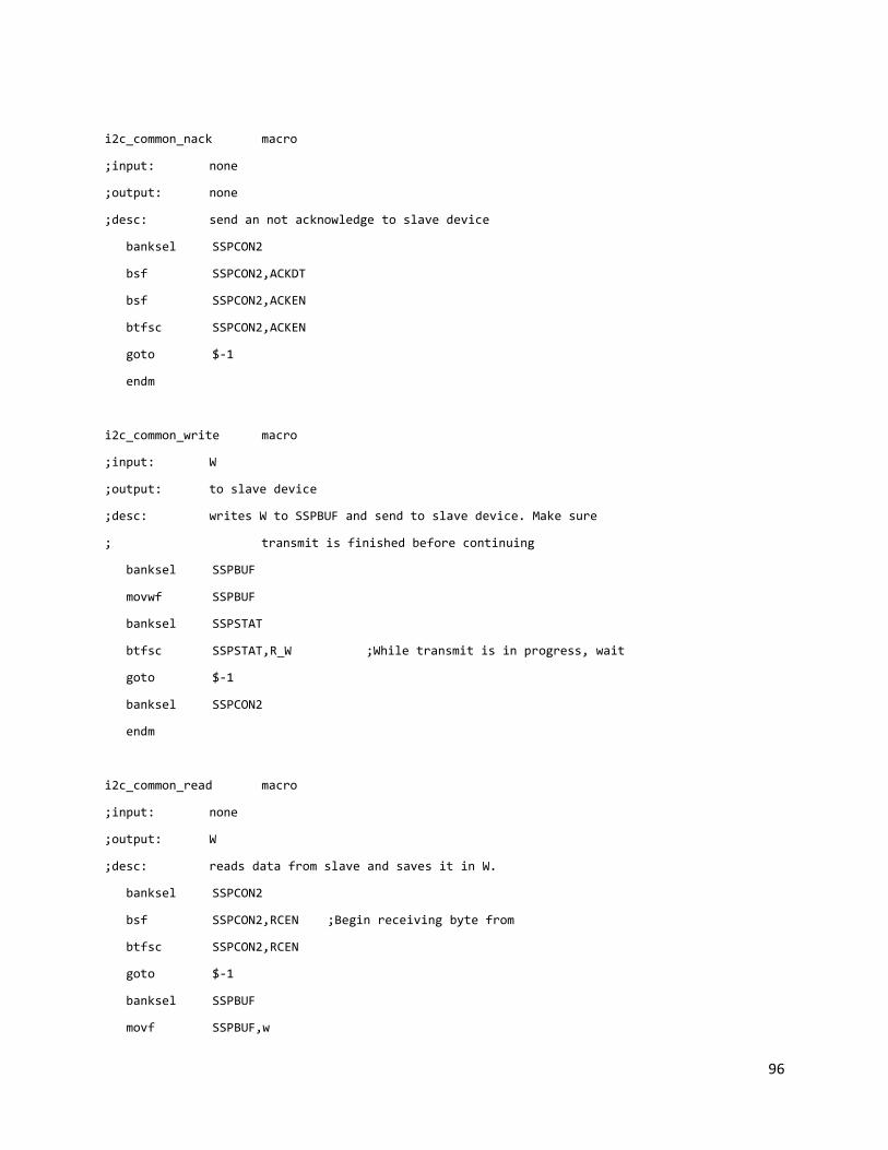
96
i2c_common_nack macro
;input: none
;output: none
;desc: send an not acknowledge to slave device
banksel SSPCON2
bsf SSPCON2,ACKDT
bsf SSPCON2,ACKEN
btfsc SSPCON2,ACKEN
goto $-1
endm
i2c_common_write macro
;input: W
;output: to slave device
;desc: writes W to SSPBUF and send to slave device. Make sure
; transmit is finished before continuing
banksel SSPBUF
movwf SSPBUF
banksel SSPSTAT
btfsc SSPSTAT,R_W ;While transmit is in progress, wait
goto $-1
banksel SSPCON2
endm
i2c_common_read macro
;input: none
;output: W
;desc: reads data from slave and saves it in W.
banksel SSPCON2
bsf SSPCON2,RCEN ;Begin receiving byte from
btfsc SSPCON2,RCEN
goto $-1
banksel SSPBUF
movf SSPBUF,w
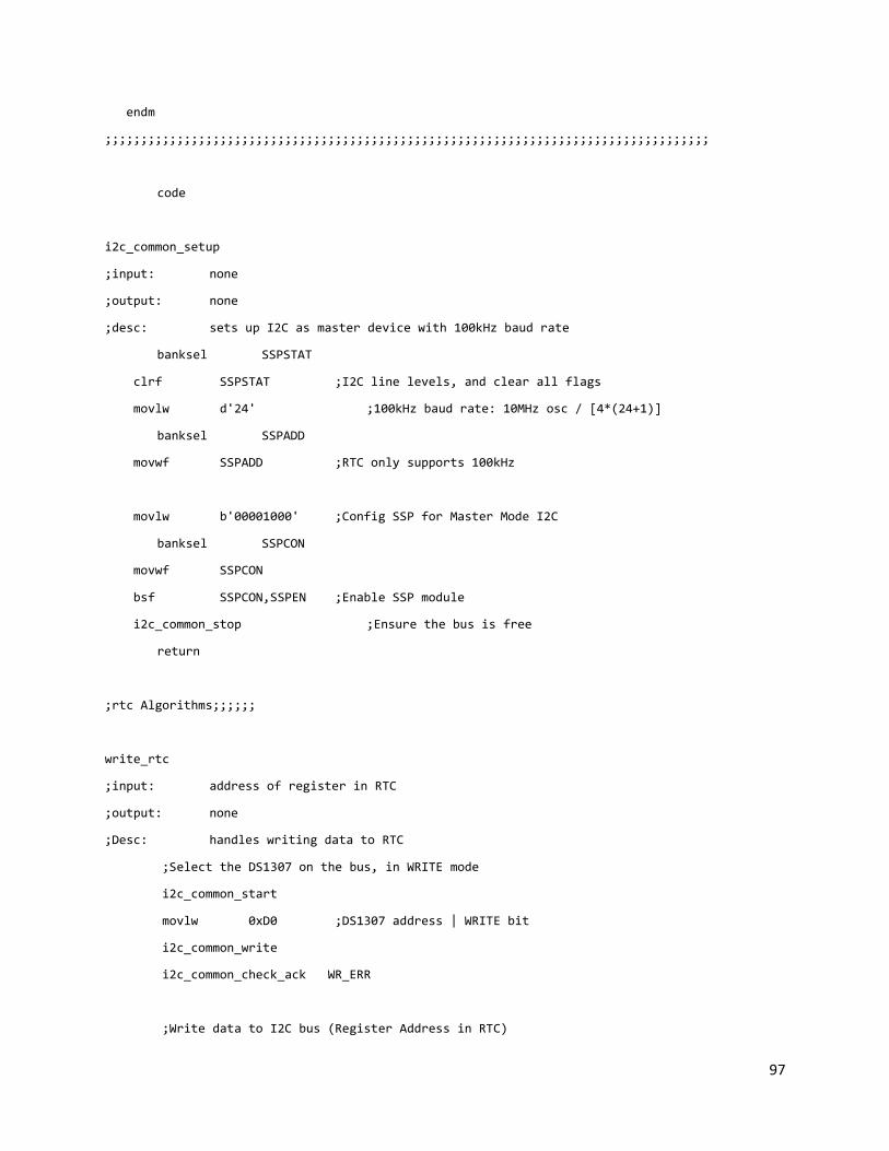
97
endm
;;;;;;;;;;;;;;;;;;;;;;;;;;;;;;;;;;;;;;;;;;;;;;;;;;;;;;;;;;;;;;;;;;;;;;;;;;;;;;;;;;;;
code
i2c_common_setup
;input: none
;output: none
;desc: sets up I2C as master device with 100kHz baud rate
banksel SSPSTAT
clrf SSPSTAT ;I2C line levels, and clear all flags
movlw d'24' ;100kHz baud rate: 10MHz osc / [4*(24+1)]
banksel SSPADD
movwf SSPADD ;RTC only supports 100kHz
movlw b'00001000' ;Config SSP for Master Mode I2C
banksel SSPCON
movwf SSPCON
bsf SSPCON,SSPEN ;Enable SSP module
i2c_common_stop ;Ensure the bus is free
return
;rtc Algorithms;;;;;;
write_rtc
;input: address of register in RTC
;output: none
;Desc: handles writing data to RTC
;Select the DS1307 on the bus, in WRITE mode
i2c_common_start
movlw 0xD0 ;DS1307 address | WRITE bit
i2c_common_write
i2c_common_check_ack WR_ERR
;Write data to I2C bus (Register Address in RTC)

98
banksel 0x73
movf 0x73,w ;Set register pointer in RTC
i2c_common_write
i2c_common_check_ack WR_ERR
;Write data to I2C bus (Data to be placed in RTC register)
banksel 0x74
movf 0x74,w ;Write data to register in RTC
i2c_common_write
i2c_common_check_ack WR_ERR
goto WR_END
WR_ERR
nop
WR_END
i2c_common_stop ;Release the I2C bus
return
read_rtc
;input: address of RTC
;output: DOUT or 0x75
;Desc: This reads from the selected address of the RTC
; and saves it into DOUT or address 0x75
;Select the DS1307 on the bus, in WRITE mode
i2c_common_start
movlw 0xD0 ;DS1307 address | WRITE bit
i2c_common_write
i2c_common_check_ack RD_ERR
;Write data to I2C bus (Register Address in RTC)
banksel 0x73
movf 0x73,w ;Set register pointer in RTC
i2c_common_write
i2c_common_check_ack RD_ERR
;Re-Select the DS1307 on the bus, in READ mode
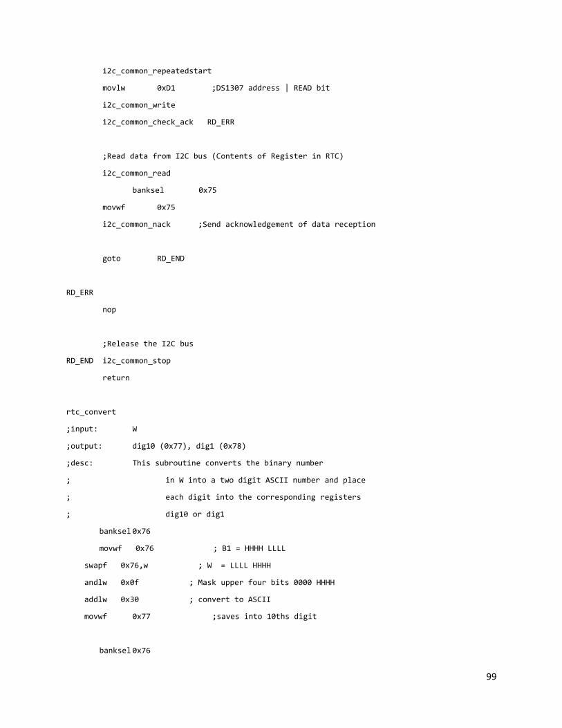
99
i2c_common_repeatedstart
movlw 0xD1 ;DS1307 address | READ bit
i2c_common_write
i2c_common_check_ack RD_ERR
;Read data from I2C bus (Contents of Register in RTC)
i2c_common_read
banksel 0x75
movwf 0x75
i2c_common_nack ;Send acknowledgement of data reception
goto RD_END
RD_ERR
nop
;Release the I2C bus
RD_END i2c_common_stop
return
rtc_convert
;input: W
;output: dig10 (0x77), dig1 (0x78)
;desc: This subroutine converts the binary number
; in W into a two digit ASCII number and place
; each digit into the corresponding registers
; dig10 or dig1
banksel 0x76
movwf 0x76 ; B1 = HHHH LLLL
swapf 0x76,w ; W = LLLL HHHH
andlw 0x0f ; Mask upper four bits 0000 HHHH
addlw 0x30 ; convert to ASCII
movwf 0x77 ;saves into 10ths digit
banksel 0x76

100
movf 0x76,w
andlw 0x0f ; w = 0000 LLLL
addlw 0x30 ; convert to ASCII
movwf 0x78 ; saves into 1s digit
return
;;;;;;;;;;;;;;;;;;;;;;;;;;;;;;
;pic to pic subroutines;;;;;;;;;;;;;;;;;;;;;;;;;;;;;;;;;;;;;;;;;;
p2p_write
;Select the DS1307 on the bus, in WRITE mode
i2c_common_start
movlw b'00010000'
i2c_common_write
i2c_common_check_ack W_END
banksel 0x70
movf 0x70, W
i2c_common_write
i2c_common_check_ack W_END
goto W_END
W_END
i2c_common_stop ;Release the I2C bus
return
p2p_read
;Select the DS1307 on the bus, in WRITE mode
i2c_common_start
movlw b'00010001'
i2c_common_write
i2c_common_check_ack R_END
i2c_common_read
banksel 0x70

101
movwf 0x70
i2c_common_nack ;Send acknowledgement of data reception
R_END
i2c_common_stop
return
;;;;;;;;;;;;;;;;;;;;;;;;;;;;;;;;;;;;;;;;;;;;;;;;;;;;;;;;;;;;;;;;;;;;
End

102
KEYPAD.ASM ;**********************************************************************
; Keypad Library for PIC16
;**********************************************************************
;<editor-fold defaultstate="collapsed" desc="Imports and exports">
ifndef PORTA
#include <p16f877.inc>
endif
ifndef fcall
#include <fcall.inc>
endif
ifndef Delay
#include <delay.inc> ; delay
endif
ifndef StackInit
#include <stack.inc> ; stack
endif
global _KeypadInit
global _KeypadDecode
global _KeypadDecodeNumber
global _KeypadReadChar
global _KeypadWaitChar
#define Index 0x4c
;</editor-fold>
_Keypad: code
;<editor-fold defaultstate="collapsed" desc="_KeypadInit: Initialize the keypad">
_KeypadInit:
banksel TRISA
movlw b'11110010'
movwf TRISB

103
return;</editor-fold>
;<editor-fold defaultstate="collapsed" desc="_KeypadDecode: Decode lookup table">
_KeypadDecode:
;dt "123A456B789C*0#D", 0
banksel Index
movfw Index
sublw 0x0
btfsc STATUS, Z
retlw '1'
movfw Index
sublw 0x1
btfsc STATUS, Z
retlw '2'
movfw Index
sublw 0x2
btfsc STATUS, Z
retlw '3'
movfw Index
sublw 0x3
btfsc STATUS, Z
retlw 'A'
movfw Index
sublw 0x4
btfsc STATUS, Z
retlw '4'
movfw Index
sublw 0x5
btfsc STATUS, Z
104
retlw '5'
movfw Index
sublw 0x6
btfsc STATUS, Z
retlw '6'
movfw Index
sublw 0x7
btfsc STATUS, Z
retlw 'B'
movfw Index
sublw 0x8
btfsc STATUS, Z
retlw '7'
movfw Index
sublw 0x9
btfsc STATUS, Z
retlw '8'
movfw Index
sublw 0xa
btfsc STATUS, Z
retlw '9'
movfw Index
sublw 0xb
btfsc STATUS, Z
retlw 'C'
retlw 0x0
;</editor-fold>

105
;<editor-fold defaultstate="collapsed" desc="_KeypadDecodeNumber: Decode number lookup table">
_KeypadDecodeNumber:
banksel Index
movfw Index
sublw 0x0
btfsc STATUS, Z
retlw 0x1
movfw Index
sublw 0x1
btfsc STATUS, Z
retlw 0x2
movfw Index
sublw 0x2
btfsc STATUS, Z
retlw 0x3
movfw Index
sublw 0x4
btfsc STATUS, Z
retlw 0x4
movfw Index
sublw 0x5
btfsc STATUS, Z
retlw 0x5
movfw Index
sublw 0x6
btfsc STATUS, Z
retlw 0x6
movfw Index
sublw 0x8

106
btfsc STATUS, Z
retlw 0x7
movfw Index
sublw 0x9
btfsc STATUS, Z
retlw 0x8
movfw Index
sublw 0xa
btfsc STATUS, Z
retlw 0x9
retlw 0x0;</editor-fold>
;<editor-fold defaultstate="collapsed" desc="_KeypadReadChar: Poll keypad value from PORTB to W">
_KeypadReadChar:
banksel PORTB
swapf PORTB, w
andlw 0x0f
return;</editor-fold>
;<editor-fold defaultstate="collapsed" desc="_KeypadWaitChar: Wait until a key is hit from keypad">
_KeypadWaitChar:
;goto $
banksel PORTB
btfss PORTB, 1 ;Wait until data is available from the keypad
goto $-1
;Delay d'3'
swapf PORTB, w
andlw 0x0f
;call _KeypadReadChar

107
;banksel PORTB
btfsc PORTB, 1 ;Wait until key is released
goto $-1
return;</editor-fold>
end

108
KEYPAD.INC ;**********************************************************************
; Keypad Library
;**********************************************************************
;<editor-fold defaultstate="collapsed" desc="Imports">
ifndef _KeypadInit
extern _KeypadInit
extern _KeypadDecode
extern _KeypadDecodeNumber
extern _KeypadReadChar
extern _KeypadWaitChar
endif
ifndef PORTA
#include <p16f877.inc>
endif
ifndef TableLookup
#include <table.inc>
endif;</editor-fold>
;<editor-fold defaultstate="collapsed" desc="CheckKey">
CheckKey: macro Key, IfTrue
local IfTrueInit, CheckKeyEnd
addlw -Key
btfsc STATUS, Z
goto IfTrueInit
goto CheckKeyEnd
IfTrueInit:
lgoto IfTrue
CheckKeyEnd:
addlw Key
endm
;</editor-fold>
;<editor-fold defaultstate="collapsed" desc="Check emergency stop">

109
CheckStop: macro
local Check
btfsc PORTB, 1
goto Check
goto CheckStopEnd
Check:
KeypadReadChar
CheckKey 0xf, 0x008
CheckStopEnd:
endm
;</editor-fold>
KeypadInit: macro
fcall _KeypadInit
endm
KeypadReadChar: macro
fcall _KeypadReadChar
endm
KeypadWaitChar: macro
fcall _KeypadWaitChar
endm
KeypadDecode: macro Index
; StackPushL HIGH _KeypadDecode
; StackPushL LOW _KeypadDecode
; StackInc
; StackWriteF 0x0, Index
; TableLookupHL
; StackDec 0x3
; TableLookup _KeypadDecode, Index
movff Index, 0x4c
fcall _KeypadDecode
endm

110
KeypadDecodeNumber: macro Index
; StackPushL HIGH _KeypadDecodeNumber
; StackPushL LOW _KeypadDecodeNumber
; StackInc
; StackWriteF 0x0, Index
; TableLookupHL
; StackDec 0x3
; TableLookup _KeypadDecodeNumber, Index
movff Index, 0x4c
fcall _KeypadDecodeNumber
endm

111
LCD.ASM ;**********************************************************************
; LCD Library for PIC16
;**********************************************************************
;<editor-fold defaultstate="collapsed" desc="Imports, exports and constants">
global _LcdInit
global _LcdWriteData
global _LcdWriteCommand
global _LcdSwitchLine
global _LcdClear
global _LcdRotateLeft
global _LcdHome
global _LcdCursorOn
global _LcdCursorOff
global _LcdDisplay
global _LcdRotate
global _LcdRotateN
global _LcdDisplayNumber
global _LcdDisplayTime
global _LcdCursorLeft
global _LcdCursorRight
global _LcdDisplayDateTime
global _LcdDisplayDate
#define _LcdRs PORTD, 2
#define _LcdEnable PORTD, 3
#define _LcdCommandClear b'00000001'
#define _LcdCommandSwitchLine b'11000000'
#define _LcdCommandShiftLeft b'00011000'
#define _LcdCommandCursorLeft b'00010000'
#define _LcdCommandCursorRight b'00010100'
#define _LcdCommandCursorHome b'00000010'
#define _LcdCommandCursorOn b'00001111'
#define _LcdCommandCursorOff b'00001100'

112
ifndef PORTA
#include <p16f877.inc> ; processor specific variable definitions
endif
ifndef fcall
#include <fcall.inc>
endif
ifndef TableLookup
#include <table.inc>
endif
ifndef Stack
#include <stack.inc> ; lcd constants
endif
ifndef Delay
#include <delay.inc> ; lcd constants
endif
ifndef Divide
#include <math.inc> ; math library
endif
ifndef TimerSec
#include <timer.inc> ; math library
endif
ifndef rtc_read
#include <rtc.inc>
endif
cblock 0x20
_LcdCommandBuffer ; 0x20: Buffer for instruction
_LcdDataBuffer ; 0x21: Buffer for LcdData
_LcdNumberPtr ; 0x22
_LcdNumberChar:0x3 ; 0x23,24,25
_LcdNumberEnd ; 0x26
_LcdNumberRemainder ; 0x27
endc
;</editor-fold>

113
_Lcd: code
;<editor-fold defaultstate="collapsed" desc="_LcdInit: Initialize LCD">
_LcdInit:
Delay 0x01
Delay 0x01
movlw b'00110011' ; First two 0011 sequences
fcall _LcdWriteCommand ; (Display sends two 4-bit chunks)
movlw b'00110010' ; Third 0011 sequence, then set to 4-bit
fcall _LcdWriteCommand
movlw b'00101100' ; 4 bits, 2 lines, 5x7 dots
fcall _LcdWriteCommand
movlw _LcdCommandClear
fcall _LcdWriteCommand
movlw b'00001100' ; Display on/off
fcall _LcdWriteCommand
movlw b'00000110' ; No auto shift left
fcall _LcdWriteCommand
clrf _LcdNumberEnd
return
;</editor-fold>
;<editor-fold defaultstate="collapsed" desc="_LcdStartWrite: Start to write a command">
_LcdStartWrite:
banksel PORTD
bsf _LcdEnable
Delay 0x01
bcf _LcdEnable
;Delay 0x01
return;</editor-fold>
;<editor-fold defaultstate="collapsed" desc="_LcdWriteCommand: Write a command to LCD">
_LcdWriteCommand:

114
bcf _LcdRs ; Clear LcdRs
movwf _LcdCommandBuffer ; Instruction now has the value in the working register
andlw 0xf0 ; Mask 4 bits of most significant bits
banksel PORTD
movwf PORTD ; Send 4 bits most significant bits command
fcall _LcdStartWrite
swapf _LcdCommandBuffer, w ; Swap least significant bits to most significant bits
andlw 0xf0
banksel PORTD
movwf PORTD ; Send least significant
fcall _LcdStartWrite
return
;</editor-fold>
;<editor-fold defaultstate="collapsed" desc="_LcdWriteData: Write LcdData to LCD">
_LcdWriteData:
bsf _LcdRs
movwf _LcdDataBuffer ; Copy the working register to LcdDataa register
movf _LcdDataBuffer, w
andlw 0xf0 ; Get the higher bits
addlw 4 ; Add working register with 100
banksel PORTD
movwf PORTD ; Send working register to Port D
fcall _LcdStartWrite
swapf _LcdDataBuffer, w ; Swap least significant bits to most significant bits
andlw 0xf0
addlw 4
banksel PORTD

115
movwf PORTD
fcall _LcdStartWrite
return
;</editor-fold>
;<editor-fold defaultstate="collapsed" desc="_LcdDisplay: Display a message on LCD">
_LcdDisplay:
StackPush Counter, 0x0
_LcdDisplayCharacterLoop:
TableLookupHL
xorlw b'00000000' ; Check work register to see if 0 is returned (reached the end of the string)
btfsc STATUS, Z
goto _LcdDisplayCharacterLoopEnd
fcall _LcdWriteData
incf Counter, f
goto _LcdDisplayCharacterLoop
_LcdDisplayCharacterLoopEnd:
StackDec 0x01
return;</editor-fold>
;<editor-fold defaultstate="collapsed" desc="_LcdDisplayNumber: Display a decimal number on the LCD">
_LcdDisplayNumber:
StackPushW Number1
StackPushW Number2
StackPushL 0xa
movlw _LcdNumberEnd
movwf _LcdNumberPtr
clrf _LcdNumberEnd
; Get each digit in the number
_LcdDisplayNumberLoop:
Divide
StackReadF Remainder, _LcdNumberRemainder

116
; Save the remainder in the number char array
StackSave
decf _LcdNumberPtr, f
movfw _LcdNumberPtr
movwf StackPtr
movfw _LcdNumberRemainder
addlw d'48'
movwf Stack
StackRestore
; Check if the quotient is zero
StackReadW Quotient
xorlw b'00000000'
btfsc STATUS, Z
goto _LcdDisplayNumberLoopEnd
; Swap the quotient as the new divident
StackReadW Quotient
StackWriteW Divident
StackWriteL Divisor, 0xa
goto _LcdDisplayNumberLoop
; Display the char string to the LCD
_LcdDisplayNumberLoopEnd:
StackSave
movfw _LcdNumberPtr
movwf StackPtr
_LcdDisplayNumberLoopEnd2:
movfw Stack
xorlw b'00000000'
btfsc STATUS, Z
goto _LcdDisplayNumberLoopEnd3
movfw Stack

117
fcall _LcdWriteData
incf StackPtr, f
goto _LcdDisplayNumberLoopEnd2
_LcdDisplayNumberLoopEnd3:
StackRestore
StackDec 0x3
return;</editor-fold>
;<editor-fold defaultstate="collapsed" desc="_LcdDisplayTime: Display time string">
_LcdDisplayTime:
; Process Hour
movlw 0xa
subwf TimerHour, w
btfsc STATUS, C
goto Next1
AddZero1:
movlw d'48'
fcall _LcdWriteData
Next1:
movfw TimerHour
fcall _LcdDisplayNumber
movlw 0x3a ; colon
fcall _LcdWriteData
; Process Minute
movlw 0xa
subwf TimerMin, w
btfsc STATUS, C
goto Next2
AddZero2:
movlw d'48'
fcall _LcdWriteData
Next2:
movfw TimerMin
fcall _LcdDisplayNumber

118
movlw 0x3a ; colon
fcall _LcdWriteData
; Process Second
movlw 0xa
subwf TimerSec, w
btfsc STATUS, C
goto Next3
AddZero3:
movlw d'48'
fcall _LcdWriteData
Next3:
movfw TimerSec
fcall _LcdDisplayNumber
return;</editor-fold>
;<editor-fold defaultstate="collapsed" desc="_LcdDisplayDateTime: display date time">
_LcdDisplayDateTime:
rtc_read 0x06 ;Read Address 0x06 from DS1307---year
movfw 0x77
fcall _LcdWriteData
movfw 0x78
fcall _LcdWriteData
movlw "/"
fcall _LcdWriteData
;Get month
rtc_read 0x05 ;Read Address 0x05 from DS1307---month
movfw 0x77
fcall _LcdWriteData
movfw 0x78
fcall _LcdWriteData

119
movlw "/"
fcall _LcdWriteData
;Get day
rtc_read 0x04 ;Read Address 0x04 from DS1307---day
movfw 0x77
fcall _LcdWriteData
movfw 0x78
fcall _LcdWriteData
movlw " "
fcall _LcdWriteData
;Get hour
rtc_read 0x02 ;Read Address 0x02 from DS1307---hour
movfw 0x77
fcall _LcdWriteData
movfw 0x78
fcall _LcdWriteData
movlw ":"
fcall _LcdWriteData
;Get minute
rtc_read 0x01 ;Read Address 0x01 from DS1307---min
movfw 0x77
fcall _LcdWriteData
movfw 0x78
fcall _LcdWriteData
return;</editor-fold>
;<editor-fold defaultstate="collapsed" desc="_LcdDisplayDate: display date">
_LcdDisplayDate:
; Get year
movlw "2" ;First line shows 20**/**/**

120
fcall _LcdWriteData
movlw "0"
fcall _LcdWriteData
rtc_read 0x06 ;Read Address 0x06 from DS1307---year
movfw 0x77
fcall _LcdWriteData
movfw 0x78
fcall _LcdWriteData
movlw "/"
fcall _LcdWriteData
;Get month
rtc_read 0x05 ;Read Address 0x05 from DS1307---month
movfw 0x77
fcall _LcdWriteData
movfw 0x78
fcall _LcdWriteData
movlw "/"
fcall _LcdWriteData
;Get day
rtc_read 0x04 ;Read Address 0x04 from DS1307---day
movfw 0x77
fcall _LcdWriteData
movfw 0x78
fcall _LcdWriteData
return;</editor-fold>
;<editor-fold defaultstate="collapsed" desc="_LcdRotate: Rotate until the entire message is displayed">
_LcdRotate:
StackPush Counter, 0x0

121
_LcdRotateCharacterLoop:
TableLookupHL
xorlw b'00000000' ; Check work register to see if 0 is returned (reached the end of the string)
btfsc STATUS, Z
goto _LcdRotateCharacterLoopEnd
fcall _LcdRotateLeft
Delay 0x1f
incf Counter, f
goto _LcdRotateCharacterLoop
_LcdRotateCharacterLoopEnd:
fcall _LcdHome
StackDec 0x01
return;</editor-fold>
;<editor-fold defaultstate="collapsed" desc="_LcdRotateN: Rotate N spot">
_LcdRotateN:
movfw Stack
StackPushW Number
_LcdRotateNCharacterLoop:
movfw Number
xorlw b'00000000'
btfsc STATUS, Z
goto _LcdRotateNCharacterLoopEnd
fcall _LcdRotateLeft
Delay 0x8f
decf Number, f
goto _LcdRotateNCharacterLoop
_LcdRotateNCharacterLoopEnd:
StackDec 0x01
return;</editor-fold>
;<editor-fold defaultstate="collapsed" desc="_Lcd: LCD Utilities">
_LcdSwitchLine:
movlw _LcdCommandCursorHome

122
fcall _LcdWriteCommand
movlw _LcdCommandSwitchLine
fcall _LcdWriteCommand
return
_LcdClear:
movlw _LcdCommandClear
fcall _LcdWriteCommand
return
_LcdRotateLeft:
movlw _LcdCommandShiftLeft
fcall _LcdWriteCommand
return
_LcdHome:
movlw _LcdCommandCursorHome
fcall _LcdWriteCommand
return
_LcdCursorOn:
movlw _LcdCommandCursorOn
fcall _LcdWriteCommand
return
_LcdCursorOff:
movlw _LcdCommandCursorOff
fcall _LcdWriteCommand
return
_LcdCursorLeft:
movlw _LcdCommandCursorLeft
fcall _LcdWriteCommand
return
_LcdCursorRight:

123
movlw _LcdCommandCursorRight
fcall _LcdWriteCommand
return
;</editor-fold>
End
124
LCD.INC ;**********************************************************************
; LCD Library for PIC16
;**********************************************************************
;<editor-fold defaultstate="collapsed" desc="Imports and exports">
ifndef PORTA
#include <p16f877.inc>
endif
ifndef fcall
#include <fcall.inc>
endif
ifndef TableLookup
#include <table.inc>
endif
ifndef StackInit
#include <stack.inc>
endif
ifndef _LcdWriteData
extern _LcdWriteData
extern _LcdWriteCommand
extern _LcdSwitchLine
extern _LcdClear
extern _LcdRotateLeft
extern _LcdHome
extern _LcdCursorOn
extern _LcdCursorOff
extern _LcdDisplay
extern _LcdRotate
extern _LcdRotateN
extern _LcdDisplayNumber
extern _LcdDisplayTime
extern _LcdCursorLeft
extern _LcdCursorRight
extern _LcdDisplayDateTime
extern _LcdDisplayDate
125
endif
ifndef _LcdInit
extern _LcdInit
endif
ifndef Delay
#include <delay.inc> ; delay
endif;</editor-fold>
;<editor-fold defaultstate="collapsed" desc="LcdDisplay: Display a message on LCD">
LcdDisplay: macro Message
StackPushL HIGH Message
StackPushL LOW Message
fcall _LcdDisplay
StackDec 0x02
; movlw HIGH Message
; StackPushW HighBits
; movlw LOW Message
; StackPushW LowBits
; lcall _LcdDisplay
; StackDec 0x02
endm;</editor-fold>
;<editor-fold defaultstate="collapsed" desc="LcdDisplayW: Display W value on LCD">
LcdDisplayW: macro
fcall _LcdWriteData
endm;</editor-fold>
;<editor-fold defaultstate="collapsed" desc="LcdDisplayNumber: Display a decimal number on LCD">
LcdDisplayNumber: macro
fcall _LcdDisplayNumber
endm;</editor-fold>
;<editor-fold defaultstate="collapsed" desc="LcdDisplayTime: Display the time string">
LcdDisplayTime: macro

126
fcall _LcdDisplayTime
endm;</editor-fold>
;<editor-fold defaultstate="collapsed" desc="_LcdDisplayDateTime">
LcdDisplayDateTime: macro
fcall _LcdDisplayDateTime
endm;</editor-fold>
;<editor-fold defaultstate="collapsed" desc="_LcdDisplayDateTime">
LcdDisplayDate: macro
fcall _LcdDisplayDate
endm;</editor-fold>
;<editor-fold defaultstate="collapsed" desc="LcdRotate: Rotate until the entire message is displayed">
LcdRotate: macro Message
movlw HIGH Message
StackPushW HighBits
movlw LOW Message
StackPushW LowBits
fcall _LcdRotate
StackDec 0x02
endm
;</editor-fold>
;<editor-fold defaultstate="collapsed" desc="LcdRotateN: Rotate N spot">
LcdRotateN: macro Number
StackPush number, Number
fcall _LcdRotateN
StackDec 0x01
endm;</editor-fold>
;<editor-fold defaultstate="collapsed" desc="LcdDisplayAll: Display a message with shift left number">
LcdDisplayAll: macro Message, Number

127
LcdDisplay Message
LcdRotateN Number
endm;</editor-fold>
;<editor-fold defaultstate="collapsed" desc="Lcd Utilities">
LcdInit: macro
fcall _LcdInit
endm
LcdSwitchLine: macro
fcall _LcdSwitchLine
endm
LcdClear: macro
fcall _LcdClear
endm
LcdRotateLeft: macro
fcall _LcdRotateLeft
endm
LcdHome: macro
fcall _LcdHome
endm
LcdCursorOn: macro
fcall _LcdCursorOn
endm
LcdCursorOff: macro
fcall _LcdCursorOff
endm
LcdCursorLeft: macro
fcall _LcdCursorLeft
endm

128
LcdCursorRight: macro
fcall _LcdCursorRight
endm
;</editor-fold>

129
LOADER.ASM ;<editor-fold defaultstate="collapsed" desc="Imports">
ifndef PORTA
#include <p16f877.inc>
endif
ifndef fcall
#include <fcall.inc>
endif
ifndef Delay
#include <delay.inc>
endif
ifndef StackInit
#include <stack.inc>
endif
ifndef LcdInit
#include <lcd.inc>
endif
ifndef KeypadInit
#include <keypad.inc>
endif
ifndef Divide
#include <math.inc>
endif
ifndef UIInit
#include <ui.inc>
endif
ifndef UILoading
#include <ui2.inc>
endif
ifndef TimerSec
#include <timer.inc>
endif
ifndef rtc_read
#include <rtc.inc>
endif

130
ifndef BaseStop
#include <motor.inc>
endif
ifndef EEPromAddr
#include <eeprom.inc>
endif
;</editor-fold>
;<editor-fold defaultstate="collapsed" desc="Imports2">
extern Finish
extern _UIMessageLoading
extern _UIMessageCounting
;</editor-fold>
;<editor-fold defaultstate="collapsed" desc="Exports">
global _LoaderLoad
;</editor-fold>
;<editor-fold defaultstate="collapsed" desc="Constants">
#define Pattern 0xa0
;</editor-fold>
;<editor-fold defaultstate="collapsed" desc="Variables">
cblock 0x2f
BottleNumber ;0x2f
CurrentLoadBottle ;0x30
CurrentLidBottle ;0x31
CurrentLoadPatternH ;0x32
CurrentLoadPatternL ;0x33
CurrentLoadChip ;0x34
ChipsLeftCountA ;0x35
ChipsLeftCountC ;0x36
_LoaderChipMask ;0x37
_LoaderChipMaskCount ;0x38
_TempSensor ;0x39

131
_TempSensorCounter ;0x3a
_TempEEPtr ;0x3b
endc
;</editor-fold>
_Loader: code
;<editor-fold defaultstate="collapsed" desc="Mask: Generate mask bits">
Mask:
movwf _LoaderChipMaskCount
clrf _LoaderChipMask
bsf _LoaderChipMask, 0
_MaskLoop:
movfw _LoaderChipMaskCount
xorlw b'00000000'
btfsc STATUS, Z
goto _MaskLoopEnd
decf _LoaderChipMaskCount, f
bcf STATUS, C
rlf _LoaderChipMask, f
goto _MaskLoop
_MaskLoopEnd:
return;</editor-fold>
_LoaderLoad:
TimerClear
TimerOn
LcdClear
LcdDisplay _UIMessageLoading
clrf CurrentLoadBottle
clrf CurrentLidBottle

132
banksel PORTA ; Make permanent entry
EEPromReadA EEPromAddrPtr ; Read address pointer
movfw EEPromValue
movwf EEPromAddr
movlw 0xff
movwf EEPromValue
EEPromWrite ; Make 0xff entry to initialize
incf EEPromAddr, f ; Write year
rtc_read 0x06
movfw 0x75
movwf EEPromValue
EEPromWrite
incf EEPromAddr, f ; Write month
rtc_read 0x05
movfw 0x75
movwf EEPromValue
EEPromWrite
incf EEPromAddr, f ; Write day
rtc_read 0x04
movfw 0x75
movwf EEPromValue
EEPromWrite
incf EEPromAddr, f ; Write hour
rtc_read 0x02
movfw 0x75
movwf EEPromValue
EEPromWrite

133
incf EEPromAddr, f ; Write minute
rtc_read 0x01
movfw 0x75
movwf EEPromValue
EEPromWrite
incf EEPromAddr, f ; Write second
rtc_read 0x00
movfw 0x75
movwf EEPromValue
EEPromWrite
incf EEPromAddr, f ; Write duration temporarily
clrf EEPromValue
EEPromWrite
incf EEPromAddr, f
EEPromWrite
incf EEPromAddr, f ; Write bottle (not success for now)
movfw BottleNumber
movwf EEPromValue
EEPromWrite
incf EEPromAddr, f ; Write chips left A temporarily
clrf EEPromValue
EEPromWrite
incf EEPromAddr, f ; Write chips left C temporarily
EEPromWrite
;fcall LoadInit
;_LoaderLoadBottleLoop:

134
; movfw BottleNumber
; subwf CurrentLoadBottle, w
; btfsc STATUS, Z
; goto _LoaderLoadBottleLoopEnd
fcall LoadBottle
; movlw d'1'
; subwf CurrentLoadBottle, w
; btfsc STATUS, Z
; goto _LoaderLoadBottleLoop1
;
; fcall CoverLid
; BaseStop
; goto _LoaderLoadBottleLoop
;_LoaderLoadBottleLoop1:
; BaseCCW
; Delay 0x40
;_LoaderLoadBottleLoop12:
; ;TinyDelay
; ;KeypadReadChar
; ;CheckKey 0xf, 0x008
; ;btfss BaseSensorLoad
; ;goto _LoaderLoadBottleLoop12
; BaseStop
; Delay 0xcf
; goto _LoaderLoadBottleLoop
;
;_LoaderLoadBottleLoopEnd:
; fcall CoverLid
; BaseStop
fcall CountChips

135
UIChipsLeft
fcall ReturnChips
_LoaderLoadEnd:
Delay 0x20
TimerOff
banksel PORTA ; Finish permanent entry
EEPromReadA EEPromAddrPtr ; Read address pointer
movlw d'9'
addwf EEPromValue, w
movwf EEPromAddr
EEPromRead
bsf EEPromValue, 7 ; Change success bit
EEPromWrite
movlw -d'2' ; Write duration
addwf EEPromAddr, f
movfw TimerMin
movwf EEPromValue
EEPromWrite
incf EEPromAddr, f
movfw TimerSec
movwf EEPromValue
EEPromWrite
movlw d'2' ; Write chips count
addwf EEPromAddr, f
movfw ChipsLeftCountA
;movlw d'3' ; Comment this out to full run!!
movwf EEPromValue
EEPromWrite
incf EEPromAddr, f
movfw ChipsLeftCountC

136
;movlw d'3' ; Comment this out to full run!!
movwf EEPromValue
EEPromWrite
rlf BottleNumber, w
addlw 0x1 ; Change address pointer
addwf EEPromAddr, w
movwf EEPromValue
clrf EEPromAddr
EEPromWrite
movfw EEPromValue
movwf _TempEEPtr
lgoto Finish
return
;<editor-fold defaultstate="collapsed" desc="LoadInit: Initialize the machine">
LoadInit:
fcall LidCoverPosition ; Initialize the machine
fcall FinANextPosition
fcall FinCNextPosition
ResWheelCCW
Delay 0xff
fcall ResWheelInit
Delay 0xff
fcall ResWheelInit
Delay 0xff
fcall ResWheelInit
Delay 0xff
fcall ResWheelInit
Delay 0xff
fcall ResWheelInit
Delay 0xff
return

137
;</editor-fold>
;<editor-fold defaultstate="collapsed" desc="LoadBottle: Position the bottle for loading chips">
LoadBottle:
; ResWheelStop
; BaseCCW
;LoadBottle1:
; BaseCCW
; ShortDelay
; ;btfsc BaseSensorLoad
; ;goto LoadBottle11
; ShortDelay
; ;btfsc BaseSensorLoad
; ;goto LoadBottle11
; BaseStop
; ShortDelay
; KeypadReadChar
; CheckKey 0xf, 0x008
; btfss BaseSensorLoad
; goto LoadBottle1
;LoadBottle11:
; BaseCW
; Delay 0x2
; BaseStop
; Delay 0xcf
; BaseCCW ; Go a little bit over the micro-switch
;LoadBottle2:
; BaseCCW
; ShortDelay
; ;btfss BaseSensorLoad
; ;goto LoadBottle22
; ShortDelay
; ;btfss BaseSensorLoad
; ;goto LoadBottle22

138
; BaseStop
; ShortDelay
; KeypadReadChar
; CheckKey 0xf, 0x008
; btfsc BaseSensorLoad
; goto LoadBottle2
;LoadBottle22:
; BaseCW
; Delay 0x34
;
; movlw 0x0 ; More back delay for bottle 1
; subwf CurrentLoadBottle, w
; btfss STATUS, Z
; goto LoadBottle2Next
;MoreDelay2:
; Delay 0x20
; Delay 0x32
;
;LoadBottle2Next:
; BaseStop
call LoadChips
; Change entry about the current bottle to success
; banksel PORTA
; EEPromReadA EEPromAddrPtr ; Read address pointer
; decf CurrentLoadBottle
; rlf CurrentLoadBottle, w
; incf CurrentLoadBottle, f
; addlw d'12'
; addwf EEPromValue, w
; movwf EEPromAddr
; EEPromRead
; bsf EEPromValue, 7 ; Change the success bit
; EEPromWrite
139
return
;</editor-fold>
;<editor-fold defaultstate="collapsed" desc="CoverLid: add the lid for the current bottle">
CoverLid:
ResWheelStop
banksel CurrentLidBottle
incf CurrentLidBottle, f
BaseCCW
CoverLid1:
BaseCCW
ShortDelay
;btfsc BaseSensorLid
;goto CoverLid11
ShortDelay
;btfsc BaseSensorLid
;goto CoverLid11
BaseStop
ShortDelay
KeypadReadChar
CheckKey 0xf, 0x008
btfss BaseSensorLid
goto CoverLid1
CoverLid11:
BaseCW
Delay 0x5
BaseStop
Delay 0xcf
BaseCCW ; go a little bit over the microswitch
CoverLid2:
BaseCCW
ShortDelay

140
;btfss BaseSensorLid
;goto CoverLid22
ShortDelay
;btfss BaseSensorLid
;goto CoverLid22
BaseStop
ShortDelay
KeypadReadChar
CheckKey 0xf, 0x008
btfsc BaseSensorLid
goto CoverLid2
CoverLid22:
BaseCW
Delay 0x2d
; movlw 0x1 ; more back delay for 1
; subwf CurrentLidBottle, w
; btfss STATUS, Z
; goto CoverLid2Next
;MoreDelay:
; Delay d'15'
CoverLid2Next:
BaseStop
Delay 0xcf
call LidCoverHalf ; gently add cover for now
fcall LidCoverPosition ; re-position the lid cover apparatus
BaseCCW
CoverLid3:
KeypadReadChar
CheckKey 0xf, 0x008
btfsc BaseSensorLid
goto CoverLid3
BaseStop

141
Delay 0xcf
return
;</editor-fold>
;<editor-fold defaultstate="collapsed" desc="LoadChips: Load the pattern for the current bottle">
LoadChips:
banksel CurrentLoadBottle ; Retrieve the pattern
rlf CurrentLoadBottle, w
addlw Pattern
LcdDisplayNumber
StackSave
banksel CurrentLoadBottle
rlf CurrentLoadBottle, w
addlw Pattern
movwf StackPtr
movff Stack, CurrentLoadPatternH
incf StackPtr, f
movff Stack, CurrentLoadPatternL
StackRestore
; Write an entry about the current bottle to success
banksel PORTA
EEPromReadA EEPromAddrPtr ; Read address pointer
rlf CurrentLoadBottle, w
addlw d'12'
addwf EEPromValue, w
movwf EEPromAddr
movfw CurrentLoadPatternH
movwf EEPromValue
EEPromWrite ; Write pattern
incf EEPromAddr, f
movfw CurrentLoadPatternL
movwf EEPromValue
EEPromWrite
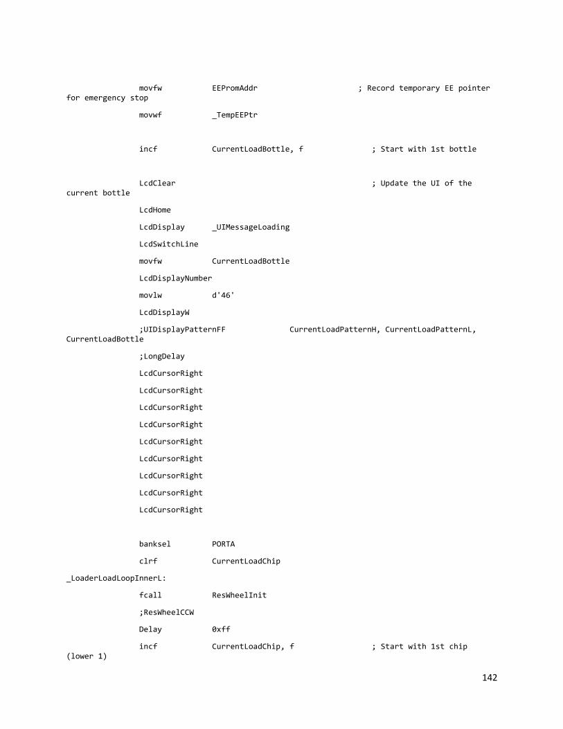
142
movfw EEPromAddr ; Record temporary EE pointer for emergency stop
movwf _TempEEPtr
incf CurrentLoadBottle, f ; Start with 1st bottle
LcdClear ; Update the UI of the current bottle
LcdHome
LcdDisplay _UIMessageLoading
LcdSwitchLine
movfw CurrentLoadBottle
LcdDisplayNumber
movlw d'46'
LcdDisplayW
;UIDisplayPatternFF CurrentLoadPatternH, CurrentLoadPatternL, CurrentLoadBottle
;LongDelay
LcdCursorRight
LcdCursorRight
LcdCursorRight
LcdCursorRight
LcdCursorRight
LcdCursorRight
LcdCursorRight
LcdCursorRight
LcdCursorRight
banksel PORTA
clrf CurrentLoadChip
_LoaderLoadLoopInnerL:
fcall ResWheelInit
;ResWheelCCW
Delay 0xff
incf CurrentLoadChip, f ; Start with 1st chip (lower 1)

143
movfw CurrentLoadChip
addlw -0x1
fcall Mask
movfw _LoaderChipMask
andwf CurrentLoadPatternL, w
btfsc STATUS, Z
goto _LoaderLoadLoopInnerLA
goto _LoaderLoadLoopInnerLC
_LoaderLoadLoopInnerLA:
movlw 'A'
LcdDisplayW
LcdCursorLeft
LcdCursorLeft
fcall FinANextPosition
goto _LoaderLoadLoopInnerLNext
_LoaderLoadLoopInnerLC:
movlw 'C'
LcdDisplayW
LcdCursorLeft
LcdCursorLeft
fcall FinCNextPosition
goto _LoaderLoadLoopInnerLNext
_LoaderLoadLoopInnerLNext:
movfw CurrentLoadChip
addlw -0x5
btfsc STATUS, C
goto _LoaderLoadLoopInnerH
goto _LoaderLoadLoopInnerL
_LoaderLoadLoopInnerH:
;ResWheelCCW
fcall ResWheelInit

144
Delay 0xff
incf CurrentLoadChip, f ; Start with 1
movfw CurrentLoadChip
addlw -0x6
fcall Mask
movfw _LoaderChipMask
andwf CurrentLoadPatternH, w
btfsc STATUS, Z
goto _LoaderLoadLoopInnerHA
goto _LoaderLoadLoopInnerHC
_LoaderLoadLoopInnerHA:
movlw 'A'
LcdDisplayW
LcdCursorLeft
LcdCursorLeft
fcall FinANextPosition
goto _LoaderLoadLoopInnerHNext
_LoaderLoadLoopInnerHC:
movlw 'C'
LcdDisplayW
LcdCursorLeft
LcdCursorLeft
fcall FinCNextPosition
goto _LoaderLoadLoopInnerHNext
_LoaderLoadLoopInnerHNext:
movfw CurrentLoadChip
addlw -0xa
btfsc STATUS, C
goto _LoaderLoadLoopEnd
goto _LoaderLoadLoopInnerH
_LoaderLoadLoopEnd:

145
ResWheelStop
LongDelay
return;</editor-fold>
;<editor-fold defaultstate="collapsed" desc="CountChips: Count the remaining chips">
CountChips:
LcdClear
LcdDisplay _UIMessageCounting
ResWheelCCW
clrf 0x45 ; Countchip wait loop
clrf 0x46 ; temporary counter for empty pass A
clrf 0x47 ; CountA
clrf 0x48 ; CountC
clrf 0x49 ; temporary counter for empty pass C
CountChipsA:
fcall FinAPrevPositionRestore
Delay 0x50
FinAStop ; Rotate fin A to count A first
fcall FinAPrevPosition
clrf 0x45
CountChipsWaitA:
banksel PORTC
btfsc ChipLoadSensorA
goto CountChipsIncA
ShortDelay
incf 0x45, f
movlw d'5'
subwf 0x45, w
btfsc STATUS, C
goto CountChipsC
goto CountChipsWaitA

146
CountChipsIncA:
banksel PORTC
btfss ChipLoadSensorA
goto $-1
Delay 0x70
;movlw 'A'
;LcdDisplayW
clrf 0x46
incf 0x47, f
goto CountChipsC
CountChipsC: ; Rotate Fin C to count C next
fcall FinCPrevPositionRestore
Delay 0xa0
FinCStop
fcall FinCPrevPosition
clrf 0x45
CountChipsWaitC:
banksel PORTC
btfsc ChipLoadSensorC
goto CountChipsIncC
ShortDelay
incf 0x45, f
movlw d'5'
subwf 0x45, w
btfsc STATUS, C
goto CountChipsEnd
goto CountChipsWaitC
CountChipsIncC:
banksel PORTC
btfss ChipLoadSensorC
goto $-1
Delay 0x70

147
;movlw 'C'
;LcdDisplayW
clrf 0x49
incf 0x48, f
goto CountChipsEnd
CountChipsEnd:
incf 0x46, f ; Add empty pass count
incf 0x49, f
;Delay 0xcf
movlw d'5' ; Count at least 5 empty pass for A
subwf 0x46, w
btfss STATUS, C
goto CountChipsA
movlw d'5' ; Count at least 5 empty pass for C
subwf 0x49, w
btfss STATUS, C
goto CountChipsA
movff 0x47, ChipsLeftCountA ; Store the counted value
movff 0x48, ChipsLeftCountC
return;</editor-fold>
;<editor-fold defaultstate="collapsed" desc="ReturnChips: Return the counted chips back to the reservoir">
ReturnChips:
fcall FinANextPosition ; Position Fin A/C
fcall FinCNextPosition
FinACW
Delay 0x20
FinAStop

148
ResWheelCW
LongDelay
Delay 0xff
Delay 0xff
clrf 0x46 ; temporary counter for empty pass A
clrf 0x49 ; temporary counter for empty pass C
ReturnChipsLoop:
btfss ChipLoadSensorA
incf 0x46, f
btfss ChipLoadSensorC
incf 0x49, f
fcall FinANextPosition
fcall FinCNextPosition
movlw d'5' ; need both temporary counter have more than 5
subwf 0x46, w
btfss STATUS, C
goto ReturnChipsLoop
movlw d'5'
subwf 0x49, w
btfss STATUS, C
goto ReturnChipsLoop
ReturnChipsEnd:
ResWheelStop
FinAStop
FinCStop
return;</editor-fold>
;<editor-fold defaultstate="collapsed" desc="ResWheelInit: Unjam the reservoir wheel">
ResWheelInit:
banksel PORTC

149
ResWheelCW
Delay d'200'
banksel PORTC
ResWheelCCW
Delay 0xff
Delay 0x50
return
;</editor-fold>
;;<editor-fold defaultstate="collapsed" desc="FinANextPosition">
;FinANextPosition:
; banksel PORTC
; FinACCW
;FinANextPositionLoop:
; KeypadReadChar
; CheckKey 0xf, 0x008
; btfsc FinWheelSensorA
; goto FinANextPositionLoop
; goto FinANextPositionDetected
;
;FinANextPositionDetected:
; FinACCW
; Delay 0x20
; FinACW
; Delay 0x10
; FinAStop
; return
;;</editor-fold>
;
;;<editor-fold defaultstate="collapsed" desc="FinCNextPosition">
;FinCNextPosition:
; banksel PORTC
; FinCCCW
;FinCNextPositionLoop:
; KeypadReadChar

150
; CheckKey 0xf, 0x008
; btfsc FinWheelSensorC
; goto FinCNextPositionLoop
; goto FinCNextPositionDetected
;FinCNextPositionDetected:
;; btfss FinWheelSensorC
;; goto $-1
;; FinCCW
;; Delay 0x10
;; FinCCCW
;; btfss FinWheelSensorC
;; goto $-1
;; FinCCW
;; Delay 0x4
;; FinCStop
; FinCCCW
; Delay 0x25
; FinCCW
; Delay 0x10
; FinCStop
; return;</editor-fold>
;
;;<editor-fold defaultstate="collapsed" desc="FinAPrevPosition">
;FinAPrevPosition:
; FinACW
;FinAPrevPositionLoop:
; KeypadReadChar
; CheckKey 0xf, 0x008
; btfsc FinWheelSensorA
; goto FinAPrevPositionLoop
; goto FinAPrevPositionDetected
;FinAPrevPositionDetected:
; FinACCW
; Delay 0x15
; FinAStop

151
; return
;
;FinAPrevPositionRestore:
; banksel PORTC
; FinACW
; return;</editor-fold>
;
;;<editor-fold defaultstate="collapsed" desc="FinCPrevPosition">
;FinCPrevPosition:
; banksel PORTC
; FinCCW
;FinCPrevPositionLoop:
; KeypadReadChar
; CheckKey 0xf, 0x008
; btfsc FinWheelSensorC
; goto FinCPrevPositionLoop
; goto FinCPrevPositionDetected
;FinCPrevPositionDetected:
; FinCCCW
; Delay 0x10
; FinCStop
; return
;
;FinCPrevPositionRestore:
; banksel PORTC
; FinCCW
; return;</editor-fold>
;<editor-fold defaultstate="collapsed" desc="FinANextPosition">
FinANextPosition:
banksel PORTC
FinACCW
FinANextPositionLoop:
KeypadReadChar
CheckKey 0xf, 0x008

152
btfsc FinWheelSensorA
goto FinANextPositionLoop
goto FinANextPositionDetected
FinANextPositionDetected:
FinACCW
Delay 0x20
FinACW
Delay 0x10
FinAStop
return
;</editor-fold>
;<editor-fold defaultstate="collapsed" desc="FinCNextPosition">
FinCNextPosition:
banksel PORTC
FinCCCW
; clrf 0x45
FinCNextPositionLoop:
; ShortDelay
; incf 0x45, f
KeypadReadChar
CheckKey 0xf, 0x008
; movlw 0x40
; subwf 0x45, w
; btfsc STATUS, C
; goto FinCNextPositionUJ
;
btfsc FinWheelSensorC
goto FinCNextPositionLoop
goto FinCNextPositionDetected
;
;FinCNextPositionUJ:
; FinCCW

153
; Delay 0x5
; clrf 0x45
; goto FinCNextPositionLoop
FinCNextPositionDetected:
btfss FinWheelSensorC
goto $-1
FinCCW
Delay 0x4
FinCCCW
; btfss FinWheelSensorC
; goto $-1
; FinCCW
; Delay 0x4
FinCStop
return;</editor-fold>
;<editor-fold defaultstate="collapsed" desc="FinAPrevPosition">
FinAPrevPosition:
FinACW
FinAPrevPositionLoop:
KeypadReadChar
CheckKey 0xf, 0x008
btfsc FinWheelSensorA
goto FinAPrevPositionLoop
goto FinAPrevPositionDetected
FinAPrevPositionDetected:
FinACCW
Delay 0x15
FinAStop
return
FinAPrevPositionRestore:
banksel PORTC
FinACW

154
return;</editor-fold>
;<editor-fold defaultstate="collapsed" desc="FinCPrevPosition">
FinCPrevPosition:
banksel PORTC
FinCCW
FinCPrevPositionLoop:
KeypadReadChar
CheckKey 0xf, 0x008
btfsc FinWheelSensorC
goto FinCPrevPositionLoop
goto FinCPrevPositionDetected
FinCPrevPositionDetected:
FinCCCW
Delay 0x15
FinCStop
return
FinCPrevPositionRestore:
banksel PORTC
FinCCW
return;</editor-fold>
;<editor-fold defaultstate="collapsed" desc="LidCoverPosition: Re-position the lid cover apparatus">
LidCoverPosition:
banksel PORTB
LidCoverCW
LidCoverPositionSensor1:
TinyDelay
KeypadReadChar
CheckKey 0xf, 0x008
btfss LidCoverSensor1
goto LidCoverPositionSensor1
LidCoverCCW

155
Delay 0x15
LidCoverStop
return
;</editor-fold>
;<editor-fold defaultstate="collapsed" desc="LidCoverHalf: Go half way of the lid cover">
LidCoverHalf:
banksel PORTB
LidCoverCCW
Delay 0xff
Delay 0xcf
LidCoverStop
Delay 0xcf
LidCoverCW
Delay d'140'
LidCoverStop
return
;</editor-fold>
End

156
LOADER.INC ifndef fcall
#include <fcall.inc>
endif
ifndef _LoaderLoad
extern _LoaderLoad
endif
#define _TempEEPtr 0x3b
LoaderLoad: macro
fcall _LoaderLoad
endm

157
MAIN.ASM ;**********************************************************************
; Entry point
;**********************************************************************
;<editor-fold defaultstate="collapsed" desc="Imports and Configs">
list p=16f877
ifndef PORTA
#include <p16f877.inc>
endif
ifndef fcall
#include <fcall.inc>
endif
ifndef StackInit
#include <stack.inc> ; Stack library
endif
ifndef KeypadInit
#include <keypad.inc> ; Keypad library
endif
ifndef LcdInit
#include <lcd.inc> ; Lcd library
endif
ifndef UIInit
#include <ui.inc> ; UI library
endif
ifndef UIInitBottleNumber
#include <ui2.inc> ; UI library
endif
ifndef Divide
#include <math.inc> ; Math library
endif
ifndef TimerCheck
#include <timer.inc> ; Timer library

158
endif
ifndef LoaderLoad
#include <loader.inc> ; Loader
endif
ifndef BaseMotorDir
#include <motor.inc> ; Motor
endif
ifndef EEPromAddr
#include <eeprom.inc> ; EEProm library
endif
#include <rtc.inc>
__config _CP_OFF & _WDT_OFF & _BODEN_OFF & _PWRTE_ON & _HS_OSC & _WRT_ENABLE_ON & _LVP_OFF & _DEBUG_OFF & _CPD_OFF
global Finish
global Start2
#define TRISAIO b'00111111'
#define TRISBIO b'11110011'
#define TRISCIO b'00011000'
#define TRISDIO b'00000000'
#define TRISEIO b'00000010' ; Watch out the configuration bits
cblock 0x79
WTemp ; 9
StatusTemp ; a
PCLATHTemp ; b
endc
;</editor-fold>
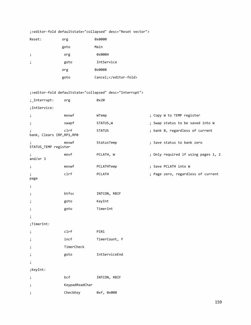
159
;<editor-fold defaultstate="collapsed" desc="Reset vector">
Reset: org 0x0000
goto Main
; org 0x0004
; goto IntService
org 0x0008
goto Cancel;</editor-fold>
;<editor-fold defaultstate="collapsed" desc="Interrupt">
;_Interrupt: org 0x20
;IntService:
; movwf WTemp ; Copy W to TEMP register
; swapf STATUS,W ; Swap status to be saved into W
; clrf STATUS ; bank 0, regardless of current bank, Clears IRP,RP1,RP0
; movwf StatusTemp ; Save status to bank zero STATUS_TEMP register
; movf PCLATH, W ; Only required if using pages 1, 2 and/or 3
; movwf PCLATHTemp ; Save PCLATH into W
; clrf PCLATH ; Page zero, regardless of current page
;
; btfsc INTCON, RBIF
; goto KeyInt
; goto TimerInt
;
;TimerInt:
; clrf PIR1
; incf TimerCount, f
; TimerCheck
; goto IntServiceEnd
;
;KeyInt:
; bcf INTCON, RBIF
; KeypadReadChar
; CheckKey 0xf, 0x008

160
; goto IntServiceEnd
;
;IntServiceEnd:
; movf PCLATHTemp, W ; Restore PCLATH
; movwf PCLATH ; Move W into PCLATH
; swapf StatusTemp,W ; Swap STATUS_TEMP register into W
; ; (sets bank to original state)
; movwf STATUS ; Move W into STATUS register
; swapf WTemp,F ; Swap W_TEMP
; swapf WTemp,W ; Swap W_TEMP into W
; retfie
;</editor-fold>
;<editor-fold defaultstate="collapsed" desc="Main">
Main: ;org 0x100
fcall Init
lgoto Start;</editor-fold>
;<editor-fold defaultstate="collapsed" desc="Init">
Init:
banksel TRISA ; Initialize the I/O pins
movlw TRISAIO
movwf TRISA
movlw 0x06
movwf ADCON1 ; All port A, E is digital
movlw TRISBIO
movwf TRISB
movlw TRISCIO
movwf TRISC
movlw TRISDIO
movwf TRISD
movlw TRISEIO
movwf TRISE
banksel PORTA

161
clrf PORTB
clrf PORTC
clrf PORTE
clrf INTCON
StackInit ; Initialize the stack
UIInit ; Initialize the LCD and the keypad
;TimerInit ; Initialize the timer module
;<editor-fold defaultstate="collapsed" desc="comment">
fcall i2c_common_setup
;rtc_resetAll
;fcall set_rtc_time;</editor-fold>
LcdClear
return
;</editor-fold>
;<editor-fold defaultstate="collapsed" desc="Start">
Start:
; Delay 0xff
; banksel PORTB
; btfss PORTB, 1
; goto Start
; ResWheelCCW
; goto $
;
;;<editor-fold defaultstate="collapsed" desc="Output pin test code">
;Output:
; LcdClear
; banksel PORTC
; bsf PORTC, 5
;Loop2:
; banksel PORTC
; FinACW

162
; FinCCW
; ResWheelCW
; BaseCW
; LongDelay
; FinACCW
; FinCCCW
; ResWheelCCW
; BaseCCW
; LongDelay
; FinAStop
; FinCStop
; ResWheelStop
; BaseStop
; LongDelay
;LidTest:
; call LidCoverPosition
; LongDelay
; btfsc PORTB, 1
; goto Input
; goto Loop2
;;</editor-fold>
;
;;<editor-fold defaultstate="collapsed" desc="Input pin test code">
;Input:
; clrf PORTB
; LcdHome
;
; banksel PORTA
; movlw 'A'
; LcdDisplayW
; movlw ':'
; LcdDisplayW
; movfw PORTA
; LcdDisplayNumber
; movlw ' '

163
; LcdDisplayW
;
; movlw 'B'
; LcdDisplayW
; movlw ':'
; LcdDisplayW
; movfw PORTB
; LcdDisplayNumber
; movlw ' '
; LcdDisplayW
;
; movlw 'C'
; LcdDisplayW
; movlw ':'
; LcdDisplayW
; movfw PORTC
; LcdDisplayNumber
; movlw ' '
; LcdDisplayW
;
; LcdSwitchLine
;
; movlw 'D'
; LcdDisplayW
; movlw ':'
; LcdDisplayW
; movfw PORTD
; LcdDisplayNumber
; movlw ' '
; LcdDisplayW
;
; movlw 'E'
; LcdDisplayW
; movlw ':'
; LcdDisplayW

164
; movfw PORTE
; LcdDisplayNumber
; movlw ' '
; LcdDisplayW
;
; Delay 0xff
;
; btfsc PORTB, 1
; goto Clock
; goto Input
;;</editor-fold>
;</editor-fold>
;<editor-fold defaultstate="collapsed" desc="Clock-Start">
Clock:
LcdClear
LcdCursorOff
Delay 0xff
LcdDisplay _UIMessageMachineName
LongDelay
LcdClear
ClockLoop:
;LcdDisplayDateTime
;Delay d'250'
;Delay d'207'
UIWelcome
Delay d'10'
btfss PORTB, 1
goto ClockLoop
UIInitBottleNumber
UIInitPattern
Start2:
UIConfirmStart Run, Cancel;</editor-fold>

165
;<editor-fold defaultstate="collapsed" desc="Cancel">
Cancel:
EEPromReadA 0x0
movfw _TempEEPtr
subwf EEPromValue, w
btfsc STATUS, Z
goto CancelNext
ResetPtr:
movfw _TempEEPtr
addlw 0x1
movwf EEPromValue
clrf EEPromAddr
EEPromWrite
TimerOff
CancelNext:
UICancel
LcdClear
banksel PORTB
clrf PORTB
clrf PORTC
clrf PORTE
lgoto ClockLoop
;</editor-fold>
;<editor-fold defaultstate="collapsed" desc="Run">
Run:
LoaderLoad
;</editor-fold>
;<editor-fold defaultstate="collapsed" desc="Finish">
Finish:
UIDisplayAllPattern
UIFinished

166
KeypadWaitChar
LcdClear
goto ClockLoop
;</editor-fold>
;;<editor-fold defaultstate="collapsed" desc="RTC reset">
;set_rtc_time:
; rtc_resetAll ;reset rtc
;
; rtc_set 0x00, B'10000000'
;
; ;set time
; rtc_set 0x06, 0x13 ; Year
; rtc_set 0x05, 0x4 ; Month
; rtc_set 0x04, 0x9 ; Date
; rtc_set 0x03, 0x2 ; Day
; rtc_set 0x02, 0x4 ; Hours
; rtc_set 0x01, 0x56 ; Minutes
; rtc_set 0x00, 0x0 ; Seconds
; return
;</editor-fold>
End

167
MATH.ASM ;**********************************************************************
; Math Library for PIC16
;**********************************************************************
;<editor-fold defaultstate="collapsed" desc="Imports, exports, and constants">
global _Divide
global _Multiply
#define Quotient 0x0
#define Remainder 0x1
#define Divisor 0x0
#define Divident 0x1
#define MultiplierA 0x0
#define MultiplierB 0x1
#define MultiplyResult 0x0
ifndef PORTA
#include <p16f877.inc>
endif
ifndef Stack
#include <stack.inc>
endif
ifndef LcdInit
#include <lcd.inc>
endif
cblock 0x28
_Divisor ;28
_Divident ;29
_Quotient ;2a
_MultiplierA ;2b
_MultiplierB ;2c
_MultiplyResult ;2d
endc;</editor-fold>

168
code
; Divide 8 bit number by 8 bit
; Stack: Quotient/Remainder-----Divisor<---/Divident
;<editor-fold defaultstate="collapsed" desc="_Divide: divide 8-bit number by 8-bit">
_Divide:
StackReadF Divisor, _Divisor ; Read divisor
StackReadF Divident, _Divident ; Read divident
clrf _Quotient
_DivideLoop:
incf _Quotient, f
movfw _Divisor
subwf _Divident, f
btfss STATUS, C ; Check borrow bit
goto _DivideLoopEnd
goto _DivideLoop
_DivideLoopEnd:
movfw _Divisor ; Add back one divisor to divient to get remainder
addwf _Divident, f
StackWriteF Divident, _Divident ; The divident stack spot is now remainder
decf _Quotient, f
StackWriteF Divisor, _Quotient ; The divisor stack spot is now quotient
return;</editor-fold>
; Multiply 8 bit number by 8 bit
; Stack: Result/MultiplyerA ------------- MultiplyerA/MultiplyerB
;<editor-fold defaultstate="collapsed" desc="_Multiply: Multiply 8 bit number by 8 bit">
_Multiply:
StackReadF MultiplierA, _MultiplierA
StackReadF MultiplierB, _MultiplierB

169
clrf _MultiplyResult
_MultiplyLoop:
movfw _MultiplierB ; Check if reaches end of the loop
xorlw b'00000000'
btfsc STATUS, Z
goto _MultiplyLoopEnd
decf _MultiplierB, f ; Decrement B
movfw _MultiplierA ; Add A to the result
addwf _MultiplyResult, f
goto _MultiplyLoop
_MultiplyLoopEnd:
StackWriteF MultiplyResult, _MultiplyResult
return;</editor-fold>
end

170
MATH.INC ;**********************************************************************
; Math Library for PIC16
;**********************************************************************
;<editor-fold defaultstate="collapsed" desc="Imports and constants">
#define Quotient 0x0
#define Remainder 0x1
#define Divisor 0x0
#define Divident 0x1
ifndef _Divide
extern _Divide
extern _Multiply
endif;</editor-fold>
;<editor-fold defaultstate="collapsed" desc="Divide: divide a 8-bit number by 8-bit">
Divide: macro
fcall _Divide
endm;</editor-fold>
;<editor-fold defaultstate="collapsed" desc="Multiply: multiply a 8-bit number by 8-bit">
Multiply: macro
fcall _Multiply
endm;</editor-fold>
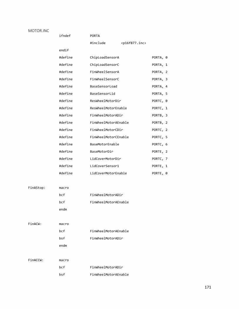
171
MOTOR.INC ifndef PORTA
#include <p16f877.inc>
endif
#define ChipLoadSensorA PORTA, 0
#define ChipLoadSensorC PORTA, 1
#define FinWheelSensorA PORTA, 2
#define FinWheelSensorC PORTA, 3
#define BaseSensorLoad PORTA, 4
#define BaseSensorLid PORTA, 5
#define ResWheelMotorDir PORTC, 0
#define ResWheelMotorEnable PORTC, 1
#define FinWheelMotorADir PORTB, 3
#define FinWheelMotorAEnable PORTB, 2
#define FinWheelMotorCDir PORTC, 2
#define FinWheelMotorCEnable PORTC, 5
#define BaseMotorEnable PORTC, 6
#define BaseMotorDir PORTE, 2
#define LidCoverMotorDir PORTC, 7
#define LidCoverSensor1 PORTE, 1
#define LidCoverMotorEnable PORTE, 0
FinAStop: macro
bcf FinWheelMotorADir
bcf FinWheelMotorAEnable
endm
FinACW: macro
bcf FinWheelMotorAEnable
bsf FinWheelMotorADir
endm
FinACCW: macro
bcf FinWheelMotorADir
bsf FinWheelMotorAEnable

172
endm
FinCStop: macro
bcf FinWheelMotorCDir
bcf FinWheelMotorCEnable
endm
FinCCW: macro
bcf FinWheelMotorCEnable
bsf FinWheelMotorCDir
endm
FinCCCW: macro
bcf FinWheelMotorCDir
bsf FinWheelMotorCEnable
endm
ResWheelStop: macro
bcf ResWheelMotorDir
bcf ResWheelMotorEnable
endm
ResWheelCW: macro
bcf ResWheelMotorEnable
bsf ResWheelMotorDir
endm
ResWheelCCW: macro
bcf ResWheelMotorDir
bsf ResWheelMotorEnable
endm
BaseStop: macro
bcf BaseMotorDir
bcf BaseMotorEnable

173
endm
BaseCW: macro
bcf BaseMotorEnable
bsf BaseMotorDir
endm
BaseCCW: macro
bcf BaseMotorDir
bsf BaseMotorEnable
endm
LidCoverStop: macro
bcf LidCoverMotorDir
bcf LidCoverMotorEnable
endm
LidCoverCW: macro
bcf LidCoverMotorEnable
bsf LidCoverMotorDir
endm
LidCoverCCW: macro
bcf LidCoverMotorDir
bsf LidCoverMotorEnable
endm

174
RTC.INC ;External labels
extern write_rtc,read_rtc,rtc_convert,i2c_common_setup
;RTC Macros;;;;;;;;;;;;;;;;;;;;;;;;;;;;;;;;;;;;;;;;
rtc_resetAll macro
;input: none
;output: none
;desc: Resets all the time keeping registers on the RTC to zero
banksel 0x74
clrf 0x74
banksel 0x73
clrf 0x73
fcall write_rtc ;Write 0 to Seconds
banksel 0x73
incf 0x73 ;Set register address to 1
fcall write_rtc
banksel 0x73
incf 0x73 ;Set register address to 2
fcall write_rtc
banksel 0x73
incf 0x73 ;Set register address to 3
fcall write_rtc
banksel 0x73
incf 0x73 ;Set register address to 4
fcall write_rtc
banksel 0x73
incf 0x73 ;Set register address to 5
fcall write_rtc
banksel 0x73
incf 0x73 ;Set register address to 6
fcall write_rtc
endm

175
rtc_set macro addliteral,datliteral
;input: addliteral: value of address
; datliteral: value of data
;output: none
;desc: loads the data in datliteral into the
; address specified by addliteral in the RTC
banksel 0x73
movlw addliteral
movwf 0x73
banksel 0x74
movlw datliteral
movwf 0x74
fcall write_rtc
endm
rtc_read macro addliteral
;input: addliteral
;output: 0x75, 0x77, 0x78
;desc: From the selected register in the RTC, read the data
; and load it into 0x75. 0x75 is also converted into
; ASCII characters and the tens digit is placed into
; 0x77 and the ones digit is placed in 0x78
movlw addliteral
banksel 0x73
movwf 0x73
fcall read_rtc
banksel 0x75
movf 0x75,w
fcall rtc_convert
endm

176
STACK.INC ;**********************************************************************
; Stack Library for PIC16
;**********************************************************************
;<editor-fold defaultstate="collapsed" desc="Imports and constants">
ifndef PORTA
#include <p16f877.inc>
endif
#define Stack INDF
#define StackPtr FSR
#define TempW 0x40
#define TempStack 0x41;</editor-fold>
;<editor-fold defaultstate="collapsed" desc="Initialize the stack to 0x7e">
StackInit: macro
movlw 0x71
movwf StackPtr
endm;</editor-fold>
;<editor-fold defaultstate="collapsed" desc="StackJmp: Jump stack upwards with specified size">
StackJmp: macro Size
movwf TempW
movlw Size
subwf StackPtr, f
movfw TempW
endm;</editor-fold>
;<editor-fold defaultstate="collapsed" desc="StackInc: Increment stack by 1">
StackInc: macro
decf StackPtr, f
endm;</editor-fold>
;<editor-fold defaultstate="collapsed" desc="StackDec: Decrement stack by specified size">
StackDec: macro Size
movwf TempW

177
movlw Size
addwf StackPtr, f
movfw TempW
endm;</editor-fold>
;<editor-fold defaultstate="collapsed" desc="StackPush: Push the stack with a label and value">
StackPush: macro Label, Literal
banksel PORTA
movwf TempW
StackInc
variable Label=Stack
movlw Literal
movwf Stack
movfw TempW
endm;</editor-fold>
;<editor-fold defaultstate="collapsed" desc="StackPushL: Push the stack with a literal value">
StackPushL: macro Value
banksel PORTA
movwf TempW
StackInc
movlw Value
movwf Stack
movfw TempW
endm;</editor-fold>
;<editor-fold defaultstate="collapsed" desc="StackPushW: Push the stack with a label with value as the working register">
StackPushW: macro Label
banksel PORTA
movwf TempW
StackInc
variable Label=Stack
movwf Stack
;movfw INDF

178
movfw TempW
endm;</editor-fold>
;<editor-fold defaultstate="collapsed" desc="StackWriteW: Write the content in WREG to the stack with a relative address to the stack pointer">
StackWriteW: macro RelativeAddr
banksel PORTA
StackDec RelativeAddr
movwf Stack
StackJmp RelativeAddr
endm;</editor-fold>
;<editor-fold defaultstate="collapsed" desc="StackWriteL: Write the literal value to the stack with a relative address to the stack pointer">
StackWriteL: macro RelativeAddr, Value
banksel PORTA
movwf TempW
StackDec RelativeAddr
movlw Value
movwf Stack
StackJmp RelativeAddr
movfw TempW
endm;</editor-fold>
;<editor-fold defaultstate="collapsed" desc="StackWriteF: Write the file to the stack with a relative address">
StackWriteF: macro RelativeAddr, File
banksel PORTA
movwf TempW
StackDec RelativeAddr
banksel File
movfw File
banksel PORTA
movwf Stack
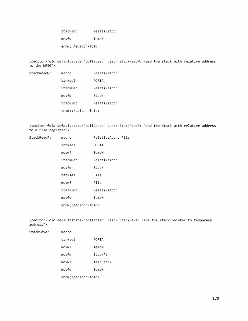
179
StackJmp RelativeAddr
movfw TempW
endm;</editor-fold>
;<editor-fold defaultstate="collapsed" desc="StackReadW: Read the stack with relative address to the WREG">
StackReadW: macro RelativeAddr
banksel PORTA
StackDec RelativeAddr
movfw Stack
StackJmp RelativeAddr
endm;</editor-fold>
;<editor-fold defaultstate="collapsed" desc="StackReadF: Read the stack with relative address to a file register">
StackReadF: macro RelativeAddr, File
banksel PORTA
movwf TempW
StackDec RelativeAddr
movfw Stack
banksel File
movwf File
StackJmp RelativeAddr
movfw TempW
endm;</editor-fold>
;<editor-fold defaultstate="collapsed" desc="StackSave: Save the stack pointer to temporary address">
StackSave: macro
banksel PORTA
movwf TempW
movfw StackPtr
movwf TempStack
movfw TempW
endm;</editor-fold>

180
;<editor-fold defaultstate="collapsed" desc="StackRestore: Restore the temporary stack pointer">
StackRestore: macro
banksel PORTA
movwf TempW
movfw TempStack
movwf StackPtr
movfw TempW
endm;</editor-fold>
;<editor-fold defaultstate="collapsed" desc="var: Dynamically decalare a variable">
var: macro Label
banksel PORTA
movfw TempW
StackInc
variable Label=INDF
movwf TempW
endm;</editor-fold>

181
TABLE.ASM ;**********************************************************************
; Lookup Table Library
;**********************************************************************
;<editor-fold defaultstate="collapsed" desc="Imports and exports">
ifndef PORTA
#include <p16f877.inc>
endif
ifndef Stack
#include <stack.inc>
endif
ifndef movff
#include <fcall.inc>
endif
global _TableCall
global _TableLookupHL
#define StatusTemp 0x2e
;</editor-fold>
_TableLookup: code
;<editor-fold defaultstate="collapsed" desc="_TableCall: Call table by changing PCL with W">
_TableCall:
movwf PCL
;</editor-fold>
;<editor-fold defaultstate="collapsed" desc="_TableLookupHL: Lookup table from offset/low/high in the stack">
_TableLookupHL:
;movff STATUS, StatusTemp
StackDec 0x02
movfw Stack
movwf PCLATH

182
StackInc
movfw Stack
StackInc
addwf Stack, w
btfsc STATUS, C
incf PCLATH, f
;movff StatusTemp, STATUS
movwf PCL
;call _TableCall
;pagesel $
;movff StatusTemp, STATUS
;return
;</editor-fold>
End

183
TABLE.INC ;**********************************************************************
; Lookup Table Library
;**********************************************************************
;<editor-fold defaultstate="collapsed" desc="Imports and exports">
ifndef PORTA
#include <p16f877.inc>
endif
ifndef Stack
#include <stack.inc>
endif
ifndef _TableCall
extern _TableCall
extern _TableLookupHL
endif;</editor-fold>
;<editor-fold defaultstate="collapsed" desc="TableLookup: Lookup a table address with offset">
TableLookup: macro Table, Offset
movlw HIGH Table ; load PCLATH with base of table
movwf PCLATH
movlw LOW Table ; add offset to base
banksel Offset
addwf Offset, w
btfsc STATUS, C ; if overflow
incf PCLATH, f ; increment PCLATH
call _TableCall
banksel PORTA
pagesel $
endm;</editor-fold>
;<editor-fold defaultstate="collapsed" desc="Lookup table with address specified in offset/low/high order in the stack">
TableLookupHL: macro
fcall _TableLookupHL
endm;</editor-fold>

184
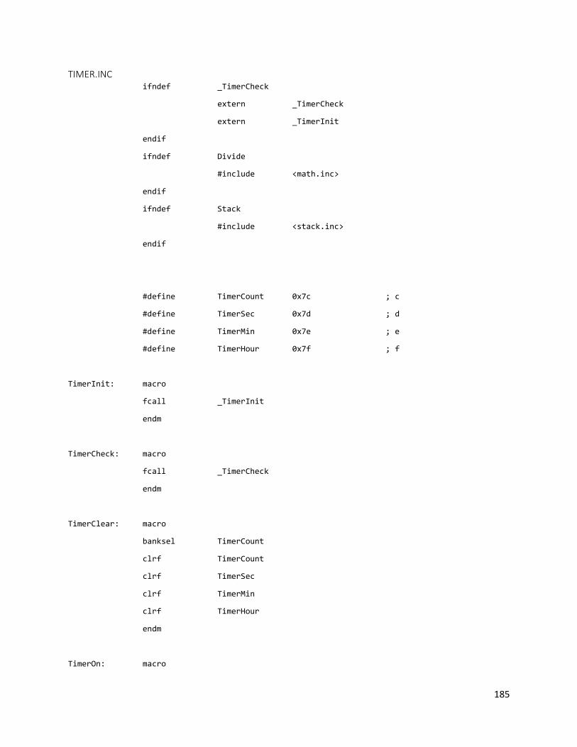
185
TIMER.INC ifndef _TimerCheck
extern _TimerCheck
extern _TimerInit
endif
ifndef Divide
#include <math.inc>
endif
ifndef Stack
#include <stack.inc>
endif
#define TimerCount 0x7c ; c
#define TimerSec 0x7d ; d
#define TimerMin 0x7e ; e
#define TimerHour 0x7f ; f
TimerInit: macro
fcall _TimerInit
endm
TimerCheck: macro
fcall _TimerCheck
endm
TimerClear: macro
banksel TimerCount
clrf TimerCount
clrf TimerSec
clrf TimerMin
clrf TimerHour
endm
TimerOn: macro

186
rtc_read 0x0
StackInc
StackWriteF 0x0, 0x77
StackPushL 0xa
Multiply
StackReadF 0x0, TimerSec
StackDec 0x2
movfw 0x78
addwf TimerSec, f
rtc_read 0x1
StackInc
StackWriteF 0x0, 0x77
StackPushL 0xa
Multiply
StackReadF 0x0, TimerMin
StackDec 0x2
movfw 0x78
addwf TimerMin, f
endm
TimerOff: macro
local TimerSecCarry, TimerOff2, TimerMinCarry, TimerOffEnd
rtc_read 0x0 ; Read current seconds into timer count
StackInc
StackWriteF 0x0, 0x77
StackPushL 0xa
Multiply
StackReadF 0x0, TimerCount
StackDec 0x2
movfw 0x78
addwf TimerCount, f
movfw TimerSec ; Read current seconds into timer count

187
subwf TimerCount, f
movfw TimerCount
movwf TimerSec
movfw TimerSec ; Substract from the starting seconds
addlw -d'60'
btfsc STATUS, C
goto TimerSecCarry
goto TimerOff2
TimerSecCarry:
incf TimerMin, f ; Carry of seconds substraction
movlw d'60'
addwf TimerSec, f
TimerOff2:
clrf TimerCount ; Read current minutes into timer count
rtc_read 0x1
StackInc
StackWriteF 0x0, 0x77
StackPushL 0xa
Multiply
StackReadF 0x0, TimerCount
StackDec 0x2
movfw 0x78
addwf TimerCount, f
movfw TimerMin ; Substract from the starting minutes
subwf TimerCount, f
movfw TimerCount
movwf TimerMin
movfw TimerMin

188
addlw -d'60'
btfsc STATUS, C
goto TimerMinCarry
goto TimerOffEnd
TimerMinCarry:
movlw d'60' ; Carry of minutes substraction
addwf TimerMin, f
TimerOffEnd:
Endm

189
UI.ASM ;**********************************************************************
; UI Interaction
;**********************************************************************
;<editor-fold defaultstate="collapsed" desc="Imports, exports, and variables">
ifndef PORTA
#include <p16f877.inc>
endif
ifndef fcall
#include <fcall.inc> ; delay
endif
ifndef Delay
#include <delay.inc> ; delay
endif
ifndef LcdInit
#include <lcd.inc> ; lcd library
endif
ifndef StackInit
#include <stack.inc> ; stack library
endif
ifndef KeypadInit
#include <keypad.inc> ; keypad library
endif
ifndef Divide
#include <math.inc>
endif
ifndef TimerInit
#include <timer.inc>
endif
global _UIInit
global _UIWelcome
global _UIFinished
global _UIChipsLeft

190
global _UIReadInput
global _UIParseInputNumber
global _UIWaitPond
global _UICancel
global _UIDisplayPattern
global _UIMessageMachineName
global _UIMessageWaitPond
global _UIMessageCancel
global _UIMessageCancelled
global _UIMessageCounting
cblock 0x58
_UIInputLength
_UIInputStackPtr
_UIInputStack:0xa ; Maximum of 10 characters can be input
_UIInputNumber
_UIInputStackPtrEnd
_UIInputMax
_UIInputCurrentChar
endc
cblock 0x42
TempW2
TempMask
TempCounter
endc
#define PondKey 0xe
#define StarKey 0xc
#define CancelKey 0xf
;</editor-fold>
_UI: code

191
;<editor-fold defaultstate="collapsed" desc="UI built in messages">
_UIMessageMachineName:
dt " Chip Washer", 0
_UIMessageWelcome:
dt "Welcome", 0
_UIMessageWaitPond:
dt "Ready to start", 0
_UIMessageCancel:
dt "OK/Cancel", 0
_UIMessageCancelled:
dt "Task cancelled", 0
_UIMessageFinished:
dt "Finished in ", 0
_UIMessageChipsLeft:
dt "Chips left ", 0
_UIMessageCounting:
dt "Counting...", 0
;</editor-fold>
;<editor-fold defaultstate="collapsed" desc="_UIInit: Initialize LCD and keypad">
_UIInit:
LcdInit
KeypadInit
return;</editor-fold>
;<editor-fold defaultstate="collapsed" desc="_UIWelcome: Display the welcome message">
_UIWelcome:
LcdHome
LcdDisplay _UIMessageWelcome
LcdSwitchLine
LcdDisplayDateTime
;KeypadWaitChar
return;</editor-fold>
;;<editor-fold defaultstate="collapsed" desc="_UILoading: Display loading message">
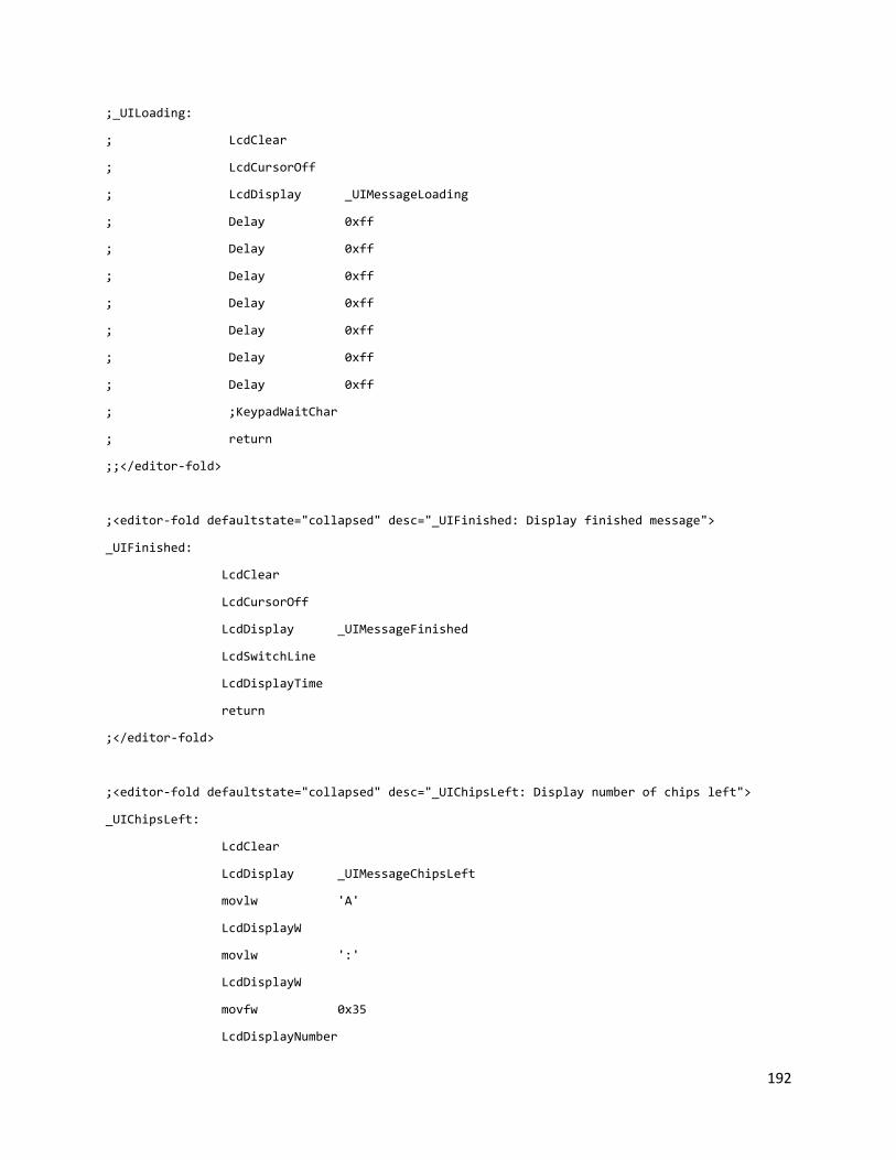
192
;_UILoading:
; LcdClear
; LcdCursorOff
; LcdDisplay _UIMessageLoading
; Delay 0xff
; Delay 0xff
; Delay 0xff
; Delay 0xff
; Delay 0xff
; Delay 0xff
; Delay 0xff
; ;KeypadWaitChar
; return
;;</editor-fold>
;<editor-fold defaultstate="collapsed" desc="_UIFinished: Display finished message">
_UIFinished:
LcdClear
LcdCursorOff
LcdDisplay _UIMessageFinished
LcdSwitchLine
LcdDisplayTime
return
;</editor-fold>
;<editor-fold defaultstate="collapsed" desc="_UIChipsLeft: Display number of chips left">
_UIChipsLeft:
LcdClear
LcdDisplay _UIMessageChipsLeft
movlw 'A'
LcdDisplayW
movlw ':'
LcdDisplayW
movfw 0x35
LcdDisplayNumber

193
LcdSwitchLine
LcdDisplay _UIMessageChipsLeft
movlw 'C'
LcdDisplayW
movlw ':'
LcdDisplayW
movfw 0x36
LcdDisplayNumber
;fcall _UIWaitPond
return;</editor-fold>
;<editor-fold defaultstate="collapsed" desc="_UIWaitPond">
_UIWaitPond:
KeypadWaitChar
CheckKey PondKey, _UIWaitPondEnd
CheckKey CancelKey, 0x0008
goto _UIWaitPond
_UIWaitPondEnd:
return
;</editor-fold>
;<editor-fold defaultstate="collapsed" desc="Mask: Generate mask bits">
Mask:
movwf TempCounter
clrf TempMask
bsf TempMask, 0
_MaskLoop:
movfw TempCounter
xorlw b'00000000'
btfsc STATUS, Z
goto _MaskLoopEnd
decf TempCounter, f

194
bcf STATUS, C
rlf TempMask, f
goto _MaskLoop
_MaskLoopEnd:
return;</editor-fold>
;<editor-fold defaultstate="collapsed" desc="_UIReadInputValidate: Validate input using mask">
_UIReadInputValidate: macro Addr
fcall Mask
StackRestore
StackReadW Addr
andwf TempMask, w
btfsc STATUS, Z
goto _UIReadInputLoop
goto _UIReadInputDisplay
endm;</editor-fold>
;<editor-fold defaultstate="collapsed" desc="_UIReadInput: Aggregate the result with certain length and character validator">
_UIReadInput:
; Test the input without any validator and output the exact same message
; Just use the stack to store the characters
; Need a parameter to specify the length of the expected input
; Length is saved in 0x02 of the stack
; HIGH Validator is saved in the 0x01 0f the stack
; LOW Validator is saved in 0x00 of the stack
clrf _UIInputMax
StackReadF 0x2, _UIInputLength
StackSave ; Save the stack and switch to UIInput Stack
movlw _UIInputStackPtr
addlw 0xa ; Set the stack pointer to the bottom of the input stack
movwf _UIInputStackPtr

195
movfw _UIInputStackPtr
movwf StackPtr
_UIReadInputLoop:
KeypadWaitChar
movwf TempW2
movfw TempW2
CheckKey PondKey, _UIReadInputLoopNext ; Check if it is # key then go to next
CheckKey StarKey, _UIReadInputDelete ; Check if it is * key then decrement stack
CheckKey CancelKey, 0x0008 ; Check if D then cancel
addlw -0x8 ; Get lower bits
btfsc STATUS, C
goto _UIReadInputValidateH
addlw 0x8
goto _UIReadInputValidateL
_UIReadInputValidateH:
_UIReadInputValidate 0x1
_UIReadInputValidateL:
_UIReadInputValidate 0x0
_UIReadInputDisplay:
StackSave
movff _UIInputStackPtr, StackPtr
StackWriteF 0x0, TempW2
KeypadDecode Stack
LcdDisplayW

196
movfw StackPtr ; Check if the maximum reading length is reached
sublw _UIInputStackPtr
btfsc STATUS, Z
goto _UIReadInputMax ; If reached
clrf _UIInputMax ; Clear max flag
movfw _UIInputLength ; Check if reached the expeceted input length
addwf _UIInputStackPtr, w
movfw _UIInputLength
addwf _UIInputStackPtr, w
addlw -0x0b
sublw _UIInputStackPtr
btfsc STATUS, Z
goto _UIReadInputMax
decf StackPtr, f
decf _UIInputStackPtr, f
goto _UIReadInputLoop
_UIReadInputMax:
LcdCursorLeft
movlw 0x1
movwf _UIInputMax
goto _UIReadInputLoop
_UIReadInputDelete:
movlw 0x20 ; Check if it is at the minimum
LcdDisplayW
LcdCursorLeft
movfw _UIInputStackPtr
addlw -0x0a
sublw _UIInputStackPtr

197
btfss STATUS, Z
goto _UIReadInputDelete2
goto _UIReadInputLoop
_UIReadInputDelete2:
incf StackPtr, f
incf _UIInputStackPtr, f
LcdCursorLeft
lgoto _UIReadInputLoop
_UIReadInputLoopNext:
btfss _UIInputMax, 0
goto _UIReadInputNextNMax
goto _UIReadInputDisplayEnd
_UIReadInputNextNMax:
movfw _UIInputStackPtr
addlw -0xa
sublw _UIInputStackPtr
btfss STATUS, Z
goto _UIReadInputNextNMax2
goto _UIReadInputLoop
_UIReadInputNextNMax2:
incf StackPtr, f
incf _UIInputStackPtr, f
goto _UIReadInputDisplayEnd
;;<editor-fold defaultstate="collapsed" desc="DisplayLoop">
;;_UIReadInputDisplayLoop:
;; KeypadDecode Stack
;; LcdDisplayW
;;
;; movfw StackPtr
;; subwf _UIInputStackPtr, w

198
;; btfsc STATUS, Z
;; goto _UIReadInputDisplayEnd
;;
;; movfw StackPtr
;; sublw _UIInputStack
;; btfsc STATUS, Z
;; goto _UIReadInputDisplayEnd
;;
;; decf StackPtr
;; goto _UIReadInputDisplayLoop
;;</editor-fold>
_UIReadInputDisplayEnd:
movff _UIInputStackPtr, _UIInputStackPtrEnd
StackRestore
return
;</editor-fold>
;<editor-fold defaultstate="collapsed" desc="_UIParseInputNumber: Parse the number in the input stack and store it in the WREG">
_UIParseInputNumber:
StackSave
movlw _UIInputStackPtr
addlw 0xa
movwf _UIInputStackPtr
movff _UIInputStackPtr, StackPtr
clrf _UIInputNumber
_UIParseInputNumberLoop:
KeypadDecodeNumber Stack ; Read the digit
;movff Stack, _UIInputCurrentChar
;StackRestore
;KeypadDecodeNumber _UIInputCurrentChar
;StackSave
;movff _UIInputStackPtr, StackPtr

199
addwf _UIInputNumber, f ; Add to the parsed number
movfw StackPtr ; Check if reached end
subwf _UIInputStackPtrEnd, w
btfsc STATUS, Z
goto _UIParseInputNumberLoopEnd
StackRestore ; Do a multiplication
StackInc
StackWriteF 0x0, _UIInputNumber
StackPushL 0xa
Multiply
StackReadF 0x0, _UIInputNumber
StackDec 0x2
StackSave ; Goto next digit
decf _UIInputStackPtr, f
movfw _UIInputStackPtr
movwf StackPtr
goto _UIParseInputNumberLoop
_UIParseInputNumberLoopEnd:
StackRestore
;movfw _UIInputNumber
;LcdDisplayNumber
;goto $
movfw _UIInputNumber
return
;</editor-fold>
;<editor-fold defaultstate="collapsed" desc="_UICancel: Display messsage for cancelling a task">
_UICancel:
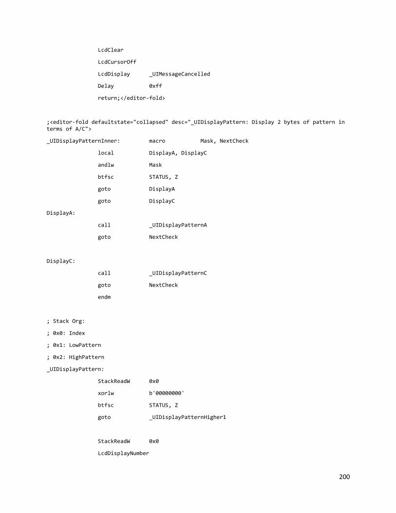
200
LcdClear
LcdCursorOff
LcdDisplay _UIMessageCancelled
Delay 0xff
return;</editor-fold>
;<editor-fold defaultstate="collapsed" desc="_UIDisplayPattern: Display 2 bytes of pattern in terms of A/C">
_UIDisplayPatternInner: macro Mask, NextCheck
local DisplayA, DisplayC
andlw Mask
btfsc STATUS, Z
goto DisplayA
goto DisplayC
DisplayA:
call _UIDisplayPatternA
goto NextCheck
DisplayC:
call _UIDisplayPatternC
goto NextCheck
endm
; Stack Org:
; 0x0: Index
; 0x1: LowPattern
; 0x2: HighPattern
_UIDisplayPattern:
StackReadW 0x0
xorlw b'00000000'
btfsc STATUS, Z
goto _UIDisplayPatternHigher1
StackReadW 0x0
LcdDisplayNumber

201
movlw d'46'
LcdDisplayW
_UIDisplayPatternHigher1:
StackReadF 0x2, TempW2
movfw TempW2
_UIDisplayPatternInner b'00010000', _UIDisplayPatternHigher2
_UIDisplayPatternHigher2:
movfw TempW2
_UIDisplayPatternInner b'00001000', _UIDisplayPatternHigher3
_UIDisplayPatternHigher3:
movfw TempW2
_UIDisplayPatternInner b'00000100', _UIDisplayPatternHigher4
_UIDisplayPatternHigher4:
movfw TempW2
_UIDisplayPatternInner b'00000010', _UIDisplayPatternHigher5
_UIDisplayPatternHigher5:
movfw TempW2
_UIDisplayPatternInner b'00000001', _UIDisplayPatternLower1
_UIDisplayPatternLower1:
StackReadF 0x1, TempW2
movfw TempW2
_UIDisplayPatternInner b'00010000', _UIDisplayPatternLower2
_UIDisplayPatternLower2:
movfw TempW2
_UIDisplayPatternInner b'00001000', _UIDisplayPatternLower3
_UIDisplayPatternLower3:
movfw TempW2

202
_UIDisplayPatternInner b'00000100', _UIDisplayPatternLower4
_UIDisplayPatternLower4:
movfw TempW2
_UIDisplayPatternInner b'00000010', _UIDisplayPatternLower5
_UIDisplayPatternLower5:
movfw TempW2
_UIDisplayPatternInner b'00000001', _UIDisplayPatternEnd
_UIDisplayPatternEnd:
return
_UIDisplayPatternA:
movlw d'65'
LcdDisplayW
return
_UIDisplayPatternC:
movlw d'67'
LcdDisplayW
return;</editor-fold>
end

203
UI.INC ;**********************************************************************
; UI Library
;**********************************************************************
ifndef _UIWelcome
extern _UIInit
extern _UIWelcome
;extern _UILoading
extern _UIFinished
extern _UIChipsLeft
extern _UIReadInput
extern _UIParseInputNumber
extern _UIWaitPond
extern _UIDisplayPattern
extern _UIMessageMachineName
endif
#define NumberValidatorH b'00100111'
#define NumberValidatorL b'01110111'
#define ACValidatorH b'00001000'
#define ACValidatorL b'00001000'
UIInit: macro
fcall _UIInit
endm
UIWelcome: macro
fcall _UIWelcome
endm
UIInitBottles: macro
fcall _UIInitBottles
endm
;UILoading: macro

204
; fcall _UILoading
; endm
UIFinished: macro
fcall _UIFinished
endm
UIChipsLeft: macro
fcall _UIChipsLeft
endm
UIReadInputAC: macro Length
StackInc
StackWriteL 0x0, Length
StackInc
StackWriteL 0x0, ACValidatorH
StackInc
StackWriteL 0x0, ACValidatorL
fcall _UIReadInput
StackDec 0x03
endm
UIReadInputNumber: macro Length
StackInc
StackWriteL 0x0, Length
StackInc
StackWriteL 0x0, NumberValidatorH
StackInc
StackWriteL 0x0, NumberValidatorL
fcall _UIReadInput
StackDec 0x03
endm

205
UIParseNumber: macro
fcall _UIParseInputNumber
endm
UIWaitPond: macro
fcall _UIWaitPond
endm
UICancel: macro
fcall _UICancel
endm
UIDisplayPattern: macro HighPattern, LowPattern, Index
StackPushL HighPattern
StackPushL LowPattern
StackPushL Index
fcall _UIDisplayPattern
StackDec 0x3
endm
UIDisplayPatternF: macro HighPatternF, LowPatternF, Index
StackInc
StackWriteF 0x0, HighPatternF
StackInc
StackWriteF 0x0, LowPatternF
StackPushL Index
fcall _UIDisplayPattern
StackDec 0x3
endm
; index in the working reg
UIDisplayPatternFF: macro HighPatternF, LowPatternF, IndexF
StackInc
StackWriteF 0x0, HighPatternF

206
StackInc
StackWriteF 0x0, LowPatternF
StackInc
StackWriteF 0x0, IndexF ; Index
fcall _UIDisplayPattern
StackDec 0x3
Endm
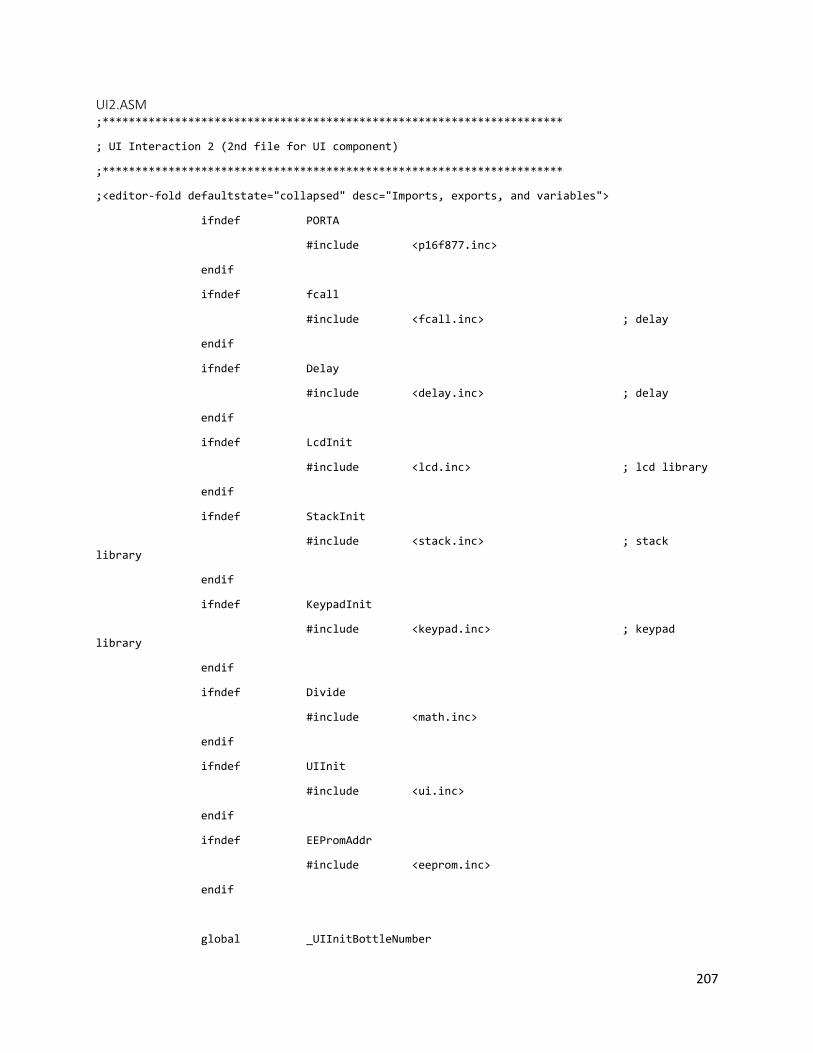
207
UI2.ASM ;**********************************************************************
; UI Interaction 2 (2nd file for UI component)
;**********************************************************************
;<editor-fold defaultstate="collapsed" desc="Imports, exports, and variables">
ifndef PORTA
#include <p16f877.inc>
endif
ifndef fcall
#include <fcall.inc> ; delay
endif
ifndef Delay
#include <delay.inc> ; delay
endif
ifndef LcdInit
#include <lcd.inc> ; lcd library
endif
ifndef StackInit
#include <stack.inc> ; stack library
endif
ifndef KeypadInit
#include <keypad.inc> ; keypad library
endif
ifndef Divide
#include <math.inc>
endif
ifndef UIInit
#include <ui.inc>
endif
ifndef EEPromAddr
#include <eeprom.inc>
endif
global _UIInitBottleNumber
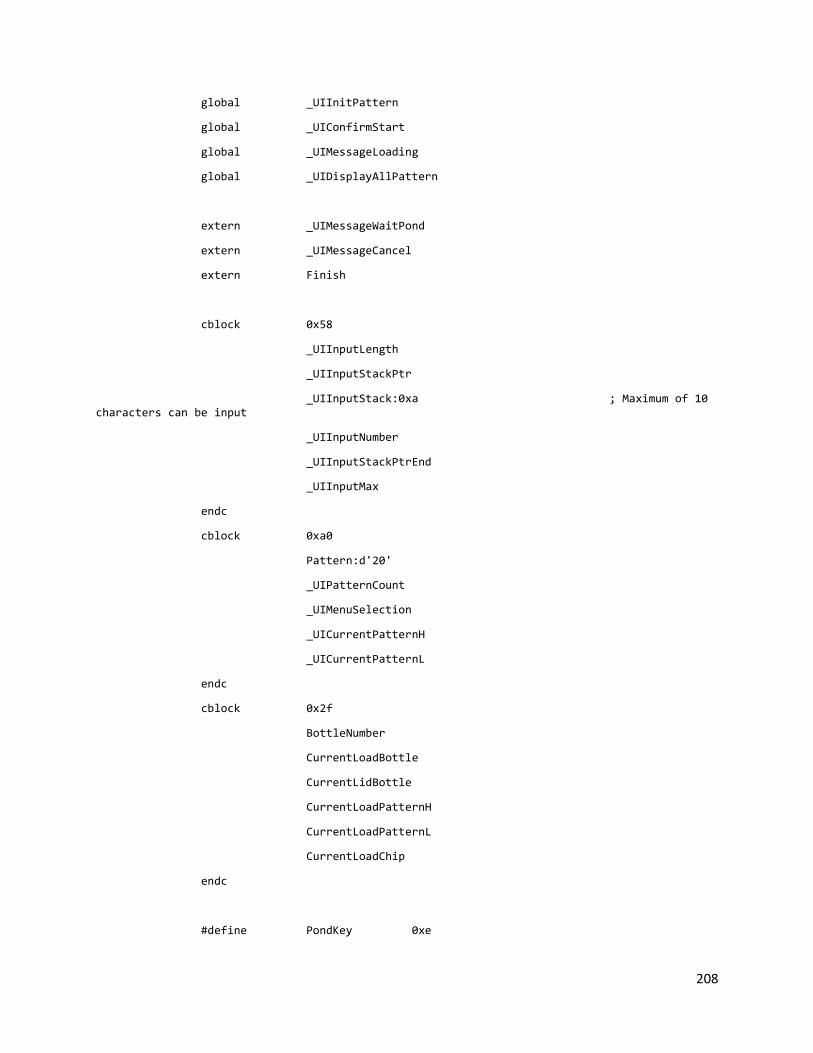
208
global _UIInitPattern
global _UIConfirmStart
global _UIMessageLoading
global _UIDisplayAllPattern
extern _UIMessageWaitPond
extern _UIMessageCancel
extern Finish
cblock 0x58
_UIInputLength
_UIInputStackPtr
_UIInputStack:0xa ; Maximum of 10 characters can be input
_UIInputNumber
_UIInputStackPtrEnd
_UIInputMax
endc
cblock 0xa0
Pattern:d'20'
_UIPatternCount
_UIMenuSelection
_UICurrentPatternH
_UICurrentPatternL
endc
cblock 0x2f
BottleNumber
CurrentLoadBottle
CurrentLidBottle
CurrentLoadPatternH
CurrentLoadPatternL
CurrentLoadChip
endc
#define PondKey 0xe

209
#define StarKey 0xc
#define CancelKey 0xf
;</editor-fold>
_UI2: code
;<editor-fold defaultstate="collapsed" desc="Built in messages">
_UIMessageAskBottleNumber:
dt "# of bottles:", 0
_UIMessageNumberTooLarge:
dt "Too large", 0
_UIMessageNumberTooSmall:
dt "Too small", 0
_UIMessagePatternTooShort:
dt "Pls enter 10", 0
_UIMessageAskPattern:
dt "Pattern for #", 0
_UIMessagePatternMenu:
dt "OK to view menu", 0
_UIMessagePatternMenu7:
dt "7.Custom", 0
_UIMessagePatternCustom:
dt "Enter A/C:", 0
_UIMessageLoading:
dt "Loading...", 0
;</editor-fold>
;<editor-fold defaultstate="collapsed" desc="_UIInitBottleNumber">
_UIInitBottleNumber:
LcdClear
LcdDisplay _UIMessageAskBottleNumber
LcdSwitchLine
LcdCursorOn
; Read input

210
UIReadInputNumber 0x2
LcdCursorOff
LcdClear
LcdSwitchLine
; Parse number
UIParseNumber
movfw _UIInputNumber
addlw -d'4'
btfss STATUS, C
goto _UIInitBottleNumberNext
LcdClear
LcdDisplay _UIMessageNumberTooLarge
Delay 0xff
goto _UIInitBottleNumber
_UIInitBottleNumberNext:
movfw _UIInputNumber
xorlw b'00000000'
btfss STATUS, Z
goto _UIInitBottleNumberNext2
LcdDisplay _UIMessageNumberTooSmall
Delay 0xff
goto _UIInitBottleNumber
_UIInitBottleNumberNext2:
movfw _UIInputNumber
banksel BottleNumber
movwf BottleNumber
;banksel PORTA
return
;</editor-fold>
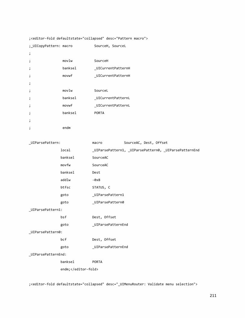
211
;<editor-fold defaultstate="collapsed" desc="Pattern macro">
;_UICopyPattern: macro SourceH, SourceL
;
; movlw SourceH
; banksel _UICurrentPatternH
; movwf _UICurrentPatternH
;
; movlw SourceL
; banksel _UICurrentPatternL
; movwf _UICurrentPatternL
; banksel PORTA
;
; endm
_UIParsePattern: macro SourceAC, Dest, Offset
local _UIParsePattern1, _UIParsePattern0, _UIParsePatternEnd
banksel SourceAC
movfw SourceAC
banksel Dest
addlw -0x8
btfsc STATUS, C
goto _UIParsePattern1
goto _UIParsePattern0
_UIParsePattern1:
bsf Dest, Offset
goto _UIParsePatternEnd
_UIParsePattern0:
bcf Dest, Offset
goto _UIParsePatternEnd
_UIParsePatternEnd:
banksel PORTA
endm;</editor-fold>
;<editor-fold defaultstate="collapsed" desc="_UIMenuRouter: Validate menu selection">
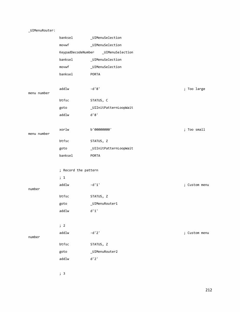
212
_UIMenuRouter:
banksel _UIMenuSelection
movwf _UIMenuSelection
KeypadDecodeNumber _UIMenuSelection
banksel _UIMenuSelection
movwf _UIMenuSelection
banksel PORTA
addlw -d'8' ; Too large menu number
btfsc STATUS, C
goto _UIInitPatternLoopWait
addlw d'8'
xorlw b'00000000' ; Too small menu number
btfsc STATUS, Z
goto _UIInitPatternLoopWait
banksel PORTA
; Record the pattern
; 1
addlw -d'1' ; Custom menu number
btfsc STATUS, Z
goto _UIMenuRouter1
addlw d'1'
; 2
addlw -d'2' ; Custom menu number
btfsc STATUS, Z
goto _UIMenuRouter2
addlw d'2'
; 3

213
addlw -d'3' ; Custom menu number
btfsc STATUS, Z
goto _UIMenuRouter3
addlw d'3'
; 4
addlw -d'4' ; Custom menu number
btfsc STATUS, Z
goto _UIMenuRouter4
addlw d'4'
; 5
addlw -d'5' ; Custom menu number
btfsc STATUS, Z
goto _UIMenuRouter5
addlw d'5'
; 6
addlw -d'6' ; Custom menu number
btfsc STATUS, Z
goto _UIMenuRouter6
addlw d'6'
; 7
addlw -d'7' ; Custom menu number
btfsc STATUS, Z
goto _UIInitPatternCustom
addlw d'7'
goto _UIInitPatternLoopEnd
_UIMenuRouter1:

214
EEPromReadA EEPromPattern1H
banksel _UICurrentPatternH
movwf _UICurrentPatternH
EEPromReadA EEPromPattern1L
banksel _UICurrentPatternL
movwf _UICurrentPatternL
banksel PORTA
goto _UIInitPatternLoopEnd
_UIMenuRouter2:
EEPromReadA EEPromPattern2H
banksel _UICurrentPatternH
movwf _UICurrentPatternH
EEPromReadA EEPromPattern2L
banksel _UICurrentPatternL
movwf _UICurrentPatternL
banksel PORTA
goto _UIInitPatternLoopEnd
_UIMenuRouter3:
EEPromReadA EEPromPattern3H
banksel _UICurrentPatternH
movwf _UICurrentPatternH
EEPromReadA EEPromPattern3L
banksel _UICurrentPatternL
movwf _UICurrentPatternL
banksel PORTA
goto _UIInitPatternLoopEnd
_UIMenuRouter4:
EEPromReadA EEPromPattern4H
banksel _UICurrentPatternH
movwf _UICurrentPatternH
EEPromReadA EEPromPattern4L
banksel _UICurrentPatternL
movwf _UICurrentPatternL
banksel PORTA
goto _UIInitPatternLoopEnd

215
_UIMenuRouter5:
EEPromReadA EEPromPattern5H
banksel _UICurrentPatternH
movwf _UICurrentPatternH
EEPromReadA EEPromPattern5L
banksel _UICurrentPatternL
movwf _UICurrentPatternL
banksel PORTA
goto _UIInitPatternLoopEnd
_UIMenuRouter6:
EEPromReadA EEPromPattern6H
banksel _UICurrentPatternH
movwf _UICurrentPatternH
EEPromReadA EEPromPattern6L
banksel _UICurrentPatternL
movwf _UICurrentPatternL
banksel PORTA
goto _UIInitPatternLoopEnd;</editor-fold>
;<editor-fold defaultstate="collapsed" desc="_UIInitPattern: Let user input the pattern for each bottle">
_UIInitPattern:
banksel _UIPatternCount
movlw 0x1 ; Make Count to start with 1
movwf _UIPatternCount
banksel PORTA
_UIInitPatternLoop:
banksel PORTA
LcdClear
LcdDisplay _UIMessageAskPattern
banksel _UIPatternCount
movfw _UIPatternCount
banksel PORTA
LcdDisplayNumber

216
movlw d'58'
LcdDisplayW
LcdSwitchLine
LcdCursorOff
LcdDisplay _UIMessagePatternMenu
_UIInitPatternLoopWait:
KeypadWaitChar
CheckKey PondKey, _UIInitPatternMenu1
CheckKey CancelKey, 0x0008
goto _UIMenuRouter
_UIInitPatternMenu1:
banksel PORTA
LcdClear
EEPromReadA EEPromPattern1H
banksel _UICurrentPatternH
movwf _UICurrentPatternH
EEPromReadA EEPromPattern1L
banksel _UICurrentPatternL
movwf _UICurrentPatternL
UIDisplayPatternF _UICurrentPatternH, _UICurrentPatternL, 0x1
banksel PORTA
LcdSwitchLine
EEPromReadA EEPromPattern2H
banksel _UICurrentPatternH
movwf _UICurrentPatternH
EEPromReadA EEPromPattern2L
banksel _UICurrentPatternL
movwf _UICurrentPatternL
UIDisplayPatternF _UICurrentPatternH, _UICurrentPatternL, 0x2
KeypadWaitChar

217
CheckKey PondKey, _UIInitPatternMenu2
CheckKey CancelKey, 0x0008
goto _UIMenuRouter
_UIInitPatternMenu2:
banksel PORTA
LcdClear
EEPromReadA EEPromPattern3H
banksel _UICurrentPatternH
movwf _UICurrentPatternH
EEPromReadA EEPromPattern3L
banksel _UICurrentPatternL
movwf _UICurrentPatternL
UIDisplayPatternF _UICurrentPatternH, _UICurrentPatternL, 0x3
banksel PORTA
LcdSwitchLine
EEPromReadA EEPromPattern4H
banksel _UICurrentPatternH
movwf _UICurrentPatternH
EEPromReadA EEPromPattern4L
banksel _UICurrentPatternL
movwf _UICurrentPatternL
UIDisplayPatternF _UICurrentPatternH, _UICurrentPatternL, 0x4
KeypadWaitChar
CheckKey PondKey, _UIInitPatternMenu3
CheckKey CancelKey, 0x0008
goto _UIMenuRouter
_UIInitPatternMenu3:
banksel PORTA
LcdClear
EEPromReadA EEPromPattern5H

218
banksel _UICurrentPatternH
movwf _UICurrentPatternH
EEPromReadA EEPromPattern5L
banksel _UICurrentPatternL
movwf _UICurrentPatternL
UIDisplayPatternF _UICurrentPatternH, _UICurrentPatternL, 0x5
banksel PORTA
LcdSwitchLine
EEPromReadA EEPromPattern6H
banksel _UICurrentPatternH
movwf _UICurrentPatternH
EEPromReadA EEPromPattern6L
banksel _UICurrentPatternL
movwf _UICurrentPatternL
UIDisplayPatternF _UICurrentPatternH, _UICurrentPatternL, 0x6
KeypadWaitChar
CheckKey PondKey, _UIInitPatternMenu4
CheckKey CancelKey, 0x0008
goto _UIMenuRouter
_UIInitPatternMenu4:
LcdClear
LcdDisplay _UIMessagePatternMenu7
KeypadWaitChar
CheckKey PondKey, _UIInitPatternMenu1
CheckKey CancelKey, 0x0008
goto _UIMenuRouter
_UIInitPatternCustom:
LcdClear
LcdDisplay _UIMessagePatternCustom

219
LcdCursorOn
LcdSwitchLine
UIReadInputAC 0xa
movfw _UIInputStackPtrEnd
sublw _UIInputStack
btfsc STATUS, Z
goto _UIInitPatternCustomParse
LcdClear
LcdCursorOff
LcdDisplay _UIMessagePatternTooShort
Delay 0xff
goto _UIInitPatternCustom
; Parse the custom pattern
_UIInitPatternCustomParse:
LcdCursorOff
banksel _UICurrentPatternH
clrf _UICurrentPatternH
clrf _UICurrentPatternL
_UIParsePattern _UIInputStackPtr+0x1, _UICurrentPatternL, 0x0
_UIParsePattern _UIInputStackPtr+0x2, _UICurrentPatternL, 0x1
_UIParsePattern _UIInputStackPtr+0x3, _UICurrentPatternL, 0x2
_UIParsePattern _UIInputStackPtr+0x4, _UICurrentPatternL, 0x3
_UIParsePattern _UIInputStackPtr+0x5, _UICurrentPatternL, 0x4
_UIParsePattern _UIInputStackPtr+0x6, _UICurrentPatternH, 0x0
_UIParsePattern _UIInputStackPtr+0x7, _UICurrentPatternH, 0x1
_UIParsePattern _UIInputStackPtr+0x8, _UICurrentPatternH, 0x2
_UIParsePattern _UIInputStackPtr+0x9, _UICurrentPatternH, 0x3
_UIParsePattern _UIInputStackPtr+0xa, _UICurrentPatternH, 0x4
_UIInitPatternLoopEnd:
LcdClear
LcdDisplay _UIMessageAskPattern
banksel _UIPatternCount
movfw _UIPatternCount

220
banksel PORTA
LcdDisplayNumber
movlw d'58'
LcdDisplayW
LcdSwitchLine
UIDisplayPatternF _UICurrentPatternH, _UICurrentPatternL, 0x0
Delay 0xff
_UIInitPatternLoopEnd2:
StackSave ; Save to designated register
banksel _UIPatternCount
rlf _UIPatternCount, w
addlw Pattern-0x2
movwf StackPtr
movff _UICurrentPatternH, Stack
incf StackPtr, f
movff _UICurrentPatternL, Stack
StackRestore
banksel _UIPatternCount ; Check if all bottles have been entered
movfw _UIPatternCount
banksel BottleNumber
subwf BottleNumber, w
btfsc STATUS, Z
goto _UIInitPatternEnd
banksel _UIPatternCount
incf _UIPatternCount, f
banksel PORTA
goto _UIInitPatternLoop
_UIInitPatternEnd:

221
; banksel CurrentLoadBottle
; clrf CurrentLoadBottle
; LcdClear
;DisplayAllPatternLoop:
; btfsc CurrentLoadBottle, 0
; goto LoopOdd
; goto LoopEven
;LoopOdd:
; LcdSwitchLine
; goto LoopNext
;LoopEven:
; LcdClear
; goto LoopNext
;LoopNext:
; StackSave
; banksel CurrentLoadBottle
; rlf CurrentLoadBottle, w
; banksel Pattern
; addlw Pattern
; movwf StackPtr
; movff Stack, CurrentLoadPatternH
; incf StackPtr, f
; movff Stack, CurrentLoadPatternL
; StackRestore
; banksel CurrentLoadBottle
; incf CurrentLoadBottle, f
; UIDisplayPatternFF CurrentLoadPatternH, CurrentLoadPatternL, CurrentLoadBottle
;
; Delay 0xff
; Delay 0xff
;
; banksel CurrentLoadBottle
; movfw CurrentLoadBottle
;

222
; banksel BottleNumber
; subwf BottleNumber, w
; btfss STATUS, Z
; goto DisplayAllPatternLoop
;
; banksel CurrentLoadBottle
; clrf CurrentLoadBottle
; banksel PORTA
return
;</editor-fold>
;<editor-fold defaultstate="collapsed" desc="_UIConfirmStart: Let user to confirm start or cancel">
_UIConfirmStart:
LcdClear
LcdDisplay _UIMessageWaitPond
LcdSwitchLine
LcdDisplay _UIMessageCancel
_UIConfirmStartWait:
KeypadWaitChar
CheckKey PondKey, _UIConfirmStartYes
CheckKey CancelKey, _UIConfirmStartNo
goto _UIConfirmStartWait
_UIConfirmStartYes:
retlw 0x1
_UIConfirmStartNo:
retlw 0x0
;</editor-fold>
;<editor-fold defaultstate="collapsed" desc="_UIDisplayAllPattern: Display all the pattern information at the end of the operation">
_UIDisplayAllPattern:

223
banksel CurrentLoadBottle
clrf CurrentLoadBottle
LcdClear
DisplayAllPatternLoop:
btfsc CurrentLoadBottle, 0
goto LoopOdd
goto LoopEven
LoopOdd:
LcdSwitchLine
goto LoopNext
LoopEven:
LcdClear
goto LoopNext
LoopNext:
StackSave
banksel CurrentLoadBottle
bcf STATUS, C
rlf CurrentLoadBottle, w
banksel Pattern
addlw Pattern
movwf StackPtr
movff Stack, CurrentLoadPatternH
incf StackPtr, f
movff Stack, CurrentLoadPatternL
StackRestore
banksel CurrentLoadBottle
incf CurrentLoadBottle, f
UIDisplayPatternFF CurrentLoadPatternH, CurrentLoadPatternL, CurrentLoadBottle
Delay 0xff
Delay 0xff
banksel CurrentLoadBottle
movfw CurrentLoadBottle

224
banksel BottleNumber
subwf BottleNumber, w
btfss STATUS, Z
goto DisplayAllPatternLoop
banksel CurrentLoadBottle
clrf CurrentLoadBottle
banksel PORTA
return;</editor-fold>
end

225
UI2.INC ifndef _UIInitBottleNumber
extern _UIInitBottleNumber
extern _UIInitPattern
extern _UIConfirmStart
extern _UICancel
extern _UIDisplayAllPattern
endif
UIInitBottleNumber: macro
fcall _UIInitBottleNumber
endm
UIInitPattern: macro
fcall _UIInitPattern
endm
UIConfirmStart: macro Run, Cancel
fcall _UIConfirmStart
xorlw b'00000000'
btfsc STATUS, Z
goto Cancel
goto Run
endm
UIDisplayAllPattern: macro
fcall _UIDisplayAllPattern
endm

226
13.3.3 PC INTERFACE ORIGINAL SOURCE CODE Note: for entire solution folder and code, please ask for a digital copy. Only important code are shown
here to save the space.
PICUSB2.CS using System; using System.Collections.Generic; using System.ComponentModel; using System.Data; using System.Drawing; using System.IO; using System.Text; using System.Windows.Forms; namespace PICusb { public partial class PicUsb2 : Form { private FormPICusb MainForm { get; set; } private List<LogEntry> Logs { get; set; } private int Selected { get; set; } public PicUsb2(FormPICusb form1) { this.MainForm = form1; InitializeComponent(); this.Selected = -1; this.button2.Enabled = false; } private class LogEntry { public DateTime StartTime { get; set; } public TimeSpan Duration { get; set; } public int BottleNumber { get; set; } public int ChipsLeftA { get; set; } public int ChipsLeftC { get; set; } public bool Success { get; set; } public List<Pattern> Patterns { get; set; } public int Length { get; set; } public override string ToString() { StringBuilder sb = new StringBuilder(); sb.Append(String.Format("Time: {0}{1}", StartTime, Environment.NewLine)); sb.Append(String.Format("Duration: {0}{1}", Duration, Environment.NewLine)); sb.Append(String.Format("Status: {0}{1}", Success ? "Successful" : "Failed", Environment.NewLine)); sb.Append(String.Format("Number of containers: {0}{1}", BottleNumber, Environment.NewLine)); sb.Append(String.Format("Chips left A: {0}, C: {1}{2}", ChipsLeftA, ChipsLeftC, Environment.NewLine)); sb.Append(String.Format("Container information:{0}", Environment.NewLine)); for (int i = 0; i < Patterns.Count; i++) { sb.Append(String.Format("Container {0}: {1}{2}", i + 1, Patterns[i].ACPattern, Environment.NewLine));
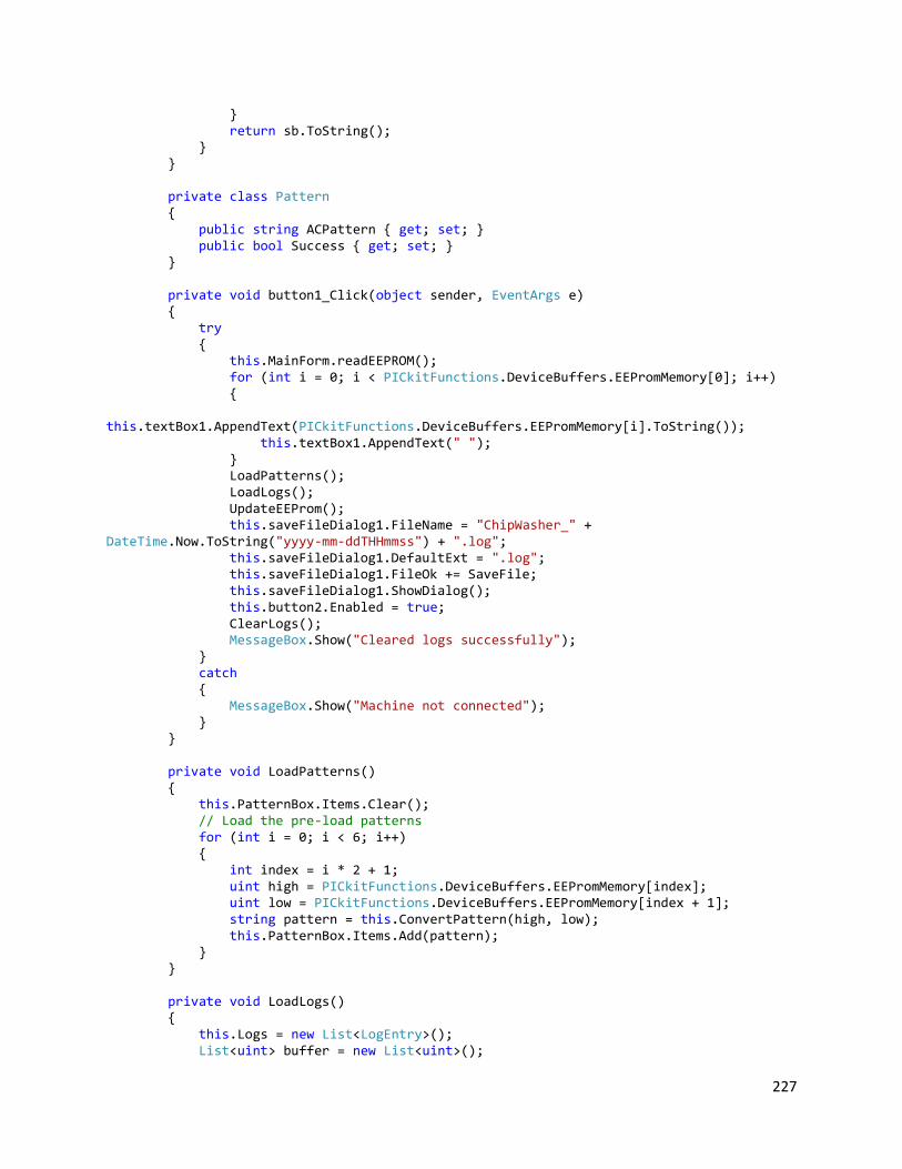
227
} return sb.ToString(); } } private class Pattern { public string ACPattern { get; set; } public bool Success { get; set; } } private void button1_Click(object sender, EventArgs e) { try { this.MainForm.readEEPROM(); for (int i = 0; i < PICkitFunctions.DeviceBuffers.EEPromMemory[0]; i++) { this.textBox1.AppendText(PICkitFunctions.DeviceBuffers.EEPromMemory[i].ToString()); this.textBox1.AppendText(" "); } LoadPatterns(); LoadLogs(); UpdateEEProm(); this.saveFileDialog1.FileName = "ChipWasher_" + DateTime.Now.ToString("yyyy-mm-ddTHHmmss") + ".log"; this.saveFileDialog1.DefaultExt = ".log"; this.saveFileDialog1.FileOk += SaveFile; this.saveFileDialog1.ShowDialog(); this.button2.Enabled = true; ClearLogs(); MessageBox.Show("Cleared logs successfully"); } catch { MessageBox.Show("Machine not connected"); } } private void LoadPatterns() { this.PatternBox.Items.Clear(); // Load the pre-load patterns for (int i = 0; i < 6; i++) { int index = i * 2 + 1; uint high = PICkitFunctions.DeviceBuffers.EEPromMemory[index]; uint low = PICkitFunctions.DeviceBuffers.EEPromMemory[index + 1]; string pattern = this.ConvertPattern(high, low); this.PatternBox.Items.Add(pattern); } } private void LoadLogs() { this.Logs = new List<LogEntry>(); List<uint> buffer = new List<uint>();
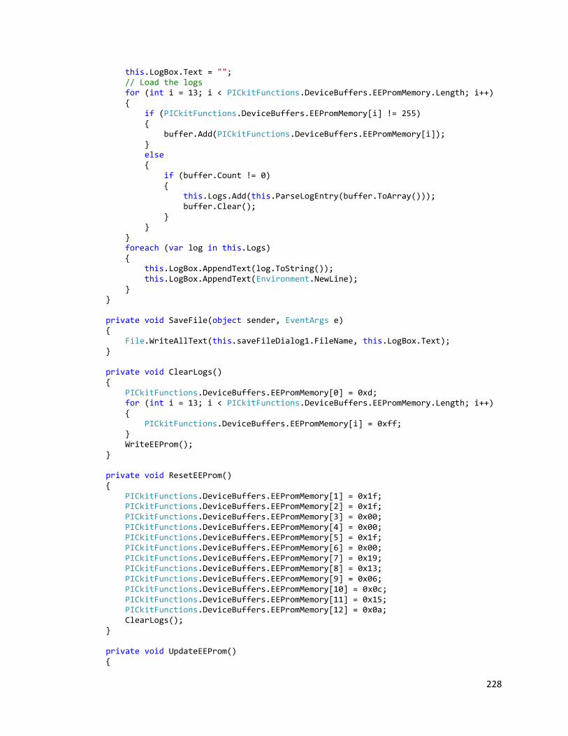
228
this.LogBox.Text = ""; // Load the logs for (int i = 13; i < PICkitFunctions.DeviceBuffers.EEPromMemory.Length; i++) { if (PICkitFunctions.DeviceBuffers.EEPromMemory[i] != 255) { buffer.Add(PICkitFunctions.DeviceBuffers.EEPromMemory[i]); } else { if (buffer.Count != 0) { this.Logs.Add(this.ParseLogEntry(buffer.ToArray())); buffer.Clear(); } } } foreach (var log in this.Logs) { this.LogBox.AppendText(log.ToString()); this.LogBox.AppendText(Environment.NewLine); } } private void SaveFile(object sender, EventArgs e) { File.WriteAllText(this.saveFileDialog1.FileName, this.LogBox.Text); } private void ClearLogs() { PICkitFunctions.DeviceBuffers.EEPromMemory[0] = 0xd; for (int i = 13; i < PICkitFunctions.DeviceBuffers.EEPromMemory.Length; i++) { PICkitFunctions.DeviceBuffers.EEPromMemory[i] = 0xff; } WriteEEProm(); } private void ResetEEProm() { PICkitFunctions.DeviceBuffers.EEPromMemory[1] = 0x1f; PICkitFunctions.DeviceBuffers.EEPromMemory[2] = 0x1f; PICkitFunctions.DeviceBuffers.EEPromMemory[3] = 0x00; PICkitFunctions.DeviceBuffers.EEPromMemory[4] = 0x00; PICkitFunctions.DeviceBuffers.EEPromMemory[5] = 0x1f; PICkitFunctions.DeviceBuffers.EEPromMemory[6] = 0x00; PICkitFunctions.DeviceBuffers.EEPromMemory[7] = 0x19; PICkitFunctions.DeviceBuffers.EEPromMemory[8] = 0x13; PICkitFunctions.DeviceBuffers.EEPromMemory[9] = 0x06; PICkitFunctions.DeviceBuffers.EEPromMemory[10] = 0x0c; PICkitFunctions.DeviceBuffers.EEPromMemory[11] = 0x15; PICkitFunctions.DeviceBuffers.EEPromMemory[12] = 0x0a; ClearLogs(); } private void UpdateEEProm() {
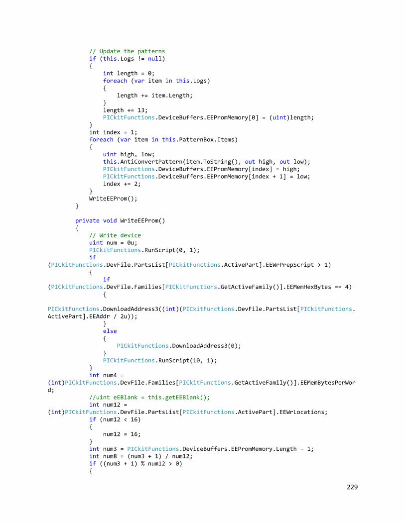
229
// Update the patterns if (this.Logs != null) { int length = 0; foreach (var item in this.Logs) { length += item.Length; } length += 13; PICkitFunctions.DeviceBuffers.EEPromMemory[0] = (uint)length; } int index = 1; foreach (var item in this.PatternBox.Items) { uint high, low; this.AntiConvertPattern(item.ToString(), out high, out low); PICkitFunctions.DeviceBuffers.EEPromMemory[index] = high; PICkitFunctions.DeviceBuffers.EEPromMemory[index + 1] = low; index += 2; } WriteEEProm(); } private void WriteEEProm() { // Write device uint num = 0u; PICkitFunctions.RunScript(0, 1); if (PICkitFunctions.DevFile.PartsList[PICkitFunctions.ActivePart].EEWrPrepScript > 1) { if (PICkitFunctions.DevFile.Families[PICkitFunctions.GetActiveFamily()].EEMemHexBytes == 4) { PICkitFunctions.DownloadAddress3((int)(PICkitFunctions.DevFile.PartsList[PICkitFunctions.ActivePart].EEAddr / 2u)); } else { PICkitFunctions.DownloadAddress3(0); } PICkitFunctions.RunScript(10, 1); } int num4 = (int)PICkitFunctions.DevFile.Families[PICkitFunctions.GetActiveFamily()].EEMemBytesPerWord; //uint eEBlank = this.getEEBlank(); int num12 = (int)PICkitFunctions.DevFile.PartsList[PICkitFunctions.ActivePart].EEWrLocations; if (num12 < 16) { num12 = 16; } int num3 = PICkitFunctions.DeviceBuffers.EEPromMemory.Length - 1; int num8 = (num3 + 1) / num12; if ((num3 + 1) % num12 > 0) {

230
num8++; } num3 = num8 * num12; byte[] array2 = new byte[num12 * num4]; int repetitions = num12 / (int)PICkitFunctions.DevFile.PartsList[PICkitFunctions.ActivePart].EEWrLocations; int num13 = 0; do { int num9 = 0; for (int j = 0; j < num12; j++) { uint num14 = PICkitFunctions.DeviceBuffers.EEPromMemory[num13++]; if (PICkitFunctions.DevFile.Families[PICkitFunctions.GetActiveFamily()].ProgMemShift > 0) { num14 <<= 1; } array2[num9++] = (byte)(num14 & 255u); num += (uint)((byte)(num14 & 255u)); for (int k = 1; k < num4; k++) { num14 >>= 8; array2[num9++] = (byte)(num14 & 255u); num += (uint)((byte)(num14 & 255u)); } } PICkitFunctions.DataClrAndDownload(array2, 0); PICkitFunctions.RunScript(11, repetitions); } while (num13 < num3); PICkitFunctions.RunScript(1, 1); } private string ConvertPattern(uint high, uint low) { string result = ""; uint mask = 0x10; for (int i = 0; i < 5; i++) { if ((high & mask) != 0) { result += "C"; } else { result += "A"; } mask = mask >> 1; } mask = 0x10; for (int i = 0; i < 5; i++) { if ((low & mask) != 0) { result += "C"; } else

231
{ result += "A"; } mask = mask >> 1; } return result; } private int ConvertDate(uint hexDate) { int ten, one; ten = ((int)hexDate & 0xf0) / 0x10; one = ((int)hexDate & 0x0f); return ten * 10 + one; } private LogEntry ParseLogEntry(uint[] raw) { LogEntry result = new LogEntry(); int year = this.ConvertDate(raw[0]) + 2000; int month = this.ConvertDate(raw[1]); int day = this.ConvertDate(raw[2]); int hour = this.ConvertDate(raw[3]); int minute = this.ConvertDate(raw[4]); int second = this.ConvertDate(raw[5]); result.StartTime = new DateTime(year, month, day, hour, minute, second); int minute2 = (int)raw[6]; int second2 = (int)raw[7]; result.Duration = new TimeSpan(0, minute2, second2); if (raw[8] > 128) { result.Success = true; result.BottleNumber = (int)raw[8] - 128; } else { result.Success = false; result.BottleNumber = (int)raw[8]; } result.ChipsLeftA = (int)raw[9]; result.ChipsLeftC = (int)raw[10]; result.Patterns = new List<Pattern>(); for (int i = 11; i < raw.Length; i = i + 2) { Pattern pattern = new Pattern(); uint high, low; if (raw[i] >= 128) { pattern.Success = true; high = raw[i] - 128; } else { pattern.Success = false; high = raw[i]; } low = raw[i + 1]; pattern.ACPattern = this.ConvertPattern(high, low);

232
result.Patterns.Add(pattern); } result.Length = raw.Length + 1; return result; } private void AntiConvertPattern(string pattern, out uint high, out uint low) { int mask = 0x10; high = 0; low = 0; foreach (char c in pattern.Substring(0, 5)) { if (c == 'C') { high += (uint)mask; } mask = mask >> 1; } mask = 0x10; foreach (char c in pattern.Substring(5, 5)) { if (c == 'C') { low += (uint)mask; } mask = mask >> 1; } } private void listBox1_SelectedIndexChanged(object sender, EventArgs e) { if (this.PatternBox.SelectedIndex != -1 && this.PatternBox.SelectedIndex != this.Selected) { this.Selected = this.PatternBox.SelectedIndex; string pattern = this.PatternBox.Items[this.PatternBox.SelectedIndex].ToString(); string replace = Microsoft.VisualBasic.Interaction.InputBox("Enter pattern to replace", "Replace pre-loaded pattern", pattern, 0, 0); if (replace.Length != 10) { return; } foreach (char c in replace) { if (c != 'C' && c != 'A') { MessageBox.Show("Invalid pattern"); return; } } this.PatternBox.Items[this.PatternBox.SelectedIndex] = replace; } } private void button2_Click(object sender, EventArgs e) {

233
try { this.UpdateEEProm(); MessageBox.Show("Updated device successfully"); } catch { MessageBox.Show("Machine not connected"); } } private void button3_Click(object sender, EventArgs e) { try { ResetEEProm(); MessageBox.Show("Reset device successfully"); } catch { MessageBox.Show("Machine not connected"); } } } }

234
PICUSB.DESIGNER.CS namespace PICusb { partial class PicUsb2 { /// <summary> /// Required designer variable. /// </summary> private System.ComponentModel.IContainer components = null; /// <summary> /// Clean up any resources being used. /// </summary> /// <param name="disposing">true if managed resources should be disposed; otherwise, false.</param> protected override void Dispose(bool disposing) { if (disposing && (components != null)) { components.Dispose(); } base.Dispose(disposing); } #region Windows Form Designer generated code /// <summary> /// Required method for Designer support - do not modify /// the contents of this method with the code editor. /// </summary> private void InitializeComponent() { System.ComponentModel.ComponentResourceManager resources = new System.ComponentModel.ComponentResourceManager(typeof(PicUsb2)); this.button1 = new System.Windows.Forms.Button(); this.textBox1 = new System.Windows.Forms.TextBox(); this.button2 = new System.Windows.Forms.Button(); this.PatternBox = new System.Windows.Forms.ListBox(); this.LogBox = new System.Windows.Forms.TextBox(); this.saveFileDialog1 = new System.Windows.Forms.SaveFileDialog(); this.groupBox1 = new System.Windows.Forms.GroupBox(); this.groupBox2 = new System.Windows.Forms.GroupBox(); this.button3 = new System.Windows.Forms.Button(); this.groupBox1.SuspendLayout(); this.groupBox2.SuspendLayout(); this.SuspendLayout(); // // button1 // this.button1.Location = new System.Drawing.Point(393, 28); this.button1.Name = "button1"; this.button1.Size = new System.Drawing.Size(97, 25); this.button1.TabIndex = 0; this.button1.Text = "Download"; this.button1.UseVisualStyleBackColor = true; this.button1.Click += new System.EventHandler(this.button1_Click); //

235
// textBox1 // this.textBox1.Location = new System.Drawing.Point(106, 253); this.textBox1.Multiline = true; this.textBox1.Name = "textBox1"; this.textBox1.Size = new System.Drawing.Size(374, 53); this.textBox1.TabIndex = 1; // // button2 // this.button2.Location = new System.Drawing.Point(393, 59); this.button2.Name = "button2"; this.button2.Size = new System.Drawing.Size(97, 25); this.button2.TabIndex = 2; this.button2.Text = "Update"; this.button2.UseVisualStyleBackColor = true; this.button2.Click += new System.EventHandler(this.button2_Click); // // PatternBox // this.PatternBox.FormattingEnabled = true; this.PatternBox.Location = new System.Drawing.Point(6, 17); this.PatternBox.Name = "PatternBox"; this.PatternBox.Size = new System.Drawing.Size(85, 199); this.PatternBox.TabIndex = 3; this.PatternBox.SelectedIndexChanged += new System.EventHandler(this.listBox1_SelectedIndexChanged); // // LogBox // this.LogBox.Location = new System.Drawing.Point(7, 17); this.LogBox.Multiline = true; this.LogBox.Name = "LogBox"; this.LogBox.ScrollBars = System.Windows.Forms.ScrollBars.Vertical; this.LogBox.Size = new System.Drawing.Size(250, 198); this.LogBox.TabIndex = 7; // // groupBox1 // this.groupBox1.Controls.Add(this.LogBox); this.groupBox1.Location = new System.Drawing.Point(120, 12); this.groupBox1.Name = "groupBox1"; this.groupBox1.Size = new System.Drawing.Size(265, 222); this.groupBox1.TabIndex = 8; this.groupBox1.TabStop = false; this.groupBox1.Text = "Machine Logs"; // // groupBox2 // this.groupBox2.Controls.Add(this.PatternBox); this.groupBox2.Location = new System.Drawing.Point(12, 12); this.groupBox2.Name = "groupBox2"; this.groupBox2.Size = new System.Drawing.Size(98, 222); this.groupBox2.TabIndex = 9; this.groupBox2.TabStop = false; this.groupBox2.Text = "Patterns"; // // button3

236
// this.button3.Location = new System.Drawing.Point(391, 90); this.button3.Name = "button3"; this.button3.Size = new System.Drawing.Size(97, 25); this.button3.TabIndex = 12; this.button3.Text = "Reset"; this.button3.UseVisualStyleBackColor = true; this.button3.Click += new System.EventHandler(this.button3_Click); // // PicUsb2 // this.AutoScaleDimensions = new System.Drawing.SizeF(6F, 13F); this.AutoScaleMode = System.Windows.Forms.AutoScaleMode.Font; this.ClientSize = new System.Drawing.Size(500, 240); this.Controls.Add(this.button3); this.Controls.Add(this.groupBox2); this.Controls.Add(this.groupBox1); this.Controls.Add(this.button2); this.Controls.Add(this.textBox1); this.Controls.Add(this.button1); this.Icon = ((System.Drawing.Icon)(resources.GetObject("$this.Icon"))); this.MaximizeBox = false; this.MaximumSize = new System.Drawing.Size(516, 279); this.MinimizeBox = false; this.MinimumSize = new System.Drawing.Size(516, 279); this.Name = "PicUsb2"; this.Text = "Chip Washer PC Terminal"; this.groupBox1.ResumeLayout(false); this.groupBox1.PerformLayout(); this.groupBox2.ResumeLayout(false); this.ResumeLayout(false); this.PerformLayout(); } #endregion private System.Windows.Forms.Button button1; private System.Windows.Forms.TextBox textBox1; private System.Windows.Forms.Button button2; private System.Windows.Forms.ListBox PatternBox; private System.Windows.Forms.TextBox LogBox; private System.Windows.Forms.SaveFileDialog saveFileDialog1; private System.Windows.Forms.GroupBox groupBox1; private System.Windows.Forms.GroupBox groupBox2; private System.Windows.Forms.Button button3; } }
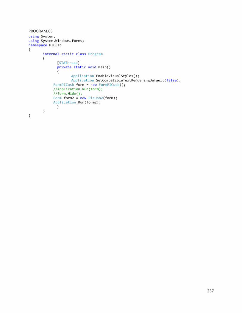
237
PROGRAM.CS using System; using System.Windows.Forms; namespace PICusb { internal static class Program { [STAThread] private static void Main() { Application.EnableVisualStyles(); Application.SetCompatibleTextRenderingDefault(false); FormPICusb form = new FormPICusb(); //Application.Run(form); //form.Hide(); Form form2 = new PicUsb2(form); Application.Run(form2); } } }