chiral metamaterial based multifunctional sensor …jpier.org/pier/pier149/04.14070111.pdf ·...
TRANSCRIPT

Progress In Electromagnetics Research, Vol. 149, 55–67, 2014
Chiral Metamaterial Based Multifunctional Sensor Applications
Muharrem Karaaslan and Mehmet Bakir*
Abstract—In this work, sensor abilities of a chiral metamaterial based on split ring resonators withdouble splits (SRDS) are demonstrated both theoretically and experimentally in X band range. Thisstudy is based on transmission measurements and simulations monitoring the resonance frequencychanges with respect to the thickness of the sensing layer and permittivity values. Experimental andsimulated results show that the resonance frequency of the chiral metamaterial based SRDS sensoris linearly related to the permittivity and the thickness of the sensor layer which creates a suitableapproach for sensing environment and organic parameters. When the sensor layer filled with therelated material, changes in the tissue temperature, sand humidity and calcium chloride density lead toresonance frequency changes. The physical mechanisms are explained by using both equivalent circuitmodel and the fundamental sensitivity theorem of chiral sensors. This is the first study investigating asensing mechanism based on the chiral metamaterials in X band range.
1. INTRODUCTION
Researchers produce an artificial micro-sized medium such as left-handed materials (LHMs) by usingmicro- and nano-fabrication techniques in order to manage electromagnetic (EM) waves in controllableway. LHMs, a subset of the metamaterials, are based on arrays of classical plasmonic resonators whichhave been designed to acquire simultaneous negative permittivity and negative permeability valuesproviding negative refraction. The LHMs are man-made materials showing extraordinary characteristicsthat cannot be found in nature [1, 2]. In this case, a split-ring resonator (SRR) structure which hasbeen used more than a decade in order to produce magnetic response in various types of metamaterialsfrom microwave to optical region is artificially produced. The SRR type metamaterials can be usedto create strong magnetic coupling among the EM fields which cannot be available in conventionalmethods. There are some studies realizing magnetic resonances by using different SRR configurationsin literature [3–12]. SRR topology consists of more than one coupled SRR unit cell. This feature providesmutual inductance and capacitance effects at the resonance frequency according to their positions [13].
In a chiral medium, an electric field causes magnetic polarization, and a magnetic field induces anelectrical polarization which is defined as magneto-electric coupling [14]. When a metamaterial involveschiral inclusions, it can be considered as a chiral metamaterial meaning that the effective chiralityadmittance (ζ) is non-zero. Wave propagation properties in a chiral metamaterials demonstrate thatthe negative refraction can be obtained with a strong chirality without requiring negative ε or μ [15, 16].
Metamaterial studies have reached an advanced level due to a continual progress in design andfabrication of metamaterials on micro- and nano-scale levels. Due to the relation between metamaterialscience and sensing technology, new scientific and technological applications have been developed inthis particular field. Furthermore, considerable advances have been realized on the metamaterial basedsensors which lead to detecting information of a substance and a situation. The metamaterial basedsensors which generally have SRRs are developed for the observation of environmental parameters
Received 1 July 2014, Accepted 14 August 2014, Scheduled 28 August 2014* Corresponding author: Mehmet Bakir ([email protected]).The authors are with the Department of Electrical and Electronics Engineering, Mustafa Kemal University, Iskenderun, Hatay 31200,Turkey.
56 Karaaslan and Bakir
because of their resonance frequencies since the environmental parameters change the resonancefrequencies.
Sensors have to meet some requirements in order to work effectively. For example, they musthave a loss factor as low as possible to prevent substrate absorption. Hence, we have chosen a polyesterlaminate GML 1000 type substrate material with a loss tangent of 0.004. Secondly, the sensors must givea measurable signal according to the changes in the parameters. The third one is the linearity meaningthat the sensor must shift the resonance frequency sharply or smoothly according to the quantity of thechanges in the observed parameter. The fourth one is the sensor sensitivity. If the sensitivity is high,related shifts can easily be observed from the network analyzer.
These suggested requirements are considered and realized in this study to obtain a new sensorbased on a chiral metamaterial designed by square-ring with double splits (SRDS) which have highefficiency and gain. There are many advantages of the proposed study compared to the metamaterialbased sensor studies in literature. The reason is that this study takes advantages of chiral metamaterialswhich have some unusual EM features such as optical activity, negative refraction, etc. [17, 18]. Thesuggested SRDS-shaped resonator based on chiral metamaterial introduces an alternative and newapproach to the sensor applications. These advantages are discussed and verified both experimentallyand numerically. Theoretical and experimental analysis of the proposed sensor application is realizedin detail.
The organization of this study is as follows. In Section 2, the design of the chiral unit cell isexplained. In Section 3, an experiment and a simulation of the chiral MTMs based on discontinuousbilayer cross-wires structure are proposed. The experiment and simulation methods are introduced. InSection 4, a chiral metamaterial based pressure sensor application together with the idea of using theresonance frequency change in a sensor is substantiated. In Section 5, generalization of the idea and thedesign of chiral structures are presented. In Section 6, a chiral metamaterial based sensor applicationis demonstrated. Finally, summary and conclusions are given at the end of the paper.
2. DESIGN OF THE CHIRAL UNIT CELL
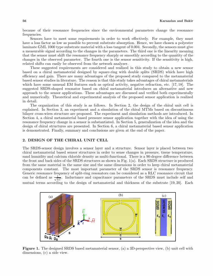
The SRDS-sensor design involves a sensor layer and a structure. Sensor layer is placed between twochiral metamaterial based sensor structures in order to sense changes in pressure, tissue temperature,sand humidity and calcium chloride density as multi-functional. There is a 90-degree difference betweenthe front and back sides of the SRDS structures as shown in Fig. 1(a). Each SRDS structure is producedfrom the same material in the same size and the same dimensions in order to keep chiral metamaterialcomponents constant. The most important parameter of the SRDS sensor is resonance frequency.Generic resonance frequency of split-ring resonators can be considered as a RLC resonance circuit thatcan be defined as 1√
LC. Inductance and capacitance parameters of the SRDS must include self and
mutual terms according to the design of metamaterial and thickness of the substrate [19, 20]. Each
(a) (b) (c)
Figure 1. The designed SRDS based metamaterial sensor, (a) a 3D-perspective view, (b) unit cell withdimensions, (c) a side view.

Progress In Electromagnetics Research, Vol. 149, 2014 57
SRDS structure is placed opposite sides of the unit cell to create powerful coupling. We designedthe SRDS structure not only to meet the sensor requirements explained before but also to increasesensitivity in different sensing areas for physical and biological applications. In this study, the substrateand metal thickness of SRDS structures are kept fixed to monitor the changes between the sensor layerpermittivity (εi) and the resonance frequency. The Sensor layer is going to be used for sensing thechanges of the environmental parameters. In this study, the effects of the changes in thickness of thesensing layer (gi) and dielectric constant of the sensing layer (εi) have been used effectively for sensingenvironmental parameters as to be demonstrated in the rest of the paper.
We have two identical SRDS structures which are placed in a unit cell with 90◦ difference in order toachieve asymmetry. This asymmetry of the structure provides both chirality and rotated electromagneticwave composed of right- and left-hand circularly polarized parts. Hence, it will contribute strongersensing of sandwiched dielectric layer with respect to the metamaterial based sensors [21]. The SRDSstructures are printed on a polyester laminate GML 1000 type substrate material due to its low losscharacteristics. The GML 1000 material has dielectric constant of εs = 3.05, loss tangent of ζ = 0.004 at10 GHz with a substrate thickness of gs = 0.5mm. One side of GML 1000 is coated with SRDS inclusionsto provide surface current. Copper thickness and conductivity are 0.035 mm and σcu = 58 × 106 S/m,respectively. SRDS unit cell has the following dimensions: substrate with width s = 4.5mm, copperlength c = 4mm, gap between the square and circle strip w = 0.15mm as shown in Fig. 1(b). Theseparameters are kept constant during the simulations and the experiments for all suggested sensor types.The SRDS structures are separated from each other by a sensing layer. The sensing layer is definedwith a variable thickness value of gi and a dielectric constant of εi to determine the sensitivity of thestructure with respect to the changes in density and pressure as shown in Fig. 1(c).
3. SIMULATION AND EXPERIMENTAL SETUP
The proposed SRDS sensor can be used to sense different parameters according to the changes indielectric constant and thickness of sensing layer which are investigated numerically and experimentallyin the following sections. The fabricated SRDS structure is given in Fig. 2(a). We investigate theperformance of the SRDS based chiral metamaterial sensor as a density and a pressure sensors bothnumerically and experimentally. In addition, humidity, temperature and density sensors are alsoinvestigated numerically as can be seen in the following sections.
In the experimental setup, two-port rectangular waveguide has been used for sensing applicationsbetween 8–12 GHz as shown in Fig. 2(b). Two ports are connected to the vector network analyzer(VNA) by using two waveguide adapters. Complex values of reflection and transmission parameters(S-parameters) have been both simulated and measured for the SRDS sensor via finite integrationtechnique based simulator (CST Microwave Studio) and the network analyzer, respectively. The
Figure 2. (a) An image of front side of the SRDS sample fabricated in microwave scale, (b) measurementsetup of the sample.

58 Karaaslan and Bakir
analyzer is calibrated before SRDS measurement accordingly to achieve accurate results. TheSRDS sensor structure is placed at the bottom of the calibrated waveguide to provide appropriateinteraction. Fabricated SRDS sensor structure is fixed in the unit cell by a sample holder to realizeaccurate measurement. Sample holder’s permittivity and permeability values are very close to the air(μr
∼= 1, εr∼= 1) to prevent undesired interaction. As a result, the sensor holder does not influence
measurements by undesirable reflection or absorptions. TE10 waveguide mode has been used for theexperiments, hence the resonance of the overall structure is provided due to the propagation of magneticfield component of the incident wave through the center of SRDS unit cell.
CST Microwave studio has been used for the numerical simulations described in this study.Conducting wall type boundary conditions are applied in X and Y directions while open boundarycondition is applied in Z direction in order to match simulation and experimental results. Duringsimulation, port 1 and port 2 dimensions are adjusted according to the waveguide volume and dimensionsin order to achieve accurate simulations. After necessary adjustments, both numerical and experimentalresults are matched. CST microwave studio efficiently simulates two-dimensional SRDS structure inxy-plane. Because of the larger dimensions of the X band waveguide, SRDS structure is quite small buthighly effective in this study. The SRDS unit cell behaves as periodically arranged two-dimensionalSRDS arrays due to the assignment of the conducting walls in x-y planes, since conducting wallboundaries provide imaging effect on the unit cell. Consequently, coupling between the unit cells ofthis array can also be neglected because of the mirror behavior of waveguide walls and electromagneticcharacteristics of unit cell array getting closer to a periodic array of a unit cell. Measurement results ofa single cell and in the waveguide and measurement results that can be realized in free space for sensorwhich has more than a single cell would be similar to each other. This measurement technique for aunit cell in a waveguide as an array is used in many studies of metamaterials especially in the caseswhere an anechoic chamber is not present. Beside this, the agreement of simulation and measurementresults is also an indicator showing that the simulation setup is correct. Numerical setup and SRDStest diagram are shown in Fig. 3, respectively.
(a) (b)
Figure 3. Structure based on SRDS, (a) numerical setup, (b) a schematic view of the experimentalsetup, respectively.
Before the investigation of the SRDS structure as a sensor, the electromagnetic properties andphysical mechanism are analyzed. The main uncommon characteristic of the SRDS based structureexcept for better sensing properties and linearity with respect to the studies in literature [20] is theoptical activity as can be seen below. SRDS inclusions are asymmetrically placed in the front and backsides of GML 1000 type substrates. It can be concluded that the change of the dielectric constantof the sandwiched dielectric layer between SRDS inclusions as a chiral metamaterial is much moresensitive than MTM based sensors. It can be decided by comparing the results of this study andmetamaterial based sensor studies [20–23]. The physical mechanism of the SRDS based chiral structureand sensing layer can easily be explained by the help of the interaction of asymmetric waves and thesensing layer. The electric field coupling with localized surface current distributions is concentrated

Progress In Electromagnetics Research, Vol. 149, 2014 59
along SRDS inclusions. The sensing material between SRDS inclusions interact more strongly with theoptically activated wave with respect to the metamaterials with lack of asymmetry. It can be concludedthat the sensing layer adjacent to the SRDS inclusions will strongly affect the resonance frequency ofthe sensing layer. This mechanism is the fundamental of sensitivity of chiral sensors [24–27]. The shiftof the resonance frequency with respect to the dielectric layer between chiral inclusions can be definedby the following equation [28];
Δλ = sΔn
[1 − e
(−2d1d
)](1)
where s defines the sensitivity constant in the change of the local refractive index, and n, d, and 1d
represent difference of effective refractive index due to the dielectric layer, thickness of dielectric layerand vanishing distance of local fields. The condition of estimation for this equation is the presenceof chirality. Hence, we investigate the chirality admittance (κ) of the SRDS based structure by theequation [29];
Re(κ) =φ+ − φ− + 2mπ
2k0d(2)
where φ+ and φ− represent the polarization angle rotation of right and left circular components of EMwave through SRDS inclusions. The parameter m is an integer and determined by the condition of−π < φ± − φ− + 2mπ < π where k0 and d denote free-space wave number and thickness of overallstructure, respectively. The simulation is realized with the RT 5870 material placed as a sensing layer(RT 5870 εs = 2.33, gi = 0.76mm). Both the resonance frequency and chirality plots are shown below.It is shown that the chirality admittance of SRDS based chiral structure is around 0.87 at the resonancefrequency (9.87 GHz). Therefore, it can be emphasized that the resonance shifts can be explained bythe chirality properties and the effects of changes in the sandwiched layer. Chirality admittance valueis shown in Fig. 4 for RT5870 dielectric material.
Figure 4. Simulated and measured chirality admittance values based on SRDS for RT5870 dielectricmaterial.
4. PRESSURE SENSOR APPLICATION OF THE CHIRAL METAMATERIAL
In the SRDS based pressure sensor application, sensor layer is composed of air (i.e., εi = 1). Whereas,one of the SRDS structure is fixed, the other one can move along only x axis to represent the effect ofpressure which is applied to the one surface of overall structure. All the dimensions and other propertiesof the SRDS structure are kept constant. Relationship between the change on the thickness of sensorlayer and resonance frequency of the SRDS sensor can be associated according to the pressure level.To prove that, we have numerically simulated and experimentally tested five different values (0.40,0.80, 1.20, 1.60 and 2.00 mm), of gi as the sensing layer as shown in Figs. 5(a) and 5(b), respectively.To verify the simulation results of pressure sensor topology, the proposed structure is both fabricatedand measured. While the pressure on the sensing layer is reduced from 0.4 mm to 2mm, both mutualinductance and capacitance between SRDR structures on two surfaces also decrease due to the distancedependency and resonance frequency shifts upward from 9.8 GHz to 10.4 GHz (dB magnitude of |S21|versus frequency curves) as shown in Fig. 5(a). Variation between simulated and experimental results

60 Karaaslan and Bakir
(a)
(b)
Figure 5. Transmission curves of the SRDS based pressure sensor model according to the differentlayer thickness. (a) Simulated and (b) measured results, respectively. (gs = 0.5, εi = 1, εs = 3.05).
is around 1% for the center frequency of 10 GHz as shown in Fig. 5(b). The transmission values for allpressure levels are constant and around −25 dB. These are the main advantages of the proposed SRDSsensor on the other MTM sensor studies. In particular, the transmission values are around −13 dB andnot constant in one of those studies [20]. The effect of the thickness of the chiral layer on wavelength shiftcan be determined from Eq. (1). Whereas the dielectric material thickness between SRDS inclusions isincreasing, resonance wavelength shifts upward, meaning that the resonance frequency shifts downward.It is observed that the numerical results are in a good agreement with the experimental ones. Verysmall difference is observed which could be caused by the production or calibration techniques.
5. TEMPERATURE, DENSITY AND HUMIDITY APPLICATION OF THE CHIRALMETAMATERIAL
Many other sensing applications can be realized by using SRDS based chiral MTM sensor such astemperature, humidity and density sensing. In order to measure humidity, density or temperature,sensor layer dimensions are kept fixed, and sensor layer is filled with different materials having variablerelative permittivity (εi) to sense the changes in temperature, humidity and density. In order to justifysensor applications, four different materials which have different dielectric constants are used in sensorlayer. Numerical and experimental studies are realized by Roger RT5870 (εi = 2.33) AD25N (εi = 3.38),AD 450 (εi = 4.50) and Aluminum substrate (εi = 9.9) as shown in Figs. 6(a) and 6(b), in order.Experimental and simulated results are similar for the SRDS based sensor layer with a thickness ofgi = 0.76 mm as shown in Figs. 6(a) and 6(b). The maximum slide of resonance frequency between

Progress In Electromagnetics Research, Vol. 149, 2014 61
(a)
(b)
Figure 6. Transmission curves of the SRDS based pressure sensor model according to the differentlayer dielectric constant. (a) Simulated and (b) measured results, respectively. (GML 1000 εs = 3.05,gs = 0.508 mm).
simulation and measurement is only around 1% for the center frequency of 9.5 GHz. When the relativepermittivity of the sensing layer shifts from 2.33 to 9.9, SRDS resonance frequency shifts from 9.52 GHzto 9.92 GHz. The main advantages of the proposed structure is the stable value of the transmissionconstant and the lower value of transmission with respect to the topologies in literature for sensing [20–23].
In this study, self-inductance (Lself) of each SRDS is constant since it is only affected by thecirculated metallic path dimensions and wavelength of the incident EM wave. The variation ofpermittivity does not affect Lself of the SRDS because of not having magnetic properties. Mutualinductance between rotated SRDS does not change due to the constant dimensions of the substratethickness and the sensor layer thickness in this part. Beside this, there is no factor resulting in a changeof the individual mutual inductance.
The self-capacitance (Cself ) of the SRDS is related to gap capacitances and especially withthe capacitances between outer square and inner circular rings. The interaction between relativepermittivity of sensing layer and Cself is directly proportional as can be concluded from electric fielddistribution. Both the gap capacitance and the capacitance between the rings increase depending onthe dielectric constant of the sensing layer.Electric field distribution and surface current distribution ofSRDS inclusions are given in Fig. 7. It can be seen that the electric field is concentrated on the gap ofresonators and the surface current is highly concentrated on the metal inclusions.
It can be concluded that εeff (sub) which directly affects Csefl of individual SRDS increasesdepending on the substrate thickness and substrate permittivity. It means that Cself of the rotatedSRDS are related with both thickness and relative permittivity of each sandwiched layers εi, εs, gi, andgs. Hence, the mutual capacitance which denotes the interaction of rotated SRDS can be representedby equivalent model of series capacitance composed of two different base capacitance for εs and onesandwiched sensing layer;
1Cmut
=1
Cb1
+1
Cint+
1Cb2
, Cb =εs(a)
gs, Cint =
εint(A)
gi(3)
“A” denotes the metal part area of SRDR. As can be concluded from the equation, Cmut changes

62 Karaaslan and Bakir
(a) (b)
(c) (d)
Figure 7. Electric field and surface current distributions, (a) at the resonance frequency of 9.87 GHz forRT 5870 dielectric material, (b) at the resonance frequency of 9.77 GHz for AD 25N dielectric material,(c) at the resonance frequency of 9.69 GHz for AD 450 dielectric material, (d) at the resonance frequencyof 9.44 GHz for alumina dielectric material, respectively.
depending on Cint in the case of variation of the permittivity of the sandwiched sensing layer even whenall other variables are kept constant. It means that both Cself and Cmut increase with the sensing layerpermittivity. Beside this, Cmut can also be changed by varying the values of gs and gi. Variation ofgs also changes the unequal values of Cb and differs both the interaction of the rotated SRDSs whichresults in alteration of optical activity and value of Cself . Hence, it must be concluded that Cself
of the rotated SRDS inclusions have deeper effect on mutual capacitance. As a result, the resonancefrequency of the SRDS based chiral sensor is inversely proportional with total capacitance of sensingsystem, while Ctot is directly related with dielectric constant of the sandwiched layer. The shift of theresonance frequency can also be explained by chiral sensor definition. While permittivity of the sensinglayer increases, refractive index also increases, and resonance frequency decreases with the inverse ofwavelength (Eq. (1)).
6. OTHER SENSOR APPLICATIONS
Moisture sensor, density sensor and temperature sensor applications are investigated to emphasize theusage of the proposed chiral sensor model in this part.
6.1. SRDS Based Moisture Sensor
Sample water content (WC) investigation is given in this section for the suggested chiral sensor model.Sensor layer is accepted to be filled by sand. In order to simulate water content measurement, we mustknow the dielectric constant of material which fills the sensor layer. For this reason, we used percentagewater content and complex relative permittivity data taken from [30], and dielectric constant of sensorlayer is defined as εi = ε′r−jε′′r . The numerical data are seen in the inset of Fig. 8 with loss tangent values(tan δ = ε′/ε′′). Thickness of the sensor layer is fixed to 0.76 mm during simulation in order to neglectthickness changes of the sensor layer. After obtaining the required data, reflection and transmissioncoefficients (S parameters) for two-port structures are calculated by using CST Microwave Studio forour SRDS humidity sensor model. Variation of resonance frequency versus moisture content is shownin Fig. 8. It is clear that whereas moisture percentage is changing between 0–17 percent according to 10water contents listed in the inset, resonance frequency is decreased inversely from 9.712 to 9.152 GHz.The change of resonance frequency is nearly linear with a slope of 33 MHz per unit water content.According to the table in Fig. 8, water content in the sand affects resonance frequency nearly %0.2.This increment can be easily observed with all network analyzers. Hence the proposed SRDS basedchiral sensor is suitable for measuring the variations of moisture with excellent sensitivity. The suggested

Progress In Electromagnetics Research, Vol. 149, 2014 63
Figure 8. Variations of resonance frequency of the SRDS based sensor according to different watercontents.
moisture sensor is much more realistic with respect to the MTM moisture sensors in literature since therange of water content of tested materials in the literature is much greater, and the step points are notregular [20]. The distortion of linearity is directly related with the nonlinear change of permittivity ofthe content. The changes of the resonance frequency of overall sensing mechanism can also be describedby both equivalent circuit model and chiral MTM based sensor topology. According to the chiral MTMsensor topology, the increment of the dielectric constant of sensing layer increases the refractive indexof the sandwiched layer and thusshifts the wavelength. As a result, the resonance frequency shiftsto the upper frequencies. In accordance with equivalent circuit approach, overall capacitance of thecircuit is directly proportional with dielectric constant of the sensing layer, and the increment of overallcapacitance reduces the resonance frequency.
6.2. SRDS Based Density Sensor
Effects of calcium chloride density changes in the silica gel material by using chiral SRDS based sensoris realized in this part of the study as a density sensor. Sensor layer with a thickness of gi = 0.76mm isfilled with calcium chloride material of which relative dielectric constant εi depends on density. Dielectricconstant changes of Calcium chloride according to its density are given in [31] between 8GHz–12 GHz.The numerical data are seen in the inset of Fig. 8. Complex permittivity of Calcium chloride does nothave any significant changes in X band frequencies. This is a real disadvantage because of the sensingproblem. Since the chiral SRDS based sensor has to resonate near 10 GHz, and the resonance frequencyis constant, dielectric constant of the Calcium Chloride can be accepted as it is related with the densityonly at around 10 GHz. The SRDS based sensor filled with calcium chloride is parametrically defined andsimulated in CST Microwave Studio to evaluate resonance frequencies for different density values, andthen the relations of the dielectric constant of the Calcium Chloride, density and resonance frequency arepresented in Fig. 9. While the density of sandwiched calcium chloride sample between SDRS inclusionschanges between 17% to 22.5%, the relative permittivity varies between 1.41 and 1.70, and the simulatedresonance frequency shifts from 9.96 GHz to 9.952 GHz. The increment of the dielectric constant resultsin the reduction of resonance frequency due to the increment of both Cself and Cmut. The resonancefrequency change is not linear with respect to the density of sandwiched calcium chloride since the mainparameter, i.e., dielectric constant change does not linearly vary depending on the density. Besides, thecurve represents the resonance frequency-density dependency similar to a piecewise linear curve witha slope of 9 MHz/percentage of density. This step change is much more sensible than the MTM baseddensity sensor studies and can be used as density sensor without any drawback since it is higher than theresolution of network analyzers [32]. According to the simulation results, the angle between resonancefrequency and relative density value is about 25◦. Because of the slight distortion of the linearity of theresonance frequency-density curve, it can be dealt with three separated linear sections with a slop of8MHz/density, 16 MHz/density, 2 MHz/density for the range of 17–21, 21–21.5 and 21.5–22.5 densitypercentages, respectively.

64 Karaaslan and Bakir
Figure 9. Effects of density in relative permittivity and resonance frequency in SRDS based sensor.
6.3. SRDS Based Temperature Sensor
In this part of the study, SRDS based chiral metamaterial structure is used as a temperature sensor formeasuring temperature of a marrowbone. Sensing of marrowbone temperature is highly important forhealth applications. It is well known that curative properties of electromagnetic waves are investigatedby observing radiated heat from biological tissues in the case of electromagnetic wave (EM) absorption.Whereas the tissues and the skin with conductivity properties absorb maximum EM energy, fat andmuscles have less absorption properties. Heating properties of different biological tissues are related withliquid rates. But the absorption is directly proportional to layer numbers of any biological tissues withvariable permittivity. Hence, the sensing of heat change of any biological tissue, such as marrowbone,is very important to deciding EM absorption rates.
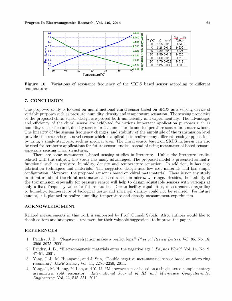
To realize this, the sensor layer thickness is fixed to 0.76 mm, and sensor layer is assumed to be filledwith marrowbone in different temperatures. In this sensing application, marrowbone’s electromagneticproperties such as dielectric constant and loss tangent values are taken from [33] at the frequencyof 10 GHz between 30◦C–90◦C. Marrowbone’s complex relative permittivity changes according to itstemperature. When the relative permittivity changes due to the temperature, it affects the relativepermittivity of the sensor layer according to εi = ε′r − jε′′r . For marrowbone, dielectric constant andloss tangent values are obtained from Hippel’s method around 9.5 GHz [34, 35].
ε′ =k2 + β2 − α2
β20
tan δ =2αβ
k2 + β2 − α2(4)
γ = α + jβ, k =2πλc
and β0 =2πλ
(5)
The propagation constant is evaluated from the equation of the hyperbolic tangent instead ofordinary tangent. All the other quantities are the same as for the “twice-minimum” method mentionedabove [34]. SRDS based chiral sensor simulation is completed according to the complex dielectricconstant data given in the inset of Fig. 10. These data are used to observe sensing of the SRDS basedchiral sensor with respect to the change of the dielectric constant, in other words, temperature changes.After simulation, resonance frequency/permittivity of marrowbone versus tissue temperature changesis plotted in Fig. 10. When the temperature of the marrowbone tissue is increased from 30◦C to 90◦C,resonance frequency decreases from 9.54 GHz to 9.508 GHz. Resonance frequency of the SRDS basedchiral sensor with respect to the temperature is also piecewise linear curve. The slope of the curve isnearly 1 MHz per temperature step, and it has observable frequency resolution for all types of networkanalyzer. The plot can be analyzed separately for two exact linear parts in order to obtain accurateslope of the relationship. The first linear part has a slope of 65◦ for unit temperature over the range of30–50◦C, and the second linear part has a slope of 40◦ for unit temperature over the range of 50–90◦C.When we look at the overall slopes of dielectric constant and resonance frequency, they are found as51◦ and 55◦.
Progress In Electromagnetics Research, Vol. 149, 2014 65
Figure 10. Variations of resonance frequency of the SRDS based sensor according to differenttemperatures.
7. CONCLUSION
The proposed study is focused on multifunctional chiral sensor based on SRDS as a sensing device ofvariable purposes such as pressure, humidity, density and temperature sensation. The sensing propertiesof the proposed chiral sensor design are proved both numerically and experimentally. The advantagesand efficiency of the chiral sensor are exhibited for various important application purposes such ashumidity sensor for sand, density sensor for calcium chloride and temperature sensor for a marrowbone.The linearity of the sensing frequency changes, and stability of the amplitude of the transmission levelprovides the researchers a novel sensor which is applicable to realize many different sensing applicationsby using a single structure, such as medical area. The chiral sensor based on SRDS inclusion can alsobe used for terahertz applications for future sensor studies instead of using metamaterial based sensors,especially sensing chiral structures.
There are some metamaterial-based sensing studies in literature. Unlike the literature studiesrelated with this subject, this study has many advantages. The proposed model is presented as multi-functional such as pressure, humidity, density and temperature sensation. In addition, it has easyfabrication techniques and materials. The suggested design uses low cost materials and has simpleconfiguration. Moreover, the proposed sensor is based on chiral metamaterial. There is not any studyin literature about the chiral metamaterial based sensor in microwave range. Besides, the stability ofthe transmission especially for pressure sensor will help to design adjustable sensors with varicaps atonly a fixed frequency value for future studies. Due to facility capabilities, measurements regardingto humidity, temperature of biological tissue and silica gel density could not be realized. For futurestudies, it is planned to realize humidity, temperature and density measurement experiments.
ACKNOWLEDGMENT
Related measurements in this work is supported by Prof. Cumali Sabah. Also, authors would like tothank editors and anonymous reviewers for their valuable suggestions to improve the paper.
REFERENCES
1. Pendry, J. B., “Negative refraction makes a perfect lens,” Physical Review Letters, Vol. 85, No. 18,3966–3975, 2000.
2. Pendry, J. B., “Electromagnetic materials enter the negative age,” Physics World, Vol. 14, No. 9,47–51, 2001.
3. Yang, J. J., M. Huangand, and J. Sun, “Double negative metamaterial sensor based on micro ringresonator,” IEEE Sensor, Vol. 11, 2254–2259, 2011.
4. Yang, J., M. Huang, Y. Lan, and Y. Li, “Microwave sensor based on a single stereo-complementaryasymmetric split resonator,” International Journal of RF and Microwave Computer-aidedEngineering, Vol. 22, 545–551, 2012.

66 Karaaslan and Bakir
5. Schueler, M., C. Mandel, M. Puentesand, and R. Jakoby, “Metamaterial inspired microwavesensors,” IEEE Microwave Magazine, Vol. 13, 57–68, 2012.
6. Melik, R., E. Unal, N. K. Perkgoz, B. Santoni, D. Kamstock, C. Puttlitzand, and H. V. Demir,“Nested metamaterials for wireless strain sensing,” IEEE Journal of Selected Topics in QuantumElectronics, Vol. 16, 450–458, 2010.
7. Cheng, Y., Y. Nie, Z. Cheng, and R. Z. Gong, “Dual-band circular polarizer and linear polarizationtransformer based on twisted split-ring structure asymmetric chiral metamaterial,” Progress InElectromagnetics Research, Vol. 145, 263–272, 2014.
8. Cheng, Y., Y. Nie, L. Wu, and R. Z. Gong, “Giant circular dichroism and negative refractiveindex of chiral metamaterial based on split-ring resonators,” Progress In Electromagnetics Research,Vol. 138, 263–272, 2013.
9. Sonsilphong, A. and N. Wongkasem, “Three-dimensional artificial double helices with high negativerefractive index,” Journal of Optics, Vol. 14, 105103, 2012.
10. Wongkasem, N., C. Kamtongdee, A. Akyurtlu, and K. Marx, “Artificial multiple helices:Polarization and EM properties,” Journal of Optics, Vol. 12, 075102, 2010.
11. Dincer, F., C. Sabah, M. Karaaslan, M. Bakir, and U. Erdiven, “Asymmetric transmission oflinearly polarized waves and dynamically wave rotation using chiral metamaterial,” Progress InElectromagnetics Research, Vol. 140, 227–239, 2013.
12. Sabah, C., H. T. Tastan, F. Dincer, K. Delihacioglu, M. Karaaslan, and E. Unal, “Transmissiontunneling through the multilayer double-negative and double-positive slabs,” Progress InElectromagnetics Research, Vol. 138, 293–306, 2013.
13. Ekmekci, E., R. D. Averitt, and G. T. Sayan, “Effects of substrate parameters on the resonancefrequency of double-sided SRR structures under two different excitations,” PIERS Proceedings,538–540, Cambridge, USA, Jul. 5–8, 2010.
14. Kriegler, C., “Bianisotropic photonic metamaterials,” IEEE Journal of Selectedtopics in QuantumElectronics, 1–15, 2010.
15. Wang, B., “Chiral metamaterials: Simulations and experiments,” Journal of Optics A, Pure andApplied Optics, Vol. 11, No. 11, 114003–114013, 2009.
16. Tretyakov, S., A. Sihvolaand, and L. Jylha, “Backward-wave regime and negative refraction inchiral composites,” Photonics and Nanostructures Fundamentals and Applications, Vol. 3, Nos. 2–3, 107–115, 2005.
17. Chen, T., S. Liand, and H. Suun, “Metamaterials application in sensing,” Sensors, Vol. 12, 2742–2765, 2012.
18. Soukoulis, C. M., S. Lindenand, and M. Wegener, “Negative refractive index at opticalwavelengths,” Science, Vol. 315, No. 5808, 47–49, 2007.
19. Aydin, K., I. Bulu, K. Guven, M. Kafesaki, C. M. Soukoulis, and E. Ozbay, “Investigation ofmagnetic resonances for different split-ring resonator parameters and designs,” New J. Phys., Vol. 7,168–182, 2005.
20. Ekmekci, E. and G. T. Sayan, “Multi-functional metamaterial sensor based on a broad-side coupledSRR topology with a multi-layer substrate,” Applied Physics A: Materials Science & Processing,Vol. 110, No. 1, 189–197, 2013.
21. Hendry, E., T. Carpy, J. Johnston, M. Popland, R. Mikhaylovskiy, A. J. Lapthorn, S. M. Kelly,L. D. Barron, N. Gadegaard, and M. Kadodwala, “Ultrasensitive detection and characterization ofbiomolecules using superchiral fields,” Nature Nanoletters, Vol. 5, 783–787, 2010.
22. Meng, F., Q. Wu, D. Erni, K. Wu, and J. C. Lee, “Polarization-independent metamaterial analog ofelectromagnetically induced transparency for a refractive-index-based sensor,” IEEE Transactionson Microwave Theory and Techniques, Vol. 60, No. 10, 3013–3022, 2012.
23. Willets, K. A. and R. P. van Duyne, “Localised surface plasmon resonance spectroscopy andsensing,” Ann. Rev. Phys. Chem., Vol. 58, 267–297, 2007.
24. Anker, J. N., W. Paige, O. Lyandres, C. Shah, J. Zhao, and R. V. Duyne, “Bio sensing withplasmonic nanosensors,” Nature Materials, Vol. 7, 442–453, Jun. 2008.
Progress In Electromagnetics Research, Vol. 149, 2014 67
25. Link, S. and M. A. El Sayed, “Spectral properties and relaxation dynamics of surface plasmonelectronic oscillations in gold and silver nanodots and nanorods,” J. Phys. Chem. B., Vol. 103,8410–8426, 1999.
26. Haes, A. J. and R. P. Duyne, “A nanoscale optical biosensor: Sensitivity and selectivity ofan approach based on the localised surface plasmon resonance spectroscopy of triangular silvernanoparticles,” J. Am. Chem. Soc., Vol. 124, 10596–10604, 2002.
27. Jung, L. S., C. T. Campell, T. M. Chinowsky, M. N. Mar, and S. S. Yee, “Quantitativeinterpretation of the response of surface plasmon resonance sensors to adsorbed film,” Langmuir,Vol. 14, 5636–5648, 1998.
28. Barbillon, G., “Plasmonic nanostructures prepared by soft UV nanoimprint lithography and theirapplication in biological sensing,” Micromachines, Vol. 3, 21–27, 2012.
29. Withayachumnankula, W., K. Jaruwongrungseeb, A. Tuantranontc, C. Fumeauxa, and D. Abbotta,“Metamaterial-based microfluidic sensor for dielectric characterization,” Sensors and Actuators A:Physical, Vol. 189, 233–237, 2013.
30. Vishvakarma, R. B. and C. S. Raid, “Measurement of complex dielectric constant of sand and dustparticles as a function of moisture content,” European Microwave Conference, Vol. 23, 568–570,1993.
31. Zheng, Y., G. Meyer, M. Lanagan, A. Dinesh, and C. Jiping, “A study of watersorption effects onthe microwave dielectric properties,” Materials Letters, Vol. 95, 157–159, 2013.
32. Yang, J., M. Huang, H. Tang, J. Zeng, and L. Dong, “Metamaterial sensors,” International Journalof Antennas and Propagation, Vol. 2013, 637270, 2013.
33. Factorova, D., “Temperature dependence of biological tissues complex permittivity at microwavefrequencies,” Advances in Electrical and Electronic Engineering, Vol. 7, 354–357, 2008.
34. Baker, J., E. Vanzura, and W. Kissik, “Improved technique for determining complex permittivitywith the transmission/reflection method,” IEEE Transactions on Microwave Theory andTechniques, Vol. 38, 1096–1103, 1990.
35. Faktorova, D., “Microwave nondestructive testing of dielectric materials,” Advances in Electricaland Electronic Engineering, Vol. 5, 230–233, 2006.