chlorine valves and accessories - cramer decker · chlorine valves and accessories chlorine...
TRANSCRIPT

Chlorine Valves Chlorine Valves Chlorine Valves and Accessoriesand Accessoriesand Accessories
Chlorine Cylinder Chlorine Cylinder Chlorine Cylinder & Ton Container Valves& Ton Container Valves& Ton Container Valves
Standard Chlorine Institute Design & Alternate DesignStandard Chlorine Institute Design & Alternate DesignStandard Chlorine Institute Design & Alternate Design

2
ALTERNATE VALVE DESIGN vs. STANDARD CHLORINE INSTITUTE VALVE DESIGN FOR CHLORINE CYLINDER AND TON CONTAINER VALVES
2200 N. Main Street Washington, PA 15301
Ph. 888-508-2583 Fax 800-416-0678
www.sherwoodvalve.com
Standard Chlorine Institute Valve
3
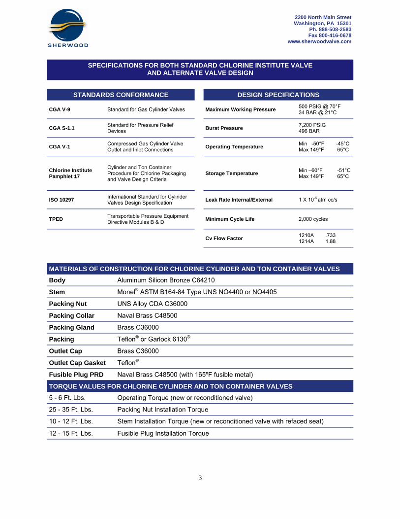
STANDARDS CONFORMANCE DESIGN SPECIFICATIONS
CGA V-9 Standard for Gas Cylinder Valves Maximum Working Pressure 500 PSIG @ 70°F 34 BAR @ 21°C
CGA S-1.1 Standard for Pressure Relief Devices
Burst Pressure 7,200 PSIG 496 BAR
CGA V-1 Compressed Gas Cylinder Valve Outlet and Inlet Connections
Operating Temperature Min -50°F -45°C Max 149°F 65°C
Chlorine Institute Pamphlet 17
Cylinder and Ton Container Procedure for Chlorine Packaging and Valve Design Criteria
Storage Temperature Min –60°F -51°C Max 149°F 65°C
ISO 10297 International Standard for Cylinder Valves Design Specification
Leak Rate Internal/External 1 X 10⁻⁶ atm cc/s
TPED Transportable Pressure Equipment Directive Modules B & D
Minimum Cycle Life 2,000 cycles
1210A .733 1214A 1.88
Cv Flow Factor
2200 North Main Street Washington, PA 15301
Ph. 888-508-2583 Fax 800-416-0678
www.sherwoodvalve.com
MATERIALS OF CONSTRUCTION FOR CHLORINE CYLINDER AND TON CONTAINER VALVES
Body Aluminum Silicon Bronze C64210
Stem Monel® ASTM B164-84 Type UNS NO4400 or NO4405
Packing Nut UNS Alloy CDA C36000
Packing Collar Naval Brass C48500
Packing Gland Brass C36000
Packing Teflon® or Garlock 6130®
Outlet Cap Brass C36000
Outlet Cap Gasket Teflon®
Fusible Plug PRD Naval Brass C48500 (with 165ºF fusible metal)
TORQUE VALUES FOR CHLORINE CYLINDER AND TON CONTAINER VALVES
5 - 6 Ft. Lbs. Operating Torque (new or reconditioned valve)
25 - 35 Ft. Lbs. Packing Nut Installation Torque
10 - 12 Ft. Lbs. Stem Installation Torque (new or reconditioned valve with refaced seat)
12 - 15 Ft. Lbs. Fusible Plug Installation Torque
SPECIFICATIONS FOR BOTH STANDARD CHLORINE INSTITUTE VALVE AND ALTERNATE VALVE DESIGN

4
STANDARD CHLORINE INSTITUTE VALVE DESIGN CHLORINE CYLINDER WRENCH OPERATED PACKED VALVES
INLET THREAD SIZE
CGA OUTLET*
PRESSURE RELIEF DEVICE
SHERWOOD P/N TEFLON® PACKING
SHERWOOD P/N GARLOCK® PACKING
¾ - 14NGT (CL)-1 660 / 820 CG-2 165°F Fuse-Metal 1210X1-B1 1210-B1
¾ - 14NGT (CL)-2 660 / 820 CG-2 165°F Fuse-Metal 1210X1-B2 1210-B2
¾ - 14NGT (CL)-3 660 / 820 CG-2 165°F Fuse-Metal 1210X1-B3 1210-B3
¾ - 14NGT (CL)-4 660 / 820 CG-2 165°F Fuse-Metal 1210X1-B4 1210-B4
STANDARD CHLORINE INSTITUTE VALVE DESIGN CHLORINE TON CONTAINER WRENCH OPERATED PACKED VALVES
INLET THREAD SIZE
CGA OUTLET*
PRESSURE RELIEF DEVICE
SHERWOOD P/N TEFLON® PACKING
SHERWOOD P/N GARLOCK® PACKING
¾ - 14NGT (CL)-1 660 / 820 None 1214X1-B1 1214A-CL1
¾ - 14NGT (CL)-2 660 / 820 None 1214X1-B2 1214-B2
¾ - 14NGT (CL)-3 660 / 820 None 1214X1-B3 1214-B3
¾ - 14NGT (CL)-4 660 / 820 None 1214X1-B4 1214-B4
2200 N. Main Street Washington, PA 15301
Ph. 888-508-2583 Fax 800-416-0678
www.sherwoodvalve.com
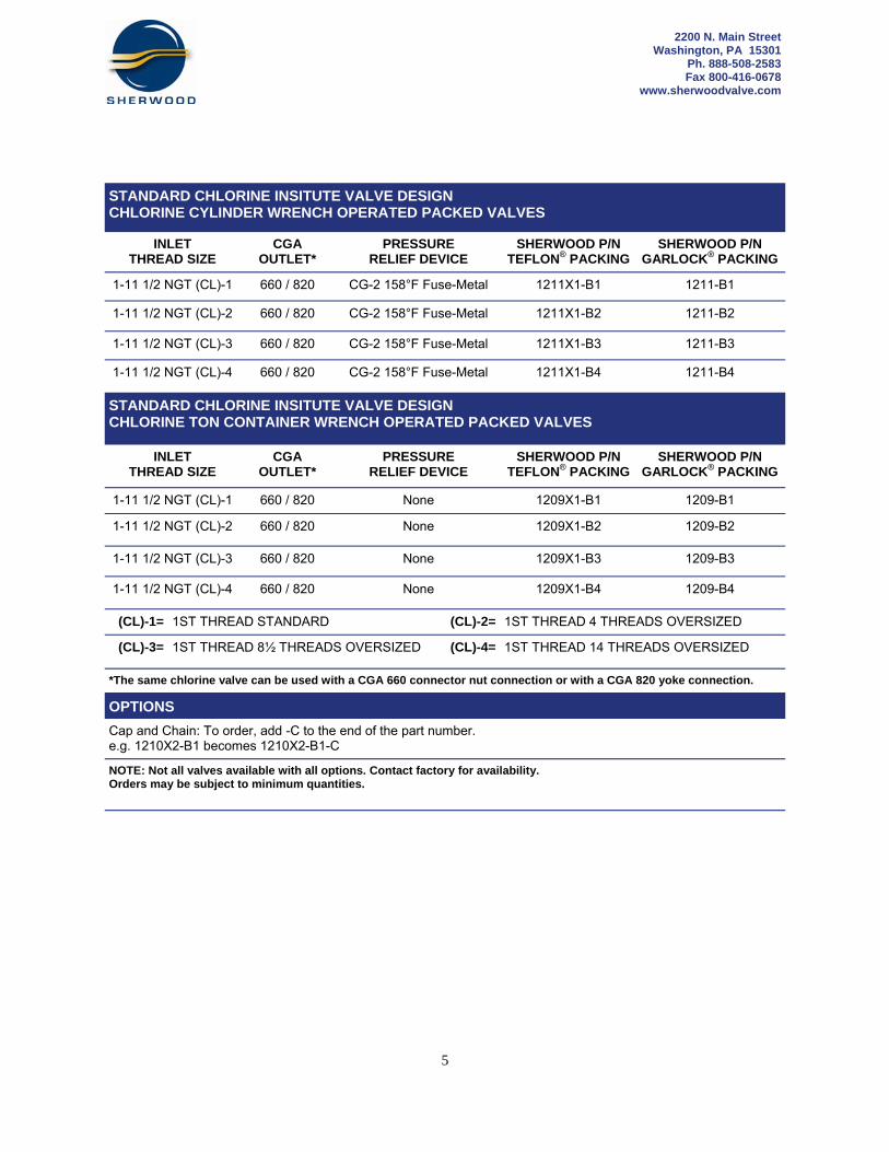
(CL)-1= 1ST THREAD STANDARD (CL)-2= 1ST THREAD 4 THREADS OVERSIZED
(CL)-3= 1ST THREAD 8½ THREADS OVERSIZED (CL)-4= 1ST THREAD 14 THREADS OVERSIZED
*The same chlorine valve can be used with a CGA 660 connector nut connection or with a CGA 820 yoke connection.
OPTIONS
Cap and Chain: To order, add -C to the end of the part number. e.g. 1210X2-B1 becomes 1210X2-B1-C
NOTE: Not all valves available with all options. Contact factory for availability. Orders may be subject to minimum quantities.
5
OPTIONS
Cap and Chain: To order, add -C to the end of the part number. e.g. 1210X2-B1 becomes 1210X2-B1-C
NOTE: Not all valves available with all options. Contact factory for availability. Orders may be subject to minimum quantities.
2200 N. Main Street Washington, PA 15301
Ph. 888-508-2583 Fax 800-416-0678
www.sherwoodvalve.com
(CL)-1= 1ST THREAD STANDARD (CL)-2= 1ST THREAD 4 THREADS OVERSIZED
(CL)-3= 1ST THREAD 8½ THREADS OVERSIZED (CL)-4= 1ST THREAD 14 THREADS OVERSIZED
*The same chlorine valve can be used with a CGA 660 connector nut connection or with a CGA 820 yoke connection.
STANDARD CHLORINE INSITUTE VALVE DESIGN CHLORINE CYLINDER WRENCH OPERATED PACKED VALVES
INLET THREAD SIZE
CGA OUTLET*
PRESSURE RELIEF DEVICE
SHERWOOD P/N TEFLON® PACKING
SHERWOOD P/N GARLOCK® PACKING
1-11 1/2 NGT (CL)-1 660 / 820 CG-2 158°F Fuse-Metal 1211X1-B1 1211-B1
1-11 1/2 NGT (CL)-2 660 / 820 CG-2 158°F Fuse-Metal 1211X1-B2 1211-B2
1-11 1/2 NGT (CL)-3 660 / 820 CG-2 158°F Fuse-Metal 1211X1-B3 1211-B3
1-11 1/2 NGT (CL)-4 660 / 820 CG-2 158°F Fuse-Metal 1211X1-B4 1211-B4
STANDARD CHLORINE INSITUTE VALVE DESIGN CHLORINE TON CONTAINER WRENCH OPERATED PACKED VALVES
INLET THREAD SIZE
CGA OUTLET*
PRESSURE RELIEF DEVICE
SHERWOOD P/N TEFLON® PACKING
SHERWOOD P/N GARLOCK® PACKING
1-11 1/2 NGT (CL)-1 660 / 820 None 1209X1-B1 1209-B1
1-11 1/2 NGT (CL)-2 660 / 820 None 1209X1-B2 1209-B2
1-11 1/2 NGT (CL)-3 660 / 820 None 1209X1-B3 1209-B3
1-11 1/2 NGT (CL)-4 660 / 820 None 1209X1-B4 1209-B4
6
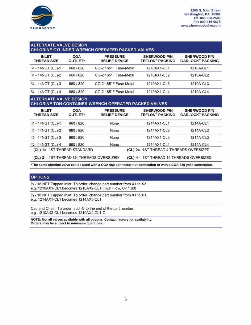
ALTERNATE VALVE DESIGN CHLORINE CYLINDER WRENCH OPERATED PACKED VALVES
INLET THREAD SIZE
CGA OUTLET*
PRESSURE RELIEF DEVICE
SHERWOOD P/N TEFLON® PACKING
SHERWOOD P/N GARLOCK® PACKING
¾ - 14NGT (CL)-1 660 / 820 CG-2 165°F Fuse-Metal 1210AX1-CL1 1210A-CL1
¾ - 14NGT (CL)-2 660 / 820 CG-2 165°F Fuse-Metal 1210AX1-CL2 1210A-CL2
¾ - 14NGT (CL)-3 660 / 820 CG-2 165°F Fuse-Metal 1210AX1-CL3 1210A-CL3
¾ - 14NGT (CL)-4 660 / 820 CG-2 165°F Fuse-Metal 1210AX1-CL4 1210A-CL4
ALTERNATE VALVE DESIGN CHLORINE TON CONTAINER WRENCH OPERATED PACKED VALVES
INLET THREAD SIZE
CGA OUTLET*
PRESSURE RELIEF DEVICE
SHERWOOD P/N TEFLON® PACKING
SHERWOOD P/N GARLOCK® PACKING
¾ - 14NGT (CL)-1 660 / 820 None 1214AX1-CL1 1214A-CL1
¾ - 14NGT (CL)-2 660 / 820 None 1214AX1-CL2 1214A-CL2
¾ - 14NGT (CL)-3 660 / 820 None 1214AX1-CL3 1214A-CL3
¾ - 14NGT (CL)-4 660 / 820 None 1214AX1-CL4 1214A-CL4
(CL)-1= 1ST THREAD STANDARD (CL)-2= 1ST THREAD 4 THREADS OVERSIZED
(CL)-3= 1ST THREAD 8½ THREADS OVERSIZED (CL)-4= 1ST THREAD 14 THREADS OVERSIZED
*The same chlorine valve can be used with a CGA 660 connector nut connection or with a CGA 820 yoke connection.
OPTIONS
⅜ - 18 NPT Tapped Inlet: To order, change part number from X1 to X2. e.g. 1210AX1-CL1 becomes 1210AX2-CL1 (High Flow, Cv 1.88)
Cap and Chain: To order, add -C to the end of the part number. e.g. 1210AX2-CL1 becomes 1210AX2-CL1-C
¼ - 18 NPT Tapped Inlet: To order, change part number from X1 to X3. e.g. 1214AX1-CL1 becomes 1214AX3-CL1
NOTE: Not all valves available with all options. Contact factory for availability. Orders may be subject to minimum quantities.
2200 N. Main Street Washington, PA 15301
Ph. 888-508-2583 Fax 800-416-0678
www.sherwoodvalve.com
7
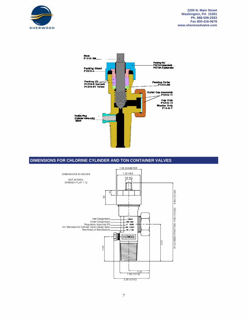
DIMENSIONS FOR CHLORINE CYLINDER AND TON CONTAINER VALVES
2200 N. Main Street Washington, PA 15301
Ph. 888-508-2583 Fax 800-416-0678
www.sherwoodvalve.com

8
REPAIR INSTRUCTIONS FOR CHLORINE CYLINDER AND TON CONTAINER VALVES
DISASSEMBLY OF VALVE A. Place the valve assembly into a vise or similar holding fixture. The holding fixture must securely grip the valve body on the wrench flats so no damage is done to the internal bores, external or internal threads, outlet, or fusible plug PRD. B. Chamber 1. Using a 1¼ socket or hex box wrench, remove the packing nut by turning it counter clockwise. 2. Using a ⅜ square socket or open end wrench, remove the stem from the valve chamber by turning it counter clockwise. The packing gland, the two packings, and the packing collar will be removed with the stem. 3. Remove the packing gland, the two packings, and the packing collar from the stem. C. Outlet 1. Remove the outlet cap from the valve assembly by turning it counter clockwise. D. Fusible Plug Pressure Relief Device (Cylinder Valves) 1. Using a 7/16 socket or hex box wrench, remove the fusible plug PRD by turning it counter clockwise. INSPECTION OF VALVE AND COMPONENTS A. Valve Body 1. Inspect the valve body for cracks. If cracks are suspected, scrap the valve body. Inspect the valve body cham ber bore for dirt, debris and damage. Blow out the valve body chamber using clean, dry compressed air or nitro gen to remove these contaminants. 2. Examine all internal and external threads for damage or deterioration due to wear or corrosion. Special atten tion should be given to the threads closest to the outlet since they are the most vulnerable to corrosive attack. 3. Examine the valve body seat for excessive wear or corrosion build up. Wear creating a ⅛ x 90° or greater bevel should be eliminated with the 1534 reseating tool (1210/1214) or 1534A reseating tool(1210A/1214A). The valve has reached its end of life and should be replaced when the tool can no longer remove this bevel. 4. Clean the internal threads for the fusible plug to remove all thread luting compound. 5. If the valve body is damaged or corroded, do not attempt to repair. Order a new valve assembly. B. Components 1. Scrap any component that is suspected of being cracked. Also, replace components damaged, worn or cor roded to the point where safe operation, valve performance or leak integrity may be compromised. Special atten tion should be given to wear grooves in the nose of the stem. Stems with grooves 1/64 or greater in depth should be replaced. 2. Special attention should be given to the fuse plug for signs of leakage an extrusion of the fusible metal greater than 1/64 which may adversely affect use of the emergency kit tool used to temporarily seal fusible metal leaks. 3. It is recommended that both of the packings be replaced before the valve is reassembled.
2200 N. Main Street Washington, PA 15301
Ph. 888-508-2583 Fax 800-416-0678
www.sherwoodvalve.com

9
ASSEMBLY OF VALVE NOTE: All parts must be clean, free of oil, chips and other contaminants before beginning assembly. A properly calibrated torque wrench must be used. Over tightening will damage components and the valve body. Under tightening may result in leaks. Reassembly of a used valve should not begin until all the components of that valve have been examined to determine their combined effects on valve performance and operation. A. Chamber 1. Insert the stem into the valve chamber and turning it clockwise, engage it one full thread. Engaging the stem more than one full thread may make installation of parts difficult. 2. Place the packing collar, flat side down, onto the stem. 3. Install two packings with the flat sides facing each other, and place them onto the stem. 4. Place the packing gland with the beveled end down onto the stem. 5. Tighten the stem using a ⅜ square socket and a torque wrench to 10-12 ft. lbs. to coin the seat in the body. 6. Press down on the packing gland until the two packings are completely below the top of the body. 7. Install the packing nut over the stem. Making sure the threads are properly engaged, tighten the packing nut to 25-30 ft. lbs. using a 1¼ socket and torque wrench. B. Outlet 1. Install the outlet cap onto the valve assembly outlet, turning clockwise until hand tight. C. Fusible Plug PRD (Cylinder Valve) 1. Apply a chlorine compatible thread luting compound onto the bottom threads of the fusible plug PRD. 2. Thread the fusible plug PRD, finger tight, making sure at least one thread is engaged in the body. 3. Using a 7/16 socket and a proper torque wrench, tighten the fusible plug to 12-15 ft. lbs. or 1½ - 2 turns. TESTING OF ASSEMBLED VALVE NOTE: Only leak detection solutions compatible with chlorine should be used. Thus, only commercial or household detergents should be used that DO NOT contain ammonia, phosphates or other chemicals which are harmful to copper alloys and can initiate stress corrosion cracking of these alloys. A. Test each reassembled valve by installing the valve securely in a suitable test fixture and pressurizing the valve
with air, nitrogen or carbon dioxide to 500 psig. B. With the outlet plugged or capped, open the valve assembly slowly and check for leaks through the valve body,
past the stem and all threaded connections using a leak detection solution. C. Close the valve assembly and remove the outlet cap assembly or plug. Pressurize the valve to 500 psig and
check for seat leakage through the outlet. C. If any leakage is detected, in the open or closed position, make necessary repairs and retest the valve before
returning to service. NOTE: Periodic retightening of the packing nut to 25-30 ft lbs. may be required to maintain a leak tight packing nut and stem seal. However, tightening more than is necessary or applying excessive torques will prematurely wear the packings and may damage the packing nut and the valve body threads.
REPAIR INSTRUCTIONS FOR CHLORINE CYLINDER AND TON CONTAINER VALVES
2200 N. Main Street Washington, PA 15301
Ph. 888-508-2583 Fax 800-416-0678
www.sherwoodvalve.com
10
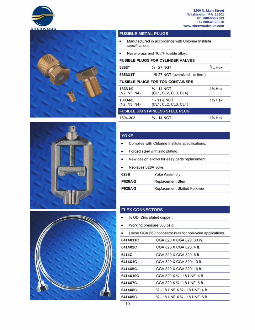
FUSIBLE METAL PLUGS
Manufactured in accordance with Chlorine Institute specifications.
Naval brass and 165°F fusible alloy.
FUSIBLE PLUGS FOR CYLINDER VALVES
5853T ⅛ - 27 NGT 7/16 Hex
FUSIBLE PLUGS FOR TON CONTAINERS
1333-N1 (N2, N3, N4)
¾ - 14 NGT (CL1, CL2, CL3, CL4)
1¼ Hex
1303-N1 (N2, N3, N4)
1 - 11½ NGT (CL1, CL2, CL3, CL4)
1¼ Hex
1304-303 ¾ - 14 NGT 1¼ Hex
FUSIBLE 303 STAINLESS STEEL PLUG
5853X1T 1/8-27 NGT (oversized 1st thrd.)
YOKE
Complies with Chlorine Institute specifications.
Forged steel with zinc plating.
New design allows for easy parts replacement.
628B Yoke Assembly
P628A-2 Replacement Stem
P628A-3 Replacement Slotted Follower
Replaces 628A yoke.
FLEX CONNECTORS
⅜ OD, Zinc plated copper.
Working pressure 500 psig.
6414X11C CGA 820 X CGA 820; 30 in.
6414X2C CGA 820 X CGA 820; 4 ft.
6414C CGA 820 X CGA 820; 6 ft.
6414X1C CGA 820 X CGA 820; 10 ft.
6414X5C CGA 820 X CGA 820; 16 ft.
6414X10C CGA 820 X ⅝ - 18 UNF; 4 ft.
6414X7C CGA 820 X ⅝ - 18 UNF; 6 ft.
6414X8C ⅝ - 18 UNF X ⅝ - 18 UNF; 4 ft.
6414X9C ⅝ - 18 UNF X ⅝ - 18 UNF; 6 ft.
Loose CGA 660 connector nuts for non-yoke applications.
2200 N. Main Street Washington, PA 15301
Ph. 888-508-2583 Fax 800-416-0678
www.sherwoodvalve.com

11
WRENCHES
Designed for use with 1210/1214 and 1210A/1214A chlorine valves and yokes.
Forged steel construction.
1¼ open end; ⅜ stem square.
635 Straight Shaft
635X3 Twisted Shaft
1534 / 1534A RESEATING TOOL
Increase the life of the valve with easy to use, manually operated, reseating tool. 1534 For use with 1210 and 1214. 1534A For use with 1210A and 1214A.
5928 CHARGING VALVE
The 5928 valve is a modification of Sherwood’s ton container valve. A chlorine adapter is soldered on the outlet to permit yoke attachment to all standard chlorine cylinder valves. A standard CGA 660 outlet connection has been machined where the cylinder inlet normally is to permit connection to the permanent chlorine charging or discharge line.
HIGH FLOW YOKE ADAPTERS
5888-6 ⅜ SAE Flare
5888-6S ⅜ ODS
5888-8 ½ SAE Flare
5888-D ½ - 14 NPT (male)
5888-E 1.030 - 14 NGO (male)
GASKETS FOR YOKE ADAPTERS
P10-CLAL Lead Outlet Gasket (.937 OD)
P10-CLBL Lead Outlet Gasket (.531 OD)
8
6S 6
D
E
2200 N. Main Street Washington, PA 15301
Ph. 888-508-2583 Fax 800-416-0678
www.sherwoodvalve.com
12
For more information / to place an order: Sherwood Distribution Breard-Gardner, Inc., John H Carter Co Baton Rouge, LA Phone: 225-272-4420 Fax: 225-273-4492 Sidener Environmental St. Louis, MO Phone: 800-528-2887 Fax: 314-991-3527 Cramer-Decker Industries Santa Ana, CA Phone: 800-752-4579 Phone: 714-566-3850 Fax: 714-566-3869 Evergreen Midwest Inc. Mentor, OH Phone: 800-659-3358 Fax: 440-255-6434 Ray Murray Inc. Sales & Customer Service: 1-800-628-5044 Lee, MA 01238 Phone: 413-243-2164 Fax: 413-243-4211 Peter Skop Industries, Inc. Norcross, GA 30071 Phone: 888-241-9880 Fax : 800-849-4774
International Distributors: Chemtech International Media, PA Phone: 610-566-7177 Fax: 610-566-9198 Export Consultant Service, Inc. Coraopolis, PA Phone: 412-264-7877 Fax: 412-264-4543 Sherwood Contact: Sherwood USA Ph. 888-508-2583 Fax 800-416-0678 [email protected] Sherwood Latin America Ph. (57) 310 407 4654 Sherwood Europe Ph. (49) 48 41 9 85-0 Fax (49) 48 41 9 85-1 Sherwood Asia Ph. (60 3) 5191-3003 Fax (60 3) 5191-1472 Sherwood Australia Ph (61 2) 60 402533 Fax (61 2) 60 402510
SWDCHLORINE_3_2010 ©Copyright 2010 SHERWOOD VALVE LLC, ALL RIGHTS RESERVED
www.sherwoodvalve.com