cho-seal & cho-sil conductive elastomers...cho-seal 1298 corrosion-resistant emi shielding...
TRANSCRIPT
30US Headquarters TEL +(1) 781-935-4850 FAX +(1) 781-933-4318 • www.chomerics.com
Europe TEL +(44) 1628 404000 FAX +(44) 1628 404090Asia Pacific TEL +(852) 2 428 8008 FAX +(852) 2 423 8253
South America TEL +(55) 11 3917 1099 FAX +(55) 11 3917 0817
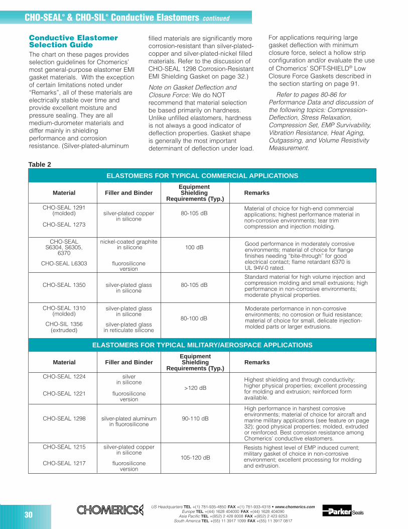
Good performance in moderately corrosiveenvironments; material of choice for flangefinishes needing “bite-through” for goodelectrical contact; flame retardant 6370 is UL 94V-0 rated.
CHO-SEAL® & CHO-SIL® Conductive Elastomers continued
Conductive ElastomerSelection GuideThe chart on these pages providesselection guidelines for Chomerics’most general-purpose elastomer EMIgasket materials. With the exceptionof certain limitations noted under“Remarks”, all of these materials areelectrically stable over time andprovide excellent moisture andpressure sealing. They are allmedium-durometer materials anddiffer mainly in shieldingperformance and corrosionresistance. (Silver-plated-aluminum
ELASTOMERS FOR TYPICAL COMMERCIAL APPLICATIONS
filled materials are significantly morecorrosion-resistant than silver-plated-copper and silver-plated-nickel filledmaterials. Refer to the discussion ofCHO-SEAL 1298 Corrosion-ResistantEMI Shielding Gasket on page 32.)
Note on Gasket Deflection andClosure Force: We do NOTrecommend that material selectionbe based primarily on hardness.Unlike unfilled elastomers, hardnessis not always a good indicator ofdeflection properties. Gasket shapeis generally the most importantdeterminant of deflection under load.
For applications requiring largegasket deflection with minimumclosure force, select a hollow stripconfiguration and/or evaluate the useof Chomerics’ SOFT-SHIELD® LowClosure Force Gaskets described inthe section starting on page 91.
Refer to pages 80-86 forPerformance Data and discussion ofthe following topics: Compression-Deflection, Stress Relaxation,Compression Set, EMP Survivability,Vibration Resistance, Heat Aging,Outgassing, and Volume ResistivityMeasurement.
Material of choice for high-end commercialapplications; highest performance material innon-corrosive environments; tear trimcompression and injection molding.
Standard material for high volume injection andcompression molding and small extrusions; highperformance in non-corrosive environments;moderate physical properties.
Moderate performance in non-corrosiveenvironments; no corrosion or fluid resistance;material of choice for small, delicate injection-molded parts or larger extrusions.
ELASTOMERS FOR TYPICAL MILITARY/AEROSPACE APPLICATIONS
Highest shielding and through conductivity;higher physical properties; excellent processingfor molding and extrusion; reinforced formavailable.
High performance in harshest corrosiveenvironments; material of choice for aircraft andmarine military applications (see feature on page32); good physical properties; molded, extruded or reinforced. Best corrosion resistance amongChomerics’ conductive elastomers.
Resists highest level of EMP induced current;military gasket of choice in non-corrosiveenvironment; excellent processing for moldingand extrusion.
EquipmentMaterial Filler and Binder Shielding Remarks
Requirements (Typ.)CHO-SEAL 1224 silver
in silicone>120 dB
CHO-SEAL 1221 fluorosiliconeversion
CHO-SEAL 1298 silver-plated aluminum 90-110 dBin fluorosilicone
CHO-SEAL 1215 silver-plated copperin silicone
105-120 dBCHO-SEAL 1217 fluorosilicone
version
Table 2
EquipmentMaterial Filler and Binder Shielding Remarks
Requirements (Typ.)CHO-SEAL 1291
(molded) silver-plated copper 80-105 dBin silicone
CHO-SEAL 1273
CHO-SEAL nickel-coated graphiteS6304, S6305, in silicone 100 dB
6370
CHO-SEAL L6303 fluorosiliconeversion
CHO-SEAL 1350 silver-plated glass 80-105 dBin silicone
CHO-SEAL 1310(molded)
silver-plated glassin silicone
CHO-SIL 1356 silver-plated glass(extruded) in reticulate silicone
80-100 dB

US Headquarters TEL +(1) 781-935-4850 FAX +(1) 781-933-4318 • www.chomerics.comEurope TEL +(44) 1628 404000 FAX +(44) 1628 404090
Asia Pacific TEL +(852) 2 428 8008 FAX +(852) 2 423 8253South America TEL +(55) 11 3917 1099 FAX +(55) 11 3917 0817
31
EquipmentMaterial Filler and Binder Shielding Remarks
Requirements (Typ.)
CHO-SEAL 1285 silver-plated aluminumin silicone
90-110 dBCHO-SEAL 1287 fluorosilicone
version
CHO-SEAL 1278 silver-plated nickel >100 dBin silicone
CHO-SEAL nickel-coated graphiteS6304, S6305, in silicone
6370 >100 dB
CHO-SEAL L6303 fluorosiliconeversion
ELASTOMERS FOR TYPICAL MILITARY/AEROSPACE APPLICATIONS continued
Military gasket of choice for corrosiveenvironments; lightweight, 200°C max. usetemperature; good EMP resistance; molded,extruded and reinforced.
High performance in non-corrosiveenvironments; molded parts only; no fluidresistance.
Good performance in moderately corrosiveenvironments; material of choice for flangefinishes needing “bite-through” for goodelectrical contact; flame retardant 6370 is UL94V-0 rated.
EquipmentMaterial Filler and Binder Shielding Remarks
Requirements (Typ.)
CHO-SEAL 1501 silver in 80-100 dBsilicone foam
CHO-SIL 1401 silver in 80-100 dBreticulate silicone
CHO-SEAL 1239silver-plated copper
110 dBin silicone withexpanded copper
reinforcement
CHO-SEAL 1212 silver-plated copper 120 dBin silicone
CHO-SEAL E6434 95 dB(molded) silver-plated nickel
in EPDMCHO-SEAL E6434E 90 dB(extruded)
CHO-SEAL E6306 nickel-coated graphite >90 dBin EPDM
CHO-SEAL V6433 silver-plated nickel 100 dBin fluorocarbon
CHO-SIL 1485 silver-plated aluminum 50-100 dBin reticulate silicone
CHO-SEAL S6600 carbon 30-80 dBand S6602 in silicone
SPECIALTY ELASTOMERS
Soft (30 Shore A) for low closure force wheregasket shape cannot be exploited; low tearstrength; no corrosion resistance or fluidresistance; sheet stock only.
High performance for non-corrosive environments;soft (45 Shore A) for low closure force wheregasket shape cannot be exploited; low tearstrength; no fluid resistance.
Material for waveguide choke, cover, and flangeEMI shielding and pressure sealing; maximumheat transfer and minimum outgassing; hard (80Shore A), high-strength material; available withraised lip around iris opening for high power/high pressure applications.
High strength, hard (80 Shore A) material forwaveguide, choke, cover, and flanges withgrooves for EMI and pressure sealing.
Material of choice for high shielding where NBCfluid resistance is needed; high performance incorrosive environments.
Good performance in moderately corrosiveenvironments; excellent NBC fluid resistance;good physical properties.
Material of choice for extensive fluid resistance;no corrosion resistance.
Moderate corrosion resistance formilitary applications.
Low-end shielding or ESD protection; high tensilestrength; no corrosion or fluid resistance.
Table 2 continued

32US Headquarters TEL +(1) 781-935-4850 FAX +(1) 781-933-4318 • www.chomerics.com
Europe TEL +(44) 1628 404000 FAX +(44) 1628 404090Asia Pacific TEL +(852) 2 428 8008 FAX +(852) 2 423 8253
South America TEL +(55) 11 3917 1099 FAX +(55) 11 3917 0817
CHO-SEAL1298Corrosion-ResistantEMI Shielding Gasket
CHO-SEAL 1298 elastomerincorporates unique particle platingand elastomer technology forincreased corrosion resistance.When used in conjunction with theCHO-SHIELD 2000 series of corrosion-resistant conductive coatings onaluminum flanges, a corrosion-proofEMI flange system is obtained.CHO-SEAL 1298 gasket material isbased on a silver-plated-aluminumfiller dispersed in a fluorosilicone
binder, with corrosion inhibitingadditives that contain no chromates.It offers shielding effectiveness of100 dB at 500 MHz and meets allrequirements of MIL-G-83528 Type D(initial and aged). CHO-SEAL 1298gasket material also has excellentresistance to fluids and fuelscommonly used in aviation andindustrial applications.
Corrosion Resistance TestingChomerics has completed
extensive corrosion resistance testingon CHO-SEAL 1298 gasket material
using a gravimetric weight lossprocedure. A copy of the testmethod (CHO-TM 100) is availableon request from Chomerics. Testfixtures and elastomer samples arealso available. Contact Chomerics’Applications Engineering Departmentfor further information.
Lightning Strike ResistanceThe survivability of any system to
lightning strike is dependent onspecific flange design. Lightningstrike testing of CHO-SEAL 1298gasket material has demonstrated
a Copies of CEPS-0002 and CHO-TM-TP08 are available from Chomericsb Compression set is expressed as a percentage of deflection per ASTM D395 Method B., at 25% deflection. To determine percent recovery, subtract 1/4 of stated
compression set value from 100%. For example, in the case of 30% compression set, recovery is 92.5%.c Where two values are shown: First represents max. operating temp. for conformance to MIL-G-83528 (which requires Group A life testing at 1.25 times max. operating
temp.) Second value represents practical limit for exposure up to 1000 hours (compressed between flanges 7-10%). Single value conforms to both definitions.d Extruded version of 1215 was formerly designated 1250; extruded version of 1401 was formerly designated 1405.e Second value applies to extruded forms only.f CHO-SIL 1401 degrades electrically after simulated EMP current levels < 0.9 kA per in.
dB, m
in.
CONDUCTIVE ELASTOMER SPECIFICATIONS (grouped by filler)
Method (1)CHO-TM-TP08a
Method (2)MIL-G-83528
Para 4.6.12 (Q)
Method (2) Method (2) Method (1)Method (2)Method (2)
Table 3
Method (2)
Note: It may not be inferred that the same level of shielding effectiveness provided by a gasket material tested in the fixture per MIL-G-83528 Para. 4.6.12 would be provided in an actualequipment flange, since many mechanical factors of the flange design (tolerances, stiffness, fastener location, and size, etc.) could lower or enhance shielding effectiveness. This procedureprovides data applicable only to the test fixture design of MIL-G-83528, but which is useful for making comparisons between different gasket materials.
CHO-SEAL® & CHO-SIL® Conductive Elastomers continued
Method (2) Method (2) Method (2)
■ Not available in extruded form.NA Not Applicable (Q) Qualification(C) QC Conformance
Test Procedure CHO-SEAL CHO-SEAL CHO-SIL CHO-SEAL CHO-SEAL CHO-SEAL CHO-SEAL CHO-SEAL CHO-SEAL(Type of Test) 1221 1224 1401d 1501■ 1212■ 1215d 1217 1239 ■ 1273
Conductive Filler Ag Ag Ag Ag Ag/Cu Ag/Cu Ag/Cu Ag/Cu Ag/Cu
Elastomer Binder Fluoro- Silicone Silicone Silicone Silicone Silicone Fluoro- Silicone Siliconesilicone silicone
Type (Ref. MIL-G-83528) Type F Type E — — Type K Type A Type C Type G —
Volume Resistivity, ohm-cm, max., CEPS-0002a — — — — — — — — 0.004as supplied (without pressure- MIL-G-83528 0.002 0.002 0.010 0.03 0.005 0.004 0.010 0.007 —sensitive adhesive)Para. 4.6.11Hardness (Shore A ) ASTM D2240 (Q/C) 75 ±5 65 ±5 45 ±5 35 ±7 80 ±5 65 ±5 75 ±5 80 ±5 65 ±8
Specific Gravity (±0.25) ASTM D792 (Q/C) 4.0 3.5 ±0.45 1.6 2.7 (typ.) 3.5 3.5 ±0.45 4.1/3.8e 4.75 ±0.75 3.7
Tensile Strength, psi (MPa), min. ASTM D412 (Q/C) 250 (1.72) 300 (2.07) 200 (1.38) 80 (0.55) 400 (2.76) 200 (1.38) 180 (1.24) 600 (4.14) 175 (1.21)
Elongation, % min. or % min./max. ASTM D412 (Q/C) 100/300 200/500 75 NA 100/300 100/300 100/300 20/NA 75
Tear Strength, lb/in. (kN/m), min. ASTM D624 (Q) 40 (7.00) 50 (8.75) 20 (3.50) 20 (3.50) 40 (7.00) 40/25e 35 (6.13) 70 (12.25) —
Compression Set, 70 hrs @ 100°C, ASTM D395 60 45 35 80 35 32 35 NA 32% max.b Method B (Q)
LowTemperature FlexTR10,°C,min. ASTM D1329 (Q) –65 -65 –55 NA –45 –65 –55 NA –65
Maximum Continuous Use (Q) 160/200 160/200 160/200 160/200 125 125 125 125 125Temperature, °Cc
200 kHz (H Field) 70 70 60 60 70 70 70 70 —100 MHz (E Field) 120 120 100 100 120 120 120 110 100500 MHz (E Field) 120 120 100 100 120 120 120 110 100 2 GHz (Plane Wave) 120 120 90 90 120 120 115 110 10010 GHz (Plane Wave) 120 120 80 80 120 120 110 110 100
CEPS-0002a — — — — — — — — 0.01Heat Aging MIL-G-83528 0.010 0.010 0.015 NA 0.010 0.010 0.015 0.010 —Para. 4.6.15 (Q/C)
Vibration During MIL-G-83528 (Q) 0.010 0.010 0.015 NA 0.010 0.006 0.015 0.010 —Resistance After Para. 4.6.13 (Q) 0.002 0.002 0.01 0.03 0.005 0.004 0.010 0.007 —Post Tensile Set MIL-G-83528 0.010 0.010 0.02 NA 0.010 0.008 0.015 NA —Volume Resistivity Para. 4.6.9 (Q/C)
EMP Survivability, MIL-G-83528 >0.9 >0.9 note f >0.3 >0.9 >0.9 >0.9 >0.9 —kA per in. perimeter Para. 4.6.16 (Q)
Shie
ldin
gEf
fect
iven
ess
(see
Not
e be
low
)
ohm
-cm
, max
.
Elec
tric
al S
tabi
lity

US Headquarters TEL +(1) 781-935-4850 FAX +(1) 781-933-4318 • www.chomerics.comEurope TEL +(44) 1628 404000 FAX +(44) 1628 404090
Asia Pacific TEL +(852) 2 428 8008 FAX +(852) 2 423 8253South America TEL +(55) 11 3917 1099 FAX +(55) 11 3917 0817
33
Comparison ofcorrosion resultsobtained fromCHO-SEAL 1298conductiveelastomer (left)and pure silver-filled elastomer(right) mated withchromatedaluminum for 168hours of salt fogexposure.
survivability beyond 5 kA/in. Testdata is available on request.
Ordering InformationCHO-SEAL 1298 gaskets are
available in all standard formsincluding molded, die-cut andextruded. The material is alsoavailable reinforced with DupontDacron® fabric, woven wire meshand/or 3M Nextel® fabric. See page76 for more information.
For more information on corrosioncontrol, refer to the EMI ShieldingTheory and Design Guide, whichbegins on page 191.
Table 3 continued
Test Procedure CHO-SEAL CHO-SEAL CHO-SEAL CHO-SEAL CHO-SEAL CHO-SEAL CHO-SEAL CHO-SEAL CHO-SIL CHO-SEAL(Type of Test) 1291■ 1278■ V6433■ E6434■ E6434E• 1285 1287 1298 1485 1310■
Conductive Filler Ag/Cu Ag/Ni Ag/Ni Ag/Ni Ag/Ni Ag/Al Ag/Al Passivated Ag/Al Ag/GlassAg/Al
Elastomer Binder Silicone Silicone Fluorocarbon/ EPDM EPDM Silicone Fluoro- Fluoro- Silicone SiliconeFluorosilicone silicone silicone
Type (Ref. MIL-G-83528) — Type L — — — Type B Type D Type D — —
Volume Resistivity, ohm-cm, max., CEPS-0002a 0.004 — — — — — — — — 0.01as supplied (without pressure- MIL-G-83528 — 0.005 0.006 0.006 0.05 0.008 0.012 0.012 0.02 —sensitive adhesive) Para. 4.6.11Hardness (Shore A) ASTM D2240 (Q/C) 70 ±5 75 ±5 85 ±7 75 ±7 80 ±7 65 ±5 70 ±5 70 ±5 60 ±5 70 ±10
Specific Gravity (±0.25) ASTM D792 (Q/C) 3.45 4.0 4.8 3.9 3.8 1.9 2.0 2.0 1.7 1.8
Tensile Strength, psi (MPa), min. ASTM D412 (Q/C) 175 (1.21) 200 (1.38) 400 (2.76) 200 (1.38) 200 (1.38) 200 (1.38) 180 (1.24) 180 (1.24) 180 (1.24) 200 (1.38)
Elongation, % min. or % min./max. ASTM D412 (Q/C) 75 100/300 50 200 100 100/300 60/260 60/260 100 100
Tear Strength, lb/in. (kN/m), min. ASTM D624 (Q) — 30 (5.25) 70 (12.25) 75 (13.13) 70 (12.25) 30 (5.25) 35 (6.13) 35 (6.13) 30 (5.25)
Compression Set, 70 hrs @ 100°C, ASTM D395 32 32 45 40 40 32 30 30 30 35% max.b Method B (Q)
LowTemperature FlexTR10,°C,min. ASTM D1329 (Q) –45 –55 –25 –45 –45 –65 -55 –55 –40 –40
Maximum Continuous Use (Q) 125 125 200 100 100 160/200 160/200 160/200 85 160Temperature, °Cc
200 kHz (H Field) — 70 — — — 60 55 55 50 —100 MHz (E Field) 100 120 105 105 90 115 110 110 100 100500 MHz (E Field) 100 120 100 100 90 110 100 100 100 100 2 GHz (Plane Wave) 100 115 90 85 90 105 95 95 90 9010 GHz (Plane Wave) 100 110 90 85 90 100 90 90 80 80
CEPS-0002a 0.008 — — — — — — — — 0.01Heat Aging MIL-G-83528 — 0.010 0.008g 0.0125h 0.05h 0.010 0.015 0.015 0.06g —Para. 4.6.15 (Q/C)
Vibration During MIL-G-83528 (Q) — 0.010 NA NA NA 0.012 0.015 0.015 0.06 —Resistance After Para. 4.6.13 (Q) — 0.005 NA NA 0.05 0.008 0.012 0.012 0.02 —Post Tensile Set MIL-G-83528 — 0.010 — — NA 0.015 0.015 0.015 NA —Volume Resistivity Para. 4.6.9 (Q/C)
EMP Survivability, MIL-G-83528 — >0.9 NA NA — >0.9 >0.9 >0.9 >0.3 —kA per in. perimeter Para. 4.6.16 (Q)
CONDUCTIVE ELASTOMER SPECIFICATIONS (grouped by filler)
Shie
ldin
gEf
fect
iven
ess
(see
Not
e be
low
)El
ectr
ical
Sta
bilit
y
Method (1)CHO-TM-TP08a
Method (2)MIL-G-83528
Para 4.6.12 (Q)
Method (2) Method (1)Method (2)Method (2) Method (2) Method (2) Method (2) Method (2) Method (1)
Note: It may not be inferred that the same level of shielding effectiveness provided by a gasket material tested in the fixture per MIL-G-83528 Para. 4.6.12 would be provided in an actualequipment flange, since many mechanical factors of the flange design (tolerances, stiffness, fastener location, and size, etc.) could lower or enhance shielding effectiveness. This procedureprovides data applicable only to the test fixture design of MIL-G-83528, but which is useful for making comparisons between different gasket materials.
a Copies of CEPS-0002 and CHO-TM-TP08 are available from Chomericsb Compression set is expressed as a percentage of deflection per ASTM D395 Method B., at 25% deflection. To determine percent recovery, subtract 1/4 of stated
compression set value from 100%. For example, in the case of 30% compression set, recovery is 92.5%.c Where two values are shown: First represents max. operating temp. for conformance to MIL-G-83528 (which requires Group A life testing at 1.25 times max. operating
temp.) Second value represents practical limit for exposure up to 1000 hours (compressed between flanges 7-10%). Single value conforms to both definitions.g Heat aging condition: 200°C/48 hrs.h Heat aging condition: 100°C/48 hrs. continued
ohm
-cm
, max
.
Method (1)
■ Not available in extruded form.
• Not available in sheet or molded form.NA Not Applicable(Q) Qualification (C) QC Conformance
dB, m
in.

34US Headquarters TEL +(1) 781-935-4850 FAX +(1) 781-933-4318 • www.chomerics.com
Europe TEL +(44) 1628 404000 FAX +(44) 1628 404090Asia Pacific TEL +(852) 2 428 8008 FAX +(852) 2 423 8253
South America TEL +(55) 11 3917 1099 FAX +(55) 11 3917 0817
a Copies of CEPS-0002 and CHO-TM-TP08 are available from Chomericsb Compression set is expressed as a percentage of deflection per ASTM D395 Method B., at 25% deflection. To determine percent recovery,
subtract 1/4 of stated compression set value from 100%. For example, in the case of 30% compression set, recovery is 92.5%.c Where two values are shown: First represents max. operating temp. for conformance to MIL-G-83528 (which requires Group A life testing
at 1.25 times max. operating temp.) Second value represents practical limit for exposure up to 1000 hours (compressed between flanges 7-10%). Single value conforms to both definitions.
h Heat aging condition: 100°C/48 hrs.i Heat aging condition: 150°C/48 hrs.j First value represents conformance to MIL-G-83528.
Note: It may not be inferred that the same level of shielding effectiveness provided by a gasket material tested in the fixture per MIL-G-83528 Para. 4.6.12 would be provided in an actualequipment flange, since many mechanical factors of the flange design (tolerances, stiffness, fastener location, and size, etc.) could lower or enhance shielding effectiveness. This procedureprovides data applicable only to the test fixture design of MIL-G-83528, but which is useful for making comparisons between different gasket materials.
Table 3 continued
dB, m
in.
Test Procedure CHO-SEAL CHO-SIL CHO-SEAL CHO-SEAL CHO-SEAL CHO-SEAL CHO-SEAL CHO-SEAL CHO-SEAL(Type of Test) 1350 1356• L6303 S6304 S6305 E6306■ 6370▲ S6600 S6602■
Conductive Filler Ag/Glass Ag/Glass Ni/C Ni/C Ni/C Ni/C Ni/C C C
Elastomer Binder Silicone Silicone Fluoro- Silicone Silicone EPDM Silicone Silicone Siliconesilicone
Type (Ref. MIL-G-83528) Type M — — — — — — — —
Volume Resistivity, ohm-cm, max., CEPS-0002a — 0.05 — — — — 0.1 7.0 8.0as supplied (without pressure- MIL-G-83528 0.01 — 0.1 0.1 0.1 5 — — —sensitive adhesive) Para. 4.6.11Hardness (Shore A) ASTM D2240 (Q/C) 65 ±5 55 ±10 65 ±10 55 ±10 65 ±10 75 ±7 60 ±10 75 ±7 65 ±7
Specific Gravity (±0.25) ASTM D792 (Q/C) 1.8 1.7 2.2 1.9 2.0 1.9 2.1 1.2 1.2
Tensile Strength, psi (MPa), min. ASTM D412 (Q/C) 150 (1.03) 100 (0.69) 150 (1.03) 150 (1.03) 200 (1.38) 200 (1.38) 150 (1.03) 650 (4.49) 550 (3.80)
Elongation, % min. or % min./max. ASTM D412 (Q/C) 75 50 60 100 100 75 100 70 100
Tear Strength, lb/in. (kN/m), min. ASTM D624 (Q) 30/25j 20 (3.50) 35 (6.13) 35 (6.13) 50 (8.75) 70 (12.25) 35 (6.13) — —
Compression Set, 70 hrs @ 100°C, ASTM D395 30 35 25 30 30 40 40 45 45% max.b Method B (Q)
LowTemperature FlexTR10,°C,min. ASTM D1329 (Q) –55 –40 –45 –45 –45 –45 –45 –45 –45
Maximum Continuous Use (Q) 160 160 150 150 150 100 150 200 200Temperature, °Cc
200 kHz (H Field) 50 — NA NA NA — — — —100 MHz (E Field) 100 65 100 100 100 95 100 80 80500 MHz (E Field) 100 65 100 100 100 90 100 80 80 2 GHz (Plane Wave) 90 70 100 100 100 85 95 60 6010 GHz (Plane Wave) 80 65 100 100 100 85 95 50 50
CEPS-0002a — 0.05 0.25i 0.25i 0.25i — 0.25i 7.0 8.0Heat Aging MIL-G-83528 0.01 — — — — 10h — — —Para. 4.6.15 (Q/C)
Vibration During MIL-G-83528 (Q) NA — 0.1 NS 0.1 NA — — —Resistance After Para. 4.6.13 (Q) NA — 0.1 NS 0.1 NA — — —Post Tensile Set MIL-G-83528 0.01 — — — — NA — — —Volume Resistivity Para. 4.6.9 (Q/C)
EMP Survivability, MIL-G-83528 NS — 0.1 0.1 0.1 NA — — —kA per in. perimeter Para. 4.6.16 (Q)
CONDUCTIVE ELASTOMER SPECIFICATIONS (grouped by filler)
Shie
ldin
gEf
fect
iven
ess
(see
Not
e be
low
)El
ectr
ical
Sta
bilit
y
Method (1)CHO-TM-TP08a
Method (2)MIL-G-83528
Para 4.6.12 (Q)
Method (2) Method (1) Method (1)Method (1)Method (2) Method (2) Method (1) Method (1) Method (1)
CHO-SEAL® & CHO-SIL® Conductive Elastomers continued
■ Not available in extruded form.
• Not available in sheet or molded form.NA Not ApplicableNS Not Survivable(Q) Qualification (C) QC Conformance▲ UL 94V-0 Rated
ohm
-cm
, max
.

35
Availability, Design Flexibility, Cost Effectiveness, Proven Performance. Once used mainly to shield critical defense and aerospace electronic systems, Chomerics’ conductive elastomer extrusionshave also become the progressive choice for packaging designersof telecommunications, information technology and industrialequipment.
Conductive elastomers are reliable over the life of the equipment. Thesame gasket is both an EMI shield and an environmental seal. Elastomergaskets resist compression set, accommodate low closure force, and helpcontrol airflow. They’re available in corrosion-resistant and flame-retardantgrades. Their aesthetic advantages are obvious.
Almost any elastomer profile can be extruded, with short lead times for prototypes and large orders. Chomerics offers hundreds of standardextrusions, many off-the-shelf from a nearby distributor/ fabricator.Extrusions are readily lathe-cut, spliced, bonded, kiss-cut, or even die-cut toreduce installation labor and conserve material, providing a cost-effectivealternative to other methods of EMI shielding and environmental sealing.
Conductive ElastomerExtrusions...
US Headquarters TEL +(1) 781-935-4850 FAX +(1) 781-933-4318 • www.chomerics.comEurope TEL +(44) 1628 404000 FAX +(44) 1628 404090
Asia Pacific TEL +(852) 2 428 8008 FAX +(852) 2 423 8253South America TEL +(55) 11 3917 1099 FAX +(55) 11 3917 0817

US Headquarters TEL +(1) 781-935-4850 FAX +(1) 781-933-4318 • www.chomerics.comEurope TEL +(44) 1628 404000 FAX +(44) 1628 404090
Asia Pacific TEL +(852) 2 428 8008 FAX +(852) 2 423 8253South America TEL +(55) 11 3917 1099 FAX +(55) 11 3917 0817
Elastomer Extrusions
36
Standard Extrusions—a huge selection (pages 41-47)Our elastomer extrusions are hollow orsolid strips in sizes ranging from a0.028 inch (0.71 mm) solid O crosssection to a 2.00 inch (50.8 mm) wideflat ribbon. Existing tooling available inhundreds of sizes allows immediateproduction of standard profiles:
Solid O
Hollow O
Solid D
Hollow D
“Mushroom” D (U.S. Pat. 06075205)
Standard profiles are efficient forthe great majority of applications.Even problematic low closure forcecan be accommodated bylightweight, hollow gasketing.
There is generally no toolingcharge for standard items. Ifneeded, tooling of new dies forstandard profiles is relativelyinexpensive. Moreover, extrusionsminimize material waste and don’trequire post-manufacture processingto remove flash. Subject only topackaging constraints, extrusionsare produced as continuous lengthson reels.
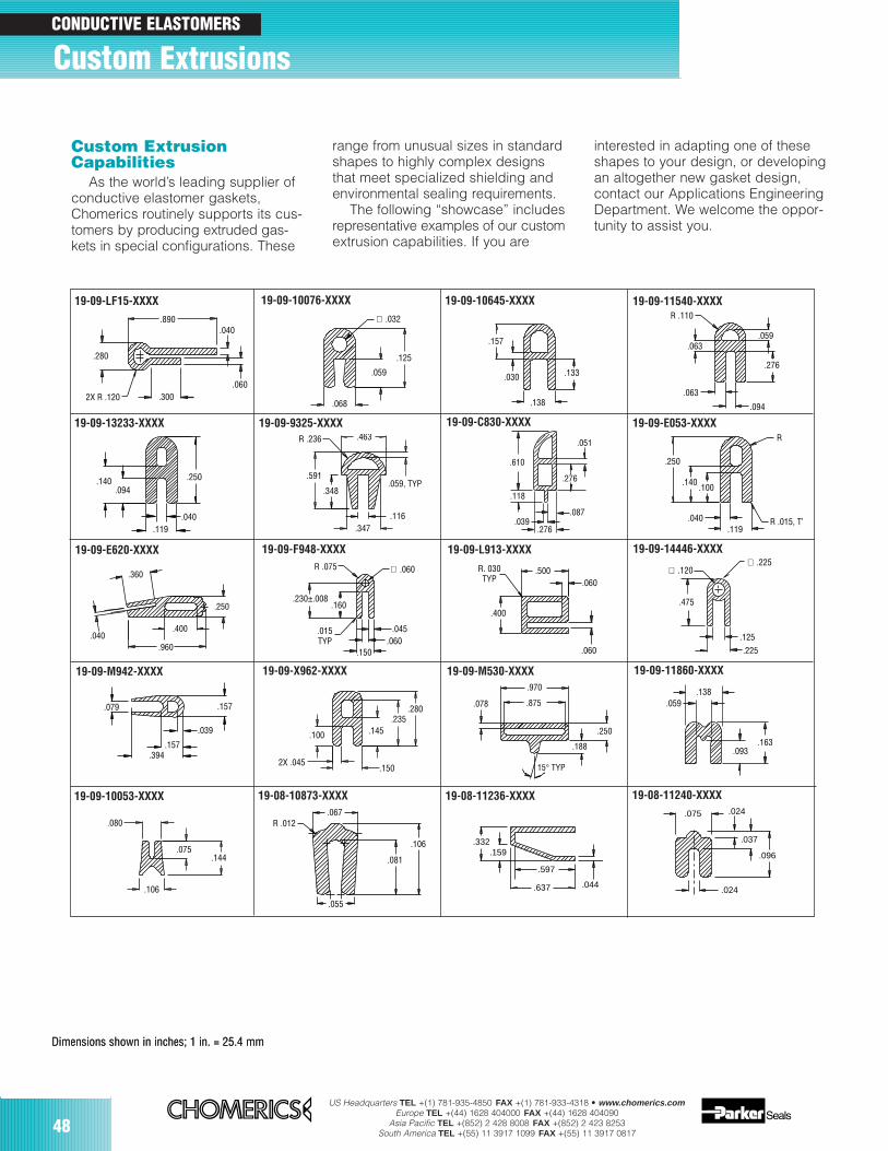
Custom shapes in endlessvariety (pages 48-54)Chomerics routinely produceselastomer extrusions in unusual sizesand intricate configurations to meetspecial needs. Refer to page 48 toexplore nearly 200 specializeddesigns for which tooling alreadyexists. This showcase illustrates thevariety and complexity that can beincorporated into extrudedelastomers.
CONDUCTIVE ELASTOMERS
Solid Rectangle
Hollow Rectangle
Channel
Hollow P
Open V
Flame-retardant gradeCHO-SEAL® 6370Chomerics introduced the firstconductive elastomer with a UL 94V-0rating* down to 0.014 inch (0.356 mm)thickness. This fully-extrudable materialis a corrosion-resistant, nickel-plated-graphite filled composite with shieldingeffectiveness equivalent to or betterthan other commercial grade gaskets:95 dB from 100 MHz to 10 GHz.UL File # 96ME 17043
Co-Extrusions streamlinedesign, reduce expense(pages 55-57)Co-extruded gaskets typically featurea conductive CHO-SEAL elastomer inparallel with a non-conductiveelastomer that provides additionalenvironmental sealing and corrosionprotection. Seam vulcanizationensures long-term integrity.
Co-extruded gaskets permit cost-effective use of existing flangedesigns, as well as attachment underthe less-expensive, non-conductivematerial. Compared to bonding andmounting separate gaskets, or double-groove designs, co-extruded gasketsoffer design, cost and handlingadvantages.
Full-Service FabricationOften cost-competitive for both smalland large volumes, conductiveelastomer extrusions are readilyfabricated for specific applications.These services are performed at thefactory or by Chomerics’ skilledauthorized fabricators throughoutNorth America and overseas.
Cut-to-length — Uniform parts aresupplied ready for installation. High-precision cut-to-length extrusions with
tolerances similar to molded parttolerances are available using thecutting technology of Parker Seal’s JBLDivision.
Spliced gaskets — For fabricatedgaskets with a minimum insidediameter of 2 inches (51 mm),extruded strips can be spliced to forma continuous seal. Spliced gasketsoffer cost savings over moldedgaskets without sacrificingperformance. In particular, splicedhollow extrusions yield lightweight, lowclosure force gaskets at considerablesavings. For solid extrusions, the spliceis often as strong and resilient as thegasket material’s tensile specification(except fluorosilicone).
Gaskets spliced by Chomerics orour authorized fabricators feature avulcanized joint, formed under heatand pressure, that ensures functionalityand a more uniform joint comparedwith adhesive bonding. For use withretention grooves, corner radii must beequal to or greater than 2.5 times thestrip width.
Frame assemblies — Chomericsfabricates complete frame/gasketassemblies either in their entirety orusing customer-supplied parts. Theseincorporate vulcanized joints andmiters, and often more than one gasketmaterial or profile. With experienceranging from handheld devices tofloor-standing equipment, size is not a limitation.

US Headquarters TEL +(1) 781-935-4850 FAX +(1) 781-933-4318 • www.chomerics.comEurope TEL +(44) 1628 404000 FAX +(44) 1628 404090
Asia Pacific TEL +(852) 2 428 8008 FAX +(852) 2 423 8253South America TEL +(55) 11 3917 1099 FAX +(55) 11 3917 0817
37
Bonded gaskets — Similar anddissimilar compositions and profilescan be bonded in parallel for specialrequirements. Capabilities includebonded-in compression stops, holesand other features.
Small, die-cut gaskets from flatextrusions — Standard rectangularextrusions up to 2 inches (51 mm)wide can provide an economicalmeans of producing die-cut gasketsfor some applications.
Precision washer cuts — Slicingsolid and hollow O-cross sections intodisks and washers can save time andcost, with tolerances equivalent tomolded parts. For extremely thin parts,<0.060 inch (1.52 mm), Chomericsaccesses the advanced productioncapabilities of Parker Seal’s JBLDivision (www.parker.com/jbl).
Kiss-cut grounding pads on tape— For manual “peel and stick” orrobotic “pick and place” application,
grounding pads are readily producedin quantity by kiss-cutting hollow D (orother) extrusions to their PSA releasetape. Features such as holes or slotscan be incorporated, and co-extrusions may be used. Continuouslengths are supplied on reels.
Speed assembly with creative and efficientattachment mechanisms ...
2-Part “Zipper” — Friction-fitdesigns using two gasketmaterials —conductive/conductive, conductive/non-conductive,fluorosilicone/silicone, etc.Especially appropriate for nuclear/biological/chemical (NBC)resistant applications or otherenvironmental concerns.
Friction-fit to a packaging feature — Gaskets that mount onintegral tangs accommodate thinwalls, limited space and intricatepackage shapes... without glue,rivets or tape.
Hollow “E” — Adhesive-free, aestheticdesign for attachment beneath an interiordoor “plate”, presenting an easilycompressed hollow profile.
Clip-on Gaskets — Choice ofconductive elastomer secured in arapidly installed, corrosion-resistant,stainless steel spring clip. Integralteeth bite through paint or surfaceoxides. Plastic clip-on strips are alsoavailable. The conductive elastomerextrusion is sandwiched between theenclosure flange and closed cover.
Metal Clip Extrusion — Conductiveelastomer with integral metal clip. Theclip provides mechanical attachmentthat conveniently replaces adhesiveor bonding measures.
Ribbed Profiles — Friction-fit optionfor exceptionally secure mounting ingrooves, available in a broad range ofChomerics’ high performanceconductive elastomers.
Our Applications Engineering specialists provide shielding gasket approaches that reduce overall manufacturing costs.
continued
Tight spaces, weight limits and housing material properties are no problem for Chomerics’ elastomerextrusions. Standard elastomer extrusions (except O-strips) can be ordered with pressure-sensitiveadhesive. Alternative mounting options offer cost-effective choices in materials and assembly, as well as cosmetic appearance. Here are just a few Chomerics designs that eliminate adhesives, screws andrivets, while adding considerable speed to system assembly. Refer also to the Custom ExtrusionsShowcase, pages 48-57.

38US Headquarters TEL +(1) 781-935-4850 FAX +(1) 781-933-4318 • www.chomerics.com
Europe TEL +(44) 1628 404000 FAX +(44) 1628 404090Asia Pacific TEL +(852) 2 428 8008 FAX +(852) 2 423 8253
South America TEL +(55) 11 3917 1099 FAX +(55) 11 3917 0817
EXTRUDED STRIPGASKETS inch (mm) TOLERANCE
Cut Length<1.000 (25.40) ±0.010 (0.25)1.0 to 30.000 (25.40 to 762) ±0.062 (1.58)> 30.000 (762) ±0.2% Nom. Dim.
Cross Section< 0.200 (5.08) ±0.005 (0.13)0.200-0.349 (5.08-8.86) ±0.008 (0.20)0.350-0.500 (8.89-12.70) ±0.010 (0.25)> 0.500 (12.70) ±3% Nom. Dim.
Table 1
Ordering ProcedureFor standard configurations, select
the Chomerics part number fromTables 7-16. The last four or fivedigits designate the material type.Orders must also specify quantity inlength (feet or meters). Please notethat minimum order quantities mayapply. Subject only to packagingconstraints, the gaskets are shippedin continuous lengths on reels.
For custom configurations, cut-to-length parts, or spliced strips,drawings must be provided. Partnumbers for these will be assignedby Chomerics.
General TolerancesThe table above provides generaltolerances for extruded conductiveelastomer gaskets. It is important tonote that all flat die-cut, molded, andextruded gaskets are subject to free-state variation in the unrestrainedcondition. The use of inspectionfixtures to verify conformance offinished parts is common andrecommended where appropriate.
Elastomer Extrusions continued
Material Selection andManufacturing Limitations
The extruded strips listed inthis section are generally availablein the CHO-SEAL and CHO-SILmaterials enumerated at the top ofthe next column, specifications forwhich are shown on pages 32-34.The physical characteristics ofcertain materials, however, makethem unextrudable in very smallsizes. General manufacturing
limitations are shown in Table 2(opposite). Specific materialexceptions (non-availability) aredenoted by numerical superscriptsfollowing certain part numbers inTables 7-16. The superscripts aredefined as follows:Code Material
1 1215, 1273, S6304, S6305, 6370, S6600
2 1217, 1221, 1224, 1350, L6303
3 1285, 1287, 1298, 1356, 1485
4 1401
Pressure-Sensitive Adhesive(PSA)
Chomerics’ extruded conductiveelastomer EMI gaskets are availablewith tenacious, non-conductivepressure-sensitive adhesive (PSA) tapefor permanent attachment. Typicalproperties for this adhesive are shownin Table 3. Peel strength data appearsin Table 4. These acrylic pressure-sensitive adhesives do not appreciablyaffect the through-flange resistance ofthe EMI gasket (see Table 5). Rapidthermal cycle testing does not affectpeel strength (see Table 6).
Pressure-Sensitive AdhesiveWidths, inch (mm)
0.090 (2.29) 0.220 (5.08)0.100 (2.54) 0.250 (6.35)0.125 (3.17) 0.500 (12.70)0.160 (4.06)
In general, pressure-sensitive adhesive requires a minimum of 0.125inch (3.17 mm) mating surface. For thisreason, Chomerics does not ordinarilysupply pressure-sensitive adhesive onsolid or hollow O-strips.
continued
PSA Ordering ProcedurePressure-sensitive adhesive may be
ordered for any standard extrusion(other than Solid and Hollow O-Strips)which has a 0.125 inch (3.17 mm)mating surface. The standard PartNumbers listed in Tables 9-15 must bemodified by Chomerics to designatepressure-sensitive adhesive. Contactus for this information.

US Headquarters TEL +(1) 781-935-4850 FAX +(1) 781-933-4318 • www.chomerics.comEurope TEL +(44) 1628 404000 FAX +(44) 1628 404090
Asia Pacific TEL +(852) 2 428 8008 FAX +(852) 2 423 8253South America TEL +(55) 11 3917 1099 FAX +(55) 11 3917 0817
39
Consult Chomerics’ Applications Engineering Department concerning materialcompatibility for smaller dimensions and custom extrusions.
*Maximum width of 1.00 (25.4) at minimum thickness of 0.031 (0.79).Dimensions shown in inches. 1 inch = 25.4 mm.
Table 2
������������������������������������������
H
W ����������������������������������������
H
W
WT
WT���������������������������������������������
Dia.W
������������������������������������������������
WT
������������������������������������������
Dia.
������������������������������������
ID
WT
T
�����������������������������������
����������������������������
ID
WT
T
������������������������������������������������������������������
EXTRUSION MANUFACTURING GUIDELINES & LIMITATIONS, inches (mm)Minimum dimensions allowed for manufacturing consistency
Solid D Hollow D Hollow Rect. Channel Solid O Hollow O Hollow P Rectangular
Mat’l H W WT H W Dia. WT WT W Dia. WT ID WT T ID T*
1215 0.035 0.035 0.020 0.040 0.040 0.020 0.025 0.020 0.020 0.028 0.015 0.020 0.020 0.030 0.045 0.031(0.89) (0.89) (0.51) (1.02) (1.02) (0.51) (0.64) (0.51) (0.51) (0.71) (0.38) (0.51) (0.51) (0.76) (1.14) (0.79)
1217 0.035 0.035 0.025 0.040 0.040 0.020 0.032 0.032 0.020 0.035 0.020 0.020 0.020 0.030 0.045 0.031(0.89) (0.89) (0.64) (1.02) (1.02) (0.51) (0.81) (0.81) (0.51) (0.89) (0.51) (0.51) (0.51) (0.76) (1.14) (0.79)
1221 0.035 0.035 0.025 0.040 0.040 0.020 0.032 0.032 0.020 0.035 0.020 0.020 0.020 0.030 0.045 0.031(0.89) (0.89) (0.64) (1.02) (1.02) (0.51) (0.81) (0.81) (0.51) (0.89) (0.51) (0.51) (0.51) (0.76) (1.14) (0.79)
1224 0.035 0.035 0.025 0.040 0.040 0.020 0.032 0.032 0.020 0.035 0.020 0.020 0.020 0.030 0.045 0.031(0.89) (0.89) (0.64) (1.02) (1.02) (0.51) (0.81) (0.81) (0.51) (0.89) (0.51) (0.51) (0.51) (0.76) (1.14) (0.79)
1273 0.035 0.035 0.020 0.040 0.040 0.020 0.025 0.020 0.020 0.028 0.015 0.020 0.020 0.030 0.045 0.031(0.89) (0.89) (0.51) (1.02) (1.02) (0.51) (0.64) (0.51) (0.51) (0.71) (0.38) (0.51) (0.51) (0.76) (1.14) (0.79)
1285 0.040 0.040 0.025 0.040 0.040 0.020 0.032 0.032 0.020 0.040 0.020 0.020 0.020 0.030 0.045 0.031(1.02) (1.02) (0.64) (1.02) (1.02) (0.51) (0.81) (0.81) (0.51) (1.02) (0.51) (0.51) (0.51) (0.76) (1.14) (0.79)
1287 0.040 0.040 0.025 0.040 0.040 0.020 0.032 0.032 0.020 0.040 0.020 0.020 0.020 0.030 0.045 0.031(1.02) (1.02) (0.64) (1.02) (1.02) (0.51) (0.81) (0.81) (0.51) (1.02) (0.51) (0.51) (0.51) (0.76) (1.14) (0.79)
1298 0.040 0.040 0.025 0.040 0.040 0.020 0.032 0.032 0.020 0.040 0.020 0.020 0.020 0.030 0.045 0.031(1.02) (1.02) (0.64) (1.02) (1.02) (0.51) (0.81) (0.81) (0.51) (1.02) (0.51) (0.51) (0.51) (0.76) (1.14) (0.79)
1350 0.035 0.035 0.025 0.040 0.040 0.020 0.032 0.032 0.020 0.035 0.020 0.020 0.020 0.030 0.045 0.031(0.89) (0.89) (0.64) (1.02) (1.02) (0.51) (0.81) (0.81) (0.51) (0.89) (0.51) (0.51) (0.51) (0.76) (1.14) (0.79)
1356 0.040 0.040 0.025 0.040 0.040 0.020 0.032 0.032 0.020 0.040 0.020 0.020 0.020 0.030 0.045 0.031(1.02) (1.02) (0.64) (1.02) (1.02) (0.51) (0.81) (0.81) (0.51) (1.02) (0.51) (0.51) (0.51) (0.76) (1.14) (0.79)
1401 0.062 0.062 0.045 0.040 0.040 0.020 0.045 0.045 0.020 0.062 0.045 0.020 0.045 0.045 0.045 0.045(1.57) (1.57) (1.14) (1.02) (1.02) (0.51) (1.14) (1.14) (0.51) (1.58) (1.14) (0.51) (1.14) (1.14) (1.14) (1.14)
1485 0.040 0.040 0.025 0.040 0.040 0.020 0.032 0.032 0.020 0.040 0.020 0.020 0.020 0.030 0.045 0.031(1.02) (1.02) (0.64) (1.02) (1.02) (0.51) (0.81) (0.81) (0.51) (1.02) (0.51) (0.51) (0.51) (0.76) (1.14) (0.79)
L6303 0.035 0.035 0.025 0.040 0.040 0.020 0.032 0.032 0.020 0.035 0.020 0.020 0.020 0.030 0.045 0.031(0.89) (0.89) (0.64) (1.02) (1.02) (0.51) (0.81) (0.81) (0.51) (0.89) (0.51) (0.51) (0.51) (0.76) (1.14) (0.79)
S6304 0.035 0.035 0.020 0.040 0.040 0.020 0.025 0.020 0.020 0.028 0.015 0.020 0.020 0.030 0.045 0.031(0.89) (0.89) (0.51) (1.02) (1.02) (0.51) (0.64) (0.51) (0.51) (0.71) (0.38) (0.51) (0.51) (0.76) (1.14) (0.79)
S6305 0.035 0.035 0.020 0.040 0.040 0.020 0.025 0.020 0.020 0.028 0.015 0.020 0.020 0.030 0.045 0.031(0.89) (0.89) (0.51) (1.02) (1.02) (0.51) (0.64) (0.51) (0.51) (0.71) (0.38) (0.51) (0.51) (0.76) (1.14) (0.79)
S6600 0.035 0.035 0.020 0.040 0.040 0.020 0.025 0.020 0.020 0.028 0.015 0.020 0.020 0.030 0.045 0.031(0.89) (0.89) (0.51) (1.02) (1.02) (0.51) (0.64) (0.51) (0.51) (0.71) (0.38) (0.51) (0.51) (0.76) (1.14) (0.79)
6370 0.035 0.035 0.020 0.040 0.040 0.020 0.025 0.020 0.020 0.028 0.015 0.020 0.020 0.030 0.045 0.031(0.89) (0.89) (0.51) (1.02) (1.02) (0.51) (0.64) (0.51) (0.51) (0.71) (0.38) (0.51) (0.51) (0.76) (1.14) (0.79)
E6434E For Solid O, min. dia. is 0.139 (3.53). For other cross sections, min. wall thickness is 0.062 (1.57). Not all cross sectionsare available. Contact Applications Engineering.

40US Headquarters TEL +(1) 781-935-4850 FAX +(1) 781-933-4318 • www.chomerics.com
Europe TEL +(44) 1628 404000 FAX +(44) 1628 404090Asia Pacific TEL +(852) 2 428 8008 FAX +(852) 2 423 8253
South America TEL +(55) 11 3917 1099 FAX +(55) 11 3917 0817
Surface Preparation ofMetallic Substrates
Optimal performance of the pressure-sensitive adhesive requires that thesubstrates to which these gaskets mustadhere are cleaned prior to application.Chomerics has developed specific,easy-to-follow procedures for preparingthe following substrates:■ Phosphate-Coated Steel■ Conversion-Coated Aluminum■ Stainless Steel and Mild Steel
It is essential to follow these cleaninginstructions to ensure maximumadhesion of the PSA to metal substrates.Failure to comply with the appropriatecleaning process could result in pooradhesion. Proper safety precautionsshould be followed to protect the operator.Materials Required:3M Scotch Brite Pads or equivalent,Rubber Gloves, Safety Glasses, Lint-Free Cotton Wipes; MEK, Acetone orIsopropyl Alcohol (IPA).
Surface Preparation ofConversion-Coated Aluminumand Phosphate-Coated SteelA. Using a clean, lint-free applicator,
moistened with MEK, acetonesolvent or IPA, wash the aluminumsurface until all traces of contam-ination have been removed.
B. Clean the surface until the cottonapplicator shows no discoloration.
C. If discoloration still exists, continuewashing, changing the cottonapplicator each time, until clean.Note: With phosphate coatings,it is very hard to remove alldiscoloration from the surface so itis up to the operator to determinethe cleanliness of the surface priorto bonding. Typically, cleaning thesurface 3 times is required.
D. Allow the substrate to drycompletely at room temperature.After the cleaning sequence iscomplete, do not touch thesubstrate with bare hands.
E. If the cleaned surfaces do not havethe PSA applied within an 8-hourperiod, rewash using the aboveprocess.
Surface Preparation of StainlessSteel and Mild Steel
A. Using a 3M Scotch Brite pad orequivalent, lightly abrade the steelsurface.
B. Blow the dust residue off the steelsurface with oil-free filtered air.
C. Follow Steps A through E fromprevious section to completesurface preparation.
Gasket Installation Procedure
A. Cut gasket material to specificlengths per drawing. If gasket is one piece (e.g., four corner
spliced gasket), pre-fit the assemblyto ensure fit and location.
B. Remove a portion of the releaseliner and position the gasket. Pressfirmly against gasket to tack inplace. Continue pressing alongentire length of gasket until it ispositioned and aligned to themating surface.
C. Using a rubber roller, apply moderate pressure to the entiregasket to ensure complete contactbetween the PSA and substrate.
Note: It is important during this rollingprocedure that the operator not applyexcessive pressure to the gasket.Extreme pressure will cause thegasket to elongate and creep as itrelaxes, which may cause anintermittent bond to the substratesurface.
Optimum Application Temperature
Temperatures below 50°F (10°C)can cause poor gasket adhesion to the substrate. Ideal gasketinstallation temperature is 72°F (22°C),ambient room temperature. Allmaterials should be stored at thistemperature when not in use.Hardware and gasket materials storedbelow 50°F should be brought to roomtemperature before installing gasket.
TYPICAL PEEL STRENGTH lb/inch (N/mm)
Property On Aluminum On Steel
Initial Peel Strength 6.0 (1.05) 6.0 (1.05)
Heat Aged Peel Strength* 5.4 (0.945) 5.4 (0.945)
Humidity Peel Strength** 6.0 (1.05) 6.0 (1.05)
Peel Strength Test Data Per ASTM D1000 (90° peel).* Heat aging 168 hrs / 158°F (70°C).
** Humidity 168 hrs/95% RH/ 158°F (70°C).
TYPICAL THROUGH FLANGEELECTRICAL RESISTANCE
Chomerics P/N 10-05-3369-S6304 @ 10% deflection @ 25% deflection(Ni/C filled silicone)
Hollow “D” Shape w/PSA 0.23 ohm 0.14 ohmExtrusion w/out PSA 0.16 ohm 0.14 ohm
RAPID THERMAL CYCLING* lb/inch (N/mm)
Conductive Elastomer Flange Peel Strength(90°)
CHO-SEAL 1485 Steel 7.0 (1.23)(Silver-Plated-Aluminum-Filled Silicone) Aluminum 7.0 (1.23)
CHO-SEAL S6304 Steel 6.5 (1.14)(Nickel-Plated-Graphite-Filled Silicone) Aluminum 5.5 (0.96)
*Per ASTM D1000; 5 cycles at –48° to 212°F (–40° to 100°C) with dwell time of15 minutes at each extreme.
Table 4
Table 5 Table 6
PRESSURE-SENSITIVE ADHESIVE TYPICAL PROPERTIES
Adhesive Description Pressure-sensitive acrylic with release liner
–20 to +150°F (–29 to +66°C); PSA will functionService Temperature Range for short periods of time @ 200°F (93°C);
ultimate high temperature limit 250°F (121°C)
Shelf Life Conditions One year at 158°F (70°C)/50% RH
Application Temperature Range 40 to 150°F (4 to 66°C)
Table 3
Elastomer Extrusions continued
(PSA Attachment, continued)
Instructions for Surface Preparation and Installing Gaskets with PSA

US Headquarters TEL +(1) 781-935-4850 FAX +(1) 781-933-4318 • www.chomerics.comEurope TEL +(44) 1628 404000 FAX +(44) 1628 404090
Asia Pacific TEL +(852) 2 428 8008 FAX +(852) 2 423 8253South America TEL +(55) 11 3917 1099 FAX +(55) 11 3917 0817
41continued
(mm dimensions in parentheses)
SOLID O-STRIPS
Chomerics P/N* “Rule of Thumb” MIL P/N: M83528 Nominal Groove Dimensions††
001X†-( ) Dimension [Dia.] Depth Width
10-04-2866-XXXX 0.112 0.092 0.121(2.84) (2.34) (3.07)
10-04-3077-XXXX 0.119 0.098 0.128(008) (3.02) (2.49) (3.25)
10-04-2463-XXXX 0.125 0.102 0.135(009) (3.18) (2.59) (3.43)
10-04-2862-XXXX 0.130 0.107 0.138(3.30) (2.72) (3.51)
19-04-12903-XXXX 0.134 0.110 0.143(3.40) (2.79) (3.63)
10-04-1721-XXXX 0.139 0.114 0.147(010) (3.53) (2.90) (3.73)
19-04-12904-XXXX 0.147 0.120 0.156(3.73) (3.05) (3.96)
10-04-3982-XXXX 0.150 0.123 0.158(3.81) (3.12) (4.01)
19-04-12906-XXXX 0.158 0.129 0.166(4.01) (3.28) (4.22)
19-04-12905-XXXX 0.159 0.130 0.167(4.04) (3.30) (4.24)
10-04-3231-XXXX 0.160 0.131 0.168(4.06) (3.33) (4.27)
19-04-12907-XXXX 0.170 0.139 0.178(4.32) (3.53) (4.52)
19-04-F371-XXXX 0.188 0.154 0.195(011) (4.78) (3.91) (4.95)
19-04-12908-XXXX 0.195 0.160 0.201(4.95) (4.06) (5.11)
10-04-2864-XXXX 0.216 0.177 0.227(012) (5.49) (4.50) (5.77)
19-04-12909-XXXX 0.219 0.179 0.231(5.56) (4.55) (5.87)
19-04-11453-XXXX 0.220 0.180 0.232(5.59) (4.57) (5.89)
19-04-12910-XXXX 0.236 0.193 0.247(5.99) (4.90) (6.27)
19-04-12911-XXXX 0.247 0.202 0.258(6.27) (5.13) (6.55)
10-04-3076-XXXX 0.250 0.205 0.260(013) (6.35) (5.21) (6.60)
SOLID O-STRIPS
Table 7
* Replace XXXX with four or five digit material number (1356, 1273, S6305, etc.).Smallest sizes may not be extrudable in certain materials. For explanation ofsuperscript codes following XXXX, which indicate non-availability, refer to page 38.
† “X” should be replaced by applicable MIL-G-83528B material type (e.g., A, B, C,etc.). Number in parentheses is MIL-G-83528B dash number, which should beinserted (without parentheses) at end of MIL P/N.
†† Note: The groove dimensions recommended assume groove tolerance of ±0.002 in.(0.05 mm) for standard solid O- and D-strips. Closure forces are assumed toprovide maximum and uniform gasket deflection. If these conditions are notattainable,contact Chomerics’ Applications Engineering Department before ordering.
������������������������������������������
Dia.
continued
continued
Standard Extrusion Sizes
Additional sizes may be available. Please inquire.
Chomerics P/N* “Rule of Thumb” MIL P/N: M83528 Nominal Groove Dimensions††
001X†-( ) Dimension [Dia.] Depth Width
19-04-12895-XXXX2,3,4 0.028 0.018 0.055(0.71) (0.46) (1.40)
19-04-W993-XXXX2,3,4 0.030 0.020 0.056(0.76) (0.51) (1.42)
19-04-12896-XXXX2,3,4 0.032 0.022 0.056(0.81) (0.56) (1.42)
19-04-12897-XXXX2,3,4 0.033 0.023 0.056(0.84) (0.58) (1.42)
10-04-6386-XXXX 0.040 0.029 0.061(001) (1.02) (0.74) (1.55)
10-04-9139-XXXX 0.048 0.037 0.065(1.22) (0.94) (1.65)
10-04-C317-XXXX 0.050 0.038 0.068(1.27) (0.97) (1.73)
10-04-3560-XXXX 0.053 0.041 0.070(002) (1.35) (1.04) (1.78)
19-04-X294-XXXX 0.060 0.047 0.076(1.52) (1.19) (1.93)
10-04-2561-XXXX 0.062 0.049 0.077(003) (1.57) (1.24) (1.96)
10-04-1687-XXXX 0.070 0.056 0.084(004) (1.78) (1.42) (2.13)
19-04-12898-XXXX 0.074 0.060 0.087(1.88) (1.52) (2.21)
19-04-11228-XXXX 0.075 0.061 0.087(1.91) (1.55) (2.21)
19-04-12899-XXXX 0.077 0.063 0.089(1.96) (1.60) (2.26)
19-04-12900-XXXX 0.079 0.064 0.091(2.01) (1.63) (2.31)
10-04-2657-XXXX 0.080 0.065 0.092(005) (2.03) (1.65) (2.34)
19-04-12901-XXXX 0.085 0.069 0.097(2.16) (1.75) (2.46)
19-04-M394-XXXX 0.090 0.073 0.102(2.29) (1.85) (2.59)
10-04-2865-XXXX 0.093 0.076 0.104(006) (2.36) (1.93) (2.64)
10-04-3509-XXXX 0.100 0.082 0.110(2.54) (2.08) (2.79)
10-04-1720-XXXX 0.103 0.084 0.114(007) (2.62) (2.13) (2.90)
19-04-12902-XXXX 0.106 0.087 0.114(2.69) (2.21) (2.90)
Table 7 continued

42US Headquarters TEL +(1) 781-935-4850 FAX +(1) 781-933-4318 • www.chomerics.com
Europe TEL +(44) 1628 404000 FAX +(44) 1628 404090Asia Pacific TEL +(852) 2 428 8008 FAX +(852) 2 423 8253
South America TEL +(55) 11 3917 1099 FAX +(55) 11 3917 0817
Conductive Elastomer Extruded Strips continued
HOLLOW O-STRIPS
19-04-11285-XXXX2,3,4 0.040 (1.02) 0.013 (0.33)
10-04-W201-XXXX2,3,4 0.053 (1.35) 0.032 (0.81)
10-04-W137-XXXX4 0.060 (1.52) 0.020 (0.51)
10-04-W163-XXXX2,3,4 0.062 (1.57) 0.035 (0.89)
19-04-14964-XXXX4 0.070 (1.78) 0.020 (0.51)
10-04-W202-XXXX2,3,4 0.073 (1.85) 0.049 (1.24)
19-04-13803-XXXX2,3,4 0.074 (1.88) 0.040 (1.02)
19-04-15465-XXXX4 0.080 (2.03) 0.030 (0.76)
19-04-14206-XXXX4 0.080 (2.03) 0.040 (1.02)
19-04-11204-XXXX4 0.081 (2.06) 0.020 (0.51)
19-04-12570-XXXX2,3,4 0.083 (2.11) 0.050 (1.27)
19-04-11220-XXXX4 0.090 (2.29) 0.050 (1.27)
10-04-W267-XXXX4 0.090 (2.29) 0.050 (1.27)
10-04-W293-XXXX2,3,4 0.090 (2.29) 0.060 (1.52)
10-04-W203-XXXX2,3,4 0.093 (2.36) 0.061 (1.55)
19-04-16162-XXXX2,3,4 0.100 (2.54) 0.070 (1.78)
19-04-11205-XXXX4 0.102 (2.60) 0.039 (0.99)
10-04-8363-XXXX4 (007) 0.103 (2.62) 0.040 (1.02)
10-04-M211-XXXX4 0.103 (2.62) 0.040 (1.02)
19-04-10212-XXXX4 0.110 (2.79) 0.045 (1.14)
19-04-11218-XXXX4 0.110 (2.79) 0.045 (1.14)
19-04-14120-XXXX4 0.110 (2.79) 0.062 (1.57)
19-04-15278-XXXX4 0.110 (2.79) 0.068 (1.73)
19-04-12534-XXXX2,3,4 0.118 (3.00) 0.079 (2.01)
19-04-11216-XXXX4 0.122 (3.10) 0.061 (1.55)
19-04-11287-XXXX4 0.122 (3.10) 0.061 (1.55)
10-04-2999-XXXX4 (001) 0.125 (3.18) 0.045 (1.14)
10-04-8817-XXXX4 (006) 0.125 (3.18) 0.062 (1.57)
19-04-13564-XXXX4 0.125 (3.18) 0.070 (1.78)
10-04-W204-XXXX4 0.125 (3.18) 0.078 (1.98)
19-04-11283-XXXX4 0.125 (3.18) 0.080 (2.03)
10-04-W775-XXXX4 0.125 (3.18) 0.085 (2.16)
10-04-5514-XXXX4 0.130 (3.30) 0.045 (1.14)
19-04-16390-XXXX 0.135 (3.43) 0.045 (1.14)
19-04-16009-XXXX4 0.135 (3.43) 0.085 (2.16)
19-04-X787-XXXX2,3,4 0.135 (3.43) 0.097 (2.46)
19-04-14632-XXXX4 0.137(3.48) 0.087 (2.21)
19-04-11289-XXXX4 0.145 (3.68) 0.070 (1.78)
19-04-13118-XXXX4 0.145 (3.68) 0.080 (2.03)
Table 8 ������������������������������������
B A
Chomerics P/N*MIL P/N: M83528
Nominal Dimensions
011X†-( ) A B
SOLID O-STRIPS
Table 7 continued
Chomerics P/N* “Rule of Thumb” MIL P/N: M83528 Nominal Groove Dimensions††
001X†-( ) Dimension [Dia.] Depth Width
10-04-9769-XXXX 0.280 0.230 0.288(7.11) (5.84) (7.32)
19-04-12912-XXXX 0.291 0.238 0.300(7.39) (6.05) (7.62)
19-04-12913-XXXX 0.292 0.239 0.301(7.42) (6.07) (7.65)
19-04-12914-XXXX 0.317 0.260 0.324(8.05) (6.60) (8.23)
19-04-12915-XXXX 0.324 0.265 0.332(8.23) (6.73) (8.43)
19-04-12916-XXXX 0.329 0.270 0.335(8.36) (6.86) (8.51)
19-04-12917-XXXX 0.348 0.285 0.354(8.84) (7.24) (8.99)
19-04-12918-XXXX 0.367 0.301 0.376(9.32) (7.65) (9.55)
19-04-12919-XXXX 0.379 0.310 0.388(9.63) (7.87) (9.86)
19-04-12920-XXXX 0.393 0.322 0.401(9.98) (8.18) (10.19)
19-04-12921-XXXX 0.410 0.336 0.417(10.41) (8.53) (10.59)
19-04-12922-XXXX 0.420 0.344 0.427(10.67) (8.74) (10.85)
19-04-W337-XXXX 0.429 0.351 0.436(10.90) (8.92) (11.07)
19-04-12923-XXXX 0.479 0.392 0.484(12.17) (9.96) (12.29)
19-04-12924-XXXX 0.570 0.467 0.590(14.48) (11.86) (14.99)
19-04-12925-XXXX 0.635 0.520 0.653(16.13) (13.21) (16.59)
19-04-12926-XXXX 0.661 0.542 0.677(16.79) (13.77) (17.20)
19-04-12927-XXXX 0.831 0.681 0.860(21.11) (17.30) (21.84)
19-04-12928-XXXX 0.876 0.718 0.903(22.25) (18.24) (22.94)
19-04-12929-XXXX 0.894 0.733 0.920(22.71) (18.62) (23.37)
19-04-12930-XXXX 0.922 0.756 0.947(23.42) (19.20) (24.05)
* Replace XXXX with four or five digit material number (1356, 1273, S6305, etc.).Smallest sizes may not be extrudable in certain materials. For explanation ofsuperscript codes following XXXX, which indicate non-availability, refer to page 38.
† “X” should be replaced by applicable MIL-G-83528B material type (e.g., A, B, C,etc.). Number in parentheses is MIL-G-83528B dash number, which should beinserted (without parentheses) at end of MIL P/N.
†† Note: The groove dimensions recommended assume groove tolerance of ±0.002 in.(0.05 mm) for standard solid O- and D-strips. Closure forces are assumed toprovide maximum and uniform gasket deflection. If these conditions are notattainable, contact Chomerics’ Applications Engineering Department beforeordering.
(mm dimensions in parentheses)
Additional sizes may be available. Please inquire.
continued

US Headquarters TEL +(1) 781-935-4850 FAX +(1) 781-933-4318 • www.chomerics.comEurope TEL +(44) 1628 404000 FAX +(44) 1628 404090
Asia Pacific TEL +(852) 2 428 8008 FAX +(852) 2 423 8253South America TEL +(55) 11 3917 1099 FAX +(55) 11 3917 0817
43
“MUSHROOM” D-STRIPS †
(mm dimensions in parentheses)
HOLLOW O-STRIPS
19-04-14930-XXXX4 0.151 (3.84) 0.094 (2.39)
19-04-13545-XXXX2,3,4 0.153 (3.89) 0.115 (2.92)
10-04-4180-XXXX (002) 0.156 (3.96) 0.050 (1.27)
10-04-9732-XXXX4 0.156 (3.96) 0.080 (2.03)
19-04-11213-XXXX2,3,4 0.172 (4.37) 0.140 (3.56)
19-04-11293-XXXX2,3,4 0.175 (4.45) 0.144 (3.66)
10-04-8133-XXXX (008) 0.177 (4.50) 0.079 (2.01)
19-04-11415-XXXX 0.177 (4.50) 0.079 (2.01)
19-04-13189-XXXX4 0.177 (4.50) 0.110 (2.79)
19-04-11214-XXXX4 0.180 (4.57) 0.140 (3.56)
19-04-14537-XXXX4 0.189 (4.80) 0.111 (2.82)
10-04-4254-XXXX 0.190 (4.83) 0.080 (2.03)
19-04-12015-XXXX 0.207 (5.26) 0.077 (1.95)
19-04-15435-XXXX 0.207 (5.26) 0.090 (2.27)
19-04-E483-XXXX 0.210 (5.33) 0.093 (2.36)
19-04-15479-XXXX 0.210 (5.33) 0.120 (3.05)
19-04-C627-XXXX 0.216 (5.49) 0.090 (2.27)
10-04-2737-XXXX (003) 0.250 (6.35) 0.125 (3.18)
19-04-15434-XXXX 0.250 (6.35) 0.140 (3.56)
19-04-15443-XXXX4 0.250 (6.35) 0.187 (4.75)
19-04-14349-XXXX4 0.250 (6.35) 0.200 (5.08)
19-04-W049-XXXX 0.290 (7.36) 0.156 (3.96)
10-04-3221-XXXX 0.290 (7.36) 0.175 (4.45)
10-04-3004-XXXX (004) 0.312 (7.92) 0.192 (4.88)
19-04-13759-XXXX 0.348 (8.84) 0.250 (6.35)
19-04-14292-XXXX 0.373 (9.47) 0.200 (5.08)
10-04-3122-XXXX (005) 0.375 (9.53) 0.250 (6.35)
19-04-14467-XXXX 0.394 (10.01) 0.253 (6.43)
19-04-14290-XXXX 0.404 (10.26) 0.243 (6.17)
19-04-14291-XXXX 0.405 (10.29) 0.223 (5.66)
19-04-12338-XXXX 0.430 (10.92) 0.330 (8.38)
10-04-4034-XXXX 0.437 (11.10) 0.347 (8.81)
19-04-14731-XXXX 0.438 (11.13) 0.275 (6.99)
19-04-14138-XXXX 0.440 (11.18) 0.280 (7.11)
19-04-14261-XXXX 0.461 (11.71) 0.295 (7.49)
19-04-14139-XXXX 0.461 (11.71) 0.315 (8.00)
10-04-3649-XXXX 0.470 (11.94) 0.345 (8.76)
10-04-5572-XXXX 0.500 (12.70) 0.385 (9.78)
19-04-11651-XXXX 0.524 (13.31) 0.315 (8.00)
10-04-4155-XXXX 0.555 (14.10) 0.425 (10.80)
10-04-5515-XXXX 0.562 (14.27) 0.437 (11.10)
Table 8 continued
* Replace XXXX with four or five digit material number (1356, 1273, S6305,etc.). Smallest sizes may not be extrudable in certain materials. Forexplanation of superscript codes following XXXX, which indicate non-availability, refer to page 38.
continued
Pressure-Sensitive Adhesive is available on anyextrusion with a minimum 0.125 inch (3.17 mm) matingsurface. Contact Chomerics to obtain modified PartNumbers. Refer to pages 38 and 40 for details.
Chomerics P/N*MIL P/N: M83528
Nominal Dimensions
011X†-( ) A B
Nominal DimensionsChomerics P/N* A B C D
19-09-16503-XXXX4 0.265 0.312 0.113 0.040(6.73) (7.92) (2.87) (1.02)
19-09-16802-XXXX 0.315 0.301 0.109 0.053(8.00) (7.65) (2.77) (1.35)
19-05-14587-XXXX 0.487 0.324 0.115 0.050(12.37) (8.23) (2.92) (1.27)
19-09-14377-XXXX 0.625 0.375 0.106 0.057(15.88) (9.53) (2.69) (1.45)
19-09-14926-XXXX 0.625 0.400 0.106 0.057(15.88) (10.16) (2.69) (1.45)
19-09-15486-XXXX 0.846 0.472 0.120 0.053(21.49) (11.99) (3.05) (1.35)
19-09-15523-XXXX 0.890 0.730 0.183 0.065(22.61) (18.54) (4.65) (1.65)
B
C
D
A��������������������������������������������������������
Table 9
† U.S. Patent No. 06075205
Additional sizes may be available. Please inquire.
HOLLOW O-STRIPS
19-04-13764-XXXX 0.620 (15.75) 0.250 (6.35)
10-04-5516-XXXX 0.620 (15.75) 0.515 (13.08)
19-04-15181-XXXX 0.625 (15.88) 0.250 (6.35)
19-04-14326-XXXX 0.630 (16.00) 0.340 (8.64)
10-04-3652-XXXX 0.650 (16.51) 0.520 (13.21)
19-04-15342-XXXX 1.058 (26.87) 0.918 (23.32)
Chomerics P/N*MIL P/N: M83528
Nominal Dimensions
011X†-( ) A B
Table 8 continued
* Replace XXXX with four or five digit material number (1356, 1273, S6305,etc.). Smallest sizes may not be extrudable in certain materials. Forexplanation of superscript codes following XXXX, which indicate non-availability, refer to page 38.
† “X” should be replaced by applicable MIL-G-83528B material type (e.g., A,B, C, etc.). Number in parentheses is MIL-G-83528B dash number, whichshould be inserted (without parentheses) at end of MIL P/N.
continued

44US Headquarters TEL +(1) 781-935-4850 FAX +(1) 781-933-4318 • www.chomerics.com
Europe TEL +(44) 1628 404000 FAX +(44) 1628 404090Asia Pacific TEL +(852) 2 428 8008 FAX +(852) 2 423 8253
South America TEL +(55) 11 3917 1099 FAX +(55) 11 3917 0817
������������������������������������������
H
W
R
HOLLOW D-STRIPS
Nominal Dimensions
19-05-15343-XXXX 0.125 0.094 0.062 0.040(3.18) (2.39) (1.58) (1.02)
19-05-14960-XXXX2,3,4 0.157 — 0.086 0.020(3.99) (2.18) (0.51)
10-05-6419-XXXX 0.156 0.078 0.078 0.045(001) (3.96) (1.98) (1.98) (1.14)
10-05-4202-XXXX 0.187 0.093 0.093 0.050(002) (4.75) (2.36) (2.36) (1.27)
19-05-X254-XXXX4 0.187 0.134 0.093 0.040(4.75) (3.43) (2.36) (1.02)
19-04-11231-XXXX 0.207 0.084 0.103 0.050(5.26) (2.13) (2.62) (1.27)
SOLID D-STRIPS
(mm dimensions in parentheses)
A
�����������������������������������
C
B
D
Table 11
Pressure-Sensitive Adhesive is available on any extrusion with a minimum 0.125 inch (3.17 mm) mating surface.Contact Chomerics to obtain modified Part Numbers. Refer to pages 38 and 40 for details.
“Rule of Thumb”Nominal Groove
Dimensions Dimensions ††
H W R(rad.) Depth Width
10-05-2618-XXXX 0.110 0.150 0.075 0.095 0.165(006) (2.79) (3.81) (1.91) (2.41) (4.19)
19-05-F173-XXXX 0.156 0.156 0.078 0.137 0.194(009) (3.96) (3.96) (1.98) (3.48) (4.93)
10-05-1577-XXXX 0.175 0.178 0.089 0.154 0.195(010) (4.45) (4.52) (2.26) (3.91) (4.95)
19-05-A381-XXXX 0.200 0.187 0.093 0.177 0.228(5.08) (4.75) (2.36) (4.50) (5.79)
19-05-12899-XXXX 0.205 0.187 0.093 0.179 0.234(5.21) (4.75) (2.36) (4.55) (5.94)
19-05-W469-XXXX 0.188 0.188 0.094 0.166 0.229(011) (4.78) (4.78) (2.39) (4.22) (5.82)
19-05-12890-XXXX 0.324 0.487 0.243 0.289 0.577(8.23) (12.37) (6.17) (7.34) (14.66)
Table 10 continued
SOLID D-STRIPS
“Rule of Thumb”Nominal Groove
Dimensions Dimensions † †
H W R(rad.) Depth Width
19-05-14769-XXXX3,4 0.062 0.035 0.018 0.028 0.076(1.57) (0.89) (0.46) (0.71) (1.93)
10-05-5589-XXXX4 0.064 0.055 0.031 0.052 0.077(1.63) (1.40) (0.79) (1.32) (1.96)
10-05-Z337-XXXX4 0.075 0.060 0.030 0.062 0.089(1.90) (1.52) (0.76) (1.57) (2.26)
10-05-1362-XXXX 0.068 0.062 0.031 0.056 0.084(1.73) (1.57) (0.79) (1.42) (2.13)
19-05-E163-XXXX 0.074 0.062 0.031 0.061 0.088(1.88) (1.57) (0.78) (1.55) (2.23)
19-05-12883-XXXX 0.085 0.062 0.031 0.072 0.088(2.16) (1.57) (0.78) (1.83) (2.23)
10-05-4699-XXXX 0.100 0.062 0.031 0.085 0.081(2.54) (1.57) (0.79) (2.16) (2.06)
19-05-12887-XXXX4 0.055 0.064 0.032 0.044 0.101(1.40) (1.62) (0.81) (1.12) (2.57)
10-05-E205-XXXX 0.095 0.070 0.035 0.081 0.097(2.41) (1.78) (0.89) (2.06) (2.46)
10-05-1363-XXXX 0.089 0.078 0.039 0.074 0.101(003) (2.26) (1.98) (0.99) (1.88) (2.57)
19-05-C497-XXXX 0.070 0.080 0.040 0.058 0.116(1.78) (2.03) (1.02) (1.47) (2.95)
19-05-E329-XXXX 0.090 0.080 0.040 0.076 0.111(2.29) (2.03) (1.02) (1.93) (2.82)
19-05-12888-XXXX 0.081 0.088 0.044 0.068 0.123(2.06) (2.23) (1.12) (1.73) (3.12)
19-05-A611-XXXX 0.134 0.091 0.045 0.117 0.118(3.40) (2.31) (1.14) (2.97) (3.00)
10-05-3224-XXXX 0.078 0.094 0.047 0.065 0.115(002) (1.98) (2.39) (1.19) (1.65) (2.92)
19-05-Z586-XXXX 0.094 0.094 0.047 0.080 0.128(004) (2.39) (2.39) (1.19) (2.03) (3.25)
19-05-C128-XXXX 0.115 0.102 0.051 0.099 0.134(2.92) (2.60) (1.30) (2.51) (3.40)
10-05-1499-XXXX 0.156 0.118 0.059 0.137 0.136(008) (3.96) (3.00) (1.50) (3.48) (3.45)
10-05-A283-XXXX 0.131 0.122 0.061 0.114 0.156(3.33) (3.10) (1.55) (2.90) (3.96)
10-05-1364-XXXX 0.135 0.122 0.061 0.118 0.140(007) (3.43) (3.10) (1.55) (3.00) (3.56)
19-05-F364-XXXX 0.135 0.124 0.062 0.118 0.158(3.43) (3.15) (1.57) (3.00) (4.01)
19-05-F084-XXXX 0.125 0.125 0.062 0.108 0.161(3.18) (3.18) (1.57) (2.74) (4.09)
Table 10
* Replace XXXX with four or five digit material number (1356, 1273, S6305,etc.). Smallest sizes may not be extrudable in certain materials. Forexplanation of superscript codes following XXXX, which indicate non-availability, refer to page 38.
† “X” should be replaced by applicable MIL-G-83528B material type (e.g., A,B, C, etc.). Number in parentheses is MIL-G-83528B dash number, whichshould be inserted (without parentheses) at end of MIL P/N.
†† Note: The groove dimensions recommended assume groove tolerance of±0.002" (0.05 mm) for standard solid O- and D-strips. Closure forces areassumed to provide maximum and uniform gasket deflection. If theseconditions are not attainable, contact Chomerics’ Applications EngineeringDepartment before ordering.
Chomerics P/N*MIL P/N: M83528003X†-( )
Additional sizes may be available. Please inquire.
Chomerics P/N*MIL P/N: M83528003X†-( )
A B C (rad.) DChomerics P/N*MIL P/N: M83528007X†-( )
Conductive Elastomer Extruded Strips continued

US Headquarters TEL +(1) 781-935-4850 FAX +(1) 781-933-4318 • www.chomerics.comEurope TEL +(44) 1628 404000 FAX +(44) 1628 404090
Asia Pacific TEL +(852) 2 428 8008 FAX +(852) 2 423 8253South America TEL +(55) 11 3917 1099 FAX +(55) 11 3917 0817
45
CHANNEL STRIPS
HOLLOW D-STRIPS
(mm dimensions in parentheses)
continued
* Replace XXXX with four or five digit material number (1356, 1273, S6305,etc.). Smallest sizes may not be extrudable in certain materials. Forexplanation of superscript codes following XXXX, which indicate non-availability, refer to page 38.
** Dimension “A” measured at bottom (width narrows to become tangent to“C” radius).
† “X” should be replaced by applicable MIL-G-83528B material type (e.g., A, B,C, etc.). Number in parentheses is MIL-G-83528B dash number, which shouldbe inserted (without parentheses) at end of MIL P/N.
†† Includes internal radii for low closure properties.
19-08-14054-XXXX4 0.075 0.099 0.025 0.032(1.91) (2.51) (0.64) (0.81)
10-08-6475-XXXX4 0.100 0.100 0.034 0.033(001) (2.54) (2.54) (0.86) (0.84)
19-08-12880-XXXX4 0.126 0.078 0.044 0.048(3.20) (1.98) (1.12) (1.22)
19-08-12881-XXXX4 0.126 0.099 0.047 0.059(3.20) (2.51) (1.19) (1.50)
10-08-8340-XXXX4 0.126 0.097 0.026 0.037(3.20) (2.46) (0.66) (0.94)
10-08-3215-XXXX 0.126 0.110 0.025 0.050(002) (3.20) (2.79) (0.64) (1.27)
10-08-4315-XXXX 0.126 0.225 0.020 0.075(003) (3.20) (5.72) (0.51) (1.91)
19-08-12882-XXXX4 0.154 0.154 0.082 0.088(3.91) (3.91) (2.08) (2.24)
10-08-3157-XXXX 0.156 0.156 0.062 0.047(004) (3.96) (3.96) (1.57) (1.19)
19-08-12844-XXXX 0.156 0.175 0.046 0.075(3.96) (4.45) (1.17) (1.90)
10-08-3253-XXXX 0.175 0.156 0.047 0.075(005) (4.45) (3.96) (1.19) (1.91)
10-08-F815-XXXX 0.188 0.188 0.062 0.062(4.78) (4.78) (1.57) (1.57)
19-08-12884-XXXX4 0.193 0.193 0.128 0.064(4.90) (4.90) (3.25) (1.62)
19-08-12158-XXXX4 0.250 0.250 0.170 0.062(6.35) (6.35) (4.32) (1.57)
19-08-C929-XXXX 0.250 0.250 0.130 0.062(6.35) (6.25) (3.30) (1.57)
19-08-12885-XXXX 0.260 0.184 0.140 0.062(6.60) (4.67) (3.56) (1.57)
19-08-12886-XXXX 0.320 0.315 0.193 0.197(8.13) (8.00) (4.90) (5.00)
10-08-3872-XXXX** 0.327 0.235 0.062 0.115(006) (8.31) (5.97) (1.57) (2.92)
19-08-E622-XXXX0.375 0.500 0.187 0.125(9.53) (12.7) (4.75) (3.18)
Table 12
* Replace XXXX with four or five digit material number (1356, 1273,S6305, etc.). Smallest sizes may not be extrudable in certain materials.For explanation of superscript codes following XXXX, which indicate non-availability, refer to page 38.
** Slot not centered. Centerline of slot is 0.167 in. (4.24mm)from left edge.
† “X” should be replaced by applicable MIL-G-83528B material type (e.g., A,B, C, etc.). Number in parentheses is MIL-G-83528B dash number, whichshould be inserted (without parentheses) at end of MIL P/N.
A
B
C
������������������������������������������������
D
19-05-11440-XXXX4 0.246 0.020 0.125 0.030(6.25) (0.51) (3.18) (0.76)
10-05-6991-XXXX 0.250 0.125 0.125 0.062(6.35) (3.18) (3.18) (1.57)
10-05-6394-XXXX 0.250 0.125 0.125 0.065(007) (6.35) (3.18) (3.18) (1.65)
19-05-10277-XXXX4 0.296 0.015 0.172 0.030(7.52) (0.38) (4.37) (0.76)
19-05-L467-XXXX 0.296 0.015 0.172 0.050(7.52) (0.38) (4.37) (1.27)
10-05-3369-XXXX†† 0.312 0.156 0.156 0.062(004) (7.92) (3.96) (3.96) (1.57)
10-05-4308-XXXX 0.312 0.156 0.156 0.062(003) (7.92) (3.96) (3.96) (1.57)
10-05-4318-XXXX** 0.312 0.200 0.112 0.062(005) (7.92) (5.08) (2.84) (1.57)
19-05-16720-XXXX4 0.400 0.025 0.205 0.035(10.16) (0.64) (5.21) (0.89)
19-05-12066-XXXX 0.487 0.080 0.244 0.045(12.37) (2.03) (6.20) (1.14)
19-05-16657-XXXX 0.487 0.080 0.244 0.055(12.36) (2.03) (6.20) (1.40)
19-05-12375-XXXX 0.487 0.080 0.244 0.062(12.37) (2.03) (6.20) (1.57)
10-05-4542-XXXX 0.487 0.080 0.244 0.080(006) (12.37) (2.03) (6.20) (2.03)
10-05-C589-XXXX 0.488 0.068 0.244 0.055(12.40) (1.73) (6.20) (1.40)
10-05-C038-XXXX 0.488 0.080 0.244 0.080(12.40) (2.03) (6.20) (2.03)
19-05-E429-XXXX 0.502 0.250 0.250 0.061(12.75) (6.35) (6.35) (1.55)
10-05-4282-XXXX 0.700 0.250 0.350 0.100(17.78) (6.35) (8.89) (2.54)
19-05-13856-XXXX 0.750 0.375 0.375 0.050(19.05) (9.53) (9.53) (12.70)
19-05-L362-XXXX 0.750 0.375 0.375 0.075(19.05) (9.53) (9.53) (1.91)
19-05-W379-XXXX 0.975 0.132 0.488 0.093(24.77) (3.35) (12.40) (2.36)
Table 11 continued
Chomerics P/N*MIL P/N: M83528007X†-( )
Nominal Dimensions
A B C (rad.) D
Chomerics P/N*MIL P/N: M83528010X†-( ) A B C D
Nominal Dimensions
Pressure-Sensitive Adhesive is available on any extrusion with a minimum 0.125 inch (3.17 mm) mating surface.Contact Chomerics to obtain modified Part Numbers. Refer to pages 38 and 40 for details.

46US Headquarters TEL +(1) 781-935-4850 FAX +(1) 781-933-4318 • www.chomerics.com
Europe TEL +(44) 1628 404000 FAX +(44) 1628 404090Asia Pacific TEL +(852) 2 428 8008 FAX +(852) 2 423 8253
South America TEL +(55) 11 3917 1099 FAX +(55) 11 3917 0817
HOLLOW RECTANGULAR STRIPS
Nominal DimensionsChomerics P/N* A B C (dia.)
19-07-13944-XXXX2,3,4 0.100 0.059 0.020(2.54) (1.50) (0.51)
19-07-15804-XXXX4 0.126 0.126 0.048(3.20) (3.20) (1.22)
10-07-2998-XXXX 0.305 0.330 0.125(7.75) (8.38) (3.18)
10-07-4481-XXXX 0.375 0.375 0.188(9.53) (9.53) (4.78)
10-07-E263-XXXX 0.500 0.500 0.250(12.70) (12.70) (6.35)
(mm dimensions in parentheses)
Note: Some configurations may have a degree of curvature, making themunsuitable in long lengths. Consult Chomerics Applications Engineeringfor details.* Replace XXXX with four or five digit material number (1356, 1273,
S6305, etc.). Smallest sizes may not be extrudable in certain materials. For explanation of superscript codes following XXXX, which indicate non-availability, refer to page 38.
† “X” should be replaced by applicable MIL-G-83528B material type (e.g., A, B, C, etc.). Number in parentheses is MIL-G-83528B dash number, which should be inserted (without parentheses) at end of MIL P/N.
Table 14
* Replace XXXX with four or five digit material number (1356,1273, S6305, etc.). Smallest sizes may not be extrudable incertain materials. Refer to page 38.
A
B���������������������������������������������
C
RECTANGULAR STRIPS
Table 13 continued
19-07-11294-XXXX 0.750 (19.05) 0.062 (1.57)
19-07-11079-XXXX 0.780 (19.81) 0.100 (2.54)
19-07-10959-XXXX4 0.870 (22.10) 0.032 (0.81)
19-07-L956-XXXX 0.875 (22.23) 0.312 (7.92)
19-07-14816-XXXX4 0.880 (22.35) 0.032 (0.81)
10-07-4523-XXXX (011) 0.880 (22.35) 0.062 (1.57)
19-07-11495-XXXX 0.880 (22.35) 0.125 (3.18)
19-07-8345-XXXX 0.980 (24.89) 0.125 (3.18)
19-07-M327-XXXX4 1.000 (25.40) 0.032 (0.81)
19-07-12960-XXXX4 1.000 (25.40) 0.033 (0.84)
19-07-11081-XXXX4 1.000 (25.40) 0.042 (1.06)
19-07-E431-XXXX 1.000 (25.40) 0.062 (1.57)
19-07-11080-XXXX 1.000 (25.40) 0.090 (2.28)
10-07-3797-XXXX (012) 1.000 (25.40) 0.250 (6.35)
10-07-L525-XXXX 1.120 (28.45) 0.060 (1.52)
10-07-4538-XXXX (013) 1.180 (29.97) 0.062 (1.57)
19-07-12961-XXXX 1.210 (30.73) 0.062 (1.57)
19-07-W391-XXXX 1.600 (40.64) 0.062 (1.57)
19-07-F067-XXXX 2.000 (50.80) 0.062 (1.57)
B
A�����������������������������������
����������������������������
RECTANGULAR STRIPS
Table 13
Pressure-Sensitive Adhesive is available on any extrusionwith a minimum 0.125 inch (3.17 mm) mating surface. ContactChomerics to obtain modified Part Numbers. Refer to pages38 and 40 for details.
19-07-12947-XXXX4 0.041 (1.04) 0.031 (0.78)
10-07-4272-XXXX4 (001) 0.063 (1.60) 0.042 (1.07)
19-07-12948-XXXX 0.085 (2.16) 0.085 (2.16)
19-07-F193-XXXX 0.093 (2.36) 0.093 (2.36)
10-07-2981-XXXX (002) 0.095 (2.41) 0.062 (1.57)
19-07-12949-XXXX 0.095 (2.41) 0.062 (1.57)
19-07-Z499-XXXX4 0.114 (2.89) 0.039 (0.99)
19-07-Z500-XXXX 0.114 (2.89) 0.091 (2.31)
19-07-11206-XXXX4 0.120 (3.05) 0.040 (1.02)
10-07-4014-XXXX (003) 0.120 (3.05) 0.075 (1.91)
10-07-3225-XXXX (004) 0.125 (3.18) 0.062 (1.57)
19-07-12950-XXXX 0.125 (3.18) 0.062 (1.57)
19-07-12951-XXXX 0.126 (3.20) 0.126 (3.20)
10-07-3047-XXXX (005) 0.156 (3.96) 0.062 (1.57)
10-07-C786-XXXX 0.170 (4.32) 0.125 (3.18)
19-07-F463-XXXX 0.188 (4.78) 0.062 (1.57)
19-07-12952-XXXX 0.188 (4.78) 0.080 (2.03)
19-07-12953-XXXX 0.188 (4.78) 0.093 (2.36)
19-07-13026-XXXX 0.188 (4.78) 0.125 (3.18)
19-07-F627-XXXX 0.219 (5.56) 0.156 (3.96)
10-07-3226-XXXX (006) 0.250 (6.35) 0.062 (1.57)
19-07-12954-XXXX 0.255 (6.47) 0.063 (1.60)
19-07-12955-XXXX 0.330 (8.38) 0.305 (7.75)
10-07-F743-XXXX 0.375 (9.53) 0.060 (1.52)
19-07-L463-XXXX 0.390 (9.91) 0.062 (1.57)
19-07-14592-XXXX 0.438 (11.13) 0.188 (4.78)
19-07-12675-XXXX4 0.500 (12.70) 0.040 (1.02)
19-07-12200-XXXX 0.500 (12.70) 0.062 (1.57)
10-07-3522-XXXX (007) 0.500 (12.70) 0.075 (1.91)
19-07-12491-XXXX 0.500 (12.70) 0.093 (2.36)
10-07-4217-XXXX (008) 0.500 (12.70) 0.125 (3.18)
10-07-3080-XXXX (009) 0.500 (12.70) 0.188 (4.78)10-07-B447-XXXX 0.500 (12.70) 0.250 (6.35)
19-07-12956-XXXX 0.508 (12.90) 0.063 (1.60)
19-07-12957-XXXX 0.564 (14.32) 0.127 (3.23)
19-07-12958-XXXX 0.569 (14.45) 0.062 (1.57)
19-07-12877-XXXX 0.620 (15.75) 0.125 (3.18)
19-07-12959-XXXX 0.640 (16.25) 0.060 (1.52)
19-07-15118-XXXX4 0.750 (19.05) 0.032 (0.81)
10-07-4483-XXXX (010) 0.750 (19.05) 0.062 (1.57)
Chomerics P/N*MIL P/N: M83528
Nominal Dimensions
009X†-( ) A B
Chomerics P/N*MIL P/N: M83528
Nominal Dimensions
009X†-( ) A B
Additional sizes may be available. Please inquire.
Conductive Elastomer Extruded Strips continued
continued

US Headquarters TEL +(1) 781-935-4850 FAX +(1) 781-933-4318 • www.chomerics.comEurope TEL +(44) 1628 404000 FAX +(44) 1628 404090
Asia Pacific TEL +(852) 2 428 8008 FAX +(852) 2 423 8253South America TEL +(55) 11 3917 1099 FAX +(55) 11 3917 0817
47
HOLLOW P-STRIPS
Nominal Dimensions
19-06-M151-XXXX4 0.125 0.045 0.250 0.062(3.18) (1.14) (6.35) (1.57)
19-06-Z731-XXXX4 0.140 0.100 0.135 0.030(3.56) (2.54) (3.43) (0.76)
19-06-C442-XXXX4 0.164 0.084 0.040 0.095(4.17) (2.13) (1.02) (2.41)
10-06-M412-XXXX 0.168 0.047 0.200 0.062(4.26) (1.19) (5.08) (1.57)
19-06-12931-XXXX 0.170 0.060 0.205 0.062(4.32) (1.52) (5.21) (1.57)
10-06-B227-XXXX4 0.190 0.130 0.312 0.062(4.83) (3.30) (7.92) (1.57)
19-06-13514-XXXX 0.200 0.080 0.125 0.062(5.08) (2.03) (3.18) (1.57)
10-06-A778-XXXX 0.200 0.080 0.215 0.062(5.08) (2.03) (5.46) (1.57)
10-06-8737-XXXX 0.200 0.080 0.250 0.062(5.08) (2.03) (6.35) (1.57)
10-06-8550-XXXX 0.200 0.080 0.275 0.062(007) (5.08) (2.03) (6.99) (1.57)
19-06-11223-XXXX 0.200 0.080 0.300 0.062(5.08) (2.03) (7.62) (1.57)
19-06-12942-XXXX 0.200 0.080 0.400 0.062(5.08) (2.03) (10.16) (1.57)
10-06-8560-XXXX 0.200 0.080 0.425 0.062(5.08) (2.03) (10.80) (1.57)
10-06-6175-XXXX 0.200 0.080 0.550 0.062(5.08) (2.03) (13.97) (1.57)
10-06-3599-XXXX 0.200 0.080 0.650 0.062(001) (5.08) (2.03) (16.51) (1.57)
19-06-13217-XXXX 0.200 0.125 0.650 0.062(5.08) (3.18) (16.51) (1.57)
10-06-4142-XXXX 0.250 0.125 0.250 0.062(002) (6.35) (3.18) (6.35) (1.57)
10-06-3300-XXXX 0.250 0.125 0.375 0.062(003) (6.35) (3.18) (9.53) (1.57)
10-06-6180-XXXX 0.250 0.125 0.625 0.062(008) (6.35) (3.18) (15.88) (1.57)
10-06-4921-XXXX 0.250 0.150 0.375 0.062(004) (6.35) (3.81) (9.53) (1.57)
10-06-C716-XXXX 0.254 0.153 0.254 0.062(6.45) (3.88) (6.45) (1.57)
BA
C
D
������������������������������������������������������������������
Table 15
* Replace XXXX with four or five digit material number (1356, 1273, S6305, etc.). Smallest sizes may not be extrudable in certain materials. For explanation of superscript codes following XXXX, which indicate non-availability, refer to page 38.
† “X” should be replaced by applicable MIL-G-83528B material type (e.g., A, B, C, etc.). Number in parentheses is MIL-G-83528B dash number, which should be inserted (without parentheses) at end of MIL P/N.
Pressure-Sensitive Adhesive is available on any extrusionwith a minimum 0.125 inch (3.17 mm) mating surface. ContactChomerics to obtain modified Part Numbers. Refer to pages38 and 40 for details.
Chomerics P/N* A B19-09-15377-XXXX 0.396 (10.06) 0.375 (9.53)
10-09-W864-XXXX 0.410 (10.41) 0.500 (12.70)
19-09-14645-XXXX 0.600 (15.24) 0.500 (12.70)
Note: Please consult the factory for part numbers when orderingpunched strips for fastener installation.*Replace XXXX with four or five digit material number (1356,
1273, S6305, etc.).
V-STRIPS (ADHESIVE INCLUDED)
Table 16
HOLLOW P-STRIPS
Nominal Dimensions
10-06-5611-XXXX 0.312 0.187 0.563 0.062(005) (7.92) (4.75) (14.30) (1.57)
10-06-2750-XXXX 0.360 0.255 0.420 0.070(006) (9.14) (6.48) (10.67) (1.79)
19-08-L064-XXXX 0.600 0.400 0.350 0.110(15.24) (10.16) (8.89) (2.79)
19-06-15899-XXXX 0.610 0.350 0.875 0.130(15.49) (8.89) (22.23) (3.30)
19-06-11384-XXXX 0.750 0.625 0.725 0.062(19.05) (15.88) (18.42) (1.57)
Table 15 continued
�������������������������������������������������������������������������������������������������������������������������
A
BPSA
Backing
(mm dimensions in parentheses)
Additional sizes may be available. Please inquire.
A (dia.) B (dia.) C D
Chomerics P/N MIL P/N: M83528008X†-( )
A (dia.) B (dia.) C D
Chomerics P/N MIL P/N: M83528008X†-( )
continued
48US Headquarters TEL +(1) 781-935-4850 FAX +(1) 781-933-4318 • www.chomerics.com
Europe TEL +(44) 1628 404000 FAX +(44) 1628 404090Asia Pacific TEL +(852) 2 428 8008 FAX +(852) 2 423 8253
South America TEL +(55) 11 3917 1099 FAX +(55) 11 3917 0817
.280
2X R .120 .300.060
.040.890 ∅ .032
.125
.059
.068
.157
.030
.138
.133
R .110
.059
.276
.094
.063
.063
.140.094
.119.040
.250
.463
.059, TYP
.116.347
.348
.591
R .236
.250
.140.100
.040.119
R .015, TY
R
.250
.960
.400.040
.360R .075
.230±.008.160
.015TYP
∅ .060
.045.060
.150
R. 030TYP
.400
.500.060
.060
.970
.875
.250
.188
15° TYP
.078.079 .157
.394.157
.039 .100
2X .045.150
.145.235
.280
.475
.125
∅ .225
.225
∅ .120
.138.059
.093.163
.610
.118
.051
.276
.276.039
.087
.080
.144.075
.106
.067R .012
.106
.081
.055
.332.159
.044.637
.597
.075 .024
.037
.096
.024
Custom Extrusions
Custom ExtrusionCapabilities
As the world’s leading supplier ofconductive elastomer gaskets,Chomerics routinely supports its cus-tomers by producing extruded gas-kets in special configurations. These
range from unusual sizes in standardshapes to highly complex designsthat meet specialized shielding andenvironmental sealing requirements.
The following “showcase” includesrepresentative examples of our customextrusion capabilities. If you are
interested in adapting one of theseshapes to your design, or developingan altogether new gasket design,contact our Applications EngineeringDepartment. We welcome the oppor-tunity to assist you.
Dimensions shown in inches; 1 in. = 25.4 mmDimensions shown in inches; 1 in. = 25.4 mm
19-09-LF15-XXXX 19-09-10076-XXXX 19-09-10645-XXXX 19-09-11540-XXXX
19-09-13233-XXXX 19-09-9325-XXXX 19-09-C830-XXXX 19-09-E053-XXXX
19-09-E620-XXXX 19-09-F948-XXXX 19-09-L913-XXXX 19-09-14446-XXXX
19-09-M942-XXXX 19-09-X962-XXXX 19-09-M530-XXXX 19-09-11860-XXXX
19-09-10053-XXXX 19-08-10873-XXXX 19-08-11236-XXXX 19-08-11240-XXXX
CONDUCTIVE ELASTOMERS

US Headquarters TEL +(1) 781-935-4850 FAX +(1) 781-933-4318 • www.chomerics.comEurope TEL +(44) 1628 404000 FAX +(44) 1628 404090
Asia Pacific TEL +(852) 2 428 8008 FAX +(852) 2 423 8253South America TEL +(55) 11 3917 1099 FAX +(55) 11 3917 0817
49
2X .290
2X .125
.300
2X .030
5X .050.187
.093
.065
.187
.032
.040
.140
.120
.060
R .030
2X .035.031 .026
.039
.1402X
∅ .030
.256
.178
.240
.340
.040
.045
.050 5X
2X .290
.330
.215.140
.170
.179
.421 .100
R .050
.359
.2342X .063
.130
3X R .020
R .040
.130.060
.572
.392.192
.791
.732 .100
.180.700
.062
∅ .080
∅ .200
.285
.345
.160 .040
.550
.060
.360
.325
.125
.530
.120(.075)
.028.094
R .016
.106
.059
.043
.102
.032.047
.096.037
.028
.083
.024
.025
.040.173
R .062
2X .181
.126
.097
.053
.047.098
.033
.040
.098
.110 .250
∅ .375
∅ .285
4X .045.118
.375
.110°
.059
R .098R .157
.157
.052.335
.850
.106 TYP.
∅ .652
∅ .7762X .375
.125
.480 .050 TYP.
.689
.472
.045 .654
.050
.140 .085
.133
.200
∅ .445 ∅.543
.354.650
.091.142
.176
.124
.146R .060
R .0201.05.550
.450.250
2X .063.375
.750
.750
2X .063
.970
.188
.250
Dimensions shown in inches; 1 in. = 25.4 mmDimensions shown in inches; 1 in. = 25.4 mm
19-09-12023-XXXX 19-08-12057-XXXX 19-08-12876-XXXX 19-09-13209-XXXX
19-09-13456-XXXX 19-09-13835-XXXX 10-08-8754-XXXX 19-08-C127-XXXX
19-09-C369-XXXX 19-09-F534-XXXX 19-09-LA06-XXXX 19-09-LF59-XXXX
19-09-W795-XXXX 19-08-W805-XXXX 19-08-X175-XXXX 19-08-X179-XXXX
19-08-Z724-XXXX 19-09-15097-XXXX 19-09-W068-XXXX 19-09-12756-XXXX
19-09-12841-XXXX 19-09-13225-XXXX 19-09-14182-XXXX 10-09-9420-XXXX
19-09-C832-XXXX 19-09-LB02-XXXX 19-09-M615-XXXX 19-09-M531-XXXX
continued

US Headquarters TEL +(1) 781-935-4850 FAX +(1) 781-933-4318 • www.chomerics.comEurope TEL +(44) 1628 404000 FAX +(44) 1628 404090
Asia Pacific TEL +(852) 2 428 8008 FAX +(852) 2 423 8253South America TEL +(55) 11 3917 1099 FAX +(55) 11 3917 081750
.035
.025
.015
.120.040
.040
.180
.220
.210
.070
.040
.220
.040
R .032.131
R .016
.049
.110
.100
.065
R .018
2X R .010
.060
.075
.025
R .032.106
2X R .010.100
.041
.085
.052
.017 .125
.082 .125.020
.020
.095
.043
R .045
.225
.150R .025
.085
.035.068
.065
.036
R .064
.275
.200
.180.020
.020
.085
R .0202X
5X R .015
R .025
.082
.090
3°
.098
.150
R .039
.205
R .0155X
.118
R .204
∅ .0762X
.125
R .023
2X R .020.045
.092
16°
.105
.2605X R.030 5X R.030
.175
.105
.089
R .0344X
.089
.156
.078
∅ .030
.052.104
∅ .035
14X .093
14X .084
∅ .025
∅ .088
.110
.040
.180
.050
∅ .020
∅ .054∅ .102
∅ .050
R .005TYP ∅ .330
5X R .040 EQ SPON ∅ .250
∅ .108∅ .050
R. 005 TYP
∅ .093
∅ .050
14X R. 005
.375
R .432.057 TYP
.106.625 .115
.324
.050 TYP
.487 .106.625
.057 TYP
.400
U.S. Patent No.06075205
Dimensions shown in inches; 1 in. = 25.4 mmDimensions shown in inches; 1 in. = 25.4 mm
19-09-A593-XXXX 19-09-LE24-XXXX 19-09-A846-XXXX 19-09-11409-XXXX
19-05-4535-XXXX 19-09-E368-XXXX 10-09-11408-XXXX 19-09-11883-XXXX
19-09-12012-XXXX 19-09-E367-XXXX 10-09-A614-XXXX 19-05-11558-XXXX
19-09-10280-XXXX 10-09-A469-XXXX 19-09-LD90-XXXX 19-09-LD89-XXXX
19-09-13569-XXXX 19-07-A251-XXXX 19-09-10921-XXXX 19-09-11118-XXXX
19-09-11859-XXXX 19-09-11370-XXXX 19-04-11411-XXXX 19-04-12336-XXXX
19-09-13072-XXXX 19-09-14377-XXXX 19-09-14587-XXXX 19-09-14926-XXXX
Custom Extrusions continued
U.S. Patent No.06075205 U.S. Patent No.06075205

US Headquarters TEL +(1) 781-935-4850 FAX +(1) 781-933-4318 • www.chomerics.comEurope TEL +(44) 1628 404000 FAX +(44) 1628 404090
Asia Pacific TEL +(852) 2 428 8008 FAX +(852) 2 423 8253South America TEL +(55) 11 3917 1099 FAX +(55) 11 3917 0817
51
.036 .174
.115
.234
.108
.036
R .117 .797.053 TYP
.846
.472.120
R .345
.730
.890
.183
.065TYP
.500.265
.050
.040 TYP R .100
.312
.113
.500
.113
.040 TYP R .113
.312
.312.055
R .100
.312
.265
.113
.050
.040 TYP
2X .020
.072
.384
2X .312
R .216
.432.217
.050
.109
.315
.315 .053 TYPR .168
.301
.027
.138.256
.037
.242
.194.080
2X .209.289 3X .040
.266.375
.822.610.040
.100
.020
∅ .067
.046
.030
.113
.640
.115
.093
2X .040
.394
.197
R .059
120°
.620
.090
.220.030
.062 TYP.
.040
.040
45°
.174
R .060R .020
.190
R .038
.275.450
45°.272
R .038
R. 030
.354
.060
R .080.070
.285
.430.417
.600
2X .300
∅ .090
.300
.090.720
.520
.060.070
.300
.090
1.183.875
.062
.222 .150 .240
.055
30°
.460.079
.251.040
.118
.093
.187 .050
.093
.060
.56
.050
.50
.410 MIN
(.860) .050
.470.050
.330
.100
.082.309
.148
.050
.050
.122
.047.040
.167.240
.124
.097.037
Dimensions shown in inches; 1 in. = 25.4 mmDimensions shown in inches; 1 in. = 25.4 mm
19-09-15245-XXXX 19-09-15486-XXXX 19-09-15523-XXXX 19-09-15904-XXXX
19-07-10696-XXXX 19-09-10810-XXXX 19-09-11219-XXXX 19-09-11277-XXXX
19-09-15905-XXXX 19-09-16503-XXXX 19-09-16610-XXXX 19-09-16802-XXXX
19-09-A150-XXXX 19-09-C264-XXXX 19-09-F204-XXXX 19-08-F464-XXXX
19-09-LB05-XXXX 19-09-LB67-XXXX 19-09-LE14-XXXX 19-09-LG41-XXXX
19-09-LJ16-XXXX 19-09-W089-XXXX 10-09-W300-XXXX 19-09-W321-XXXX
10-09-W949-XXXX 19-09-Z730-XXXX 19-09-14350-XXXX 19-09-14351-XXXX
continued
U.S. Patent No.06075205 U.S. Patent No.06075205 U.S. Patent No.06075205
U.S. Patent No.06075205 U.S. Patent No.06075205 U.S. Patent No.06075205

US Headquarters TEL +(1) 781-935-4850 FAX +(1) 781-933-4318 • www.chomerics.comEurope TEL +(44) 1628 404000 FAX +(44) 1628 404090
Asia Pacific TEL +(852) 2 428 8008 FAX +(852) 2 423 8253South America TEL +(55) 11 3917 1099 FAX +(55) 11 3917 0817
52
R .0308X
.289
.060
.0702X .059
.244
∅ .126
.150
.175
.065
.025TYP
.105.205.735
.560
1.162 1.250
.625.500
.250
.621
.250
.433
.079
.118
.900
.700
.060
.090.300
.400
.060
.600.090
.300
.375
.379.081
.396
(54°) .242
.040, TYP
2X .290
.105
.194
.500
.200.060
.880
1.000.500
.03365°
.084
.040
.067
.059
.220
∅ .425
.045
∅ .025∅ .075
.094
.250.030
.250 .190
.024
140°150°
.590.282
.05
.05 ∅ .140, 2X
.508
2X .175
.240.060 MAX
.360
.030TYP.
.161
.079.056
.039.046
.046
.070
R .0374X
.070
R .0164X
.194
.200.040 TYP
2X .290
.140
.090.050
.110
.024
.065
.062
.047(.297)
.250
.100.0402X
R. FULL
.040.148
.126 2X R
.079
.040
.100.080
R .020.015
.137±.007
.040
.120.080
R .062
.100
.132.179
.236
.040.120
R .022
R .020 MAX.4X
.059
R .0392X
.140
.171
.098
.407.340.320
R .047
.286.440 .370
.160
Dimensions shown in inches; 1 in. = 25.4 mmDimensions shown in inches; 1 in. = 25.4 mm
19-09-14831-XXXX 19-06-15027-XXXX 19-09-15142-XXXX 19-09-15464-XXXX
19-09-15551-XXXX 19-09-F158-XXXX 19-09-LF60-XXXX 19-09-LF69-XXXX
19-09-15377-XXXX 19-09-10809-XXXX 19-09-10843-XXXX 19-09-11225-XXXX
19-09-11346-XXXX 19-06-11400-XXXX 10-09-11434-XXXX 19-09-11530-XXXX
19-09-11755-XXXX 19-08-12643-XXXX 19-09-13045-XXXX 19-09-13392-XXXX
19-08-3492-XXXX 19-09-8222-XXXX 19-05-9514-XXXX 19-09-A240-XXXX
19-09-B363-XXXX 19-09-C032-XXXX 19-09-C428-XXXX 19-09-C628-XXXX
Custom Extrusions continued

US Headquarters TEL +(1) 781-935-4850 FAX +(1) 781-933-4318 • www.chomerics.comEurope TEL +(44) 1628 404000 FAX +(44) 1628 404090
Asia Pacific TEL +(852) 2 428 8008 FAX +(852) 2 423 8253South America TEL +(55) 11 3917 1099 FAX +(55) 11 3917 0817
53
.076
R .153.119
R .060
R .015
.050
.190
(30°)
.190(1.125)
∅ .055
∅ .085
.020
.145
.530
∅ .125
.088
.360
.295
.155
.126
.0254X
.300 .030
R .039TYP
.030 TYP
.120
.120.225
.181
.254
.079
.035
.024TYP .189
.028
.166
.057
.197
.248
.315
.077.266
.048
.039 TYP
∅ .060
.230
.075
.160
.060
.040, 2X
4X .0452X .030
.315
.197
.039TYP
.268
2X .067
2X R .031
.031 1.660
.515
.050 TYPR.170
2X .521
.447R.200
.395
.285.535
.035 TYP
.085
(59°)
R .155
.514
.312
.400 .053
.062 TYP
(58°)R .218
.327
.197
.341
.439
.187
.110
.130.067
R .030, 2X
∅ .050
R .011TYP
.039CTRD.
.021CTRD.
.095.063
.038
.068
.020
.043
.741
.060, 2X
.280, 3X
∅ .351
∅ .421
.043
.097
2X R .077
∅ .260∅ .140
.322
.090R .015
.240
.175.215
.030
.090
.180
.110
∅ .037
.049
.110
.131
.100
R .050
.375
.467.815
.174
.090
.105
.169
.025
.115.053
∅ .055
.124
R .073
.312
R .096
R .156
.062
.506
Dimensions shown in inches; 1 in. = 25.4 mmDimensions shown in inches; 1 in. = 25.4 mm
19-05-E328-XXXX 19-08-F676-XXXX 19-09-W517-XXXX 19-09-X681-XXXX
19-06-11864-XXXX 19-09-13946-XXXX 19-06-14313-XXXX 19-09-15380-XXXX
19-09-15786-XXXX 19-09-16750-XXXX 19-07-W470-XXXX 19-09-13997-XXXX
19-09-15562-XXXX 19-09-15862-XXXX 19-09-15895-XXXX 19-09-15937-XXXX
19-09-16047-XXXX 19-09-16072-XXXX 19-09-16166-XXXX 19-09-16336-XXXX
19-06-L386-XXXX 19-09-10357-XXXX 19-09-11261-XXXX 19-09-12999-XXXX
19-09-11367-XXXX 19-09-11389-XXXX 19-09-11735-XXXX 19-06-13540-XXXX
continued

US Headquarters TEL +(1) 781-935-4850 FAX +(1) 781-933-4318 • www.chomerics.comEurope TEL +(44) 1628 404000 FAX +(44) 1628 404090
Asia Pacific TEL +(852) 2 428 8008 FAX +(852) 2 423 8253South America TEL +(55) 11 3917 1099 FAX +(55) 11 3917 081754
.500
.243.060 TYP
.218.312
∅ .330 ∅ .213
.374
.402
.315.135
.150
.050
.066
2X .0352X .025
.045.145
.191
R .072R .022
.164.091
.050
∅ .181
.312
.334
5°2X
R .156
∅ .1815°2X
.334
R .156
.215 .060
∅ .1832X 5°
.314
R.157
R .061
.133.298
R .045
.248R. 213
.492.279
R .0432X.469
∅ .630 ∅ .750
.061
R .061
1.080 .103
R .015R .020
.110
R .050∅ .406
∅ .507
.250
.056
.042
.020.250
.140
R .020.190
.010
.060
.045
.540
.360
.135
.054
.160
.328
.875
1.75.062
.453∅ .562 .210 ∅ .110
.240
.179
R. 159
R .030
R.078
.045 TYP
.156
.149
.260
.045
.169
∅ .025
∅ .075 ∅ .052
R .073
.124
.066.139
.060 .042
.109
∅ .075∅ .035
∅ .083
R .081
.174
.162
.350
.100
∅ .250∅ .125 .610 .060
.690.090
.680
Dimensions shown in inches; 1 in. = 25.4 mmDimensions shown in inches; 1 in. = 25.4 mm
10-05-A967-XXXX 10-05-4035-XXXX 10-05-6221-XXXX 10-09-A575-XXXX
19-05-B254-XXXX 19-05-B247-XXXX 19-05-B250-XXXX 10-06-B252-XXXX
19-09-L798-XXXX 19-09-L524-XXXX 19-05-L547-XXXX 10-06-L564-XXXX
19-09-L957-XXXX 19-09-M619-XXXX 19-09-X318-XXXX 10-05-10648-XXXX
19-06-12489-XXXX 19-09-14757-XXXX 19-09-15111-XXXX 10-05-8635-XXXX
19-04-L453-XXXX 19-09-M928-XXXX
Custom Extrusions continued

US Headquarters TEL +(1) 781-935-4850 FAX +(1) 781-933-4318 • www.chomerics.comEurope TEL +(44) 1628 404000 FAX +(44) 1628 404090
Asia Pacific TEL +(852) 2 428 8008 FAX +(852) 2 423 8253South America TEL +(55) 11 3917 1099 FAX +(55) 11 3917 0817
55
Co-Extruded StripsCONDUCTIVE ELASTOMERS
Co-Extruded StripsOptimum Shielding PerformancePlus Corrosion Prevention
Chomerics manufactures a dualperformance extruded gasket inone simple design. By a seamvulcanization process, CHO-SEAL orCHO-SIL conductive elastomers areextruded in parallel with non-conduc-tive elastomers to provide EMI shield-ing and corrosion protection fromone gasket. The outer, non-conduc-tive gasket acts as an extra environ-mental seal to keep moisture awayfrom the conductive gasket/flangeinterface. This prevents corrosion ofthe mating flange in marine or air-borne environments. Co-extrudedgaskets are also cost-effective, asthey permit the use of existing flangedesigns and provide for gasketattachment via a less expensive non-conductive elastomer. A similar twogasket shielding system requires acostly double groove flange design.
Technically Superior DesignTypical examples of effective co-
extruded gaskets include commercialand military communications equip-ment, rack mounted cabinetry, andaircraft doors and panels. Theseapplications vary in required shieldingperformance. Each Chomerics co-extruded gasket is engineered in ourapplications laboratory to match thegeometric constraints, closure require-ments and shielding performancedemanded by the application.
AvailabilityMany of the gasket cross section
shapes and sizes listed on the previouspages can also be co-extruded.Common co-extruded configurationsare pictured at left. Also refer topages 56-57 for a selection of co-extruded shapes currently available.Contact Chomerics to assist you inmaterial selection.
Conductive Non-conductiveElastomer Elastomer
19-09-LE59-XXXX
Conductive Non-conductiveElastomer Elastomer
19-09-LH10-XXXX
Conductive Non-conductiveElastomer Elastomer
10-09-LH17-XXXX
Conductive Non-conductiveElastomer Elastomer
19-09-LA89-XXXX
Fast, Easy Conductive ElastomerGasket Installation with ChomericsAdhesive Tape AttachmentChomerics has developed a uniqueadhesive attachment material forCHO-SEAL or CHO-SIL conductiveEMI gaskets. This non-conductivepressure-sensitive adhesive (PSA)tape is available on most extrudedprofiles with a flat tape attachmentarea, such as D-, P-, K- and rectan-gular cross sections. Application: This method of gasketattachment is easy and effective witha clean surface. Simply clean thesurface prior to mounting the gasket.*Remove the release film and positionthe gasket using light pressure. Whenthe gasket is properly positioned,firmly press onto the flange.
Advantages■ Peel strength (90°) in excess of
4.5 pounds per inch of width (ppi)■ Available in continuous length or
cut to length. (Note: Some crosssections cannot be packaged incontinuous lengths.)
■ Eliminates fasteners or otheradhesives
■ Can function as a “third hand” tofacilitate difficult installations
■ Available with fluorosilicones as apermanent attachment method
■ Quick stick – readily adheres toclean surfaces
■ Conformable adhesion to curvedsurfaces
■ Resists humidity, moisture, naturalelements
■ Eliminates solvent emissions andlong set-up times
Disadvantages■ Not available on round cross sections■ Not recommended for applications
where solvent resistance is essential■ Not recommended for applications
where resistance to excessiveabuse due to moving parts or trafficis required
*Note: Refer to “Surface Preparation of Metallic Substrates” on page 40 forimportant information on proper cleaning and application. Also request Technical Bulletin 20.
continued

US Headquarters TEL +(1) 781-935-4850 FAX +(1) 781-933-4318 • www.chomerics.comEurope TEL +(44) 1628 404000 FAX +(44) 1628 404090
Asia Pacific TEL +(852) 2 428 8008 FAX +(852) 2 423 8253South America TEL +(55) 11 3917 1099 FAX +(55) 11 3917 081756
Co-Extruded Strips continued
.356
.178
.175CONDUCTIVE
NON-CONDUCTIVE
FULL R.2X
2X .335
.197.124
CONDUCTIVE
NON-CONDUCTIVE
.344
.475.040 TYP
.314
NON-CONDUCTIVE CONDUCTIVE
CONDUCTIVE
.015.078
.156
NON-CONDUCTIVE
2X .089
.039
.170
.484
.285
.188
.134
.0624X
.136.250
CONDUCTIVE
NON-CONDUCTIVE
CONDUCTIVE
NON-CONDUCTIVE
.025 R, 2X.020 R, 2X
.140
.015.051
.121
2X .315
NON-CONDUCTIVE CONDUCTIVE
2X R .035
4X .040
.040
.3002X .050
NON-CONDUCTIVE
CONDUCTIVE
4X .062
.250.125
4X R
45°
2X .485.220
R .024R .020
.091
.090
CONDUCTIVE
NON-CONDUCTIVE
.950
NON-CONDUCTIVE
CONDUCTIVE.150
.062.222
.250 2X .090.050
4X R .047
NON-CONDUCTIVE
.180
.187
2X .065
CONDUCTIVE
4X R .040NON-
CONDUCTIV E
.080
4X R .015.160(.080)
CONDUCTIVE
2X R .020
2X R .010NON-
CONDUCTIVE
.140
.0502X .020.260
.1302X .031
CONDUCTIVE
2X .031.120
.084
.187
.227
CONDUCTIVE
NON-CONDUCTIVE
.040.09
.030.030
.097
.093
.025
NON-CONDUCTIVE
CONDUCTIVE
.090
.040
.015.118
.093
CONDUCTIVE
NON-CONDUCTIVE
CONDUCTIVE
2X 45°
NON-CONDUCTIVE
.375.188
4X .062
.125
2X .250
4X R
NON-CONDUCTIVE
.120CONDUCTIVE
.350
.270
.625
.114
.060
Dimensions shown in inches; 1 in. = 25.4 mmDimensions shown in inches; 1 in. = 25.4 mm
19-05-10168-XXXX 19-09-11771-XXXX 19-18-13715-XXXX
19-18-F566-XXXX 19-18-F775-XXXX 19-09-L628-XXXX
19-09-LD55-XXXX 19-09-LE59-XXXX 19-09-LH10-XXXX
19-18-LH27-XXXX 19-18-LJ12-XXXX 19-18-15489-XXXX
19-05-F011-XXXX 19-09-LA89-XXXX 19-18-15349-XXXX
19-09-X869-XXXX 19-09-Z721-XXXX 10-09-LH17-XXXX

US Headquarters TEL +(1) 781-935-4850 FAX +(1) 781-933-4318 • www.chomerics.comEurope TEL +(44) 1628 404000 FAX +(44) 1628 404090
Asia Pacific TEL +(852) 2 428 8008 FAX +(852) 2 423 8253South America TEL +(55) 11 3917 1099 FAX +(55) 11 3917 0817
57
.160
.015 .060
.115
NON-CONDUCTIVE CONDUCTIVE
.160
NON-CONDUCTIVE
CONDUCTIVE
.085, TYP
.631
.426
.402
.391
.040 TYP
.501
.344.517
CONDUCTIVE
NON-CONDUCTIVE
.313
.563
19-18-15351-S6305CONDUCTIVEMETALCLIP
(AluminumReinforced
Gasket)
NON-CONDUCTIVE
NON-CONDUCTIVE CONDUCTIVE
.620 .480.060 TYP
.410
NON-CONDUCTIVE
CONDUCTIVE
.375
.387 .446.513
NON-CONDUCTIVE
CONDUCTIVE.375
.373.508
.354 .434
.060 TYPWALL THK.
.062 4X
1.183
NON-CONDUCTIVECONDUCTIVE
.222
R .060 2X
10°
NON-CONDUCTIVECONDUCTIVE
2X R .046± .005
.130± .005
.391
.260
.570R .075
2X.062 TYP
R. FULL 2X
.387
.200
.180CONDUCTIVE
NON-CONDUCTIVE
.060, 2X
.165
.030
.270
CONDUCTIVE
.305
.120
.030.540
NON-CONDUCTIVE
Dimensions shown in inches; 1 in. = 25.4 mmDimensions shown in inches; 1 in. = 25.4 mm
Custom Co-Extruded GasketsExtruded in parallel, dual conductive/non-conductivegaskets provide optimum EMI shielding and corrosionprotection in a single, cost-effective design. For perfor-mance and cost advantages of this approach, refer topage 55. To discuss your requirements, contact ourApplications Engineering Department.
19-18-15351-XXXX 19-18-M391-XXXX 19-18-M635-XXXX
19-18-16295-XXXX 19-18-16499-XXXX 19-09-LD21-XXXX
19-09-LF27-XXXX 19-18-16064-XXXX 19-24-15407-XXXX Combination Gasket
19-24-12391-XXXX Combination Gasket19-18-14992-XXXX

58US Headquarters TEL +(1) 781-935-4850 FAX +(1) 781-933-4318 • www.chomerics.com
Europe TEL +(44) 1628 404000 FAX +(44) 1628 404090Asia Pacific TEL +(852) 2 428 8008 FAX +(852) 2 423 8253
South America TEL +(55) 11 3917 1099 FAX +(55) 11 3917 0817
Sheet StockAlmost every Chomerics
commercial-grade elastomer materialis available in sheet form. We areable to meet most requirements withthe standard sizes and thicknessesshown in Table 2. For sizes notshown, contact Chomerics’ SalesDepartment.
Adhesive BackingAll standard silicone sheets of
0.032 inch (0.81 mm) thickness orgreater are available with a thin,non-conductive pressure-sensitiveadhesive backing (PSA). Thisadhesive increases gasket volumeresistivity and interface flangeresistance, with a correspondingreduction in shielding effectiveness(generally 5-10 dB). Performance and property specifications includedin this catalog are for materialswithout adhesive backing.
Custom Die-Cut PartsCustom parts can be die-cut
by Chomerics or our AuthorizedFabricators from any standard sheetstock. Please provide a sketch ordrawing (see Table 1 for tolerances).Chomerics’ part number for customdie-cut parts is
19-11-XXXX-ZZZZ
where XXXX is a sequential engineer-ing drawing number assigned byChomerics, and ZZZZ is the materialdesignation (1350, S6304, etc.).
Custom SheetsFor applications where standard
CHO-SEAL and CHO-SIL sheets arenot suitable, Chomerics can satisfythe following requirements:
1. Special materials can becompounded to provide specificphysical or chemical properties.
2. Custom sizes can be molded from 0.020 inch (0.51 mm) to0.125 inch (3.18 mm) for mostCHO-SEAL materials. Minimumthickness for CHO-SIL 1485 is0.032 inch (0.81 mm).
3. Custom sizes can be cut.
Ordering ProcedureSelect the part number from
Table 2. The last four or five digitsdesignate the material. For “TA” inthe part number, select the desiredthickness and adhesive option fromthe blocks below the table. Forcustom sizes or thicknesses,part numbers will be assignedby Chomerics.
General TolerancesThe following table provides generaltolerances for flat die-cut conductiveelastomer gaskets. It is important tonote that all flat die-cut, molded, andextruded gaskets are subject to free-state variation in the unrestrainedcondition. The use of inspectionfixtures to verify conformance offinished parts is common andrecommended where appropriate.
Also note that “Overall Dimensions”for flat die-cut gaskets include anyfeature-to-feature dimensins (e.g.,edge-to-edge, edge-to-hole, hole-to-hole).
FLAT DIE-CUT GASKETSinch (mm) TOLERANCE
Overall Dimensions≤10 (254) ±0.010 (0.25)>10 to ≤15 (254 to 381) ±0.020 (0.51)>15 (>381) ±0.20% Nom. Dim.
Thickness0.020 (0.51) ±0.004 (0.10)0.032 (0.81) ±0.005 (0.13)0.045 (1.14) ±0.006 (0.15)0.062 (1.57) ±0.007 (0.18)0.093 (2.36) ±0.010 (0.25)0.125 (3.18) ±0.010 (0.25)>0.125 (>3.18) Contact a Chomerics
Applications or Sales Engineer
Hole Diameters>0.060 (1.52) dia. if sheet thickness is...
≤0.062 (1.57) ±0.005 (0.13)>0.062 (1.57) ±0.008 (0.20)
Table 1
Sheet Stock & Die-Cut Parts CONDUCTIVE ELASTOMERS

US Headquarters TEL +(1) 781-935-4850 FAX +(1) 781-933-4318 • www.chomerics.comEurope TEL +(44) 1628 404000 FAX +(44) 1628 404090
Asia Pacific TEL +(852) 2 428 8008 FAX +(852) 2 423 8253South America TEL +(55) 11 3917 1099 FAX +(55) 11 3917 0817
59
STANDARD SHEET STOCK SIZE
AVAILABILITY BY THICKNESSSheet Size 0.020 ±0.004 0.032 ±0.005 0.045 ±0.006 0.062 ±0.007 0.093 ±0.010 0.125 ±0.010
Part Number* inches (cm) (0.51 ±0.10) (0.81 ±0.13) (1.14 ±0.15) (1.57 ±0.18) (2.36 ±0.25) (3.18 ±0.25)
40-TA-1010-1212 10 x 10 (25.4 x 25.4) ✓ ✓ ✓ ✓ ✓ ✓40-TA-1015-1212 10 x 15 (25.4 x 38.1) ✓ ✓ ✓ ✓ ✓ ✓40-TA-1020-1212 10 x 20 (25.4 x 50.8) ✓ ✓ ✓ ✓ ✓ ✓40-TA-1520-1212 15 x 20 (38.1 x 50.8) NA ✓ ✓ ✓ ✓ ✓
40-TA-1010-1215 10 x 10 (25.4 x 25.4) ✓ ✓ ✓ ✓ ✓ ✓40-TA-1015-1215 10 x 15 (25.4 x 38.1) ✓ ✓ ✓ ✓ ✓ ✓40-TA-1020-1215 10 x 20 (25.4 x 50.8) ✓ ✓ ✓ ✓ ✓ ✓40-TA-1520-1215 15 x 20 (38.1 x 50.8) NA ✓ ✓ ✓ ✓ ✓40-TA-2030-1215 20 x 30 (50.8 x 76.2) NA ✓ ✓ ✓ ✓ ✓
40-TO-1010-1217 10 x 10 (25.4 x 25.4) ✓ ✓ ✓ ✓ ✓ ✓40-TO-1015-1217 10 x 15 (25.4 x 38.1) ✓ ✓ ✓ ✓ ✓ ✓40-TO-1020-1217 10 x 20 (25.4 x 50.8) ✓ ✓ ✓ ✓ ✓ ✓40-TO-1520-1217 15 x 20 (38.1 x 50.8) NA NA NA ✓ ✓ ✓40-TO-2030-1217 20 x 30 (50.8 x 76.2) NA NA NA ✓ ✓ ✓
40-TO-1010-1221 10 x 10 (25.4 x 25.4) ✓ ✓ ✓ ✓ ✓ ✓40-TO-1015-1221 10 x 15 (25.4 x 38.1) ✓ ✓ ✓ ✓ ✓ ✓40-TO-1020-1221 10 x 20 (25.4 x 50.8) ✓ ✓ ✓ ✓ ✓ ✓40-TO-1520-1221 15 x 20 (38.1 x 50.8) NA ✓ ✓ ✓ ✓ ✓40-TO-2030-1221 20 x 30 (50.8 x 76.2) NA ✓ ✓ ✓ ✓ ✓
40-TA-1010-1224 10 x 10 (25.4 x 25.4) ✓ ✓ ✓ ✓ ✓ ✓40-TA-1015-1224 10 x 15 (25.4 x 38.1) ✓ ✓ ✓ ✓ ✓ ✓40-TA-1020-1224 10 x 20 (25.4 x 50.8) ✓ ✓ ✓ ✓ ✓ ✓40-TA-1520-1224 15 x 20 (38.1 x 50.8) NA ✓ ✓ ✓ ✓ ✓40-TA-2030-1224 20 x 30 (50.8 x 76.2) NA ✓ ✓ ✓ ✓ ✓
40-TA-1010-1273 10 x 10 (25.4 x 25.4) ✓ ✓ ✓ ✓ ✓ ✓40-TA-1015-1273 10 x 15 (25.4 x 38.1) ✓ ✓ ✓ ✓ ✓ ✓40-TA-1020-1273 10 x 20 (25.4 x 50.8) ✓ ✓ ✓ ✓ ✓ ✓40-TA-1520-1273 15 x 20 (38.1 x 50.8) NA ✓ ✓ ✓ ✓ ✓40-TA-2030-1273 20 x 30 (50.8 x 76.2) NA ✓ ✓ ✓ ✓ ✓
40-TA-1010-1285 10 x 10 (25.4 x 25.4) ✓ ✓ ✓ ✓ ✓ ✓40-TA-1015-1285 10 x 15 (25.4 x 38.1) ✓ ✓ ✓ ✓ ✓ ✓40-TA-1020-1285 10 x 20 (25.4 x 50.8) ✓ ✓ ✓ ✓ ✓ ✓40-TA-1520-1285 15 x 20 (38.1 x 50.8) ✓ ✓ ✓ ✓ ✓ ✓40-TA-2030-1285 20 x 30 (50.8 x 76.2) ✓ ✓ ✓ ✓ ✓ ✓
40-TO-1010-1287 10 x 10 (25.4 x 25.4) ✓ ✓ ✓ ✓ ✓ ✓40-TO-1015-1287 10 x 15 (25.4 x 38.1) ✓ ✓ ✓ ✓ ✓ ✓40-TO-1020-1287 10 x 20 (25.4 x 50.8) ✓ ✓ ✓ ✓ ✓ ✓40-TO-1520-1287 15 x 20 (38.1 x 50.8) ✓ NA NA ✓ ✓ ✓
40-TA-1010-1291 10 x 10 (25.4 x 25.4) ✓ ✓ ✓ ✓ ✓ ✓40-TA-1015-1291 10 x 15 (25.4 x 38.1) ✓ ✓ ✓ ✓ ✓ ✓40-TA-1020-1291 10 x 20 (25.4 x 50.8) ✓ ✓ ✓ ✓ ✓ ✓40-TA-1520-1291 15 x 20 (38.1 x 50.8) NA ✓ ✓ ✓ ✓ ✓40-TA-2030-1291 20 x 30 (50.8 x 76.2) NA ✓ ✓ ✓ ✓ ✓
40-TO-1010-1298 10 x 10 (25.4 x 25.4) ✓ ✓ ✓ ✓ ✓ ✓40-TO-1015-1298 10 x 15 (25.4 x 38.1) ✓ ✓ ✓ ✓ ✓ ✓40-TO-1020-1298 10 x 20 (25.4 x 50.8) ✓ ✓ ✓ ✓ ✓ ✓40-TO-1520-1298 15 x 20 (38.1 x 50.8) NA NA NA ✓ ✓ ✓
40-TA-1010-1310 10 x 10 (25.4 x 25.4) ✓ ✓ ✓ ✓ ✓ ✓40-TA-1015-1310 10 x 15 (25.4 x 38.1) ✓ ✓ ✓ ✓ ✓ ✓40-TA-1020-1310 10 x 20 (25.4 x 50.8) ✓ ✓ ✓ ✓ ✓ ✓40-TA-1520-1310 15 x 20 (38.1 x 50.8) NA ✓ ✓ ✓ ✓ ✓40-TA-2030-1310 20 x 30 (50.8 x 76.2) NA ✓ ✓ ✓ ✓ ✓
For sizes other than those shown, change 5th through8th digits in Part Number to reflect desired size (e.g.,0415 is a 4 in. x 15 in. size).
✓ Available NA = Not Available* TA refers to thickness and adhesive options (at right).
Table 2
(mm dimensions in parentheses)
THICKNESS, inch (mm)1 0.020 (0.51)2 0.032 (0.81)3 0.062 (1.57)4 0.093 (2.36)5 0.125 (3.18)6 0.045 (1.14)
ADHESIVE (PSA)0 No Adhesive1 Adhesive BackingAdhesive is not available on fluorosiliconematerials 1217, 1221, 1287, 1298, E6306, E6434,L6303, and V6433 or on CHO-SEAL 1501, or onany sheets thinner than 0.032 inch (0.81mm).
T A
continued

60US Headquarters TEL +(1) 781-935-4850 FAX +(1) 781-933-4318 • www.chomerics.com
Europe TEL +(44) 1628 404000 FAX +(44) 1628 404090Asia Pacific TEL +(852) 2 428 8008 FAX +(852) 2 423 8253
South America TEL +(55) 11 3917 1099 FAX +(55) 11 3917 0817
For sizes other than those shown, change 5th through8th digits in Part Number to reflect desired size (e.g.,0415 is a 4 in. x 15 in. size).
✓ Available NA = Not Available* TA refers to thickness and adhesive options (at right).
Table 2 continued
(mm dimensions in parentheses)
STANDARD SHEET STOCK SIZE
AVAILABILITY BY THICKNESSSheet Size 0.020 ±0.004 0.032 ±0.005 0.045 ±0.006 0.062 ±0.007 0.093 ±0.010 0.125 ±0.010
Part Number* inches (cm) (0.51 ±0.10) (0.81 ±0.13) (1.14 ±0.15) (1.57 ±0.18) (2.36 ±0.25) (3.18 ±0.25)
40-TA-1010-1350 10 x 10 (25.4 x 25.4) ✓ ✓ ✓ ✓ ✓ ✓40-TA-1015-1350 10 x 15 (25.4 x 38.1) ✓ ✓ ✓ ✓ ✓ ✓40-TA-1020-1350 10 x 20 (25.4 x 50.8) ✓ ✓ ✓ ✓ ✓ ✓40-TA-1520-1350 15 x 20 (38.1 x 50.8) ✓ ✓ ✓ ✓ ✓ ✓40-TA-2030-1350 20 x 30 (50.8 x 76.2) ✓ ✓ ✓ ✓ ✓ ✓
41-TA-1010-1401 10 x 10 (25.4 x 25.4) NA ✓ ✓ ✓ ✓ ✓41-TA-1015-1401 10 x 15 (25.4 x 38.1) NA ✓ ✓ ✓ ✓ ✓41-TA-1020-1401 10 x 20 (25.4 x 50.8) NA ✓ ✓ ✓ ✓ ✓41-TA-1520-1401 15 x 20 (38.1 x 50.8) NA ✓ ✓ ✓ ✓ ✓41-TA-2030-1401 20 x 30 (50.8 x 76.2) NA ✓ ✓ ✓ ✓ ✓
41-TA-1010-1485 10 x 10 (25.4 x 25.4) NA ✓ ✓ ✓ ✓ ✓41-TA-1015-1485 10 x 15 (25.4 x 38.1) NA ✓ ✓ ✓ ✓ ✓41-TA-1020-1485 10 x 20 (25.4 x 50.8) NA ✓ ✓ ✓ ✓ ✓41-TA-1520-1485 15 x 20 (38.1 x 50.8) NA ✓ ✓ ✓ ✓ ✓41-TA-2030-1485 20 x 30 (50.8 x 76.2) NA ✓ ✓ ✓ ✓ ✓
43-TO-1010-1501 10 x 10 (25.4 x 25.4) NA ✓ ✓ ✓ ✓ ✓43-TO-1015-1501 10 x 15 (25.4 x 38.1) NA ✓ ✓ ✓ ✓ ✓
40-TO-1010-E6306 10 x 10 (25.4 x 25.4) ✓ ✓ ✓ ✓ ✓ ✓40-TO-1015-E6306 10 x 15 (25.4 x 38.1) ✓ ✓ ✓ ✓ ✓ ✓40-TO-1020-E6306 10 x 20 (25.4 x 50.8) ✓ ✓ ✓ ✓ ✓ ✓
40-TO-1010-E6434 10 x 10 (25.4 x 25.4) NA ✓ ✓ ✓ ✓ ✓40-TO-1015-E6434 10 x 15 (25.4 x 38.1) NA ✓ ✓ ✓ ✓ ✓40-TO-1020-E6434 10 x 20 (25.4 x 50.8) NA ✓ ✓ ✓ ✓ ✓
40-TO-1010-L6303 10 x 10 (25.4 x 25.4) ✓ ✓ ✓ ✓ ✓ ✓40-TO-1015-L6303 10 x 15 (25.4 x 38.1) ✓ ✓ ✓ ✓ ✓ ✓40-TO-1020-L6303 10 x 20 (25.4 x 50.8) ✓ ✓ ✓ ✓ ✓ ✓40-TO-1520-L6303 15 x 20 (38.1 x 50.8) NA ✓ ✓ ✓ ✓ ✓
40-TA-1010-S6304 10 x 10 (25.4 x 25.4) ✓ ✓ ✓ ✓ ✓ ✓40-TA-1015-S6304 10 x 15 (25.4 x 38.1) ✓ ✓ ✓ ✓ ✓ ✓40-TA-1020-S6304 10 x 20 (25.4 x 50.8) ✓ ✓ ✓ ✓ ✓ ✓40-TA-1520-S6304 15 x 20 (38.1 x 50.8) NA ✓ ✓ ✓ ✓ ✓
40-TA-1010-S6305 10 x 10 (25.4 x 25.4) ✓ ✓ ✓ ✓ ✓ ✓40-TA-1015-S6305 10 x 15 (25.4 x 38.1) ✓ ✓ ✓ ✓ ✓ ✓40-TA-1020-S6305 10 x 20 (25.4 x 50.8) ✓ ✓ ✓ ✓ ✓ ✓40-TA-1520-S6305 15 x 20 (38.1 x 50.8) NA ✓ ✓ ✓ ✓ ✓
40-TA-1010-6370 10 x 10 (25.4 x 25.4) ✓ ✓ ✓ ✓ ✓ ✓40-TA-1015-6370 10 x 15 (25.4 x 38.1) ✓ ✓ ✓ ✓ ✓ ✓40-TA-1020-6370 10 x 20 (25.4 x 50.8) ✓ ✓ ✓ ✓ ✓ ✓40-TA-1520-6370 15 x 20 (38.1 x 50.8) NA ✓ ✓ ✓ ✓ ✓
40-TO-1010-V6433 10 x 10 (25.4 x 25.4) NA ✓ ✓ ✓ ✓ ✓40-TO-1015-V6433 10 x 15 (25.4 x 38.1) NA ✓ ✓ ✓ ✓ ✓40-TO-1020-V6433 10 x 20 (25.4 x 50.8) NA ✓ ✓ ✓ ✓ ✓
40-TA-1010-S6600 10 x 10 (25.4 x 25.4) ✓ ✓ ✓ ✓ ✓ ✓40-TA-1015-S6600 10 x 15 (25.4 x 38.1) ✓ ✓ ✓ ✓ ✓ ✓40-TA-1020-S6600 10 x 20 (25.4 x 50.8) ✓ ✓ ✓ ✓ ✓ ✓40-TA-1520-S6600 15 x 20 (38.1 x 50.8) NA ✓ ✓ ✓ ✓ ✓
40-TA-1010-S6602 10 x 10 (25.4 x 25.4) ✓ ✓ ✓ ✓ ✓ ✓40-TA-1015-S6602 10 x 15 (25.4 x 38.1) ✓ ✓ ✓ ✓ ✓ ✓40-TA-1020-S6602 10 x 20 (25.4 x 50.8) ✓ ✓ ✓ ✓ ✓ ✓40-TA-1520-S6602 15 x 20 (38.1 x 50.8) NA ✓ ✓ ✓ ✓ ✓
Conductive Elastomer Sheet Stock continued
THICKNESS, inch (mm)1 0.020 (0.51)2 0.032 (0.81)3 0.062 (1.57)4 0.093 (2.36)5 0.125 (3.18)6 0.045 (1.14)
T A ADHESIVE (PSA)0 No Adhesive1 Adhesive BackingAdhesive is not available on fluorosiliconematerials 1217, 1221, 1287, 1298, E6306, E6434,L6303, and V6433 or on CHO-SEAL 1501, or onany sheets thinner than 0.032 inch (0.81mm).

US Headquarters TEL +(1) 781-935-4850 FAX +(1) 781-933-4318 • www.chomerics.comEurope TEL +(44) 1628 404000 FAX +(44) 1628 404090
Asia Pacific TEL +(852) 2 428 8008 FAX +(852) 2 423 8253South America TEL +(55) 11 3917 1099 FAX +(55) 11 3917 0817
61
������������������������������������������������
������������������������������������������
�����������������������������������������������������������������������������
����������������������������������������������������������������������������������������
��������������������������������������������������������������������������������������������������������������������������������������������
������������������������������������������������������������������������������������������
������������������������������������������������������������������������������������������
������������������������������������������������������������������������������������������������������������������������������������������������������������������
������������������������������������������������������������������������������������������������������������������������������������������������
������������������������������������������������������������������������������������
��������������������������������������������������������������������������������������������������
������������������������������������������������������������������������������������
��������������������������������������������������������������������������������������������������
������������������������������������������������������������������������������������������������������������������������������������������������������������������������
CROSS SECTIONS OF TYPICAL CUSTOM MOLDED EMI GASKETS
One-piece EMISpacer Gasket(see page 14)
Standard PartsChomerics produces molded
conductive elastomer EMI gasketsin hundreds of standard sizes in thefollowing forms:■ Molded O- and D-rings, flat washers■ Connector Gaskets – Interfacial MS
connector seals; D-subminiaturerectangular; Jam-nut seals
■ Waveguide Gaskets – Moldedcircular and rectangular (O or Dcross section)For complete specifications on
these standard parts, includingmaterial selection, contact our Salesoffices listed at the bottom of thispage. Note: Tooling charges may beincurred for some parts.
Custom Molded GasketsChomerics can mold conductive
elastomer EMI gaskets to fit practicallyany application. With our range ofhigh quality materials and efficientmanufacturing systems we canprovide attractive choices in priceand performance. Chomericsengineers can rapidly optimizegasket designs, at little or no cost,using tools such as finite elementanalysis (see next page). Prototypedevelopment, tooling and partdelivery are each performed to meetour customers’ requirements, withadherence to the industry’s highestquality standards.
Custom molded elastomer gasketscan include tight corners, retentionbumps and other special geometries.Many other features can be added,such as fabric or mesh reinforcement,pressure-sensitive adhesive, fastenersand compression stops. Non-conductive silicone environmentalseals can be bonded to or co-moldedwith conductive EMI shieldingelastomers. Representative custommolded elastomer gasket parts areshown here. Contact Chomerics’Applications Engineering Departmentto discuss how custom moldedconductive elastomer shapes can bedesigned to meet your applicationrequirements.
CONDUCTIVE ELASTOMERS
Molded Shapes
continued

62US Headquarters TEL +(1) 781-935-4850 FAX +(1) 781-933-4318 • www.chomerics.com
Europe TEL +(44) 1628 404000 FAX +(44) 1628 404090Asia Pacific TEL +(852) 2 428 8008 FAX +(852) 2 423 8253
South America TEL +(55) 11 3917 1099 FAX +(55) 11 3917 0817
����������������������������������������������������������������������������������������������������������������������������������������������������������������������������������������������������������������������������������������������
20.0°
0.121
36.9°
R0.013
R0.015
R0.023
0.070
0.147
0.090 plus 1.5° draft/side
6
5
4
3
2
1
0
1.050
0.875
0.700
0.525
0.350
0.175
0.000 0.002 0.004 0.006 0.008 0.010 0.012 0.014 0.016 0.018 0.020
Compression-Deflection Curve Predicted by FEA
Deflection (in)
Lo
ad F
orc
e (l
b/in
)
Co
mp
ression
(N/m
m)
Gasket Tolerance: ±0.005
Figure 1b Figure 1c
Molded Gasket Cross Section, Nominal Squeeze1st Comp of Cauchy Stress
Y
Z X
Figure 1a
Figures 1a-c A typical use of FEA in designing molded gaskets is theevaluation of force and deflection needs for proposed designs. TheFEA shown in Figure 1a below, performed on the cross section in 1b,predicts the gasket’s deflection characteristics and compressionrequirements. Results are plotted in 1c.
MOLDED GASKETSinch (mm) TOLERANCE
Overall Dimensions0.100 to 1.500 (2.54 to 38.10) ±0.010 (0.25)1.501 to 2.500 (38.13 to 63.50) ±0.015 (0.38)2.501 to 4.500 (63.53 to 114.30) ±0.020 (0.51)4.501 to 7.000 (114.33 to 177.80) ±0.025 (0.64)>7.000 (>177.80) ±0.35% Nom. Dim.
Cross Section0.040 to 0.069 (1.02 to 1.75) ±0.003 (0.08)0.070 to 0.100 (1.78 to 2.54) ±0.004 (0.11)0.101 to 0.200 (2.57 to 5.08) ±0.005 (0.13)0.201 to 0.350 (5.11 to 8.89) ±0.008 (0.20)
Flash Tolerance0.005 (0.13) Max.Thickness0.008 (0.20) Max. Extension
Table 1
General TolerancesThe following table provides generaltolerances for molded conductiveelastomer gaskets. It is important tonote that all flat die-cut, molded, andextruded gaskets are subject to free-state variation in the unrestrainedcondition. The use of inspectionfixtures to verify conformance offinished parts is common andrecommended where appropriate.
Also note that “Overall Dimensions”for molded gaskets includes any feature-
Finite Element AnalysisChomerics, a division of the
Parker Hannifin Corporation’s SealGroup, is the headquarters of ParkerSeal’s Elastomer Simulation Group.This unit specializes in elastomerfinite element analysis (FEA), usingthe MARC K6 Series software as afoundation for FEA capability.
Benefits of FEA include:■ Optimizing elastomer gasket
designs■ Allowing accurate predictions of
alternate design concepts■ Eliminating extensive trial and
error prototype evaluation.
Conductive Elastomer Molded Shapes continued
to-feature dimensions (e.g., edge-to-edge, edge-to-hole, hole-to-hole).

US Headquarters TEL +(1) 781-935-4850 FAX +(1) 781-933-4318 • www.chomerics.comEurope TEL +(44) 1628 404000 FAX +(44) 1628 404090
Asia Pacific TEL +(852) 2 428 8008 FAX +(852) 2 423 8253South America TEL +(55) 11 3917 1099 FAX +(55) 11 3917 0817
63
Molded D- and O-RingsChomerics’ D-ring and O-ring gaskets provide moisture/
pressure sealing and EMI/EMP shielding when compressedin a properly designed groove. They are interchangeablewith standard non-conductive seals of the same dimensions.Rings with I.D.s greater than 2 in. (51 mm) can be made bysplicing extruded materials rather than by molding if groovecorner radii are generous. Consult Chomerics before ordering.
Note: Grooves should be designed to assure 10 to 20%deflection of the gasket, and 100% maximum groove fillwhen groove dimensions are on the low side of allowabletolerance and gasket dimensions are on the high side.
Table 1
Ordering ProcedureSelect the part number from Table 2 (D-rings) and
Table 3 (O-rings) which follow. The last four digitsdesignate the material. We recommend CHO-SEAL 1215material for the highest level of shielding effectiveness;CHO-SEAL 1285 material for the best combination ofshielding effectiveness, corrosion resistance, weight,cost and temperature range; and CHO-SEAL 1298 for thehighest level of corrosion resistance. (For material propertyspecifications, refer to Table 3, pages 32-34.) Note: Toolingcharges may be incurred for some parts.
D-RINGS
Chomerics P/N*Nominal Dimensions
H W I.D.
10-01-6515-XXXX 0.048 (1.22) 0.078 (1.98) 0.587 (14.91)
10-01-1238-XXXX 0.059 (1.50) 0.093 (2.36) 2.705 (68.71)
10-01-1239-XXXX 0.059 (1.50) 0.095 (2.41) 3.193 (81.10)
10-01-1240-XXXX 0.061 (1.55) 0.025 (0.66) 0.180 (4.57)
10-01-1241-XXXX 0.061 (1.55) 0.039 (0.99) 0.151 (3.84)
10-01-1628-XXXX 0.062 (1.57) 0.096 (2.44) 1.562 (39.67)
10-01-1154-XXXX 0.062 (1.57) 0.069 (1.75) 0.893 (22.68)
10-01-1375-XXXX 0.066 (1.68) 0.059 (1.50) 0.565 (14.35)
10-01-6525-XXXX 0.067 (1.70) 0.097 (2.46) 1.094 (27.79)
10-01-1142-XXXX 0.069 (1.75) 0.094 (2.39) 1.072 (27.23)
10-01-1188-XXXX 0.070 (1.78) 0.065 (1.65) 0.809 (20.55)
10-01-1623-XXXX 0.073 (1.85) 0.034 (0.86) 0.230 (5.84)
10-01-1143-XXXX 0.076 (1.93) 0.097 (2.46) 1.460 (37.08)
10-01-1601-XXXX 0.076 (1.93) 0.095 (2.41) 1.397 (35.48)
10-01-1144-XXXX 0.076 (1.93) 0.097 (2.46) 1.581 (40.16)
10-01-2238-XXXX 0.076 (1.93) 0.113 (2.87) 1.262 (32.05)
10-01-6540-XXXX 0.077 (1.96) 0.103 (2.62) 1.511 (38.37)
10-01-6535-XXXX 0.083 (2.11) 0.093 (2.36) 1.357 (34.48)
10-01-1187-XXXX 0.101 (2.57) 0.130 (3.30) 0.592 (15.04)
10-01-1131-XXXX 0.118 (2.98) 0.174 (4.42) 1.385 (35.18)
10-01-6520-XXXX 0.125 (3.18) 0.155 (3.94) 0.885 (22.48)
10-01-1264-XXXX 0.123 (3.12) 0.123 (3.12) 0.853 (21.67)
10-01-1766-XXXX 0.125 (3.18) 0.138 (3.51) 2.859 (72.62)
10-01-1120-XXXX 0.130 (7.69) 0.180 (4.57) 3.412 (86.66)
10-01-6565-XXXX 0.188 (4.78) 0.234 (5.94) 3.837 (37.46)
Table 2
* Last four digits should be used to designate material (1215, 1285, etc.). Forcertain materials and configurations, a minimum order requirement may apply.
(mm dimensions in parentheses)
�������
�����
����
����������������
I.D. W
H
DIMENSIONS TOLERANCESCross Sections
0.040 to 0.069 (1.02-1.75) ±0.003 (±0.08)0.070 to 0.100 (1.78-2.54) ±0.004 (±0.10)0.101 to 0.200 (2.57-5.08) ±0.005 (±0.13)0.201 to 0.350 (5.11-8.89) ±0.008 (±0.20)
Inside Diameters
0.100 to 1.500 (2.54 to 38.10) ±0.010 (±0.25)1.501 to 2.500 (38.13 to 63.50) ±0.015 (±0.38)2.501 to 4.500 (63.53 to 114.30) ±0.020 (±0.51)4.501 to 7.000 (114.33 to 177.80) ±0.025 (±0.64)>7.000 (>177.80) ±0.35% of nom. dim.
Molded D- and O-Rings CONDUCTIVE ELASTOMERS
continued
Additional sizes are available. For custom sizes,drawings must be provided. Part numbers will beassigned by Chomerics.

64US Headquarters TEL +(1) 781-935-4850 FAX +(1) 781-933-4318 • www.chomerics.com
Europe TEL +(44) 1628 404000 FAX +(44) 1628 404090Asia Pacific TEL +(852) 2 428 8008 FAX +(852) 2 423 8253
South America TEL +(55) 11 3917 1099 FAX +(55) 11 3917 0817
Table 3 continuedTable 3
O-RINGS
10-00-2232-XXXX [5] (002) –– 0.030 (0.76) 0.577 (14.66)
10-00-2259-XXXX [5] (003) –– 0.030 (0.76) 0.692 (17.58)
–– 0.030 (0.76) 0.442 (11.23)10-00-2231-XXXX [5] (001)
10-00-2233-XXXX [5] (004) –– 0.030 (0.76) 0.817 (20.75)
10-00-1413-XXXX [5] (005) –– 0.039 (0.99) 0.425 (10.80)
10-00-2777-XXXX [5] (006) –– 0.048 (1.22) 0.295 (7.49)
10-00-1406-XXXX [5] (007) –– 0.050 (1.27) 0.533 (13.54)
10-00-1405-XXXX [5] (008) –– 0.051 (1.30) 0.446 (11.33)
10-00-1407-XXXX [5] (009) –– 0.057 (1.45) 0.415 (10.54)
10-00-1376-XXXX [5] (010) –– 0.063 (1.60) 0.541 (13.74)
10-00-1342-XXXX [5] (011) –– 0.063 (1.60) 0.648 (16.46)
10-00-1631-XXXX [5] (012) –– 0.068 (1.73) 0.847 (21.51)
10-00-1770-XXXX [5] (013) –– 0.068 (1.73) 1.182 (30.02)
10-00-1478-XXXX [5] (014) –– 0.068 (1.73) 3.165 (80.39)
10-00-3811-XXXX [2] (007) 007 0.070 (1.78) 0.145 (3.68)
10-00-2226-XXXX [2] (011) 011 0.070 (1.78) 0.301 (7.65)
10-00-5983-XXXX [2] (012) 012 0.070 (1.78) 0.364 (9.25)
10-00-2227-XXXX [2] (013) 013 0.070 (1.78) 0.426 (10.82)
10-00-1980-XXXX [2] (014) 014 0.070 (1.78) 0.489 (12.42)
10-00-0008-XXXX [5] (015) –– 0.070 (1.78) 0.495 (12.57)
10-00-2065-XXXX [2] (015) 015 0.070 (1.78) 0.551 (14.00)
MS 29513MS 9021Dash No.
Chomerics P/N*MIL P/N: M83528/00 [ ]X †-( )
Cross Section(Diameter) I.D.
Dimensions
* Last four digits should be used to designate material (1215, 1285, etc.). For certainmaterials and configurations, a minimum order requirement may apply.
† “X” should be replaced by applicable MIL-G-83528B material type (e.g., A, B, C, etc.).Number in bracket is MIL-G-83528B slash sheet. Number in parentheses is MIL-G-83528B dash number. Insert them (without brackets or parentheses) to completeMIL P/N.
O-RINGS
Chomerics P/N*MIL P/N: M83528/00 [ ]X †-( )
MS 29513MS 9021Dash No.
DimensionsCross Section
(Diameter) I.D.
10-00-2066-XXXX [2] (017) 017 0.070 (1.78) 0.676 (17.17)
10-00-1690-XXXX (NA) –– 0.070 (1.78) 0.738 (18.75)
10-00-0012-XXXX (NA) –– 0.070 (1.78) 0.735 (18.67)
10-00-2075-XXXX [2] (018) 108 0.070 (1.78) 0.739 (18.77)
10-00-1981-XXXX [2] (019) 019 0.070 (1.78) 0.801 (20.35)
10-00-0014-XXXX [5] (019) –– 0.070 (1.78) 0.860 (21.85)
10-00-2076-XXXX [2] (020) 020 0.070 (1.78) 0.864 (21.95)
10-00-1843-XXXX [2] (021) 021 0.070 (1.78) 0.926 (23.52)
10-00-2068-XXXX [2] (022) 022 0.070 (1.78) 0.989 (25.12)
10-00-2536-XXXX (NA) –– 0.070 (1.78) 1.046 (26.57)
10-00-2029-XXXX (NA) –– 0.070 (1.78) 1.110 (28.19)
10-00-2069-XXXX [2] (024) 024 0.070 (1.78) 1.114 (28.30)
10-00-1844-XXXX NA –– 0.070 (1.78) 1.176 (29.87)
10-00-2084-XXXX [5] (020) –– 0.070 (1.78) 1.230 (31.24)
10-00-2070-XXXX [2] (026) 026 0.070 (1.78) 1.239 (31.47)
10-00-2535-XXXX (NA) –– 0.070 (1.78) 1.296 (32.92)
10-00-2228-XXXX (NA) –– 0.070 (1.78) 1.362 (34.59)
10-00-2071-XXXX [2] (028) 028 0.070 (1.78) 1.364 (34.65)
(mm dimensions in parentheses)
10-00-0010-XXXX [5] (016) –– 0.070 (1.78) 0.610 (15.49)
10-00-1689-XXXX [5] (018) –– 0.070 (1.78) 0.667 (16.94)
10-00-2085-XXXX [5] (017) –– 0.070 (1.78) 0.635 (16.13)
Conductive Elastomer Molded D- and O-Rings continued
���������
�����
���
��
I.D.

US Headquarters TEL +(1) 781-935-4850 FAX +(1) 781-933-4318 • www.chomerics.comEurope TEL +(44) 1628 404000 FAX +(44) 1628 404090
Asia Pacific TEL +(852) 2 428 8008 FAX +(852) 2 423 8253South America TEL +(55) 11 3917 1099 FAX +(55) 11 3917 0817
65
Table 3 continued Table 3 continued735
(18.67)10-00-2075-XXXX[2] (018)0180.070
(1.78)0.73918.77)10-00-1981-XXXX
[2] (019)0190.070(1.78)0.801
(20.35)10-00-0014-XXXX[5] (019)–
–0.070(1.78)0.860
(21.85)10-00-2076-XXXX[2] (020)0200.070
(1.78)0.864(21.95)10-00-1843-XXXX
[2] ((021)0210.070(1.78)0.926
(23.52)10-00-2068-XXXX[2] (022)0220.070
(1.78)0.989(25.12)10-00-2536-XXXX
(NA)––0.070
(1.78)1.046(26.57)10-00-2090-XXXX
(NA)––0.070
(1.78)1.110(28.19)10-00-2069-XXXX
[2] (024)0240.070(1.78)1.114
(28.30)10-00-1844-XXXX(NA)––0.070
(1.78)1.176(29.87)10-00-2084-XXXX
[5] (020––0.070
(1.78)1.230(31.24)0.070(1.78)1.296
(32.92)10-00-2228-XXXX(NA)––0.070
(1.78)1.362(34.59)10-00-2071-XXXX
[2] (028)0280.070(1.78)1.364
(34.65)O-RINGS (continued)10-00-2677-XXXX(NA)––0.070
O-RINGS
Chomerics P/N*MIL P/N: M83528/00[ ]X †-( )
MS 29513MS 9021Dash No.
Dimensions
Cross Section(Diameter) I.D.
––––
0.101 (2.57) 2.805 (71.25)10-00-1754-XXXX (NA)
10-00-1359-XXXX (NA) ––––
0.101 (2.57) 3.153 (80.87)
10-00-1360-XXXX (NA) ––––
0.101 (2.57) 3.613 (80.87)
10-00-1921-XXXX [2] (114) ––––
0.103 (2.62) 0.612 (15.54)
10-00-1847-XXXX [2] (117) ––––
0.103 (2.62) 0.799 (20.29)
10-00-4685-XXXX [5] (021) ––––
0.103 (2.62) 1.040 (26.42)
10-00-2086-XXXX (NA) ––––
0.103 (2.62) 1.240 (31.50)
10-00-1845-XXXX [2] (126) ––––
0.103 (2.62) 1.362 (34.59)
10-00-2072-XXXX [2] (128) 128 0.103 (2.62) 1.487 (37.77)
10-00-1846-XXXX [5] (022) 130 0.103 (2.62) 1.612 (40.94)
10-00-2031-XXXX [2] (132) 132 0.103 (2.62) 1.737 (44.12)
10-00-2087-XXXX [5] (023) ––––
0.103 (2.62) 1.790 (45.47)
10-00-2030-XXXX [2] (142) 142 0.103 (2.62) 2.362 (59.99)
10-00-1691-XXXX [2] (155) ––––
0.103 (2.62) 3.987 (101.27)
10-00-1573-XXXX (NA) ––––
0.115 (2.92) 2.876 (73.05)
10-00-1607-XXXX (NA) ––––
0.147 (3.73) 2.265 (57.53)
10-00-1608-XXXX (NA) ––––
0.147 (3.73) 3.690 (93.73)
10-00-1782-XXXX (NA) ––––
0.188 (4.78) 0.673 (17.09)
10-00-1746-XXXX (NA) ––––
0.210 (5.33) 3.475 (12.07)
10-00-1354-XXXX (NA) ––––
0.243 (6.17) 3.409 (86.59)
10-00-1747-XXXX (NA) ––––
0.394 (10.01) 3.464 (87.99)
(mm dimensions in parentheses)
* Last four digits should be used to designate material (1215, 1285, etc.). For certainmaterials and configurations, a minimum order requirement may apply.
† “X” should be replaced by applicable MIL-G-83528B material type (e.g., A, B, C, etc.).Number in bracket is MIL-G-83528B slash sheet. Number in parentheses is MIL-G-83528B dash number. Insert them (without brackets or parentheses) to completeMIL P/N.
Table 4
O-RINGS
10-00-2677-XXXX (NA) –– 0.070 (1.78)
Chomerics P/N*MIL P/N: M83528/
00[ ]X†-( )
MS 29513MS 9021Dash No.
Dimensions
1.609 (40.87)
10-00-4123-XXXX (NA) 030
Cross Section(Diameter) I.D.
10-00-0024-XXXX (NA) –– 0.070 (1.78) 1.485 (37.72)
0.070 (1.78) 1.614 (41.00)
10-00-2229-XXXX (NA) –– 0.070 (1.78) 1.674 (42.52)
10-00-0028-XXXX (NA) –– 0.070 (1.78) 1.735 (44.07)
10-00-4124-XXXX (NA) 032 0.070 (1.78) 1.864 (47.35)
10-00-0032-XXXX (NA) –– 0.070 (1.78) 1.980 (50.29)
10-00-2230-XXXX (NA) –– 0.070 (1.78) 3.009 (76.43)
10-00-0052-XXXX (NA) –– 0.070 (1.78) 3.170 (80.52)
10-00-2040-XXXX (NA) 043 0.070 (1.78) 3.489 (88.62)
10-00-2320-XXXX (NA) –– 0.076 (1.93) 0.656 (16.66)
10-00-2321-XXXX (NA) –– 0.076 (1.93) 0.779 (19.79)
10-00-1827-XXXX (NA) –– 0.084 (2.13) 0.852 (21.64)
10-00-0044-XXXX (NA) –– 0.084 (2.13) 2.678 (68.02)
10-00-0020-XXXX (NA) –– 0.087 (2.21) 1.250 (31.75)
10-00-0038-XXXX (NA) –– 0.087 (2.21) 2.360 (59.94)
10-00-3550-XXXX (NA) –– 0.094 (2.39) 0.750 (19.05)
10-00-1459-XXXX (NA) –– 0.095 (2.41) 0.897 (22.78)
10-00-1378-XXXX (NA) –– 0.095 (2.41) 1.074 (27.28)
10-00-4452-XXXX (NA) –– 0.100 (2.54) 1.005 (25.53)
DIMENSIONS TOLERANCESCross Sections
0.040 to 0.069 (1.02-1.75) ±0.003 (±0.08)0.070 to 0.100 (1.78-2.54) ±0.004 (±0.10)0.101 to 0.200 (2.57-5.08) ±0.005 (±0.13)0.201 to 0.350 (5.11-8.89) ±0.008 (±0.20)
Inside Diameters
0.100 to 1.500 (2.54 to 38.10) ±0.010 (±0.25)1.501 to 2.500 (38.13 to 63.50) ±0.015 (±0.38)2.501 to 4.500 (63.53 to 114.30) ±0.020 (±0.51)4.501 to 7.000 (114.33 to 177.80) ±0.025 (±0.64)>7.000 (>177.80) ±0.35% of nom. dim.