chp-24 · centrifugal clutch. 14. design of a centrifugal clutch. 24.124.124.1 intrintroduction a...
TRANSCRIPT

�������� � 885
��������
885
24�
�
�
�
1. Introduction.2. Types of Clutches.3. Positive Clutches.4. Friction Clutches.5. Material for Frict ion
Surfaces.6. Considerat ions in
Designing a Fr ict ionClutch.
7. Types of Friction Clutches.8. Single Disc or Plate Clutch.9. Design of a Disc or Plate
Clutch.10. Multiple Disc Clutch.11. Cone Clutch.12. Design of a Cone Clutch.13. Centrifugal Clutch.14. Design of a Centrifugal
Clutch.
24.124.124.124.124.1 IntrIntrIntrIntrIntroductionoductionoductionoductionoductionA clutch is a machine member used to connect a
driving shaft to a driven shaft so that the driven shaft maybe started or stopped at will, without stopping the drivingshaft. The use of a clutch is mostly found in automobiles. Alittle consideration will show that in order to change gearsor to stop the vehicle, it is required that the driven shaftshould stop, but the engine should continue to run. It is,therefore, necessary that the driven shaft should bedisengaged from the driving shaft. The engagement anddisengagement of the shafts is obtained by means of a clutchwhich is operated by a lever.
24.224.224.224.224.2 TTTTTypes of Clutchesypes of Clutchesypes of Clutchesypes of Clutchesypes of ClutchesFollowing are the two main types of clutches
commonly used in engineering practice :
1. Positive clutches, and 2. Friction clutches.

886 � ���������������������������
We shall now discuss these clutches in the following pages.
24.324.324.324.324.3 Positive ClutchesPositive ClutchesPositive ClutchesPositive ClutchesPositive ClutchesThe positive clutches are used when a positive drive is required. The simplest type of a positive
clutch is a jaw or claw clutch. The jaw clutch permits one shaft to drive another through a directcontact of interlocking jaws. It consists of two halves, one of which is permanently fastened to the
Fig. 24.1. Jaw clutches.
driving shaft by a sunk key. The other half of the clutch is movable and it is free to slide axially on thedriven shaft, but it is prevented from turning relatively to its shaft by means of feather key. The jawsof the clutch may be of square type as shown in Fig. 24.1 (a) or of spiral type as shown in Fig. 24.1 (b).
A square jaw type is used where engagement and disengagement in motion and under load isnot necessary. This type of clutch will transmit power in either direction of rotation. The spiral jawsmay be left-hand or right-hand, because power transmitted by them is in one direction only. This typeof clutch is occasionally used where the clutch must be engaged and disengaged while in motion. Theuse of jaw clutches are frequently applied to sprocket wheels, gears and pulleys. In such a case, thenon-sliding part is made integral with the hub.
24.424.424.424.424.4 Friction ClutchesFriction ClutchesFriction ClutchesFriction ClutchesFriction ClutchesA friction clutch has its principal application in the transmission of power of shafts and
machines which must be started and stopped frequently. Its application is also found in cases in whichpower is to be delivered to machines partially or fully loaded. The force of friction is used to start thedriven shaft from rest and gradually brings it up to the proper speed without excessive slipping of thefriction surfaces. In automobiles, friction clutch is used to connect the engine to the drive shaft. Inoperating such a clutch, care should be taken so that the friction surfaces engage easily and graduallybring the driven shaft up to proper speed. The proper alignment of the bearing must be maintainedand it should be located as close to the clutch as possible. It may be noted that :
1. The contact surfaces should develop a frictional force that may pick up and hold the loadwith reasonably low pressure between the contact surfaces.
2. The heat of friction should be rapidly *dissipated and tendency to grab should be at aminimum.
3. The surfaces should be backed by a material stiff enough to ensure a reasonably uniformdistribution of pressure.
24.524.524.524.524.5 MaMaMaMaMaterterterterterial fial fial fial fial for Fror Fror Fror Fror Friction Surfiction Surfiction Surfiction Surfiction SurfacesacesacesacesacesThe material used for lining of friction surfaces of a clutch should have the following
characteristics :
* During operation of a clutch, most of the work done against frictional forces opposing the motion isliberated as heat at the interface. It has been found that at the actual point of contact, the temperature ashigh as 1000°C is reached for a very short duration (i.e. for 0.0001 second). Due to this, the temperature ofthe contact surfaces will increase and may destroy the clutch.
�������� � 887
1. It should have a high and uniform coefficient of friction.
2. It should not be affected by moisture and oil.
3. It should have the ability to withstand high temperatures caused by slippage.
4. It should have high heat conductivity.
5. It should have high resistance to wear and scoring.
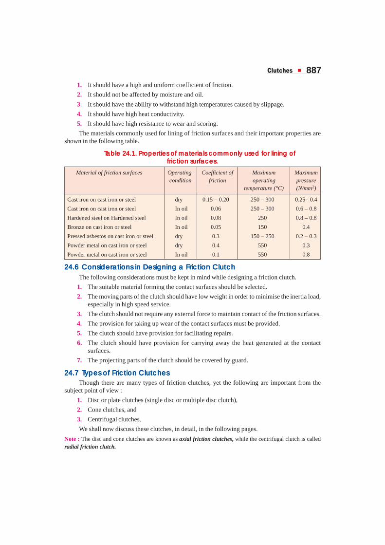
The materials commonly used for lining of friction surfaces and their important properties areshown in the following table.
TTTTTaaaaable 24.1.ble 24.1.ble 24.1.ble 24.1.ble 24.1. Pr Pr Pr Pr Properoperoperoperoperties of maties of maties of maties of maties of materterterterterials commonly used fials commonly used fials commonly used fials commonly used fials commonly used for lining ofor lining ofor lining ofor lining ofor lining offrfrfrfrfriction surfiction surfiction surfiction surfiction surfacesacesacesacesaces.....
Material of friction surfaces Operating Coefficient of Maximum Maximum condition friction operating pressure
temperature (°C) (N/mm2)
Cast iron on cast iron or steel dry 0.15 – 0.20 250 – 300 0.25– 0.4
Cast iron on cast iron or steel In oil 0.06 250 – 300 0.6 – 0.8
Hardened steel on Hardened steel In oil 0.08 250 0.8 – 0.8
Bronze on cast iron or steel In oil 0.05 150 0.4
Pressed asbestos on cast iron or steel dry 0.3 150 – 250 0.2 – 0.3
Powder metal on cast iron or steel dry 0.4 550 0.3
Powder metal on cast iron or steel In oil 0.1 550 0.8
24.624.624.624.624.6 Considerations in Designing a Friction ClutchConsiderations in Designing a Friction ClutchConsiderations in Designing a Friction ClutchConsiderations in Designing a Friction ClutchConsiderations in Designing a Friction ClutchThe following considerations must be kept in mind while designing a friction clutch.
1. The suitable material forming the contact surfaces should be selected.
2. The moving parts of the clutch should have low weight in order to minimise the inertia load,especially in high speed service.
3. The clutch should not require any external force to maintain contact of the friction surfaces.
4. The provision for taking up wear of the contact surfaces must be provided.
5. The clutch should have provision for facilitating repairs.
6. The clutch should have provision for carrying away the heat generated at the contactsurfaces.
7. The projecting parts of the clutch should be covered by guard.
24.724.724.724.724.7 TTTTTypes of Frypes of Frypes of Frypes of Frypes of Friction Clutchesiction Clutchesiction Clutchesiction Clutchesiction ClutchesThough there are many types of friction clutches, yet the following are important from the
subject point of view :
1. Disc or plate clutches (single disc or multiple disc clutch),
2. Cone clutches, and
3. Centrifugal clutches.
We shall now discuss these clutches, in detail, in the following pages.
Note : The disc and cone clutches are known as axial friction clutches, while the centrifugal clutch is calledradial friction clutch.

888 � ���������������������������
24.824.824.824.824.8 Single Disc or Plate ClutchSingle Disc or Plate ClutchSingle Disc or Plate ClutchSingle Disc or Plate ClutchSingle Disc or Plate Clutch
Fig. 24.2. Single disc or plate clutch.
A single disc or plate clutch, as shown in Fig 24.2, consists of a clutch plate whose both sidesare faced with a frictional material (usually of Ferrodo). It is mounted on the hub which is free tomove axially along the splines of the driven shaft. The pressure plate is mounted inside the clutchbody which is bolted to the flywheel. Both the pressure plate and the flywheel rotate with the enginecrankshaft or the driving shaft. The pressure plate pushes the clutch plate towards the flywheel by aset of strong springs which are arranged radially inside the body. The three levers (also known asrelease levers or fingers) are carried on pivots suspended from the case of the body. These arearranged in such a manner so that the pressure plate moves away from the flywheel by the inwardmovement of a thrust bearing. The bearing is mounted upon a forked shaft and moves forward whenthe clutch pedal is pressed.
When the clutch pedal is pressed down, its linkage forces the thrust release bearing to move intowards the flywheel and pressing the longerends of the levers inward. The levers areforced to turn on their suspended pivot andthe pressure plate moves away from theflywheel by the knife edges, therebycompressing the clutch springs. This actionremoves the pressure from the clutch plateand thus moves back from the flywheel andthe driven shaft becomes stationary. On theother hand, when the foot is taken off fromthe clutch pedal, the thrust bearing movesback by the levers. This allows the springsto extend and thus the pressure plate pushesthe clutch plate back towards the flywheel.
When a car hits an object and decelerates quicklyto objects are thrown forward as they continue to
move forwards due to inertia.

�������� � 889
The axial pressure exerted by the spring provides a frictional force in the circumferential directionwhen the relative motion between the driving and driven members tends to take place. If the torquedue to this frictional force exceeds the torque to be transmitted, then no slipping takes place and thepower is transmitted from the driving shaft to the driven shaft.
24.924.924.924.924.9 Design of a Disc or Plate ClutchDesign of a Disc or Plate ClutchDesign of a Disc or Plate ClutchDesign of a Disc or Plate ClutchDesign of a Disc or Plate ClutchConsider two friction surfaces maintained in contact by an axial thrust (W ) as shown in
Fig. 24.3 (a).
Fig. 24.3. Forces on a disc clutch.
Let T = Torque transmitted by the clutch,p = Intensity of axial pressure with which the contact surfaces are
held together,
r1 and r2 = External and internal radii of friction faces,
r = Mean radius of the friction face, and
µ = Coefficient of friction.
Consider an elementary ring of radius r and thickness dr as shown in Fig. 24.3 (b).
We know that area of the contact surface or friction surface
= 2π r.dr
∴ Normal or axial force on the ring,
δW = Pressure × Area = p × 2π r.dr
and the frictional force on the ring acting tangentially at radius r,
Fr = µ × δW = µ.p × 2π r.dr
∴ Frictional torque acting on the ring,
Tr = Fr × r = µ.p × 2π r.dr × r = 2 π µ p. r2.dr
We shall now consider the following two cases :
1. When there is a uniform pressure, and
2. When there is a uniform axial wear.
1. Considering uniform pressure. When the pressure is uniformly distributed over the entirearea of the friction face as shown in Fig. 24.3 (a), then the intensity of pressure,
p =( )2 2
1 2( ) π −
W
r r
890 � ���������������������������
where W = Axial thrust with which the friction surfaces are held together.
We have discussed above that the frictional torque on the elementary ring of radius r andthickness dr is
Tr = 2π µ.p.r2.dr
Integrating this equation within the limits from r2 to r1 for the total friction torque.
∴ Total frictional torque acting on the friction surface or on the clutch,
T =1
1
22
322 . . . 2 .
3
π µ = πµ ∫
rr
rr
rp r dr p
=( )
3 3 3 31 2 1 2
2 21 2
( ) ( ) ( ) ( )2 . 2
3 3[ ( ) ]
− −π µ = π µ × π −
r r r rWp
r r... (Substituting the value of p)
=3 3
1 22 2
1 2
( ) ( )2. . .
3 ( ) ( )
r rW W R
r r
−µ = µ −
where R =3 3
1 22 2
1 2
( ) ( )2
3 ( ) ( )
r r
r r
−
− = Mean radius of the friction surface.
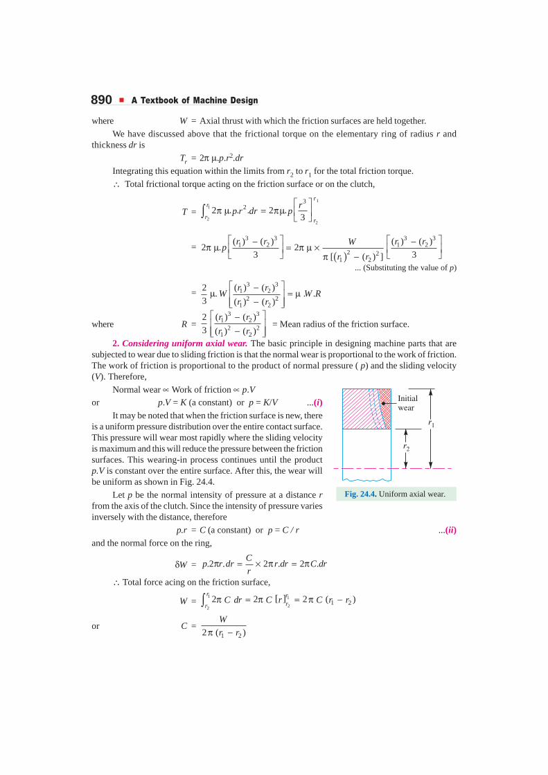
2. Considering uniform axial wear. The basic principle in designing machine parts that aresubjected to wear due to sliding friction is that the normal wear is proportional to the work of friction.The work of friction is proportional to the product of normal pressure ( p) and the sliding velocity(V). Therefore,
Normal wear ∝ Work of friction ∝ p.Vor p.V = K (a constant) or p = K/V ...(i)
It may be noted that when the friction surface is new, thereis a uniform pressure distribution over the entire contact surface.This pressure will wear most rapidly where the sliding velocityis maximum and this will reduce the pressure between the frictionsurfaces. This wearing-in process continues until the productp.V is constant over the entire surface. After this, the wear willbe uniform as shown in Fig. 24.4.
Let p be the normal intensity of pressure at a distance rfrom the axis of the clutch. Since the intensity of pressure variesinversely with the distance, therefore
p.r = C (a constant) or p = C / r ...(ii)and the normal force on the ring,
δW = .2 . 2 . 2 .C
p r dr r dr C drr
π = × π = π
∴ Total force acing on the friction surface,
W = [ ]1 1
221 22 2 2 ( )
r rrr
C dr C r C r rπ = π = π −∫
or C =1 22 ( )
W
r rπ −
Fig. 24.4. Uniform axial wear.
�������� � 891
We know that the frictional torque acting on the ring,
Tr = 2 22 . . . 2 . 2 . . .C
p r dr r dr C r drr
π µ = π µ × × = πµ ...(∵ p = C/r)
∴ Total frictional torque acting on the friction surface (or on the clutch),
T =
11
22
2
2 . . 22
π µ = π µ ∫
rr
r r
rC r dr C
=( ) ( ) ( ) ( )
2 22 21 2
1 22 . . [ ]2
r rC C r r
− πµ = π µ −
= ( ) ( )2 21 2 1 2
1 2
1[ ] . ( ) . .
2 ( ) 2
Wr r W r r W R
r rπµ × − = × µ + = µ
π −
where R = 1 2
2
r r+ = Mean radius of the friction surface.
Notes : 1. In general, total frictional torque acting on the friction surfaces (or on the clutch) is given by
T = n.µ.W.R
where n = Number of pairs of friction (or contact) surfaces, and
R = Mean radius of friction surface
=3 3
1 22 2
1 2
2 ( ) ( )
3 ( ) ( )
r r
r r
− −
... (For uniform pressure)
= 1 2
2
r r+... (For uniform wear)
2. For a single disc or plate clutch, normally both sides of the disc are effective. Therefore a single discclutch has two pairs of surfaces in contact (i.e. n = 2).
3. Since the intensity of pressure is maximum at the inner radius (r2) of the friction or contact surface,therefore equation (ii) may be written as
pmax × r2 = C or pmax = C / r2
4. Since the intensity of pressure is minimum at the outer radius (r1) of the friction or contact surface,therefore equation (ii) may be written as
pmin × r1 = C or pmin = C / r1
5. The average pressure ( pav) on the friction or contact surface is given by
pav =( ) ( )2 2
1 2
Total force on friction surface
Cross-sectional area of friction surface [ ]
W
r r=
π −6. In case of a new clutch, the intensity of pressure is approximately uniform, but in an old clutch, the
uniform wear theory is more approximate.
7. The uniform pressure theory gives a higher friction torquethan the uniform wear theory. Therefore in case of friction clutches,uniform wear should be considered, unless otherwise stated.
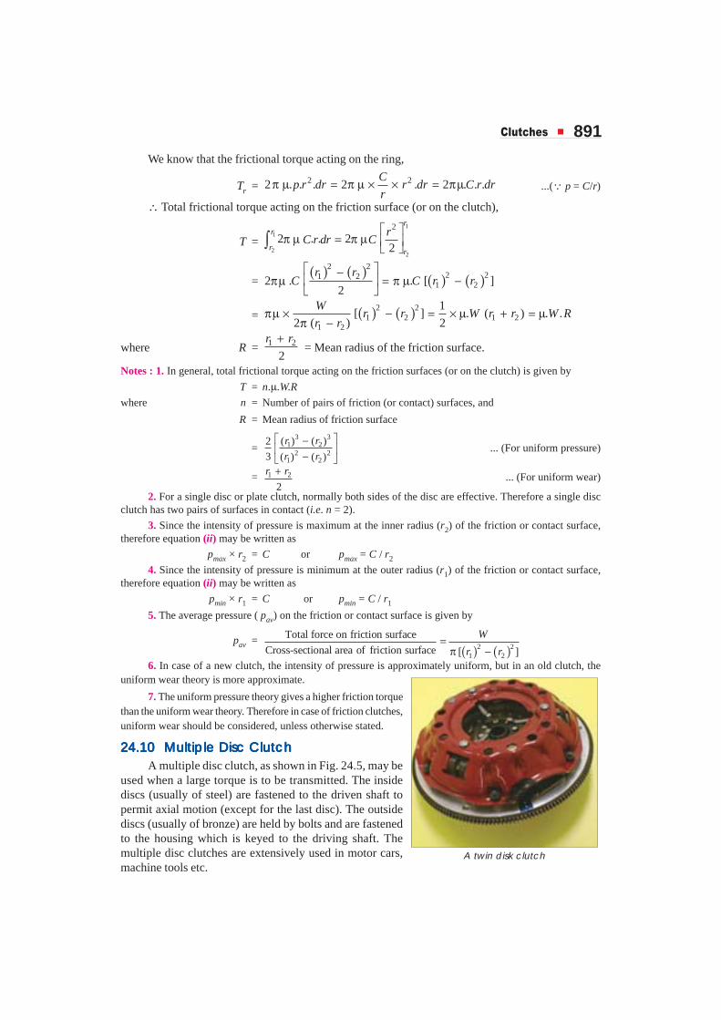
24.1024.1024.1024.1024.10 Multiple Disc ClutchMultiple Disc ClutchMultiple Disc ClutchMultiple Disc ClutchMultiple Disc ClutchA multiple disc clutch, as shown in Fig. 24.5, may be
used when a large torque is to be transmitted. The insidediscs (usually of steel) are fastened to the driven shaft topermit axial motion (except for the last disc). The outsidediscs (usually of bronze) are held by bolts and are fastenedto the housing which is keyed to the driving shaft. Themultiple disc clutches are extensively used in motor cars,machine tools etc.
A twin disk clutch

892 � ���������������������������
Fig. 24.5. Multiple disc clutch.
Let n1 = Number of discs on the driving shaft, andn2 = Number of discs on the driven shaft.
∴ Number of pairs of contact surfaces,n = n1 + n2 – 1
and total frictional torque acting on the friction surfaces or on the clutch,T = n.µ.W.R
where R = Mean radius of friction surfaces
=( )( ) ( )
3 31 2
2 21 2
( )2
3
r r
r r
− −
... (For uniform pressure)
= 1 2
2
r r+... (For uniform wear)
Example 24.1. Determine the maximum, minimum and average pressure in a plate clutchwhen the axial force is 4 kN. The inside radius of the contact surface is 50 mm and the outside radiusis 100 mm. Assume uniform wear.
Solution. Given : W = 4 kN = 4000 N ; r2 = 50 mm ; r1 = 100 mmMaximum pressure
Let pmax = Maximum pressure.
Since the intensity of pressure is maximum at the inner radius (r2), therefore
pmax × r2 = C or C = 50 pmax
We also know that total force on the contact surface (W ),
4000 = 2πC (r1 – r2) = 2π × 50 pmax (100 – 50) = 15 710 pmax
∴ pmax = 4000 / 15 710 = 0.2546 N/mm2 Ans.Minimum pressure
Let pmin = Minimum pressure.
Since the intensity of pressure is minimum at the outer radius (r1 ), therefore,
pmin × r1 = C or C = 100 pmin

�������� � 893
We know that the total force on the contact surface (W ),
4000 = 2πC (r1 – r2) = 2π × 100 pmin (100 – 50) = 31 420 pmin
∴ pmin = 4000 / 31 420 = 0.1273 N/mm2 Ans.Average pressure
We know that average pressure,
pav = 2 21 2
Total normal force on contact surface
Cross-sectional area of contact surface [( ) ( ) ]=
π −W
r r
=( )
22 2
40000.17 N/mm
[ 100 (50) ]=
π − Ans.
Example 24.2. A plate clutch having a single driving plate with contact surfaces on each sideis required to transmit 110 kW at 1250 r.p.m. The outer diameter of the contact surfaces is to be300 mm. The coefficient of friction is 0.4.
(a) Assuming a uniform pressure of 0.17 N/mm2; determine the inner diameter of the frictionsurfaces.
(b) Assuming the same dimensions and the same total axial thrust, determine the maximumtorque that can be transmitted and the maximum intensity of pressure when uniform wearconditions have been reached.
Solution. Given : P = 110 kW = 110 × 103W ; N = 1250 r.p.m. ; d1 = 300 mm or r1 = 150 mm ;µ = 0.4 ; p = 0.17 N/mm2
(a) Inner diameter of the friction surfacesLet d2 = Inner diameter of the contact or friction surfaces, and
r2 = Inner radius of the contact or friction surfaces.
We know that the torque transmitted by the clutch,
T =360 110 10 60
840 N-m2 2 1250
× × ×= =π π ×
P
N= 840 × 103 N-mm
Axial thrust with which the contact surfaces are held together,
W = Pressure × Area = p × π [(r1)2 – (r2)2]
= 0.17 × π [(150)2 – (r2)2] = 0.534 [(150)2 – (r2)2] ...(i)and mean radius of the contact surface for uniform pressure conditions,
R =2
3
3 3 3 31 2 2
2 2 2 21 2 2
( ) ( ) (150) ( )2
3( ) ( ) (150) ( )
− −= − −
r r r
r r r
∴ Torque transmitted by the clutch ( T ),
840 × 103 = n.µ.W.R
=3 3
2 2 22 2 2
2
(150) – ( )22 0.4 0.534 [(150) – ( ) ]
3 (150) – ( )
rr
r
× × ×
...(∵ n = 2)
= 0.285 [(150)3 – (r2)3]
or (150)3 – (r2)3 = 840 × 103 / 0.285 = 2.95 × 10⁶
∴ (r2)3 = (150)3 – 2.95 × 106 = 0.425 × 10⁶ or r2 = 75 mm
and d2 = 2r2 = 2 × 75 = 150 mm Ans.

894 � ���������������������������
(b) Maximum torque transmitted
We know that the axial thrust,
W = 0.534 [(150)2 – (r2)2] ... [From equation (i)]
= 0.534 [(150)2 – (75)2] = 9011 N
and mean radius of the contact surfaces for uniform wear conditions,
R = 1 2 150 75112.5 mm
2 2
r r+ += =
∴ Maximum torque transmitted,
T = n.µ.W.R = 2 × 0.4 × 9011 × 112.5 = 811 × 103 N-mm
= 811 N-m Ans.Maximum intensity of pressure
For uniform wear conditions, p.r = C (a constant). Since the intensity of pressure is maximum atthe inner radius (r2), therefore
pmax × r2 = C or C = pmax × 75 N/mm
We know that the axial thrust ( W ),
9011 = 2 π C (r1 – r2) = 2π × pmax × 75 (150 – 75) = 35 347 pmax
∴ pmax = 9011 / 35 347 = 0.255 N/mm2 Ans.
Example 24.3. A single plate clutch, effective on both sides, is required to transmit 25 kW at3000 r.p.m. Determine the outer and inner diameters of frictional surface if the coefficient of frictionis 0.255, ratio of diameters is 1.25 and the maximum pressure is not to exceed 0.1 N/mm2. Also,determine the axial thrust to be provided by springs. Assume the theory of uniform wear.
Solution. Given : n = 2 ; P = 25 kW = 25 × 103 W ; N = 3000 r.p.m. ; µ = 0.255 ;d1 / d2 = 1.25 or r1 / r2 = 1.25 ; pmax = 0.1 N/mm2
Outer and inner diameters of frictional surface
Let d1 and d2 = Outer and inner diameters (in mm) of frictional surface, and
r1 and r2 = Corresponding radii (in mm) of frictional surface.
We know that the torque transmitted by the clutch,
T =360 25 10 60
79.6 N-m 79 600 N-mm2 2 3000
× × ×= = =π π ×
P
N
For uniform wear conditions, p.r = C (a constant). Since the intensity of pressure is maximum atthe inner radius (r2), therefore.
pmax × r2 = C
or C = 0.1 r2 N/mm
and normal or axial load acting on the friction surface,
W = 2π C (r1 – r2) = 2π × 0.1 r2 (1.25 r2 – r2)
= 0.157 (r2)2 ... (∵ r1 / r2 = 1.25)
We know that mean radius of the frictional surface (for uniform wear),
R = 1 2 2 22
1.251.125
2 2
+ += =r r r rr
and the torque transmitted (T ),
79 600 = n.µ.W.R = 2 × 0.255 × 0.157 (r2)2 1.125 r2 = 0.09 (r2)3
∴ (r2)3 = 79.6 × 10³ / 0.09 = 884 × 103 or r2 = 96 mm
and r1 = 1.25 r2 = 1.25 × 96 = 120 mm

�������� � 895
∴ Outer diameter of frictional surface,
d1 = 2r1 = 2 × 120 = 240 mm Ans.and inner diameter of frictional surface,
d2 = 2r2 = 2 × 96 = 192 mm Ans.Axial thrust to be provided by springs
We know that axial thrust to be provided by springs,W = 2π C (r1 – r2) = 2π × 0.1 r2 (1.25 r2 – r2)
= 0.157 (r2)2 = 0.157 (96)2 = 1447 N Ans.Example 24.4. A dry single plate clutch is to be designed for an automotive vehicle whose
engine is rated to give 100 kW at 2400 r.p.m. and maximum torque 500 N-m. The outer radius of thefriction plate is 25% more than the inner radius. The intensity of pressure between the plate is not toexceed 0.07 N/mm2. The coefficient of friction may be assumed equal to 0.3. The helical springsrequired by this clutch to provide axial force necessary to engage the clutch are eight. If each springhas stiffness equal to 40 N/mm, determine the dimensions of the friction plate and initial compres-sion in the springs.
Solution. Given : P = 100 kW = 100 × 103 W ; *N = 2400 r.p.m. ; T = 500 N-m= 500 × 103 N-mm ; p = 0.07 N/mm2 ; µ = 0.3 ; No. of springs = 8 ; Stiffness/spring = 40 N/mmDimensions of the friction plate
Let r1 = Outer radius of the friction plate, andr2 = Inner radius of the friction plate.
Since the outer radius of the friction plate is 25% more than the inner radius, thereforer1 = 1.25 r2
For uniform wear conditions, p.r = C (a constant). Since the intensity of pressure is maximum atthe inner radius (r2), therefore
p.r2 = C or C = 0.07 r2 N/mm
and axial load acting on the friction plate,
W = 2π C (r1 – r2) = 2π × 0.07 r2 (1.25 r2 – r2) = 0.11 (r2)2 N ...(i)
We know that mean radius of the friction plate, for uniform wear,
R = 1 2 2 22
1.251.125
2 2
+ += =r r r rr
∴ Torque transmitted (T ),
500 × 103 = n.µ.W.R = 2 × 0.3 × 0.11 (r2)2 1.125 r2 = 0.074 (r2)3 ...(∵ n = 2)
(r2)3 = 500 × 103 / 0.074 = 6757 × 103 or r2 = 190 mm Ans.and r1 = 1.25 r2 = 1.25 × 190 = 237.5 mm Ans.Initial compression in the springs
We know that total stiffness of the springs,s = Stiffness per spring × No. of springs = 40 × 8 = 320 N/mm
Axial force required to engage the clutch,W = 0.11 (r2)
2 = 0.11 (190)2 = 3970 N ... [From equation (i)]
∴ Initial compression in the springs= W / s = 3970 / 320 = 12.4 mm Ans.
* Superfluous data

896 � ���������������������������
Example 24.5. A single dry plate clutch is to be designed to transmit 7.5 kW at 900 r.p.m. Find :
1. Diameter of the shaft,
2. Mean radius and face width of the friction lining assuming the ratio of the mean radius tothe face width as 4,
3. Outer and inner radii of the clutch plate, and
4. Dimensions of the spring, assuming that the number of springs are 6 and spring index = 6.The allowable shear stress for the spring wire may be taken as 420 MPa.
Solution. Given : P = 7.5 kW = 7500 W ; N = 900 r.p.m. ; r/b = 4 ; No. of springs = 6 ;C = D/d = 6 ; τ = 420 MPa = 420 N/mm2
1. Diameter of the shaftLet ds = Diameter of the shaft, and
τ1 = Shear stress for the shaft material. It may be assumed as 40 N/mm2.We know that the torque transmitted,
T =60 7500 60
79.6 N-m 79 600 N-mm2 2 900
P
N
× ×= = =π π × ...(i)
We also know that the torque transmitted (T),
79 600 = 3 3 3
1 ( ) 40 ( ) 7.855 ( )16 16
π π× τ = × =s s sd d d
∴ (ds)3 = 79 600 / 7.855 = 10 134 or ds = 21.6 say 25 mm Ans.
2. Mean radius and face width of the friction liningLet R = Mean radius of the friction lining, and
b = Face width of the friction lining = R/4 ... (Given)
We know that the area of the friction faces,A = 2π R.b
∴ Normal or the axial force acting on the friction faces,W = A × p = 2π R.b.p
In car cooling system a pump circulates water through the engine and through the pipesof the radiator.
Engine
Radiator
Airflow
Fins
Circulating
water

�������� � 897
and torque transmitted, T = µ W.R.n = µ (2π Rb.p) R.n
=32 . . . .
4 2
π µ π × × = × µ R
R p R n R p n ...(ii)
Assuming the intensity of pressure (p) as 0.07 N/mm2 and coefficient of friction ( µ) as 0.25, wehave from equations (i) and (ii),
79 600 = 3 30.25 0.07 2 0.0552
π × × × × =R R
... (∵ n = 2, for both sides of plate effective)
∴ R 3 = 79 600 / 0.055 = 1.45 × 10⁶ or R = 113.2 say 114 mm Ans.and b = R / 4 = 114 / 4 = 28.5 mm Ans.3. Outer and inner radii of the clutch plate
Let r1 and r2 = Outer and inner radii of the clutch plate respectively.
Since the face width (or radial width) of the plate is equal to the difference of the outer and innerradii, therefore,
b = r1 – r2 or r1 – r2 = 28.5 mm ...(iii)We know that for uniform wear, mean radius of the clutch plate,
R = 1 21 2or 2 2 114 228 mm
2
++ = = × =
r rr r R ...(iv)
From equations (iii), and (iv), we find that
r1 = 128.25 mm and r2 = 99.75 mm Ans.4. Dimensions of the spring
Let D = Mean diameter of the spring, and
d = Diameter of the spring wire.We know that the axial force on the friction faces,
W = 2π R.b.p = 2π × 114 × 28.5 × 0.07 = 1429.2 N
In order to allow for adjustment and for maximum engine torque, the spring is designed for anoverload of 25%.
∴ Total load on the springs
= 1.25 W = 1.25 × 1429.2 = 1786.5 N
Since there are 6 springs, therefore maximum load on each spring,
Ws = 1786.5 / 6 = 297.75 N
We know that Wahl's stress factor,
K =4 1 0.615 4 6 1 0.615
1.25254 4 4 6 4 6
− × −+ = + =− × −
C
C CWe also know that maximum shear stress induced in the wire (τ),
420 = 2 2 2
8 8 297.75 6 56971.2525sW C
Kd d d
× ×× = × =π π
∴ d 2 = 5697 / 420 = 13.56 or d = 3.68 mm
We shall take a standard wire of size SWG 8 having diameter (d) = 4.064 mm Ans.and mean diameter of the spring,
D = C.d = 6 × 4.064 = 24.384 say 24.4 mm Ans.

898 � ���������������������������
Let us assume that the spring has 4 active turns (i.e. n = 4). Therefore compression of the spring,
δ = 3 3
3
8 . . 8 297.75 6 46.03 mm
. 84 10 4.064
× × ×= =× ×
sW C n
G d... (Taking G = 84 × 103 N/mm2)
Assuming squared and ground ends, total number of turns,
n' = n + 2 = 4 + 2 = 6
We know that free length of the spring,
LF = n'.d + δ + 0.15 δ= 6 × 4.064 + 6.03 + 0.15 × 6.03 = 31.32 mm Ans.
and pitch of the coils = F 31.326.264 mm
1 6 1= =
′ − −L
n Ans.
Example 24.6. Design a single plate automobile clutch to transmit a maximum torque of 250N-m at 2000 r.p.m. The outside diameter of the clutch is 250 mm and the clutch is engaged at 55 km/h.Find : 1. the number of revolutions of the clutch slip during engagement; and 2. heat to be dissipatedby the clutch for each engagement.
The following additional data is available:
Engine torque during engagement = 100 N-m; Mass of the automobile = 1500 kg; Diameter ofthe automobile wheel = 0.7 m; Moment of inertia of combined engine rotating parts, flywheel andinput side of the clutch = 1 kg-m2; Gear reduction ratio at differential = 5; Torque at rear wheelsavailable for accelerating automobile = 175 N-m; Coefficient of friction for the clutch material= 0.3; Permissible pressure = 0.13 N/mm2.
Solution. Given : T = 250 N-m = 250 × 103 N-mm ; N = 2000 r.p.m. ; d1 = 250 mm orr1 = 125 mm ; V = 55 km/h = 15.3 m/s ; Te = 100 N-m ; m = 1500 kg ; Dw = 0.7 m or Rw = 0.35 m ;I = 1 kg-m2 ; Ta = 175 N-m ; Gear ratio = 5 ; µ = 0.3 ; p = 0.13 N/mm2
1. Number of revolutions of the clutch slip during engagementFirst of all, let us find the inside radius of the clutch (r2). We know that, for uniform wear, mean
radius of the clutch,
R = 1 2 22
12562.5 0.5
2 2
+ += = +
r r rr
and axial force on the clutch,
W = p.π [(r1)2 – (r2)2] = 0.13 × π [(125)2 – (r2)
2]
We know that the torque transmitted (T ),
250 × 103 = n.µ.W.R = 2 × 0.3 × 0.13 π [(125)2 – (r2)2] [62.5 + 0.5 r2]
= 0.245 [ 976.56 × 10³ + 7812.5 r2 – 62.5 (r2)2 – 0.5 (r2)
3]
Solving by hit and trial, we find that
r2 = 70 mm
We know that angular velocity of the engine,ωe = 2πN / 60 = 2π × 2000 / 60 = 210 rad / s
and angular velocity of the wheel,
ωW = Velocity of wheel 15.3
43.7 rad / sRadiusof wheel 0.35
= = =w
V
RSince the gear ratio is 5, therefore angular velocity of the clutch follower shaft,
ω0 = ωW × 5 = 43.7 × 5 = 218.5 rad / s

�������� � 899
We know that angular acceleration of the engine during the clutch slip period of the clutch,
αe = 2100 250150 rad / s
1
− −= = −eT T
ILet a = Linear acceleration of the automobile.
We know that accelerating force on the automobile,
Fa =175
500 N0.35
= =aT
RWe also know that accelerating force (Fa),
500 = m.a = 1500 × a or a = 500 / 1500 = 0.33 m/s2
∴ Angular acceleration of the clutch output,
α0 = 2Acceleration × Gear ratio 0.33 54.7 rad/s
Radius of wheel 0.35
×= =
We know that clutch slip period,
∆t = 0
0
218 2100.055 s
4.7 ( 150)
ω − ω −= =α − α − −
e
e
Angle through which the input side of the clutch rotates during engagement time (∆t) is
θe = 21( )
2ω × ∆ + α ∆e et t
= 210 × 0.055 + 1
2 (– 150) (0.055)2 = 11.32 rad
and angle through which the output side of the clutch rotates during engagement time (∆t) is
θ0 = ω0 × ∆t + 1
2 α0 (∆t)2
= 218.5 × 0.055 + 1
2 × 4.7 (0.055)2 = 12 rad
∴ Angle of clutch slip,
θ = θ0 – θe = 12 – 11.32 = 0.68 rad
We know that number of revolutions of the clutch slip during engagement
=0.68
0.11 revolutions2 2
θ = =π π Ans.
Heat to be dissipated by the clutch for each engagementWe know that heat to be dissipated by the clutch for each engagement
= T.θ = 250 × 0.68 = 170 J Ans.Example 24.7. A multiple disc clutch has five plates having four pairs of active friction
surfaces. If the intensity of pressure is not to exceed 0.127 N/mm2,find the power transmitted at 500 r.p.m. The outer and inner radiiof friction surfaces are 125 mm and 75 mm respectively. Assumeuniform wear and take coefficient of friction = 0.3.
Solution. Given : n1 + n2 = 5 ; n = 4 ; p = 0.127 N/mm2 ;N = 500 r.p.m. ; r1 = 125 mm ; r2 = 75 mm ; µ = 0.3
We know that for uniform wear, p.r = C (a constant). Sincethe intensity of pressure is maximum at the inner radius (r2),therefore,
p.r2 = C or C = 0.127 × 75 = 9.525 N/mmA twin-disk clutch

900 � ���������������������������
and axial force required to engage the clutch,
W = 2πC (r1 – r2) = 2π × 9.525 (125 – 75) = 2993 NMean radius of the friction surfaces,
R = 1 2 125 75100 mm 0.1 m
2 2
+ += = =r r
We know that the torque transmitted,T = n.µ.W.R = 4 × 0.3 × 2993 × 0.1 = 359 N-m
∴ Power transmitted, P =2 359 2 500
18 800 W60 60
× π × π ×= =T N= 18.8 kW Ans.
Example 24.8. A multi-disc clutch has three discs on the driving shaft and two on the drivenshaft. The inside diameter of the contact surface is 120 mm. The maximum pressure between thesurface is limited to 0.1 N/mm2. Design the clutch for transmitting 25 kW at 1575 r.p.m. Assumeuniform wear condition and coefficient of friction as 0.3.
Solution. Given : n1 = 3 ; n2 = 2 ; d2 = 120 mm or r2 = 60 mm ; pmax = 0.1 N/mm2 ; P = 25 kW= 25 × 103 W ; N = 1575 r.p.m. ; µ = 0.3
Let r1 = Outside radius of the contact surface.
We know that the torque transmitted,
T =360 25 10 60
151.6 N-m 151 600 N-mm2 2 1575
× × ×= = =π π ×
P
NFor uniform wear, we know that p.r = C. Since the intensity of pressure is maximum at the inner
radius (r2), therefore,
pmax × r2 = C or C = 0.1 × 60 = 6 N/mm
We know that the axial force on each friction surface,
W = 2πC (r1 – r2) = 2π × 6(r1 – 60) = 37.7 (r1 – 60) ...(i)For uniform wear, mean radius of the contact surface,
R = 1 2 11
600.5 30
2 2
+ += = +
r r rr
We know that number of pairs of contact surfaces,
n = n1 + n2 – 1 = 3 + 2 – 1 = 4
∴ Torque transmitted (T),
151 600 = n.µ.W.R = 4 × 0.3 × 37.7 (r1 – 60) (0.5 r1 + 30)
... [Substituting the value of W from equation (i)]
= 22.62 (r1)2 – 81 432
∴ (r1)2 =151 600 81 432
10 30222.62
+ =
or r1 = 101.5 mm Ans.Example 24.9. A multiple disc clutch, steel on bronze, is to transmit 4.5 kW at 750 r.p.m. The
inner radius of the contact is 40 mm and outer radius of the contact is 70 mm. The clutch operates inoil with an expected coefficient of 0.1. The average allowable pressure is 0.35 N/mm2. Find : 1. thetotal number of steel and bronze discs; 2. the actual axial force required; 3. the actual averagepressure; and 4. the actual maximum pressure.
Solution. Given : P = 4.5 kW = 4500 W ; N = 750 r.p.m. ; r2 = 40 mm ; r1 = 70 mm ; µ = 0.1 ;pav = 0.35 N/mm2
�������� � 901
1. Total number of steel and bronze discsLet n = Number of pairs of contact surfaces.
We know that the torque transmitted by the clutch,
T =60 4500 60
57.3 N-m 57 300 N-mm2 2 750
× ×= = =π π ×
P
N
For uniform wear, mean radius of the contact surfaces,
R = 1 2 70 4055 mm
2 2
+ += =r r
and average axial force required,
W = pav × π [(r1)2 – (r2)2] = 0.35 × π [(70)2 – (40)2] = 3630 N
We also know that the torque transmitted (T ),
57 300 = n.µ.W.R = n × 0.1 × 3630 × 55 = 19 965 n
∴ n = 57 300 / 19 965 = 2.87
Since the number of pairs of contact surfaces must be even, therefore we shall use 4 pairs ofcontact surfaces with 3 steel discs and 2 bronze discs (because the number of pairs of contact surfacesis one less than the total number of discs). Ans.2. Actual axial force required
Let W ' = Actual axial force required.
Since the actual number of pairs of contact surfaces is 4, therefore actual torque developed bythe clutch for one pair of contact surface,
T ' = 57 300
14 325 N-mm4
= =T
n
We know that torque developed for one pair of contact surface (T '),
14 325 = µ.W '.R = 0.1 × W ' × 55 = 5.5 W '
∴ W ' = 14 325 / 5.5 = 2604.5 N Ans.
3. Actual average pressure
We know that the actual average pressure,
p'av = ( ) ( ) ( ) ( )2
2 2 2 21 2
2604.50.25 N/mm
[ ] [ 70 40 ]
′= =
π − π −
W
r r Ans.
4. Actual maximum pressure
Let pmax = Actual maximum pressure.
For uniform wear, p.r = C. Since the intensity of pressure is maximum at the inner radius,therefore,
pmax × r2 = C or C = 40 pmax N/mm
We know that the actual axial force (W '),
2604.5 = 2πC (r1 – r2) = 2π × 40 pmax ( 70 – 40) = 7541 pmax
∴ pmax = 2604.5 / 7541 = 0.345 N/mm2 Ans.
Example 24.10. A plate clutch has three discs on the driving shaft and two discs on the drivenshaft, providing four pairs of contact surfaces. The outside diameter of the contact surfaces is240 mm and inside diameter 120 mm. Assuming uniform pressure and µ = 0.3, find the totalspring load pressing the plates together to transmit 25 kW at 1575 r.p.m.

902 � ���������������������������
If there are 6 springs each of stiffness 13 kN/m and each of the contact surfaces has worn awayby 1.25 mm, find the maximum power that can be transmitted, assuming uniform wear.
Solution. Given : n1 = 3 ; n2 = 2 ; n = 4 ; d1 = 240 mm or r1 = 120 mm ; d2 = 120 mm orr2 = 60 mm ; µ = 0.3 ; P = 25 kW = 25 × 103 W ; N = 1575 r.p.m.
Total spring loadLet W = Total spring load.
We know that the torque transmitted,
T = 360 25 10 60
151.5 N-m2 2 1575
× × ×= =π π ×
P
N= 151.5 × 10³ N-mm
Mean radius of the contact surface, for uniform pressure,
R =( ) ( )( ) ( )
( )( )
3 3 3 31 2
2 2 2 21 2
2 2 120 (60)93.3 mm
3 3 120 (60)
− − = = − −
r r
r rand torque transmitted (T ),
151.5 × 103 = n.µ.W.R = 4 × 0.3 × W × 93.3 = 112 W
∴ W = 151.5 × 10³ / 112 = 1353 N Ans.Maximum power transmitted
Given : No. of springs = 6
∴ Contact surfaces of the spring = 8
Wear on each contact surface = 1.25 mm
∴ Total wear = 8 × 1.25 = 10 mm = 0.01 m
Stiffness of each spring = 13 kN/m = 13 × 103 N/m
∴ Reduction in spring force
= Total wear × Stiffness per spring × No. of springs
= 0.01 × 13 × 103 × 6 = 780 N
and new axial load, W = 1353 – 780 = 573 N
We know that mean radius of the contact surfaces for uniform wear,
R = 1 2 120 6090 mm 0.09 m
2 2
+ += = =r r
and torque transmitted, T = n . µ W . R = 4 × 0.3 × 573 × 0.09 = 62 N-m
∴ Power transmitted, P =2 62 2 1575
10 227 W 10.227 kW60 60
× π × π ×= = =T N Ans.
24.1124.1124.1124.1124.11 Cone ClutchCone ClutchCone ClutchCone ClutchCone ClutchA cone clutch, as shown in Fig. 24.6, was extensively used in automobiles, but now-a-days it
has been replaced completely by the disc clutch. It consists of one pair of friction surface only. In acone clutch, the driver is keyed to the driving shaft by a sunk key and has an inside conical surface orface which exactly fits into the outside conical surface of the driven. The driven member resting onthe feather key in the driven shaft, may be shifted along the shaft by a forked lever provided at B, inorder to engage the clutch by bringing the two conical surfaces in contact. Due to the frictionalresistance set up at this contact surface, the torque is transmitted from one shaft to another. In somecases, a spring is placed around the driven shaft in contact with the hub of the driven. This spring

�������� � 903
holds the clutch faces in contact and maintains the pressure between them, and the forked lever isused only for disengagement of the clutch. The contact surfaces of the clutch may be metal to metalcontact, but more often the driven member is lined with some material like wood, leather, cork orasbestos etc. The material of the clutch faces (i.e. contact surfaces) depends upon the allowablenormal pressure and the coefficient of friction.
Fig. 24.6. Cone clutch.
24.1224.1224.1224.1224.12 Design of a Cone ClutchDesign of a Cone ClutchDesign of a Cone ClutchDesign of a Cone ClutchDesign of a Cone ClutchConsider a pair of friction surfaces of a cone clutch as shown in Fig. 24.7. A little consideration
will show that the area of contact of a pair of friction surface is a frustrum of a cone.
Fig. 24.7. Friction surfaces as a frustrum of a cone.
Let pn = Intensity of pressure with which the conical friction surfaces are heldtogether (i.e. normal pressure between the contact surfaces),
r1 = Outer radius of friction surface,r2 = Inner radius of friction surface,
R = Mean radius of friction surface = 1 2 ,2
r r+
α = Semi-angle of the cone (also called face angle of the cone) or angle ofthe friction surface with the axis of the clutch,
µ = Coefficient of friction between the contact surfaces, and
b = Width of the friction surfaces (also known as face width or cone face).

904 � ���������������������������
Consider a small ring of radius r and thickness dr as shown in Fig. 24.7. Let dl is the length ofring of the friction surface, such that,
dl = dr cosec α∴ Area of ring = 2π r. dl = 2π r.dr cosec αWe shall now consider the following two cases :1. When there is a uniform pressure, and2. When there is a uniform wear.
1. Considering uniform pressureWe know that the normal force acting on the ring,
δWn = Normal pressure × Area of ring = pn × 2π r.dr cosec αand the axial force acting on the ring,
δW = Horizontal component of δWn (i.e. in the direction of W)= δWn × sin α = pn × 2π r.dr cosec α × sin α = 2π × pn.r.dr
∴ Total axial load transmitted to the clutch or the axial spring force required,
W =
11
22
2 221 2( ) ( )
2 . . 2 22 2
rr
n n nr r
r rrp r dr p p
−π × = π = π ∫= π pn [(r1)
2 – (r2)2]
and pn =( )2 2
1 2( )
W
r r π − ...(i)
We know that frictional force on the ring acting tangentially at radius r,Fr = µ.δWn = µ.pn × 2πr.dr cosec α
∴ Frictional torque acting on the ring,
Tr = Fr × r = µ.pn × 2πr.dr cosec α × r
= 2π µ.pn cosec α.r2 dr
Integrating this expression within the limits from r2 to r1 for the total frictional torque on theclutch.
∴ Total frictional torque,
T =
11
22
322 . . cosec . 2 . cosec
3
rr
n nrr
rp r dr p
πµ α = π µ α ∫
=3 3
1 2( ) ( )2 . cosec
3
−π µ α
nr r
p

�������� � 905
Substituting the value of pn from equation (i), we get
T = ( ) ( )( ) ( )3 3
1 22 2
1 2
2 cosec3[ ]
r rW
r r
− π µ × × α π −
= 3 3
1 22 2
1 2
( ) ( )2. cosec
3 ( ) ( )
−× µ α −
r rW
r r...(ii)
Fig. 24.8. Forces on a friction surface.
2. Considering uniform wearIn Fig. 24.7, let pr be the normal intensity of pressure at a distance r from the axis of the clutch.
We know that, in case of uniform wear, the intensity of pressure varies inversely with the distance.
∴ pr.r = C (a constant) or pr = C / r
We know that the normal force acting on the ring,
δWn = Normal pressure × Area of ring = pr × 2πr.dr cosec αand the axial force acting on the ring,
δW = δWn × sin α = pr × 2π r.dr cosec α × sin α= 2p × pr.r dr
= 2 . 2 .C
r dr C drr
π × × = π ... = ∵ r
Cp
r
∴ Total axial load transmitted to the clutch,
W = [ ]1 1
221 22 . 2 2 ( )π = π = π −∫
r rrr
C dr C r C r r
or C =1 22 ( )
W
r rπ −... (iii)
We know that frictional force on the ring acting tangentially at radius r,
Fr = µ.δWn = µ.pr × 2π r.dr cosec α

906 � ���������������������������
∴ Frictional torque acting on the ring,Tr = Fr × r = µ.pr × 2π r.dr cosec α × r
= µ × C
r × 2π r.dr cosec α × r = 2π µ.C cosec α × r dr
Integrating this expression within the limits from r2 to r1 for the total frictional torque on theclutch.
∴ Total frictional torque,
T =
11
22
2
2 . cosec 2 . cosec2
π µ α × = πµ α ∫
rr
r r
rC r dr C
=2 2
1 2( ) ( )2 . cosec
2
r rC
−π µ α
Substituting the value of C from equation (iii), we have
T =2 2
1 2
1 2
( ) ( )2 cosec
2 ( ) 2
r rW
r r
−πµ × × α π −
=1 2. cosec cosec
2
r rW WR
+ µ α = µ α ...(iv)
where R = 1 2
2
r r+ = Mean radius of friction surface.
Since the normal force acting on the friction surface, Wn = W cosec α, therefore the equation(iv) may be written as
T = µ Wn R ...(v)The forces on a friction surface, for steady operation of the clutch and after the clutch is
engaged, is shown in Fig. 24.8 (a) and (b) respectively.
A mammoth caterpillar dump truck for use in quarries and open-cast mines.
�������� � 907
From Fig. 24.8 (a), we find that
r1 – r2 = b sin α and 1 2
2
+=
r rR or r1 + r2 = 2R
∴ From equation (i), normal pressure acting on the friction surface,
pn = 2 21 2 1 21 2 ( ) ( ) 2 . sin[( ) ( ) ]
= =π + − π απ −
W W W
r r r r R br r
or W = pn × 2π R.b sin α = Wn sin αwhere Wn = Normal load acting on the friction surface = pn × 2πR.b
Now the equation (iv) may be written asT = µ ( pn × 2π R. b sin α) R cosec α = 2π µ.pn R2.b
The following points may be noted for a cone clutch :1. The above equations are valid for steady operation of the clutch and after the clutch is
engaged.2. If the clutch is engaged when one member is stationary and the other rotating (i.e. during
engagement of the clutch) as shown in Fig. 24.8 (b), then the cone faces will tend to slide on eachother due to the presence of relative motion. Thus an additional force (of magnitude µ.Wn cos α) actson the clutch which resists the engagement, and the axial force required for engaging the clutchincreases.
∴ Axial force required for engaging the clutch,We = W + µ.Wn cos α = Wn. sin α + µ Wn cos α
= Wn (sin α + µ cos α)It has been found experimentally that the term (µ Wn.cos α) is only 25 percent effective.∴ We = Wn sin α + 0.25 µ Wn cos α = Wn (sin α + 0.25 µ cos α)3. Under steady operation of the clutch, a decrease in the semi-cone angle (α) increases the
torque produced by the clutch (T ) and reduces the axial force (W ). During engaging period, the axialforce required for engaging the clutch (We ) increases under the influence of friction as the angle αdecreases. The value of α can not be decreased much because smaller semi-cone angle (α) requireslarger axial force for its disengagement.
If the clutch is to be designed for free disengagement, the value of tan α must be greater than µ.In case the value of tan α is less than µ, the clutch will not disengage itself and axial force required todisengage the clutch is given by
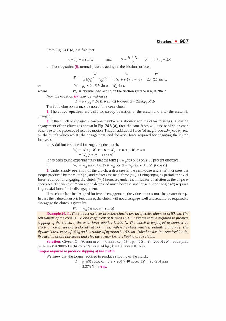
Wd = Wn ( µ cos α – sin α)Example 24.11. The contact surfaces in a cone clutch have an effective diameter of 80 mm. The
semi-angle of the cone is 15° and coefficient of friction is 0.3. Find the torque required to produceslipping of the clutch, if the axial force applied is 200 N. The clutch is employed to connect anelectric motor, running uniformly at 900 r.p.m. with a flywheel which is initially stationary. Theflywheel has a mass of 14 kg and its radius of gyration is 160 mm. Calculate the time required for theflywheel to attain full-speed and also the energy lost in slipping of the clutch.
Solution. Given : D = 80 mm or R = 40 mm ; α = 15° ; µ = 0.3 ; W = 200 N ; N = 900 r.p.m.or ω = 2π × 900/60 = 94.26 rad/s ; m = 14 kg ; k = 160 mm = 0.16 mTorque required to produce slipping of the clutch
We know that the torque required to produce slipping of the clutch,T = µ WR cosec α = 0.3 × 200 × 40 cosec 15° = 9273 N-mm
= 9.273 N-m Ans.

908 � ���������������������������
Time required for the flywheel to attain full-speedLet t = Time required for the flywheel to attain full speed from the stationary
position, and
α = Angular acceleration of the flywheel.
We know that mass moment of inertia of the flywheel,
I = m.k2 = 14 (0.16)2 = 0.3584 kg-m2
We also know that the torque ( T ),
9.273 = I × α = 0.3584 α∴ α = 9.273 / 0.3584 = 25.87 rad / s2
and angular speed (ω),
94.26 = ω0 + α.t = 0 + 25.87 × t = 25.87 t ... (∵ ω0 = 0)
∴ t = 94.26 / 25.87 = 3.64 s Ans.Energy lost in slipping of the clutch
We know that angular displacement,
θ = Average angular speed × time = 0
2t
ω + ω×
=0 94.26
3.64 171.6 rad2
+ × =
∴ Energy lost in slipping of the clutch,
= T.θ = 9.273 × 171.6 = 1591 N-m Ans.Example 24.12. An engine developing 45 kW at 1000 r.p.m. is fitted with a cone clutch built
inside the flywheel. The cone has a face angle of 12.5° and a maximum mean diameter of 500 mm.The coefficient of friction is 0.2. The normal pressure on the clutch face is not to exceed 0.1 N/mm2.Determine : 1. the face width required, and 2. the axial spring force necessary to engage the clutch.
Solution. Given : P = 45 kW = 45 × 103 W ; N = 1000 r.p.m. ; α = 12.5° ; D = 500 mm orR = 250 mm ; µ = 0.2 ; pn = 0.1 N/mm2
1. Face widthLet b = Face width of the clutch in mm.
We know that torque developed by the clutch,
T =3
360 45 10 60430 N-m 430 10 N-mm
2 2 1000
P
N
× × ×= = = ×π π ×
We also know that torque developed by the clutch (T ),
430 × 103 = 2π. µ. pn. R2.b = 2π × 0.2 × 0.1 (250)2b = 7855 b
∴ b = 430 × 103 / 7855 = 54.7 say 55 mm Ans.2. Axial spring force necessary to engage the clutch
We know that the normal force acting on the contact surfaces,
Wn = pn × 2πR.b = 0.1 × 2π × 250 × 55 = 8640 N
∴ Axial spring force necessary to engage the clutch,
We = Wn (sin α + 0.25 µ cos α)
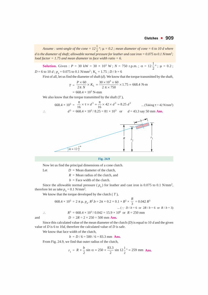
= 8640 (sin 12.5° + 0.25 × 0.2 cos 12.5°) = 2290 N Ans.Example 24.13. Determine the principal dimensions of a cone clutch faced with leather to
transmit 30 kW at 750 r.p.m. from an electric motor to an air compressor. Sketch a sectional frontview of the clutch and provide the main dimensions on the sketch.
�������� � 909
Assume : semi-angle of the cone = 121
2°; µ = 0.2 ; mean diameter of cone = 6 to 10 d where
d is the diameter of shaft; allowable normal pressure for leather and cast iron = 0.075 to 0.1 N/mm2;load factor = 1.75 and mean diameter to face width ratio = 6.
Solution. Given : P = 30 kW = 30 × 103 W ; N = 750 r.p.m. ; α = 121
2° ; µ = 0.2 ;
D = 6 to 10 d ; pn = 0.075 to 0.1 N/mm2 ; KL = 1.75 ; D / b = 6
First of all, let us find the diameter of shaft (d). We know that the torque transmitted by the shaft,
T =3
L60 30 10 60
1.75 668.4 N-m2 2 750
× × ×× = × =π π ×
PK
N
= 668.4 × 10³ N-mm
We also know that the torque transmitted by the shaft (T ),
668.4 × 103 = 3 3 342 8.25
16 16d d d
π π× τ × = × × = ... (Taking τ = 42 N/mm2)
∴ d3 = 668.4 × 10³ / 8.25 = 81 × 103 or d = 43.3 say 50 mm Ans.
Fig. 24.9
Now let us find the principal dimensions of a cone clutch.
Let D = Mean diameter of the clutch,
R = Mean radius of the clutch, and
b = Face width of the clutch.
Since the allowable normal pressure ( pn ) for leather and cast iron is 0.075 to 0.1 N/mm2,therefore let us take pn = 0.1 N/mm2.
We know that the torque developed by the clutch ( T ),
668.4 × 103 = 2 π µ. pn. R2.b = 2π × 0.2 × 0.1 × R2 × 3
R = 0.042 R3
... (∵ D / b = 6 or 2R / b = 6 or R / b = 3)
∴ R3 = 668.4 × 10³ / 0.042 = 15.9 × 10⁶ or R = 250 mm
and D = 2R = 2 × 250 = 500 mm Ans.Since this calculated value of the mean diameter of the clutch (D) is equal to 10 d and the given
value of D is 6 to 10d, therefore the calculated value of D is safe.
We know that face width of the clutch,
b = D / 6 = 500 / 6 = 83.3 mm Ans.From Fig. 24.9, we find that outer radius of the clutch,
r1 =1
2
83.3sin 250 sin 12 259 mm
2 2+ α = + ° =b
R Ans.
910 � ���������������������������
and inner radius of the clutch,
r2 =1
2
83.3sin 250 sin 12 241 mm
2 2− α = − ° =b
R Ans.
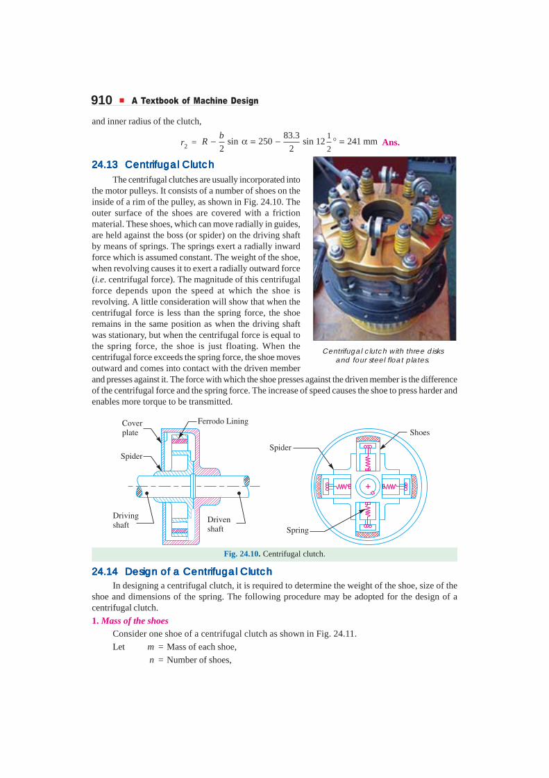
24.1324.1324.1324.1324.13 Centrifugal ClutchCentrifugal ClutchCentrifugal ClutchCentrifugal ClutchCentrifugal ClutchThe centrifugal clutches are usually incorporated into
the motor pulleys. It consists of a number of shoes on theinside of a rim of the pulley, as shown in Fig. 24.10. Theouter surface of the shoes are covered with a frictionmaterial. These shoes, which can move radially in guides,are held against the boss (or spider) on the driving shaftby means of springs. The springs exert a radially inwardforce which is assumed constant. The weight of the shoe,when revolving causes it to exert a radially outward force(i.e. centrifugal force). The magnitude of this centrifugalforce depends upon the speed at which the shoe isrevolving. A little consideration will show that when thecentrifugal force is less than the spring force, the shoeremains in the same position as when the driving shaftwas stationary, but when the centrifugal force is equal tothe spring force, the shoe is just floating. When thecentrifugal force exceeds the spring force, the shoe movesoutward and comes into contact with the driven memberand presses against it. The force with which the shoe presses against the driven member is the differenceof the centrifugal force and the spring force. The increase of speed causes the shoe to press harder andenables more torque to be transmitted.
Fig. 24.10. Centrifugal clutch.
24.1424.1424.1424.1424.14 Design of a Centrifugal ClutchDesign of a Centrifugal ClutchDesign of a Centrifugal ClutchDesign of a Centrifugal ClutchDesign of a Centrifugal ClutchIn designing a centrifugal clutch, it is required to determine the weight of the shoe, size of the
shoe and dimensions of the spring. The following procedure may be adopted for the design of acentrifugal clutch.
1. Mass of the shoesConsider one shoe of a centrifugal clutch as shown in Fig. 24.11.
Let m = Mass of each shoe,
n = Number of shoes,
Centrifugal clutch with three disksand four steel float plates.

�������� � 911
r = Distance of centre of gravity of the shoe from thecentre of the spider,
R = Inside radius of the pulley rim,
N = Running speed of the pulley in r.p.m.,
ω = Angular running speed of the pulley in rad / s = 2 π N / 60 rad/s,
ω1 = Angular speed at which the engagement begins totake place, and
µ = Coefficient of friction between the shoe and rim.
We know that the centrifugal force acting on each shoe atthe running speed,
*Pc = m.ω2.r
Since the speed at which the engagement begins to takeplace is generally taken as 3/4th of the running speed, thereforethe inward force on each shoe exerted by the spring is given by
Ps =2
2 21
3 9( ) . ·
4 16m r m r m r
ω = ω = ω ∴ Net outward radial force (i.e. centrifugal force) with which the shoe presses against the rim
at the running speed
=2 2 29 7
. . . . . .16 16c sP P m r m r m r− = ω − ω = ω
and the frictional force acting tangentially on each shoe,F = µ (Pc – Ps)
∴ Frictional torque acting on each shoe
= F × R = µ (Pc – Ps) R
and total frictional torque transmitted,
T = µ (Pc – Ps) R × n = n.F.R
From this expression, the mass of the shoes (m) may be evaluated.
2. Size of the shoesLet l = Contact length of the shoes,
b = Width of the shoes,
R = Contact radius of the shoes. It is same as the inside radius of the rimof the pulley,
θ = Angle subtended by the shoes at the centre of the spider in radians, and
p = Intensity of pressure exerted on the shoe. In order to ensure reasonablelife, it may be taken as 0.1 N/mm2.
We know that θ = or .3
π= θ =ll R R
R...(Assuming θ = 60° = π / 3 rad)
Fig. 24.11. Forces on a shoe of acentrifugal clucth.
* The radial clearance between the shoe and the rim is about 1.5 mm. Since this clearance is small ascompared to r, therefore it is neglected for design purposes. If, however, the radial clearance is given, thenthe operating radius of the mass centre of the shoe from the axis of the clutch,
r1 = r + c, where c is the radial clearance,
Then Pc = m.ω2 r1 and Ps = m (ω1)2 r1

912 � ���������������������������
∴ Area of contact of the shoe
= l . b
and the force with which the shoe presses against the rim
= A × p = l.b.p
Since the force with which the shoe presses against the rim at the running speed is (Pc – Ps),therefore
l.b.p = Pc – Ps
From this expression, the width of shoe (b) may be obtained.
3. Dimensions of the springWe have discussed above that the load on the spring is given by
Ps = 29. .
16m r× ω
The dimensions of the spring may be obtained as usual.
Example 24.14. A centrifugal clutch is to be designed to transmit 15 kW at 900 r.p.m. Theshoes are four in number. The speed at which the engagement begins is 3/4th of the running speed.The inside radius of the pulley rim is 150 mm. The shoes are lined with Ferrodo for which thecoefficient of friction may be taken as 0.25. Determine: 1. mass of the shoes, and 2. size of the shoes.
Solution. Given : P = 15 kW = 15 × 103 W ; N = 900 r.p.m. ; n = 4 ; R = 150 mm = 0.15 m ;µ = 0.25
1. Mass of the shoes
Let m = Mass of the shoes.
We know that the angular running speed,
ω = 2 2 900
94.26 rad / s60 60
π π ×= =N
Since the speed at which the engagement begins is 3/4 th of the running speed, therefore angularspeed at which engagement begins is
ω1 =3 3
94.26 70.7 rad / s4 4
ω = × =
Assuming that the centre of gravity of the shoe lies at a distance of 120 mm (30 mm less than R)from the centre of the spider, i.e.
r = 120 mm = 0.12 m
We know that the centrifugal force acting on each shoe,
Pc = m.ω2.r = m (94.26)2 0.12 = 1066 m N
and the inward force on each shoe exerted by the spring i.e. the centrifugal force at the engagementspeed, ω1,
Ps = m(ω1)2 r = m (70.7)2 0.12 = 600 m N
We know that the torque transmitted at the running speed,
T =360 15 10 60
159 N-m2 2 900
P
N
× × ×= =π π ×
We also know that the torque transmitted (T ),
159 = µ (Pc – Ps) R × n = 0.25 (1066 m – 600 m) 0.15 × 4 = 70 m
∴ m = 159/70 = 2.27 kg Ans.

�������� � 913
2. Size of the shoes
Let l = Contact length of shoes in mm, and
b = Width of the shoes in mm.
Assuming that the arc of contact of the shoes subtend an angle of θ = 60° or π / 3 radians, at thecentre of the spider, therefore
l = . 150 157 mm3
Rπθ = × =
Area of contact of the shoes
A = l.b = 157 b mm2
Assuming that the intensity of pressure ( p) exerted on the shoes is 0.1 N/mm2, therefore forcewith which the shoe presses against the rim
= A.p = 157b × 0.1 = 15.7 b N ...(i)
We also know that the force with which the shoe presses against the rim
= Pc – Ps = 1066 m – 600 m = 466 m
= 466 × 2.27 = 1058 N ...(ii)
From equations (i) and (ii), we find that
b = 1058 / 15.7 = 67.4 mm Ans.
EEEEEXEXEXEXEXERRRRRCISECISECISECISECISESSSSS
1. A single disc clutch with both sides of the disc effective is used to transmit 10 kW power at 900 r.p.m.The axial pressure is limited to 0.085 N/mm2. If the external diameter of the friction lining is 1.25 timesthe internal diameter, find the required dimensions of the friction lining and the axial force exerted by thesprings. Assume uniform wear conditions. The coefficient of friction may be taken as 0.3.
[Ans. 132.5 mm ; 106 mm ; 1500 N]
Special trailers are made to carry very long loads. The longestload ever moved was gas storage vessel, 83.8 m long.

914 � ���������������������������
2. A single plate clutch with both sides of the plate effective is required to transmit 25 kW at 1600 r.p.m.The outer diameter of the plate is limited to 300 mm and the intensity of pressure between the platesnot to exceed 0.07 N/mm2. Assuming uniform wear and coefficient of friction 0.3, find the innerdiameter of the plates and the axial force necessary to engage the clutch.
[Ans. 90 mm ; 2375 N]
3. Give a complete design analysis of a single plate clutch, with both sides effective, of a vehicle totransmit 22 kW at a speed of 2800 r.p.m. allowing for 25% overload. The pressure intensity is not toexceed 0.08 N/mm2 and the surface speed at the mean radius is not to exceed 2000 m/min. Takecoefficient of friction for the surfaces as 0.35 and the outside diameter of the surfaces is to be 1.5 timesthe inside diameter. The axial thrust is to be provided by 6 springs of about 24 mm coil diameter. Forspring material, the safe shear stress is to be limited to 420 MPa and the modulus of rigidity may betaken as 80 kN/mm2. [Ans. 120 mm ; 80 mm ; 3.658 mm]
4. A multiple disc clutch has three discs on the driving shaft and two on the driven shaft, providing fourpairs of contact surfaces. The outer diameter of the contact surfaces is 250 mm and the inner diameteris 150 mm. Determine the maximum axial intensity of pressure between the discs for transmitting18.75 kW at 500 r.p.m. Assume uniform wear and coefficient of friction as 0.3.
5. A multiple disc clutch employs 3 steel and 2 bronze discs having outer diameter 300 mm and innerdiameter 200 mm. For a coefficient of friction of 0.22, find the axial pressure and the power transmittedat 750 r.p.m., if the normal unit pressure is 0.13 N/mm2.
Also find the axial pressure of the unit normal pressure, if this clutch transmits 22 kW at1500 r.p.m. [Ans. 5105 N ; 44.11 kW ; 0.0324 N/mm2]
6. A multiple disc clutch has radial width of the friction material as 1/5th of the maximum radius. Thecoefficient of friction is 0.25. Find the total number of discs required to transmit 60 kW at 3000 r.p.m.The maximum diameter of the clutch is 250 mm and the axial force is limited to 600 N. Also find themean unit pressure on each contact surface. [Ans. 13 ; 0.034 N/mm2]
7. An engine developing 22 kW at 1000 r.p.m. is fitted with a cone clutch having mean diameter of 300mm. The cone has a face angle of 12°. If the normal pressure on the clutch face is not to exceed 0.07N/mm2 and the coefficient of friction is 0.2, determine :
(a) the face width of the clutch, and
(b) the axial spring force necessary to engage the clutch.
[Ans. 106 mm ; 1796 N]
8. A cone clutch is to be designed to transmit 7.5 kW at 900 r.p.m. The cone has a face angle of 12°. Thewidth of the face is half of the mean radius and the normal pressure between the contact faces is not toexceed 0.09 N/mm2. Assuming uniform wear and the coefficient of friction between the contact facesas 0.2, find the main dimensions of the clutch and the axial force required to engage the clutch.
[Ans. R = 112.4 mm ; b = 56.2 mm ; r1 = 118.2 mm ; r2 = 106.6 mm ; We = 917 N]
9. A soft cone clutch has a cone pitch angle of 10°, mean diameter of 300 mm and a face width of 100mm. If the coefficient of friction is 0.2 and has an average pressure of 0.07 N/mm2 for a speed of 500r.p.m., find : (a) the force required to engage the clutch; and (b) the power that can be transmitted.Assume uniform wear. [Ans. 1470 N ; 10.4 kW]
10. A cone clutch is mounted on a shaft which transmits power at 225 r.p.m. The small diameter of thecone is 230 mm, the cone face is 50 mm and the cone face makes an angle of 15° with the horizontal.Determine the axial force necessary to engage the clutch to transmit 4.5 kW if the coefficient offriction of the contact surfaces is 0.25. What is the maximum pressure on the contact surfaces assuminguniform wear? [Ans. 2414 N ; 0.216 N/mm2]
�������� � 915
11. A soft surface cone clutch transmits a torque of 200 N-m at 1250 r.p.m. The larger diameter of theclutch is 350 mm. The cone pitch angle is 7.5° and the face width is 65 mm. If the coefficient offriction is 0.2, find :
1. the axial force required to transmit the torque;
2. the axial force required to engage the clutch;
3. the average normal pressure on the contact surfaces when the maximum torque is being transmitted; and
4.the maximum normal pressure assuming uniform wear.
[Ans. 764 N ; 1057 N ; 0.084 N/mm2 ; 0.086 N/mm2]
12. A centrifugal friction clutch has a driving member consisting of a spider carrying four shoes which arekept from contact with the clutch case by means of flat springs until increase of centrifugal forceovercomes the resistance of the springs and the power is transmitted by the friction between the shoesand the case.
Determine the necessary mass and size of each shoe if 22.5 kW is to be transmitted at 750 r.p.m.with engagement beginning at 75% of the running speed. The inside diameter of the drum is 300mm and the radial distance of the centre of gravity of each shoe from the shaft axis is 125 mm. Assumeµ = 0.25. [Ans. 5.66 kg ; l = 157.1 mm ; b = 120 mm]
QQQQQUEUEUEUEUESTSTSTSTSTIONSIONSIONSIONSIONS
1. What is a clutch? Discuss the various types of clutches giving at least one practical applicationfor each.
2. Why a positive clutch is used? Describe, with the help of a neat sketch, the working of a jaw or clawclutch.
3. Name the different types of clutches. Describe with the help of neat sketches the working principles oftwo different types of friction clutches.
4. What are the materials used for lining of friction surfaces?
5. Why it is necessary to dissipate the heat generated when clutches operate?
6. Establish a formula for the frictional torque transmitted by a cone clutch.
7. Describe, with the help of a neat sketch, a centrifugal clutch and deduce an expression for the totalfrictional torque transmitted. How the shoes and springs are designed for such a clutch?
Clutches, brakes, steering and transmission need to be carefully designed to ensure theefficiency and safety of an automobile

916 � ���������������������������
OBJECTOBJECTOBJECTOBJECTOBJECTIVEIVEIVEIVEIVE TTTTT YPYPYPYPYPE E E E E QQQQQUEUEUEUEUESTSTSTSTSTIONSIONSIONSIONSIONS
1. A jaw clutch is essentially a
(a) positive action clutch (b) cone clutch
(c) friction clutch (d) disc clutch
2. The material used for lining of friction surfaces of a clutch should have ............ coefficient of friction.
(a) low (b) high
3. The torque developed by a disc clutch is given by
(a) T = 0.25 µ.W.R (b) T = 0.5 µ.W.R
(c) T = 0.75 µ.W.R (d) T = µ.W.R
where W = Axial force with which the friction surfaces are held together ;
µ = Coefficient of friction ; and
R = Mean radius of friction surfaces.
4. In case of a multiple disc clutch, if n1 are the number of discs on the driving shaft and n2 are thenumber of the discs on the driven shaft, then the number of pairs of contact surfaces will be
(a) n1 + n2 (b) n1 + n2 – 1
(c) n1 + n2 + 1 (d) none of these
5. The cone clutches have become obsolete because of
(a) small cone angles (b) exposure to dirt and dust
(c) difficulty in disengaging (d) all of these
6. The axial force (We) required for engaging a cone clutch is given by
(a) Wn sin α (b) Wn (sin α + µ cos α)
(c) Wn (sin α + 0.25 µ cos α) (d) none of these
where Wn = Normal force acting on the contact surfaces,
α = Face angle of the cone, and
µ = Coefficient of friction.
7. In a centrifugal clutch, the force with which the shoe presses against the driven member is the ..............of the centrifugal force and the spring force.
(a) difference (b) sum
ANSWEANSWEANSWEANSWEANSWERRRRRSSSSS
1. (a) 2. (b) 3. (d) 4. (b) 5. (d)
6. (c) 7. (a)