chuong huynh national center for biotechnology information, national library of medicine, national...
Post on 18-Dec-2015
216 views
TRANSCRIPT

Chuong Huynh
National Center for Biotechnology Information,
National Library of Medicine,National Institute of Health
May 21, 2001May 21, 2001
Network Fundamentals:Network Fundamentals:Intro to Network Structure Intro to Network Structure
and Protocoland ProtocolLAN, WAN, TCP/IPLAN, WAN, TCP/IP

Outline
• Basic concepts in communications• Understanding Networking.• Understanding Transmission Medium (Network
Cables)• Understanding Network Hardware• WAN and LAN• Understanding Network Protocols

Basic Concepts in Communication
Basic Concepts
• Communications – activity associated with distributing or exchanging information
• Telecommunications – technology of communications at a distance that permits information to be created any where and used everywhere with little delay
• Today it, involves – Data: digital and analog– Voice: spoken word– Video: telelcommunication imaging

Essentials for Communications
Must have a message
Message must have a transmitter
Message must have a medium
Message must be understood
Message must have some level of security
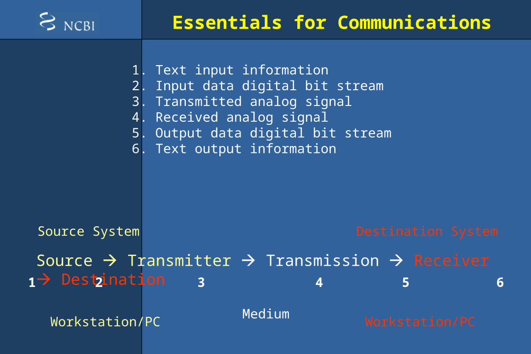
Source Transmitter Transmission Receiver Destination
Source System Destination System
Workstation/PC Workstation/PCMedium
1 2 3 4 5 6
Essentials for Communications
Source Transmitter Transmission Receiver Destination
Source System Destination System
Workstation/PC Workstation/PCMedium
1 2 3 4
1. Text input information2. Input data digital bit stream3. Transmitted analog signal4. Received analog signal5. Output data digital bit stream6. Text output information
5 6

Data Communication Tasks
Data System Utilization
Addressing Multiplexing Capacity Congestion Control
Interfacing Routing Router / Server / Media Control / Protocol
Signal Generation Recovery Repeater/Amplifier; Propagation; Interoperable
Synchronization Messsage Formatting
Signal Begins & Ends
Exchange Management
Security Nature and Timing of Signal
Error Detection & Correction
Network MGT Signal Distortion Bit Error
Flow Control Network MGT Routing Delivery Error Feedback

Understanding Networking

Big Picture
What do you see here for a typical network?

Key Network Terminology Explained (1)
• Networks needs to interconnect at a distance by a form of point to point or point to multiple point connected media
• A network is a group of computers connected together in such a way as to allow
• Networks that are interconnected have proven to be low cost, reliable, and efficient means of communicating at a distance

Key Network Terminology Explained (2)
• Node: anything connected to the network, usually a computer, but it could be a printer or a scanner
• Segment: any portion of a network that is separated by a switch, bridge or a router from another part of a network.
• Backbone: the main cabling of a network that all of the segment connect to. Usually, the backbone is capable of carrying more information than the individual segments.
• Topology: The way each node is physically connected to the network
Network architecture

Common Topologies - Bus
• Bus: each node is daisy-chained (connected one right after the other) along the same backbone. Information sent from a node travels along the backbone until it reaches its destination node. Each end of a bus network
must be terminated with a resistor to keep the

Common Topologies - Ring
• Ring: Similar to a bus network, rings have nodes daisy chained, but the end of the network in a ring topology comes back around to the first node, creating a complete circuit. Each node takes a turn sending and receiving information through the use of a token. The token along with any data is sent from the first node to the second node which extracts the data addressed to it and adds any data it wishes to send. Then second node passes the token and data to the third node, etc. until it comes back around to the first node again. Only the node with the token is allowed to send data . All other nodes must wait for the token to come to them.

Common Topologies - Star
• In a star network, each node is connected to a central device called a hub. The hub takes a signal that comes from any node and passes it along to all the other nodes in the network.
•A hub does not perform any type of filtering or routing of the data. •A hub is a junction that joins all the different nodes together.

Common Topologies - Star
• In a star network, each node is connected to a central device called a hub. The hub takes a signal that comes from any node and passes it along to all the other nodes in the network.

Common Topologies – Star Bus
• Prob. Most common topology used today. Combines elements of the star and bus topologies to create a versatile network environment.
• Nodes in particular areas are connected to hubs (and create star topology), and hubs are connected together along the network backbone (like a bus network).
• Often you have stars nested within stars.

Other network topologies (architecture)
• Some basic network topologies not previously mentioned:
• One-to-one• Hierarchical• Hybrid• Client-server• Multiple nodes

Key Network Terminology Explained (3)
• Simplex: information flows in only one direction• Half-duplex: information flows in two directions,
but only in one direction at a time.• Full-duplex: information flows in two directions
at the same time

Basic Signal Terminologies
• Bit: binary digit, either 0 or 1• Baud (don’t really use anymore; not accurate) =
one electronic state change per second• Bit rate – a method for measuring data
transmission speed – bits per second• Mbps – millions of bits per second (data speed;
measure of bandwidth = total information flow over a given time) on a telecommunication medium
• 8 bits = 1 byte• Mb – million bits (quantity of data)• MB – million bytes (quantity of data)• Gbps – Billion bits per second (data speed)• Teraflops – trillion operations per second
Kilo K 2^10Mega M 2^20Giga G 2^30Tera T 2^40Peta P 2^50Exa E 2^60Zetta Z 2^70Yotta Y 2^80

Data Transmission
• Successful transmission of data depends on:– The quality of the signal being transmitted– Characteristics of the transmission medium
• Data rate – bits per second in data communications
• Bandwidth – bandwidth or signal is constrained by the transmitter and the nature of the transmission in cycles per second or hertz
• Noise – Average level of noise over the communication path.
• Error rate – rate at which errors occur where error in 1 or 0 bit occurs

Understanding Transmission Medium

Basic transmission medium concepts
• Medium is the physical path between transmitter and receiver in a data transmission system
• Guided Medium: waves are guided along a solid medium path (twisted pair, coaxial cable, and optical fiber).
• Unguided medium: waves are propagated through the atmosphere and inner/outerspace (satellite, laser, and wireless transmissions).

Medium examples by type
• Conductive: twisted pairs and coaxial cables• Electromagnetic: microwave• Light: lasers and optical fibers (need clear line
of sight)• Wireless – inner/outerspace; satellite
(omnidirectional security issues)

Coaxial cable (1)
• Widely installed for use in business and corporation ethernet and other types of LANs.
• Consists of inter copper insulator covered by cladding material, and then covered by an outer jacket
• Physical Descriptions:
Covered by sheath material Outer conductor is braided shielded (ground)
Separated by insulating material
Inner conductor is solid copper metal

Coaxial cable (2)
• Applications:– TV distribution (cable tv); long distance telephone
transmission; short run computer system links
– Local area networks
• Transmission characteristics:– Can transmit analog and digital signals
– Usable spectrum for analog signaling is about 400 Mhz
– Amplifier needed for analog signals for less than 1 Km and less distance for higher frequency
– Repeater needed for digital signals every Km or less distance for higher data rates
– Operation of 100’s Mb/s over 1 Km.

Twisted Pair Cables
• Physical description:– Each wire with copper conductor
– Separately insulated wires
– Twisted together to reduce cross talk
– Often bundled into cables of two or four twisted pairs
– If enclosed in a sheath then is shielded twisted pair (STP) otherwise often for home usage unshielded twisted pair (UTP). Must be shield from voltage lines
• Application:– Common in building for digital signaling used at speed of
10’s Mb/s (CAT3) and 100Mb/s (CAT5) over 100s meters.
– Common for telephone interconnection at home and office buildings
– Less expensive medium; limited in distance, bandwidth, and data rate.

Categories of Twisted Pairs Cabling System
Specs describe cableMaterial, type of Connectors, andJunction blocks toConform to a category
Category Maximum data rate
Usual application
CAT 1 Less than 1 Mbps
analog voice (plain old telephone service) Integrated Services Digital Network Basic Rate Interface in ISDN Doorbell wiring
CAT 2 4 Mbps Mainly used in the IBM Cabling System for token ring networks
CAT 3 16 Mbps Voice and data on 10BASE-T Ethernet (certify 16Mhz signal)
CAT 4 20 Mbps Used in 16Mbps Token Ring
Otherwise not used much
CAT 5 100 Mbps 100 Mbps TPDDI
155 Mbps asynchronous transfer mode (certify 100 Mhz signal)

Optical Fibers (1)
• Physical Description:– Glass or plastic core of optical fiber = 2to125 µm– Cladding is an insulating material– Jacket is a protective cover– Laser or light emitting diode provides transmission
light source
• Applications:– Long distance telecommunication– Greater capacity; 2 Gb/s over 10’s of Km– Smaller size and lighter weight– Lower attenuation (reduction in strength of signal)– Electromagnetic isolation – not effected by external
electromagnetic environment. Aka more privacy– Greater repeater spacing – fewer repeaters, reduces
line regeneration cost
Repeaters

Optical Fibers (2)
• multimode fiber is optical fiber that is designed to carry multiple light rays or modes concurrently, each at a slightly different reflection angle within the optical fiber core. used for relatively short distances because the modes tend to disperse over longer lengths (this is called modal dispersion) .
• For longer distances, single mode fiber (sometimes called monomode) fiber is used. In single mode fiber a single ray or mode of light act as a carrier

Wireless Transmission (1)
• Frequency range (line of sight):– 26 GHz to 40 GHz: for microwave with highly
directional beam as possible– 30 MHz to 1 GHz: for omnidirectional applications– 300MHz to 20000 GHz: for infrared spectrum; used
for point to point and multiple point application (line of sight)
• Physical applications:– Terrestrial microwave – long haul telecommunication
service (alternative to coaxial or optical fiber)– Few amplifier and repeaters– Propagation via towers located without blockage from
trees, etc (towers less than 60 miles apart)

Wireless Transmission (2)
• Satellite is a microwave relay station• Geostationary orbit (22,000 miles) and low orbit (12000
miles)• Satellite ground stations are aligned to the space satellite,
establishes a link, broadcast at a specified frequency. Ground station normally operate at a number of frequencies – full duplex
• Satellite space antenna is aligned to the ground station establishes a link and transmits at the specified frequency. Satellite are capable of transmitting at multiple frequencies simultaneously, full duplex.
• To avoid satellites from interfering with each other, a 4 degree separation is required for 4/6 GHz band and 3 degree for 12/14 GHz band. Limited to 90 satellites.
• Disadv: not satellite repair capability; greater delay and attenuation problems.

Wireless LAN
• Wireless LAN• HiperLAN (European standard; allow
communication at up to 20 Mbps in 5 GHz range of the radio frquency (RF) spectrum.
• HiperLAN/2 operate at about 54 Mbps in the same RF band.

Network Hardware

Hubs
• A hub is the place where data converges from one or more directions and is forwarded out in one or more directions.
• Seen in local area networks
Reference toequipment

Gateways
• A gateway is a network point that acts as an entrance to another network. On the internet, in terms of routing, the network consists of gateway nodes and host nodes.
• Host nodes are computer of network users and the computers that serve contents (such as Web pages).
• Gateway nodes are computers that control traffic within your company’s network or at your local internet service provider (ISP)

Routers
• A router is a device or a software in a computer that determines the next network point to which a packet should be forwarded toward its destination.
• Allow different networks to communicate with each other
• A router creates and maintain a table of the available routes and their conditions and uses this information along with distance and cost algorithms to determine the best route for a given packet.
• A packet will travel through a number of network points with routers before arriving at its destination.

Bridge
• a bridge is a product that connects a local area network (LAN) to another local area network that uses the same protocol (for example, Ethernet or token ring).
• A bridge examines each message on a LAN, "passing" those known to be within the same LAN, and forwarding those known to be on the other interconnected LAN (or LANs).

What is the difference between?
• Bridge: device to interconnect two LANs that use the SAME logical link control protocol but may use different medium access control protocols.
• Router: device to interconnect SIMILAR networks, e.g. similar protocols and workstations and servers
• Gateway: device to interconnect DISSIMILAR protocols and servers, and Macintosh and IBM LANs and equipment

Switches
• Allow different nodes of a network to communicate directly with each other.
• Allow several users to send information over a network at the same time without slowing each other down.

WANs and LANs
Major Categories of Networks
• Local Area Networks (LAN)– A network of computers that are in the same general
physical location, within a building or a campus.
• Metropolitan Area Networks (MAN)• Wide Area Networks (WAN)
Issues of size and breadth.

Data Communications Through WANs (1)
• WANs were developed to communicate over a large geographical area (e.g. lab-to-lab; city-to-city; east coast-to-west coast; North America-to-South America etc)
• WANs require the crossing of public right of ways (under control and regulations of the interstate commerce and institute of telephone and data communications established by the gov’t and international treaties).
• WANs around the world relies on the infrastructure established by the telephone companies (“common carrier”) or public switched telephone network (PSTN).
• WANs consists of a number of interconnected switching nodes (today = computers). Transmission signals are routed across the network automatically by software control to the specified destination. The purpose of these nodes are to route messages through switching facilities to move data from node to node to its destination.

Data Communications Through WANs (2)
• WANs originally implemented circuit switching and packet switching technologies. Recently, frame relay and asynchronous transfer mode (ATM) networks have been implemented to achieve higher operating and processing speeds for the message.
• WAN transmission speeds are _______• WAN are owned by the common carrier in the
U.S. and governement in most foreign countries.
• Interconnected devices, I.e. LANs or Personal Computers (PC) or Workstation or Servers can be (usually are) privately owned by companies.

Circuit Switching Technologies
• Circuit switching is a dedicated communications path established between two stations or multiple end points through nodes of the WAN
• Transmission path is a connected sequence of physical link between nodes.
• On each link, a logical channel is dedicated to the connection. Data generated by the source station are transmitted along dedicated path as rapidly as possible.
• At each node, incoming data are routed or switched to the appropriate outgoing channel without excessive delay. However, if data processing is required, some delay is experienced.
• Example of circuit switching above is the telephone networks.

Packet Switching Technologies
• It is not necessasry (as in circuit switching) to dedicate transmission capacity along a path through the WAN rather data are sent out in a sequence of small chucks, called packets.
• Each packet, consisting of several bits is passed through the network from node to node along some path leading from the source to the destination
• At each node along the path, the entire packet is received, stored briefly, and then transmitted to the next node.
• At destination all individual packets are assembled together to form the complete text and message from the source. Each packet is identified as to its place in the overall text for reassembly.
• Packet switching networks are commonly used for terminal-to-computer and computer-to-computer communications.
• If packet errors occur, the packet is retransmitted.
Frame Relay Techniques
• Packet switching was developed at a time (1960’s) when digital long distance transmission facilities exhibited a relatively high error rate compared to today’s facilities. A large amount of overhead was included for error detection and control. Each packet included additional bits and each node performed additional processing to insure reliable transmission.
• Frame relay has removed the overhead bits and additional processing. It has become unnecessary to invoke these overhead checks and thereby enables higher capacity transmission rates.
• Frame relay takes advantage of these high rates and low error rates.
• Frame relay networks are designed to operate efficiently at user data rates of 2 Mb/s and higher. (packet switching originally designed with a 64 Kb/s data rate to the end user).
• Frame relay achieves these higher rates by stripping out most of the overhead involved with error control.

Asynchronous Transfer Mode (ATM)
• ATM also referred to as “Cell Relay”• Evolution from frame relay and circuit switching.• Major differences: Frame relay uses variable length
packets called “frames”. ATM uses fixed length packets called “cells”.
• ATM provides little overhead for error control like frame relay, and depends on inherent reliability of the transmission system and on higher layers of logic in the end systems to identify and correct errors.
• ATM is designed to operate in range of 10s to 100 Mb/s compared to frame relay (2 Mb/s)
• ATM allows multiple virtual channels with higher data rates for transmission paths. Each channel dynamically sets on demand.

ISDN and Broadband ISDN Technology
• Integrated services digital network (ISDN) was intended to be a world wide public telecommunication network to replace existing public telecommunication networks and deliver a wide variety of services.
• ISDN has standardized user interfaces, implemented a set of digital switches and paths supporting a broad range of traffic types and providing a value added processing service
• ISDN is multiple networks, but integrated to provide user with single, uniform accessibility and world wide interconnection.
• First generation ISDN was narrowband, 64 Kb/s channel of switching and circuit switching orientations. Frame relay resulted from the ISDN narrowband efforts.
• Second generation is broadband ISDN. It supports high data rates of 100s Mb/s and has a packet switching orientation. ATM resulted from the broadband ISDN efforts.
Local Area Network
• Small interconnected of personal computers or workstations and printers within a building or small area up to 10 Kms.
• Small group of workers that share common application programs and communication needs.
• LANs are capable of very high transmission rates (100s Mb/s to G b/s).
• LAN equipment usually owned by organization. Medium may be owned or leased from telephone company provider or common carrier.
• PC or Workstation interconnected to medium (twisted pair; fiber optics; etc) through concentrators to servers. LAN is interconnected with other networks via switches and router/gateways.
• Advanced LANs using circuit switching are available. ATM LANs, fibre channel baseband, and broadband LANs are being used. Etc.
1. Ethernet2. Token Ring

What is ethernet?
• A group of standards for defining a local area network that includes standards in cabling and the structure of the data sent over those cables as well as the hardware that connects those cables.
• Independent of the network architecture• Flavors of ethernet• IEEE 802.3 Ethernet Specification
– Great detail specifying cable types, data formats, and procedures for transferring that data through those cables
• IEEE 802.5 Token Ring Specification

Network Interface Card (NIC)
• Every computer and most devices (e.g. a network printer) is connected to network through an NIC. In most desktop computers, this is an Ethernet card (10 or 100 Mbps) that is plugged into a slot on the computer motherboard.

How does Ethernet work?
• Using MAC addresses to distinguish between machines, Ethernet transmits frames of data across baseband cables using CSMA/CD (IEEE 802.3)

What is a MAC Address?
• Media Access Control (MAC) Address – are the physical address of any device, e.g. a NIC in a computer on the network. The MAC address has two parts of 3 bytes long. The first 3 bytes specify the company that made the NIC and the second 3 bytes are the serial number of the NIC.

What is a Token Ring?
• All computers are connected in a ring or star topology and a binary digit or token passing scheme is used in order to prevent the collision of data between two computers that want to send messages at the same time.

How do Token Rings work?
1. Empty information frames are continuously circulated on the ring.
2. When a computer has a message to send, it inserts a token in an empty frame (this may consist of simply changing a 0 to a 1 in the token bit part of the frame) and inserts a message and a destination identifier in the frame.
3. The frame is then examined by each successive workstation. If the workstation sees that it is the destination for the message, it copies the message from the frame and changes the token back to 0.
4. When the frame gets back to the originator, it sees that the token has been changed to 0 and that the message has been copied and received. It removes the message from the frame.
5. The frame continues to circulate as an "empty" frame, ready to be taken by a workstation when it has a message to send.

Understanding Network Protocols

Protocols of Computer Communications and Networks
• Protocol are used for communication between computers in different computer networks. Protocol achieves:– What is communicated between computers?
– How it is communicated?
– When it is communicated?
– What conformance (bit sequence) between computers?
• Key elements of a protocol are:– SYNTAC: Data format and signal levels
– SEMANTICS: Control information for coordination and error handling
– TIMING: Synchronization, speed matching, and sequencing
• Examples of protocols:– WAN Protocol: TCP/IP
– LAN Protocol: Media Access Control; Contention; Token Passing
Protocol Architecture
• Architecture provides high degree of cooperation between two computers.
• Example:
• INSERT DIAGRAM of file transfer

ISO/OSI Reference Model (1)
• Open Systems Interconnection• No one really uses this in the real world. • A reference model so others can develop
detailed interfaces. • Value: The reference model defines 7 layers of
functions that take place at each end of communication and with each layer adding its own set of special related functions.
• Flow of data through each layer at one

ISO/OSI Reference Model (2)
How to transmit signal; codingHardware means of sending and receiving data on a carrier
Two party communication: Ethernet
Routing and Forwarding Address: IP
End-to-end control & error checking (ensure complete data transfer): TCP
Establish/manage connection
ASCII Text, Sound (syntax layer)
File Transfer, Email, Remote Login

What is TCP/IP?
• Transmission Control Protocol (TCP) – uses a set of rules to exchange messages with other Internet points at the information packet level
• Internet Protocol (IP) – uses a set of rules to send and receive messages at the Internet address level
• Is the predominate network protocol in use today (Other includes OSI Model) for interoperable architecture and the internet.
• TCP/IP is a result of protocol research and development conducted on experimental packet switched network by ARPANET funded by the defense advanced research projects agency (DARPA). TCP/IP used as internet standards by the internet architecture board (IAB).

TCP/IP Five Independent Levels
• Application Layer: contains the logic needed to support the various user applications. Separate module are required for each application.
• Host-to-host or transport Layer: collection of mechanisms in a single and common layer
• Internet Layer: IP provides the routing functions across the multiple networks
• Network access layer: concerned with access to and routing data across a network for two end systems attached to the same network.
• Physical Layer: covers physical interface between PC or workstation and a transmission medium or network
HTTP / FTP / Telnet / SMTP / SLIP / PPP
TCP keep track of the individual packets And reassemble
IP handles actual delivery of packets
TCP (example)
• Web Server: serves HTML pages• TCP layer in the server divides the file into one
or more packets, numbers the packet, then forward packets individually to IP.
• Note: each packet has the same destination IP address, it may get routed differently through the network.
• TCP (on the client) reassembles the individual packets and waits until they have arrived to forward them as a single file.
• Connection-oriented protocol

IP
• Connectionless protocol (I.e. no established connection between the end points that are communicating.)
• Responsible for delivery the independently treated packet !!!!
• TCP responsible for reassembly.

Associated TCP/IP Protocols & Services
HTTP This protocol, the core of the World Wide Web, facilitates retrieval and transfer of hypertext (mixed media) documents. Stands for the HyperText Transfer protocol
Telnet A remote terminal emulation protocol that enables clients to log on to remote hosts on the network.
SNMP Used to remotely manage network devices. Stands for the Simple Network Management Protocol.
DNS Provides meaningful names like achilles.mycorp.com for computers to replace numerical addresses like 123.45.67.89. Stands for the Domain Name System.
SLIP/ PPP
SLIP (Serial Line Internet Protocol) and PPP (Point to Point Protocol) encapsulate the IP packets so that they can be sent over a dial up phone connection to an access provider’s modem.

Considerations?

Examples
• Multimedia (audio/video stream) Bioinformatics Educational CD’s as an example of extending network capacity

Further Readings
• Basics: Complete Idiots Guide to Networking, 3rd Edition (Wagner and Negus)
• Practical Network Cabling (Freed and Derfler)• Networking books by William Stallings:
– Business Data Communications– Operating Systems: Internals and Design Principles– Data & Computer Communications– Local and Metropolitan Area Networks– High-speed networks TCP/IP and ATM Design
Principles
• Online Audio/Video Recording of Networking Class:– http://www.cis.ohio-state.edu/~jain/videos.htm