c&i ppt
DESCRIPTION
C&ITRANSCRIPT

CONTROL & INSTRUMENTATION / FB
CUSTOMER TRAINING PROGRAM
VENUE:
BHEL, HRDC,
TRICHIRAPALLI – 14.
TITLE:
OPERATION, MAINTENANCE & CARE OF BOILERS
LECTURE ON:
OPERATION & MAINTENANCE OF CONTROL &
INSTRUMENTATION
FACULTY:
Mr. R.ANBARASU, DGM.-C&I/FB.

1. Control Systems & its Types
Pneumatic Control
Hydraulic Control
Electrical Control
2. Furnace Safeguard Supervisory System (FSSS)
3. Programmable logic control (PLC)
4. Auto Control System
5. Instrumentation
Pressure Measurement
Temperature Measurement
Level Measurement
Flow Measurement
Vibration Measurement
Over view

6. New products introduced (BHEL make-Indigenous))
EWLI-Electronic Water Level Indicator
BHELMHO Switch
BHELSONIC-Sonic tube leak detection system
BHELFEED-Microprocessor based Gravimetric
Feeder control system
BHELSCAN- Microcontroller based Flame Scanner system
7. Trouble shooting
Problems in Safe Flame Scanner System


CONTROL SYSTEMS
&ITS TYPES
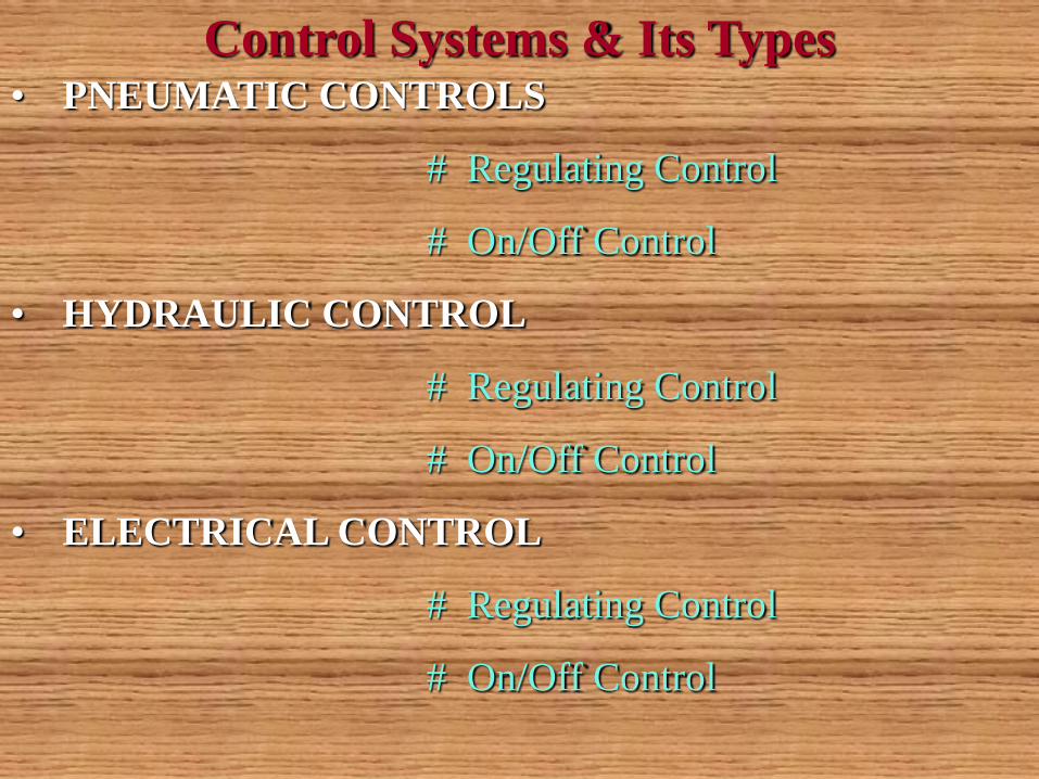
• PNEUMATIC CONTROLS
# Regulating Control
# On/Off Control
• HYDRAULIC CONTROL
# Regulating Control
# On/Off Control
• ELECTRICAL CONTROL
# Regulating Control
# On/Off Control
Control Systems & Its Types

Pneumatic Control

Open/Close Power Cylinder
S
S
AIR LOCK
AFR

Regulating Power Cylinder
AIR LOCK
I
P
ZT
4-20mA
4-20mA
AIR SUPPLY
AIR FILTER
REGULATOR
AFR
POSITION
TRANSMITTER
E/PPositioner

Pneumatic Valve (Air to Close Type)
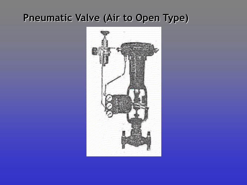
Pneumatic Valve (Air to Open Type)

I/P CONVERTER
Hydraulic Control


Electrical Control

Electrical Control Circuit (Of Soot Blower)

Motor Control (Of Soot Blower)

Motor Control Centre (MCC)

Motor Control Centre (MCC)

Electric Actuator

AUTO CONTROL SYSTEM

Autocontrol Legends / Definitions
No Function Symbol Definition
1 SUMMING The outputs Equals the Algebraic
Sum of the Inputs
2 Averaging The outputs Equals the Algebraic
sum of the inputs divided by the
number of inputs
3 Difference The outputs equals the Algebraic
difference between two inputs
4 Proportional The output is directly proportional
to the input
5 Integral The output varies in accordance
with both magnitude and duration
of the input.The output is
proportional to the integral of the
input.
K or P
/n

Autocontrol Legends / Definitions
No Function Symbol Definition
6 Derivative The outputs is proportional to the
rate of change (derivative) of the
input.
7 Multiplying The outputs Equals the products of
the two inputs.
8 Dividing The outputs equals the Quotient of
the two inputs
9 Root Extractor The output equals the root
10 Nonlinear or
unspecified
Function
The output equals some nonlinear
function of the input.
D or d/dt
X
F(x)
.
.
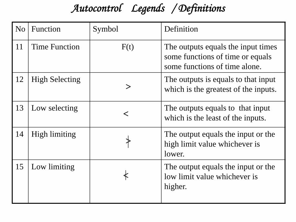
Autocontrol Legends / Definitions
No Function Symbol Definition
11 Time Function F(t) The outputs equals the input times
some functions of time or equals
some functions of time alone.
12 High Selecting The outputs is equals to that input
which is the greatest of the inputs.
13 Low selecting The outputs equals to that input
which is the least of the inputs.
14 High limiting The output equals the input or the
high limit value whichever is
lower.
15 Low limiting The output equals the input or the
low limit value whichever is
higher.
>
<
<
>

Autocontrol Legends / Definitions
No Function Symbol Definition
16 Reverse
proportional
The outputs is reversely
proportional to the input
17 Bias The outputs Equals the input plus
(or minus) some arbitarary value.
18 Analog signal
Generator
The outputs is an analog signal
developed with in the generator.
19 Transfer The output equals input which has
been selected by transfer the state
of the transfer is established by
external means.
-K or -P
+,- or
T
A


CAUSES OF FURNACE EXPLOSIONS
INCORRECT OR INADEQUATE IGNITION
PROCEDURE
FUEL SUPPLY WITH OUT ESTABLISHING
COMBUSTION
INTRODUCTION OF MAIN FUEL WITH OUT
ADEQUATE IGNITION ENERGY

FUNCTIONS OF FSSS
BOILER PURGE
SECONDARY AIR DAMPER MODULATION & ON -
OFF CONTROL
IGNITOR ON - OFF OPERATION
WARM UP FUEL ON - OFF OPERATION
MILL AND FEEDER ON - OFF OPERATION
FLAME SCANNING
BOILER TRIP PROTECTION.

Boiler Wind box Arrangement

Digital Gates
OR
AND
S
R
‘OR’ GATE
‘AND’ GATE
‘NOT’ GATE
‘ON DELAY’ TIMER
‘OFF DELAY’ TIMER
FLIP FLOP / MEMORY
O/P
O/P
O/P
O/PO/P
O/P 2
O/P 1
I/P SIGNAL 1
2
3
I/P SIGNAL 1
2
3
I/P
I/P
I/P 1I/P 2
I/P

Boiler Trip Protection
M.F.R
Y
F.D. FAN(S) OFF
F.D. FAN(S) OFF
EMERGENCY TRIP
2/3 FURNACE PRESSURE ‘HIGH’
2/3 FURNACE PRESSURE ‘LOW’
TURBINE TRIPPED
2/3DRUM LEVEL ‘ LOW’
2/3 DRUM LEVEL ‘HIGH’
AIR FLOW < 30
FALME FAILURE TRIP
RESET M.F.R. TO
BOILER TRIP
BOILER TRIP
LOSS OF FUEL TRIP

FURNACE PURGE SUPERVISION
M.F.R
YG
W
ALL IGNITION VALVES CLOSED
ALL HEAVY OIL VALVES CLOSED
ALL LIGHT OIL VALVES CLOSED
FUEL GAS TRIP VALVES CLOSED
FUEL GAS CORNER N.V. CLOSED
ALL SCANNERS SHOW NO FLAME
IGNITION TRIP VALVE CLOSED
ALL AUXILIARY AIR DAMPERS MODULATING
LIGHT OIL TRIP VALVE CLOSED
HEAVY OIL TRIP VALVE CLOSED
NO BOILER TRIP
PURGE START
PURGE
READY
PURGING
5 MIN
RESET M.F.R. TO
NO BOILER TRIP
PURGE
COMPLETE AND
NO BOILER TRIP
PROGRAMMABLE LOGIC CONTROL

WHAT IS A PLC?
•PLC is short for Programmable Logic Controller. A more common name would be industrial computer.
•PLC is the heart of most modern factories using automation to increase the productivity.
•It has a power supply, microprocessor chip, RAM, input / output and com ports.
•It can sense large number of inputs and control a large number of outputs all in a matter of milliseconds.
•It uses symbolic programming language.
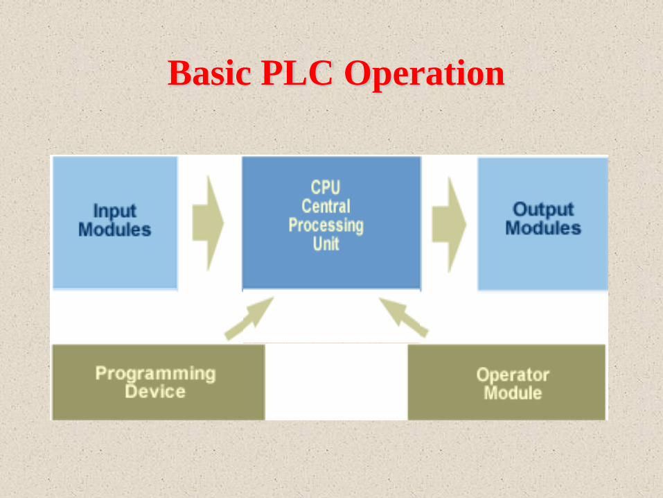
Basic PLC Operation
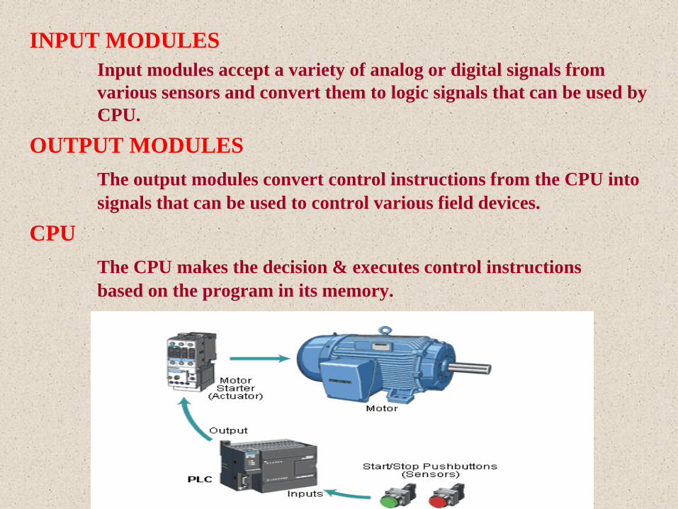
INPUT MODULES
Input modules accept a variety of analog or digital signals from
various sensors and convert them to logic signals that can be used by
CPU.
OUTPUT MODULES
The output modules convert control instructions from the CPU into
signals that can be used to control various field devices.
CPU
The CPU makes the decision & executes control instructions
based on the program in its memory.

PROGRAMMING DEVICE
Programming device is used to install the instructions that
determine what the PLC has to do in response to specific inputs.
OPERATOR MODULE
The operator interface allows the process information to be
displayed and new parameters to be entered.

Processor Configuration & Hardware Requirement
• The system shall have dynamic self diagnostic features
and indication for each component failure.
• Redundant central processing units(CPU).
• Redundant I/O system for critical outputs and non-
redundant I/O system for remaining I/Os.
• Engineering console with interface
• Operating console with interface.
• Communication system.
• The CPU shall have capability to meet the following minimum requirement.
a) Logic functions
b) Timing functions
c) Counter
d) Any other functional capabilities to perform the system requirement.
• The communication between the sub-system shall be redundant and with complete error checking.
• In case of redundant processors, the failure of any processor or any other component shall not affect the operation and the other processor shall take over the complete operation smoothly
Processor Configuration & Hardware Requirement
…contd.

• On-line replacement of failed processor after rectification shall be possible , without affecting the operation.
• Redundancy shall be provided for the complete processor system including CPU, memory, power supply, and communication sub-system.
• The failure of any single component shall not cause the control system to be completely inoperative and thus ensuring total system availability.
• The failure of a processor or any other component shall be annunciated.The minimum requirements are:
Processor failure
Memory failure
I/O module failure
Communication link failure
Battery voltage level low.
Processor Configuration & Hardware Requirement
…contd.

• On failure of a Processor in the system, it shall be possible for
the outputs to be individually freezed, opened or closed.
• On resumption of power supply after a failure, all outputs
shall either open or close as dictated by the process.
• Each processor shall be provided with a separate power
supply and failure of one power supply shall not affect the
operation.
• Processor offered shall be suitable to accommodate at least
30% spare capacity.
Processor Configuration & Hardware
equirement…contd.

SCOPE OF INSTRUMENTATION
AUTOMATIC REGULATING CONTROL
AUTOMATIC SEQUENCE CONTROL
INTERLOCKING
PROTECTION
PERFORMANCE CHARACTRISTICS
ACCURACY
RESPONSE TIME
REPEATABILITY
OPERATING TEMP. RANGE
INSTRUMENTATION

VARIABLES IN MEASUREMENTS
PRESSURE
TEMPERATURE
LEVEL
FLOW
CONDUCTIVITY
VIBRATION
ANALYSER
DENSITY
ENVIRONMENTAL POLLUTANTS

SIMPLE MANOMETER
INCLINED
MANOMETER
CYSTERN
MANOMETER
PRESSURE MEASUREMENT

DIAPHRAGM
PRESSURE
GAUGE
BELLOW PRESSURE
GAUGE
BOURDON
PRESSURE
GAUGE

Pressure Transmitters

PRESSURE GAUGES & TRANSMITTERS
Low pressure
Diaphragm
Gauge
Absolute
Pressure
Transmitter
Diaphragm
sealed Gauge
Pressure
Transmitter

DIFFERENTIAL PRESSURE TRANSMITTERS
Differential Static Pressure
Transmitter
Diaphragm sealed
Differential Pressure
Transmitter

PRESSURE SWITCHES & TRANSDUCERS
Pressure Switch Industrial Pressure
Transducer
Diaphragm Pressure
Transducer
Pressure Indicator

DIFFERENTIAL PRESSURE SWITCHES &
TRANSDUCERS
Differential
Pressure
Transducer
Differential Pressure
Switch

TEMPERATURE MEASUREMENT
Expansion Thermometers
Resistance Thermometers
Thermocouples
Pyrometers
Thermistors
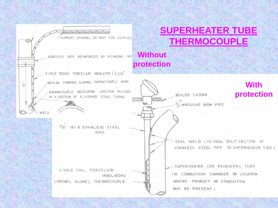
SUPERHEATER TUBE
THERMOCOUPLE
Without
protection
With
protection

Mercury In Glass
Thermometer
EXPANSION THERMOMETERS
Mercury In Steel
Thermometer
Bimetallic
Thermometers
Vapour Pressure
Thermometers

THERMOCOUPLE
K TYPE
THERMISTOR

Temperature Transmitters
Temperature Indicator
RTD

Optical Pyrometer Emissivity Calculator
Pyrometer
PYROMETERS

TEMPERATURE MEASUREMENT IN BOILER

DRUM LEVEL MEASUREMENT IN
BOILER

FLOW MEASUREMENT
Orifice Plate
Flow Nozzle
Venturi Tube
Area Flow Meter
1.Rotameter
2.Piston Type Meter

Venturi TubeFlow Nozzle
Orifice plate

PD FLOW METERS

PD flow meter : Positive Displacement Meter
Principle of measurement : Displacement of oil by volume. Hence it is known as PD flow meter.
PD flow meters are commonly used for fuel oil flow measurement.
PD flow meter
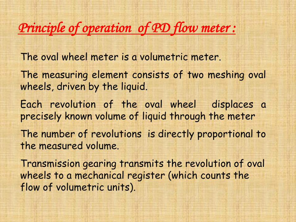
Principle of operation of PD flow meter :
The oval wheel meter is a volumetric meter.
The measuring element consists of two meshing ovalwheels, driven by the liquid.
Each revolution of the oval wheel displaces aprecisely known volume of liquid through the meter
The number of revolutions is directly proportional to the measured volume.
Transmission gearing transmits the revolution of oval wheels to a mechanical register (which counts the flow of volumetric units).
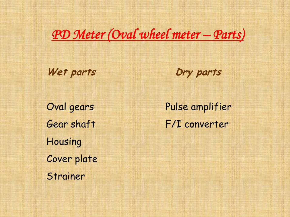
PD Meter (Oval wheel meter – Parts)
Wet parts Dry parts
Oval gears Pulse amplifier
Gear shaft F/I converter
Housing
Cover plate
Strainer

Strainer :
Protect the oval wheel meters from solid matterin oil.
Select strainers with 250 microns.
Pulse amplifier :
Generates and amplifies weak pulses proportionalto the volume of oil displaced thro’ the flow meter.
F to I converter :
Converts the pulse generated by the pulsegenerator into a linear 4 – 20 mA current signal.
PD Meter Parts
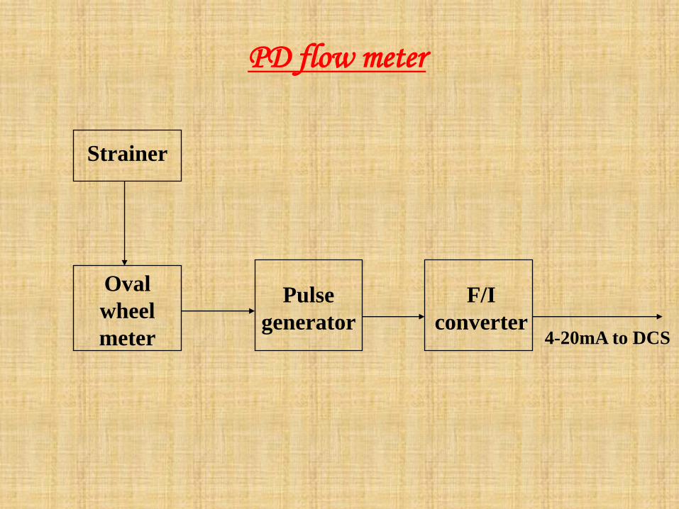
Strainer
Oval
wheel
meter
Pulse
generator
F/I
converter4-20mA to DCS
PD flow meter

Problems faced in recent projects in PD Flow
meter:
Kothagudam
Frequent stuck up in the meter
Jindal
F/I converter defective. Shaft coupling damaged.
Jojobera
Problem in connecting F/I converter sorted out

PD Flow Meter …..Contd…..
Unchahar
Wrong pulse amplifier settings.
Vindyachal
F/I converter incorrect switch setting.
Kaperkheda
Oval gear tooth was damaged and shaft was slightlybent due to over speeding.

PD Flow Meter …..Contd…..
WCPM
Problem in F-I converter rectified and reinstalled.
Ennore
Damage in strainer insert due to entry welding bur’s.
Recommendation for reducing/avoiding problems :
The major problem faced in the PDFM :
Improper installation of the meter andimproper setting of the F/I converter.
To avoid Installation problem :
Brief notes with method of installation and Do’sand Don’ts during installation.
Since the O&M manual does not reach at theappropriate time.

Alternate meter :
Since mass flow meter is very costly whencompared with the PD flow meter and the problemsfaced with PD flow meter are not mainly due to thedefect in the equipment but are installationproblems, PD flow meter itself shall be envisagedfor this application with incorporating therecommended procedure.
Mass Flow Meter …..Contd…..

VELOCITY PICKUPSEISMIC DEVICE
PIEZO ELECTRIC
SENSOR
VIBRATION MEASURING INSTRUMENTS

ENCLOSURE PROTECTION
Degree of Enclosure Protection for
Electrical and Electronic Equipments.

Degrees of Protection
FIRST NUMERAL
IP X X
SECOND NUMERAL
X - : First Numeral stands for :
“ Degree of protection against ingress of solid particles ”.
-X : Second Numeral Stands for :
“ Degrees of protection against ingress of Moisture ”.
The above is as per IS 2147 which is now superseded by
IS 13947 – 1.
----- why?

We have now the degrees of protection as
IP 4 L 4
Characteristic letters.
1st characteristic numeral.
Supplementary letter.
2nd characteristic letters.

1st
Numeral
& suffix
Short description Definition
1. Protection against solid objects greater
than 50 mm.
-
2L. Protection against solid objects greater
than 12.5 mm and against contact by
standard test finger.
Protection against contact with live and
moving parts.
Test finger – Not exceeding 80 mm length.
3. Protection against solid objects greater
than 2.5 mm.
-
3 L. Protection against solid objects greater
than 12.5 mm and against contact by
2.5 mm probe.
Protection against contact with live and
moving parts by a 2.5 mm diameter test probe
not exceeding 100 mm in length.
Degrees of Protection Indicated by First Numeral

4. Protection against solid objects greater
than 1.0mm.
-
4 L. Protection against solid objects greater
than 12.5mm and against contact by
1.0mm probe.
Protects against contact with live and moving
parts by a 1.0 mm diameter test probe not
exceeding 100 mm in length.
5. Dust protected Conditions: Prevents of ingress of dust in
Quantities and locations that would interfere
with the intended operation of the equipment .
6. Dust tight
(Prevents ingress of dust).
-
Degrees of Protection Indicated by First Numeral

Sec
Num
Short description Definition
1. Protection against
dripping water
Vertically falling drops shall have no harmful effect.
Conditions: Duration of test – 10 min.
2. Protection against
dripping water
When tilted up to 150.
Vertically falling drops shall have no harmful effect when the enclosure
is tilted at any angle up to 150 from its normal position.
Conditions: Duration of test – 10 min.
3. Protection with spraying
water.
Water falling as a spray at angle up to 600 from the vertical shall have
no harmful effect.
Condition : Duration:10 Min
: Delivery rate:: 10 L / min.
: Water pressure: 0.8 bar.
4. Protection against
splashing water.
Water splashed against the enclosure from any direction shall have no
harmful effect
Condition of Test: Same as 3.
5. Protection against water
jet.
Water projected by a nozzle against the enclosure from any direction
shall have no harmful effect.
Conditions: Nozzle: Internal dia: 6.3mm.
: Delivery rate: 12.5 L/ min.
:Water Pressure: 0.3 bar.
: Minimum test Duration: 3 Min.
: Distance from Nozzle to Eqpt: 3 meter.
Degrees of Protection Indicated by Second Numeral

6. Protection
against heavy
seas.
Water from heavy seas or water projected in powerful jets shall not enter the
enclosure in harmful quantities.
Conditions: Nozzle: Internal dia: 12.5 mm.
: Delivery rate:: 100 L /min.
: Water pressure: 1 bar.
: Minimum test Duration: 3 Min.
: Distance from Nozzle to Eqpt: 3 meter.
7. Protection
against effects of
immersion.
Ingress of water in a harmful quantities shall not be possible when the enclosure
is immersed in water under :
water shall be min. 150mm above surface (highest pt).
The lowest portion of the eqpt shall be at least 1 m below the surface of water.
Duration of the test shall be 30 Min.
Water Temp. shall not differ from that of the eqpt. by more than 5 0 C.
8. Protection No Ingress of water
Degrees of Protection Indicated by Second Numeral

Determination of harmful ingress of water
If any water has entered, it shall not,
be sufficient to interfere with satisfactory operation of the
equipment.
Reach live parts or windings.
Accumulate near the cable entry point or enter the cable.
Where the water ingress could raise doubts on functioning of
the equipment - a dielectric test at 50% of dielectric test
voltage – can be conducted.

NEW PRODUCTS INTRODUCED

EWLI
Electronic Water Level Indicator


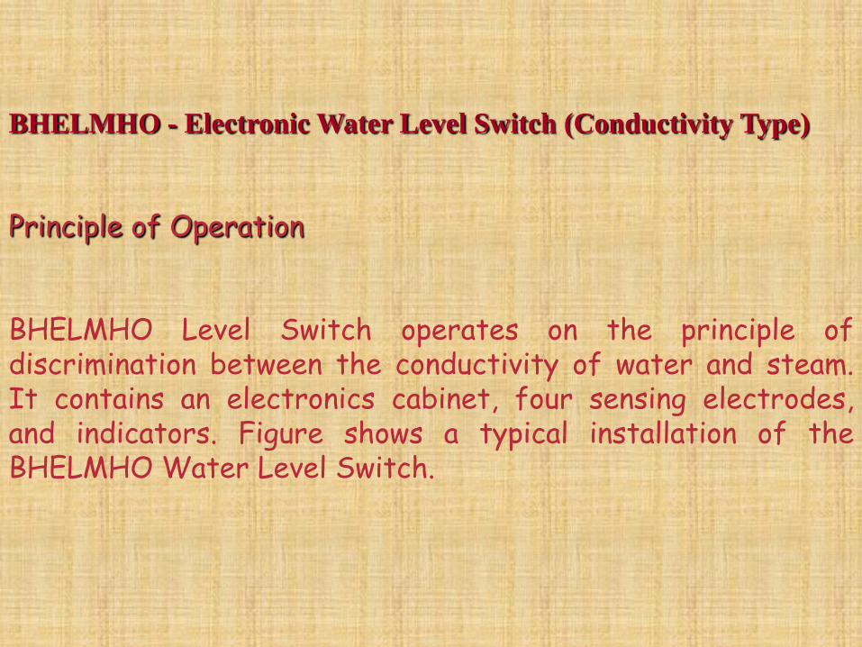
BHELMHO - Electronic Water Level Switch (Conductivity Type)
Principle of Operation
BHELMHO Level Switch operates on the principle ofdiscrimination between the conductivity of water and steam.It contains an electronics cabinet, four sensing electrodes,and indicators. Figure shows a typical installation of theBHELMHO Water Level Switch.

Functional Drawings of BHELMHO

Typical BHELMHO Level Switch Installation in HP Heater
A safe low excitation voltage is applied between the insulatedtip and the body of the sensing electrodes. The sensor outputgives a value for the conductance of the cell formed by theelectrode and the body, which is compared with a referencevalue and the electronic circuitry discriminates between steamand water. In addition the electronics is capable of detectingthe open and short fault conditions of the sensing system.
.

By the use of the proven conductivity techniqueBHELMHO Level Switch can be employed wherever waterlevel detection and monitoring is required, such as drainpots on steam lines or bled steam lines from turbines etc.The BHELMHO Level Switch with its self-checking, faulttolerant electronics with right level indication will bevery efficient in level monitoring.
BHELMHO Switch….Contd.

Areas of Application of BHELMHO in Power and Process Plants
De-aerator storage level
HP & LP Heater columns
Main boiler Drum Level
Blow down tank level
Main steam header drain
Hot and cold reheat drains
Turbine Extraction drain
Hot well alarms
Generator coolant level
Turbine casing drain

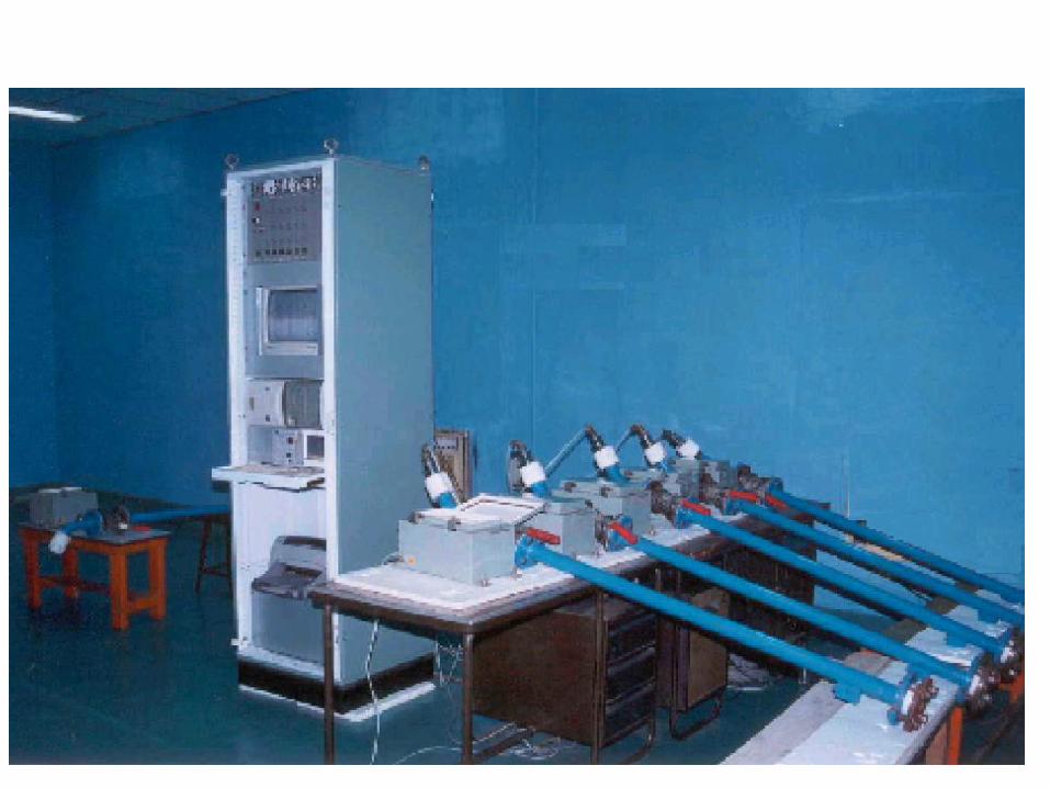
BHELSONIC
Sonic Tube Leak Detection System
Sonic Tube Leak Detection System (STLD) by BHEL(T) known as
“BHELSONIC” System is used in boilers to detect tube leakage in
the pressure parts region.”.

Sonic Tube Assembly

595
544
505
504
46.95
42.5
41.5
39.0
30.15
16.0
7
4
5
2
1
3
9
8
6
12
18
16
13
1012
14
15
17
LEFT SIDE FRONT SIDE LEFT SIDE
BHELSONIC System Sensor Locations (in a Typical 210 MW boilers)

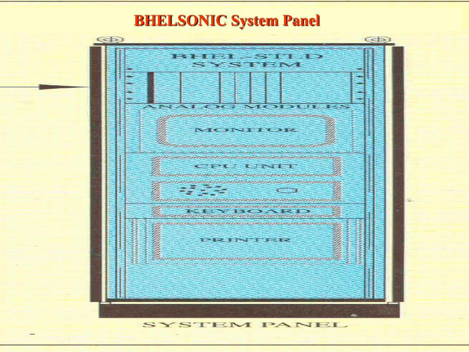
BHELSONIC System Panel

BHELFEED-
Microprocessor based
Gravimetric feeder control

Gravimetric Feeder – Overall view
Fdr photo-1

Solid State
Hard Wired
Feeder Electronics Roadmap by BHEL
16 Bit system
BHELFEED
8 Bit system
32 Bit system

Bharat Heavy Electricals Limited TIRUCHIRAPALLI
Committed to making a better world
Microprocessor based Gravimetric
feeder Control system
Coal conveyed :
= Weight x Belt speed
= Loadcell o/p x Tacho signal
MotorGear
Box
GFC
Controller
Signal
Conditioner
Speed
Controller
Load cellSignal
KBD & Display
TachoSignal
Demand Signal from
Combustion ControlOutput Signal
to Customer
Raw coal

Bharat Heavy Electricals Limited TIRUCHIRAPALLI
Committed to making a better world
MPGFC Panel
Easy integration with existing
feeders.
Suitable for VFD, ECC and DC
drives
Actual feed rate signal for DCS.
TCI pulse output.

Bharat Heavy Electricals Limited TIRUCHIRAPALLI
Committed to making a better world

Bharat Heavy Electricals Limited TIRUCHIRAPALLI
Committed to making a better world
Functional Features of MPGFC
Automatic calibration of Tare and Span.
Automatic tracking of Loadcell signals.
Auto change-over to Volumetric mode of operation
in case of loadcell signal faults.
Historic density calculation and record for use in
volumetric mode of operation.
Programming of specific feeder parameters.
Bharat Heavy Electricals Limited TIRUCHIRAPALLI
Committed to making a better world
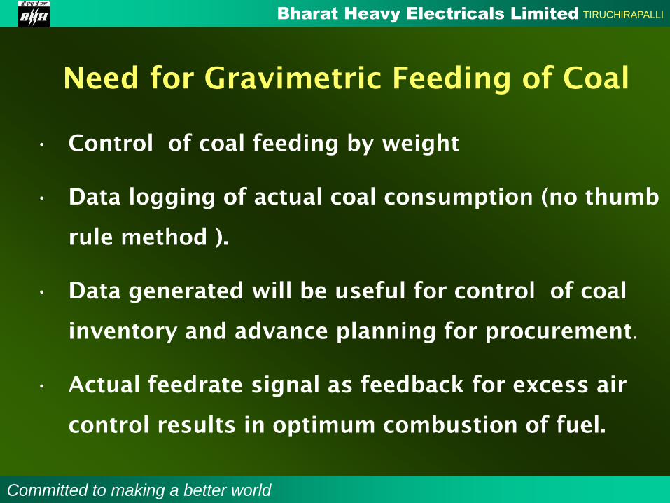
Need for Gravimetric Feeding of Coal
• Control of coal feeding by weight
• Data logging of actual coal consumption (no thumb
rule method ).
• Data generated will be useful for control of coal
inventory and advance planning for procurement.
• Actual feedrate signal as feedback for excess air
control results in optimum combustion of fuel.

Bharat Heavy Electricals Limited TIRUCHIRAPALLI
Committed to making a better world
Advanced Features of MPGFC
Advanced 32-bit Processor .
Highly integrated electronics with High
resolution ADC & DAC - Improved reliability
RTC for Date & Time stamp of events and data.
User friendly Keyboard.
Feeder status and alarm indicators
Contd..

Bharat Heavy Electricals Limited TIRUCHIRAPALLI
Committed to making a better world
Advanced Features of MPGFC
Vacuum Fluorescent Display 40 Ch x 2 line.
Self test and diagnostics.
Real time multimode data logging for coal
consumption.
Digital Totalizer for multimode mode operation.
Contd..

DESCRIPTION BHELFEED IMPORTED
CONTROL ARCHITECTURE 32 bit Microprocessor based 16 bit Microcontroller based
ELECTRONICS Modular construction Non modular
I / O MODULES Hot Swap Possible Hot Swap Not possible
BELT SLIPPAGE DETECTION Inbuilt with the system Separate unit required
TIMING FUNCTION FOR LOGIC Implemented in software Hardwired timers used
SERVICING OF ELECTRONIC
MODULES
Component level possible –
Economical
Board level only possible –
Expensive
RESPONSE TIME FOR SERVICING Immediate More due to re-export
COST OF SPARES Economical Expensive
AESTHETICS Excellent - Rack mounted modules
and reduced interconnections
Door mounted boards &
interconnections
DIAGNOSTICSBetter Diagnostics.
Customized for Indian conditionStandard diagnostics

Customer
Appreciation
From
M/s APGENCO -
VTPS

BHELSCAN-
Microcontroller
based Flame Scanners

Block diagram of BHELSCAN
FOC
One corner
flame
2/4
Flame
Detect
Logic
Other corner
processor o/p
LBAHead
Electronic
s
ADC MC
U
O/P
to
FSS
S

BHELSCAN BHEL make indigenous

BHELSCAN System Electronic Module

Troubleshooting

•Inadequate cooling capacity
•Inadequate flow of cooling water and /or sample
•Excessive flow of sample
•Leakage’s in cooling & sampling lines
•Analysers starving due to inadequate sample flow
•Chocking of sample lines/ filters
•Chiller : Leakage of refrigerant gas
•Fluctuations in sample flow to analysers
•Quality of cooling waer
•Ignorance in understanding System function.
•Lack of training – steam power engg + instrumentation
•Lack of maintenance

Symptoms:
Trim and frequency lamps are on together. Card is sent into oscillation,Which causes
the flame relay on the lamp and meter card to change state rapidly. This causes the
relay to generate a humming noise.
Probable case : IC302(CD4011BD)
Symptoms:
Neither the frequency nor the trim lamps are “ON”
Probable case : IC303(CD4047BD)
Symptoms:
Trim lamp will not change its pulsing rate even with a change in the DIP switch setting.
Probable case : IC303(CD4047BD)
Symptoms:
Frequency lamp is always “ON”
Probable case: C301,C304, or C306 (luf@50V)capacitors can be checked in circuit with
an ohmmeter. Defective component will be shorted.
Symptoms:
Trim and frequency lamps alternate”ON” and “OFF” at the same rate.
Probable case:IC302(CD4011BD)
Safe Scan System Trouble Shooting (Frequency detection Module )

Symptoms:
Flame lamp will not respond:TP404 reads approximately ) Vdc.
Probable case:IC401(CD4011BD)normal condition with flame TP401, TP402~
10Vdc TP403~0Vdc TP404~10VdcFlame relay is energized
and flame lamp on.
Symptoms:
Needle on the meter is at the top of scale and the fault lamp is “ON”
Probable case : B + fuse
Symptoms:
Needle remains in the middle of the scale and frequency lamp
on the frequency detection card is “OFF”Intensity fault detection
card is “ON”.
Probable case : B- fuse
Safe Scan System Trouble Shooting (Lamp and Meter Module )