cient wireless hopping sensor relocation based on
TRANSCRIPT
electronics
Article
Energy-Efficient Wireless Hopping Sensor RelocationBased on Prediction of Terrain Conditions
Sooyeon Park 1 , Moonseong Kim 2 and Woochan Lee 1,*1 Department of Electrical Engineering, Incheon National University, Incheon 22012, Korea; [email protected] Department of Liberal Arts, Seoul Theological University, Bucheon 14754, Korea; [email protected]* Correspondence: [email protected]; Tel.: +82-32-835-8436
Received: 9 December 2019; Accepted: 26 December 2019; Published: 28 December 2019 �����������������
Abstract: It is inevitable for data collection that IoT sensors are distributed to interested areas.However, not only the proper placement of sensors, but also the replacement of sensors that haverun out of energy is very difficult. As a remedy, wireless charging systems for IoT sensors have beenresearched recently, but it is apparent that the availability of charging system is limited especiallyfor IoT sensors scattered in rugged terrain. Thus, it is important that the sensor relocation modelsto recover sensing holes employ energy-efficient scheme. While there are various methods in themobile model of wireless sensors, well-known wheel-based movements in rough areas are hard toachieve. Thus, research is ongoing in various areas of the hopping mobile model in which wirelesssensors jump. Many past studies about hopping sensor relocation assume that all sensor nodesare aware of entire network information throughout the network. These assumptions do not fitwell to the actual environment, and they are nothing but classical theoretical research. In addition,the physical environment (sand, mud, etc.) of the area in which the sensor is deployed can changefrom time to time. In this paper, we overcome the theoretical-based problems of the past researchesand propose a new realistic hopping sensor relocation protocol considering terrain conditions. Sincethe status of obstacles around the sensing hole is unknown, the success rate of the hopping sensorrelocation is used to predict the condition of the surrounding environment. Also, we are confidentthat our team is uniquely implementing OMNeT++ (Objective Modular Network Testbed in C++)simulation in the hopping sensor relocation protocol to reflect the actual communication environment.Simulations have been performed on various obstacles for performance evaluation and analysis, andwe are confident that better energy efficiency with later appearance of sensing holes can be achievedcompared to well-known relocation protocols.
Keywords: mobile sensor; hopping sensor; relocation protocol; energy efficient protocol; internet ofthings (IoTs); wireless sensor networks (WSNs); simulation
1. Introduction
Recently, there have been active studies for big data analysis using networking to collect, process,and analyze a large amount of data [1]. In order to not only collect various data but also fast processinformation, the technologies of collecting and transmitting data have emerged as a very importantissue. Here, there is no doubt that the transmission technology among wireless sensors is importantfor big data technology. Research on various wireless sensor networking technologies to transmit thecollected data has been actively conducted for decades [2,3].
A lot of wireless sensors are properly distributed through the observation area to collect theinterested data [4,5]. It is not difficult to distribute the sensors to accessible areas to human, howeverunmanned mobile devices (unmanned air vehicle, drone, etc.) could be used in large inaccessible areas.After deploying the sensors, let us consider that data collection occurs frequently in particular area.
Electronics 2020, 9, 49; doi:10.3390/electronics9010049 www.mdpi.com/journal/electronics
Electronics 2020, 9, 49 2 of 17
There is an inherent problem that a small sensor has limited energy. To remedy this power limitation,wireless charging systems for IoT sensors have been researched actively recently [6]. However, chargingsystem for the sensors is not always available, especially in inaccessible area like rugged terrain. Thus,it is necessary that the sensor relocation protocol to recover sensing hole employs energy efficientscheme as a preemptive measure. Some sensors may be quickly drained of energy while continuouslycollecting and transmitting data in the particular area. This case is called a sensor node failure,the communication of the entire network may be disconnected, and the desired data could not becollected in the worst case. The particular area, where a certain number of sensors become faulted andcannot collect the interested data anymore, is called as a sensing hole [7]. In order to prevent a sensinghole occurred, various studies such as schemes of minimizing energy consumption by adjusting theactive/idle states and energy efficient routing protocols have been conducted [8–10]. Although theenergy limit of the sensor node can be reduced by various applications, it is impossible to solve thesensor node failure problem completely. Therefore, it is necessary to recover it by moving other sensorsto the sensing hole occurred, as the most realistic solution. For this reason, researches on mobile sensorshave received a lot of attention. The failure sensors depleted of energy could be replaced by mobilesensors moved from other area. The authors of [11] considered a case that a wheel-based mobile nodecould temporarily replace the role of a fixed node by moving if a fixed sensor node is failed in theinterested area. However, there are limitations in the migration of wheel-based sensors. In other words,energy consumption has to be further considered in order to move, however wheel-based movementis essentially inadequate in very rough areas.
In order to overcome the limitation of wheel-based mobility, a hopping-based moving model isintroduced. A hopping-based sensor node is bionically designed to jump itself, like a frog. For example,a mobile unit implemented by DARPA (Defense Advanced Research Projects Agency, USA) is able todo up to 100 jumps with one full fuel injection and jump up to 10 m high [12,13]. The paper [14] byMSU (Michigan State University, USA) describes the performance comparisons for the maximum jumpheight, jumping distance, and so on for various jumping robots, in detail. Researches on not only theimplementation of jump-based mobility but hopping sensor relocation algorithm to recover the sensingholes that occurred, have been actively conducted [15–18]. However, most of studies so far requirethat every cluster header sensor node has to know all information for the current whole network areaand set up routes to supply/request hopping sensors to recover sensing holes occurred. In fact, nomatter how small the observation field to obtain interested data is, the exchange of information andestablishment of paths among the cluster header sensors are difficult in real world, and involve a stormof numerous control messages. Recently, our research team has solved these problems drastically [19].First of all, every cluster header does not need to know all information of other cluster headers orall networks. It is a distributed networking-based relocation protocol that recovers a sensing holeby simply requesting necessary sensor nodes from neighbor cluster headers. A cluster header nodeselects appropriate hopping sensors based on information communicated among all sensor nodes inits cluster, and they are moved to the requesting neighbor cluster. Up to now, however, most relocationprotocols have assumed that the observation fields, in which mobile sensors are scattered, are idealenvironments. In other words, the areas where sensors move are likely to be irregular, under theexistence of obstacles like stones or mud. Reference [18] is the first study of hopping sensor relocationbased on probabilities of existence of obstacles, however there is a limitation that the assumption thatevery cluster header sensor grasps all information of rugged terrains in all regions is not very realistic.
In this paper, a novel relocation protocol that considers the probabilities of the level of obstaclesusing the information of success rate for migration is proposed. Here, it is not necessary for eachcluster header sensor node to know all information of entire network; the cluster header only knowsthe information such as the probabilities between neighbor clusters. In addition, as far as we know,it can be very meaningful to have the first realistic simulation with OMNeT++ [20], similar to theactual environment.

Electronics 2020, 9, 49 3 of 17
The rest of this paper is organized as follows. Section 2 summarizes the mobility model of hoppingsensor and the related relocation protocol. In Section 3, the proposed relocation protocol is explainedalong with the scenario in detail. The simulation results are analyzed in Section 4, and Section 5concludes this paper.
2. Previous Work
2.1. Characteristics and Movement Models of Hopping Sensors
Typical mobile sensors are based on wheels. This structure has the disadvantage that it is verydifficult to move in rough terrain such as gravel, sand, and so on. In order to overcome the mobilityproblem, hopping sensors that mimic movements such as a grasshopper or a frog have been devised.In addition, the hopping sensor enables communication among sensor nodes in environments where itis difficult for a sensor to communicate each other because the distance between sensor nodes is fartherthan a normal communication radius of a sensor, or where there are various obstacles which blockcommunication propagation. Up to now, various researchers have shown that the connectivity betweenhopping sensors could be improved by the jumping of each hopping sensor. The papers [21,22] haveshown that the communication radius is increased about six times compared to the one on the groundwhen a hopping sensor jumps 1 m from the ground. The paper [23] actually implemented a hoppingsensor using a separate launcher for jumping and measured the transmission radius varied accordingto the height of the jump. The changed transmission radii were compared with the results of [21], andit was confirmed that they had similar results.
Compared to a wheel-based sensor node, a hopping sensor, which is moving on jump, mightbe inherently less accurate to migrate to the desired area. In fact, it would be more desirable tohave a positive explanation for enabling movement in an environment that cannot be moved withwheels, rather than a negative idea that movement accuracy is poor. The paper [15] first attempted aperformance analysis of how a hopping sensor node was affected by wind when jumping and moving.It is obvious that the movement of hopping model is more vulnerable to air resistance than that ofwheel-based model. Mathematical modeling of this hopping movement can be explained as follows.
As shown in Figure 1, the hopping sensor does not land exactly the targeted location (T) afterjumping, and it is more likely to land near it (i.e., actual landing location; L). Let the variables Tand L be vectors of the target and actual landing locations. The error vector D with respect to thedifference between the locations can be expressed as L − T. Here, we assume that D follows thetwo-dimensional standard normal distribution with means (0, 0), standard deviations (σx, σy), andcorrelation ρ. The probability density function can be defined as
fXY =1
2πσxσy√
1− ρ2e−
12 (1−ρ2)
( x2
σ2x+
y2
σ2y−
2ρxyσxσy )
(1)
Let us consider that the hopping range is 2, standard deviations are 0.3, and the correlation iszero. The movement of the hopping sensor is as shown in Figure 1. The movement of the red circle isan ideal movement, but the movement of the blue circle is a movement that reflects the mentionedconstraints. It can be easily seen that the movement of the blue circle more appropriately reflects themovement in rough environment suitable for the hopping sensor than that of the red circle. Therefore,the above error vector of the movement would be preferably applied to the simulation in Section 4.

Electronics 2020, 9, 49 4 of 17Electronics 2020, 9, x FOR PEER REVIEW 4 of 16
Figure 1. An example of the movement of a hopping sensor considering movement-error.
2.2. Basic Assumptions about Hopping Sensors and Relocation Protocol
In the traditional research fields of wireless sensor networks (WSNs), there are various methods for clustering and cluster header selection of sensor nodes randomly distributed in the interested areas [24]. In fact, since the purpose of this paper is to study the relocation of hopping sensor nodes, it is assumed that the clustering and selection of the cluster headers have already been completed by various existing methods. For example, hopping sensor nodes are randomly scattered firstly on the interested area in which we want to collect data. After that, the area is divided by an appropriate clustering algorithm, and a cluster header node is selected for each cluster zone. The cluster header periodically communicates with member sensor nodes in its cluster zone, and it manages representative information of each member. Considering the network connectivity problem, communication between each cluster header and all member sensor nodes could jump to send and receive messages with its maximum transmission radius. Moreover, every hopping sensor node contains a GPS unit capable of knowing its current location [25].
The terms used in this paper are explained in Figure 2. Every hopping sensor node can be either a cluster header node or a member sensor node. Since the maximum transmission radius is defined as a cluster zone when the cluster header maximally jumps, there is a high possibility that direct communication between the cluster headers could be impossible. However, some member sensor nodes in the area intersecting with the cluster zones (that is, near the maximum transmission radius of each cluster header) may communicate with two or more cluster headers. This hopping sensor node is called as a relay node, and the role of the node could help to facilitate communication between cluster headers [18].
Figure 2. The defined terms for hopping sensor network.
Figure 1. An example of the movement of a hopping sensor considering movement-error.
2.2. Basic Assumptions about Hopping Sensors and Relocation Protocol
In the traditional research fields of wireless sensor networks (WSNs), there are various methodsfor clustering and cluster header selection of sensor nodes randomly distributed in the interestedareas [24]. In fact, since the purpose of this paper is to study the relocation of hopping sensor nodes,it is assumed that the clustering and selection of the cluster headers have already been completed byvarious existing methods. For example, hopping sensor nodes are randomly scattered firstly on theinterested area in which we want to collect data. After that, the area is divided by an appropriateclustering algorithm, and a cluster header node is selected for each cluster zone. The cluster headerperiodically communicates with member sensor nodes in its cluster zone, and it manages representativeinformation of each member. Considering the network connectivity problem, communication betweeneach cluster header and all member sensor nodes could jump to send and receive messages with itsmaximum transmission radius. Moreover, every hopping sensor node contains a GPS unit capable ofknowing its current location [25].
The terms used in this paper are explained in Figure 2. Every hopping sensor node can be either acluster header node or a member sensor node. Since the maximum transmission radius is definedas a cluster zone when the cluster header maximally jumps, there is a high possibility that directcommunication between the cluster headers could be impossible. However, some member sensornodes in the area intersecting with the cluster zones (that is, near the maximum transmission radius ofeach cluster header) may communicate with two or more cluster headers. This hopping sensor node iscalled as a relay node, and the role of the node could help to facilitate communication between clusterheaders [18].
Electronics 2020, 9, x FOR PEER REVIEW 4 of 16
Figure 1. An example of the movement of a hopping sensor considering movement-error.
2.2. Basic Assumptions about Hopping Sensors and Relocation Protocol
In the traditional research fields of wireless sensor networks (WSNs), there are various methods for clustering and cluster header selection of sensor nodes randomly distributed in the interested areas [24]. In fact, since the purpose of this paper is to study the relocation of hopping sensor nodes, it is assumed that the clustering and selection of the cluster headers have already been completed by various existing methods. For example, hopping sensor nodes are randomly scattered firstly on the interested area in which we want to collect data. After that, the area is divided by an appropriate clustering algorithm, and a cluster header node is selected for each cluster zone. The cluster header periodically communicates with member sensor nodes in its cluster zone, and it manages representative information of each member. Considering the network connectivity problem, communication between each cluster header and all member sensor nodes could jump to send and receive messages with its maximum transmission radius. Moreover, every hopping sensor node contains a GPS unit capable of knowing its current location [25].
The terms used in this paper are explained in Figure 2. Every hopping sensor node can be either a cluster header node or a member sensor node. Since the maximum transmission radius is defined as a cluster zone when the cluster header maximally jumps, there is a high possibility that direct communication between the cluster headers could be impossible. However, some member sensor nodes in the area intersecting with the cluster zones (that is, near the maximum transmission radius of each cluster header) may communicate with two or more cluster headers. This hopping sensor node is called as a relay node, and the role of the node could help to facilitate communication between cluster headers [18].
Figure 2. The defined terms for hopping sensor network.
Figure 2. The defined terms for hopping sensor network.

Electronics 2020, 9, 49 5 of 17
Unlike hopping sensor relocation protocols, which were only theoretically studied, the paper [19]proposed a relocation protocol suitable for a distributed environment so that it could be applied toa real environment. The protocol proposed in the mentioned paper is briefly summarized using anexample in Figure 3. If the cluster zone C is a sensing hole, the protocol strategy to recover the problemis as follows.
Electronics 2020, 9, x FOR PEER REVIEW 5 of 16
Unlike hopping sensor relocation protocols, which were only theoretically studied, the paper [19] proposed a relocation protocol suitable for a distributed environment so that it could be applied to a real environment. The protocol proposed in the mentioned paper is briefly summarized using an example in Figure 3. If the cluster zone C is a sensing hole, the protocol strategy to recover the problem is as follows.
Step 1. The cluster header HC sends a REQ message requesting one hopping sensor to the relay node R2.
Step 2. The relay node R2 forwards the REQ message received from HC to the cluster header HB of the cluster zone B.
Step 3. The cluster header HB sends a MOVE message for moving to neighbor cluster zone C to the hopping sensor M3 selected as a moveable member in its zone B.
Step 4. At the same time, the cluster header HB predicts that its zone could also be a sensing hole, and it sends a REQ message for requesting one hopping sensor to relay node R1.
Step 5. The relay node R1 forwards the message REQ to its another cluster header HA.
Step 6. The cluster header HA chooses M2 among hopping member sensor nodes of its zone A in its zone and commands the movement. As a result, one sensor is properly allocated to each cluster zone, and the sensing zone (cluster zone C) could be recovered.
Figure 3. An example of recovering a sensing hole with cross-clusters.
3. The Proposed Relocation Protocol for Rugged Terrains
Although the distributed-based relocation protocol [19] has made up for the drawbacks of the previous central-based relocation protocols, questions still remain whether it is suitable for the real world. In fact, it should be noted that the environment in which hopping sensors are deployed would be different from the general terrain. In the relocation protocol [19], topographical information on obstacles around the cluster zones were not taken into account. The movement of hopping sensors fails due to obstacles and the relocation cannot satisfy the movement requested from the cluster header of sensing hole. Thus, the number of messages continuously requested may increase to overcome the persisting sensing hole. This could put a heavy load on the entire network, and it would be very negative in terms of energy. Therefore, we propose a relocation protocol for more realistic hopping sensor networks by indirectly predicting the topographic information around sensing holes.
3.1. Basic Operation of the Proposed Relocation Protocol
In this section, we propose a novel relocation protocol that takes into account the environment surrounding the sensing hole occurred. Figure 4 shows the message flows between hopping sensors that the types are cluster header, relay node, and member sensor node. The detailed formats of the
Figure 3. An example of recovering a sensing hole with cross-clusters.
Step 1. The cluster header HC sends a REQ message requesting one hopping sensor to the relaynode R2.
Step 2. The relay node R2 forwards the REQ message received from HC to the cluster header HB
of the cluster zone B.Step 3. The cluster header HB sends a MOVE message for moving to neighbor cluster zone C to
the hopping sensor M3 selected as a moveable member in its zone B.Step 4. At the same time, the cluster header HB predicts that its zone could also be a sensing hole,
and it sends a REQ message for requesting one hopping sensor to relay node R1.Step 5. The relay node R1 forwards the message REQ to its another cluster header HA.Step 6. The cluster header HA chooses M2 among hopping member sensor nodes of its zone A in
its zone and commands the movement. As a result, one sensor is properly allocated to each clusterzone, and the sensing zone (cluster zone C) could be recovered.
3. The Proposed Relocation Protocol for Rugged Terrains
Although the distributed-based relocation protocol [19] has made up for the drawbacks of theprevious central-based relocation protocols, questions still remain whether it is suitable for the realworld. In fact, it should be noted that the environment in which hopping sensors are deployed wouldbe different from the general terrain. In the relocation protocol [19], topographical information onobstacles around the cluster zones were not taken into account. The movement of hopping sensorsfails due to obstacles and the relocation cannot satisfy the movement requested from the cluster headerof sensing hole. Thus, the number of messages continuously requested may increase to overcomethe persisting sensing hole. This could put a heavy load on the entire network, and it would be verynegative in terms of energy. Therefore, we propose a relocation protocol for more realistic hoppingsensor networks by indirectly predicting the topographic information around sensing holes.
3.1. Basic Operation of the Proposed Relocation Protocol
In this section, we propose a novel relocation protocol that takes into account the environmentsurrounding the sensing hole occurred. Figure 4 shows the message flows between hopping sensorsthat the types are cluster header, relay node, and member sensor node. The detailed formats ofthe messages for the proposed relocation protocol and the message flows for each sensor node aredescribed in detail as follows.

Electronics 2020, 9, 49 6 of 17
Electronics 2020, 9, x FOR PEER REVIEW 6 of 16
messages for the proposed relocation protocol and the message flows for each sensor node are described in detail as follows.
Figure 4. Scenario and message flow diagram for describing the proposed protocol.
Step 1: The cluster header of the cluster zone A periodically broadcasts a HELLO message inside its zone to identify member sensor nodes. If a member node receives HELLO for the first time, the source address of the received HELLO message is memorized as its cluster header.
HELLO: = {message type, source address, destination address (broadcasting)}
Step 2: The member that received the HELLO message responds to the cluster header with a HELLO-ACK message to notify its health. If different HELLO messages are received from several cluster headers in Step 1, the member node is aware of that it has become a relay node for each cluster header. Thus, it also indicates whether a relay node or not, when the HELLO-ACK message is replied.
HELLO-ACK: = {message type, source address, destination address, relay node? (T/F)}
Step 3: The cluster header determines whether or not, currently, its zone is a sensing hole using the number of addresses of HELLO messages received. In the case of a sensing hole, the cluster header sends a relay message to all its relay nodes.
RELAY: = {message type, source address, destination address (multicasting)}
Step 4: As soon as the relay nodes receive the RELAY message, they send a RELAY-ACK message back to the cluster header. The cluster header may sequentially receive several RELAY-ACK messages. Among them, the relay node of the RELAY-ACK message, which is first received at the cluster header, is selected and other RELAY-ACK messages are ignored. Also, if a relay node overhears a RELAY-ACK message from another relay node while preparing to send a RELAY-ACK message, it immediately stops sending its message.
RELAY-ACK: = {message type, source address, destination address}
Step 5: So far, the cluster header is able to detect that a sensing hole has occurred (Step 3), and it could choose a relay node to forward a message to the neighbor cluster header for requesting member hopping sensor nodes needed (Step 4). Here, the required number of members is the difference (T-C) between the threshold value (T) to determine the sensing hole and the current number of members (C). However, the environment around the detected sensing hole may be rough terrain in reality, the sensing hole would continue because it might be high probability that the number of relocated hopping sensors is smaller than the requested number (T-C). Therefore, the cluster header checks the numbers of previously requested members and successfully moved members and calculates the movement success rate (p = number of members successfully moved/number of members requested)
Figure 4. Scenario and message flow diagram for describing the proposed protocol.
Step 1: The cluster header of the cluster zone A periodically broadcasts a HELLO messageinside its zone to identify member sensor nodes. If a member node receives HELLO for the first time,the source address of the received HELLO message is memorized as its cluster header.
HELLO: = {message type, source address, destination address (broadcasting)}
Step 2: The member that received the HELLO message responds to the cluster header with aHELLO-ACK message to notify its health. If different HELLO messages are received from severalcluster headers in Step 1, the member node is aware of that it has become a relay node for each clusterheader. Thus, it also indicates whether a relay node or not, when the HELLO-ACK message is replied.
HELLO-ACK: = {message type, source address, destination address, relay node? (T/F)}
Step 3: The cluster header determines whether or not, currently, its zone is a sensing hole usingthe number of addresses of HELLO messages received. In the case of a sensing hole, the cluster headersends a relay message to all its relay nodes.
RELAY: = {message type, source address, destination address (multicasting)}
Step 4: As soon as the relay nodes receive the RELAY message, they send a RELAY-ACK messageback to the cluster header. The cluster header may sequentially receive several RELAY-ACK messages.Among them, the relay node of the RELAY-ACK message, which is first received at the cluster header,is selected and other RELAY-ACK messages are ignored. Also, if a relay node overhears a RELAY-ACKmessage from another relay node while preparing to send a RELAY-ACK message, it immediatelystops sending its message.
RELAY-ACK: = {message type, source address, destination address}
Step 5: So far, the cluster header is able to detect that a sensing hole has occurred (Step 3), and itcould choose a relay node to forward a message to the neighbor cluster header for requesting memberhopping sensor nodes needed (Step 4). Here, the required number of members is the difference (T − C)between the threshold value (T) to determine the sensing hole and the current number of members

Electronics 2020, 9, 49 7 of 17
(C). However, the environment around the detected sensing hole may be rough terrain in reality,the sensing hole would continue because it might be high probability that the number of relocatedhopping sensors is smaller than the requested number (T − C). Therefore, the cluster header checksthe numbers of previously requested members and successfully moved members and calculates themovement success rate (p = number of members successfully moved/number of members requested)of the surrounding environment for the current cluster zone. Here, the number of requesting membersensors (cnt) that can overcome the sensing hole can be calculated as follows.
cnt: = Ceiling[(T − C) ∗ (1 + (1 − p))] (2)
The cluster header sends a REQ message to the selected relay node.
REQ: = {message type, source address, destination address, cnt, sensing hole address, sensing hole GPS info.}
Step 6: When the relay node receives the REQ message from the cluster header of the sensinghole occurred, it forwards the received REQ message to another cluster header. Here, the source anddestination addresses of the currently received REQ message are modified to its own address and theaddress of the another cluster header to be delivered, respectively.
Step 7: When the neighbor cluster header of the occurred sensing hole receives the REQ messageforwarded, it broadcasts an ADV message to determine movable member hopping sensor nodes amongthe current members in its zone.
ADV: = {message type, source address, destination address (broadcasting) }
Step 8: Each member node that receives the ADV message sends an ADV-ACK message containingits current physical information to the cluster header.
ADV-ACK:= {message type, source address, destination address, some info.}
Here, above ‘some info.’ indicates several type of information for relocation strategy [19], includingthe current energy state, capability of hopping movement, GPS coordinate information, etc.
Step 9: The cluster header receives ACK messages and selects the appropriately movable hoppingsensor nodes. Then, it sends MOVE message, which includes the location information about thesensing hole, to the hopping sensors selected.
ADV: = {message type, source address, destination address (multicasting),sensing hole address, sensing hole GPS info.}
Step 10: The member nodes receiving the MOVE message have to hop to the neighbor zone usingthe GPS information of the cluster header of the sensing hole. Here, as every hopping member istaking into account the usual transmission radius of the neighbor cluster header, it could calculate thecoordinates of where to move properly. Thus, each member hopping sensor node no longer moveswhen the member node has moved as desired location.
Step 11: As mentioned in Step 1, the cluster header of the sensing hole broadcasts a HELLOmessage at periodic times. After a predetermined time, when the relocated member sensor nodereceives the new HELLO message, the member updates its previous cluster header information asthe current one. If the relocated member sensor node receives multiple HELLO messages at this time,it would be changed to a relay node. In addition, each cluster header is able to update the currentmovement success rate p through the number of HELLO-ACK messages to properly reflect the levelof obstacles. All hopping sensors have modules that can perform Steps 1 to 11 independently. Each

Electronics 2020, 9, 49 8 of 17
module of a hopping sensor could be activated depending on whether it is currently playing a role of{cluster header, relay node, member sensor node}. This is summarized as follows.
Cluster header: = {Steps 1, 3, 5, 7, 9, 11}
Relay node: = {Steps 3, 4, 5, 6}
Member sensor node: = {Steps 2, 8, 10}
3.2. Descriptions of the Proposed Protocol
So far, most previous studies on hopping sensor relocation are central-based manner which eachcluster header know all network information, but this is not a very practical study. The research of [19]only conducted a distributed-based approach to consider the realistic environment, but it still failedto take into account the surrounding obstacle information. That is, it is important to consider theenvironment using hopping sensors, not using the wheel-based ones. The following examples ofsimple scenarios in Figure 5 are described to understand the difference between cases reflected thesurrounding obstacle information or not.
Electronics 2020, 9, x FOR PEER REVIEW 8 of 16
simple scenarios in Figure 5 are described to understand the difference between cases reflected the surrounding obstacle information or not.
(a) Sensor M1 of zone A is relocated to zone B (b) Two sensors are energy depletion
(c) Sensor M3 is failed to move due to obstacle (d) Sensor M4 is also failed to move due to obstacle
Figure 5. Examples of comparison between the previous and proposed relocations.
In Figure 5a, we assume that the cluster zone B has to maintain five member sensor nodes, except for the cluster header HB, for data collection. The cluster header determines that the sensing hole occurs when the number of members is smaller than 5. Here, the cluster zone B was a sensing hole due to a lack of one member (i.e., before moving M1). In order to recover the sensing hole, after the cluster header HB of zone B requests one member from zone A (the first REQ), the member sensor node M1 of zone A moves to zone B.
In the first scenario, let us consider the relocation of hopping sensors without taking into account obstacles as mentioned previous literatures. In Figure 5b, two member sensor nodes fail due to energy exhausted in the cluster zone B. The cluster header HB is aware of the state of sensing hole, and it requests two members from the neighbor cluster zone A (the second REQ). Two members, which were ordered to move to the cluster zone B, are moving as shown in Figure 5c. One member M2 is successfully moved to the cluster zone B, while the other M3 is failed to move due to obstacle. The cluster header of the cluster zone B perceives the state of sensing hole again, and it requests one member from the cluster zone A (the third REQ). In Figure 5d, since the selected member M4 fails to move because of unexpected obstacle, the cluster zone B is still a sensing hole. In order to overcome the sensing hole, the cluster header HB requests one member from the cluster zone A repeatedly (the fourth REQ). The member M5 is successfully moved, and the sensing hole is finally recovered.
In the second scenario, let us take into account the relocation based on probabilities of existence of obstacles. In Figure 5b, the cluster header HB should recognize the state of the sensing hole and request some members from the neighbor cluster zone A. First of all, let the initial value of the movement success rate p be 1. The success rate p is used to calculate the requested number of member sensors. According to Equation (2), the number of the requested members is 2, Ceiling[( 5 − 3 )*( 1 + (1 − 1) ) ], the cluster header HB requests two members from the cluster zone A (the second REQ). In Figure 5c, the cluster header HA commands two members to move to the cluster zone B. As described in the above first scenario, one member M2 moves successfully, but the other member M3 fails to move due
Figure 5. Examples of comparison between the previous and proposed relocations.
In Figure 5a, we assume that the cluster zone B has to maintain five member sensor nodes, exceptfor the cluster header HB, for data collection. The cluster header determines that the sensing holeoccurs when the number of members is smaller than 5. Here, the cluster zone B was a sensing hole dueto a lack of one member (i.e., before moving M1). In order to recover the sensing hole, after the clusterheader HB of zone B requests one member from zone A (the first REQ), the member sensor node M1 ofzone A moves to zone B.
In the first scenario, let us consider the relocation of hopping sensors without taking into accountobstacles as mentioned previous literatures. In Figure 5b, two member sensor nodes fail due to energy

Electronics 2020, 9, 49 9 of 17
exhausted in the cluster zone B. The cluster header HB is aware of the state of sensing hole, and itrequests two members from the neighbor cluster zone A (the second REQ). Two members, whichwere ordered to move to the cluster zone B, are moving as shown in Figure 5c. One member M2is successfully moved to the cluster zone B, while the other M3 is failed to move due to obstacle.The cluster header of the cluster zone B perceives the state of sensing hole again, and it requests onemember from the cluster zone A (the third REQ). In Figure 5d, since the selected member M4 fails tomove because of unexpected obstacle, the cluster zone B is still a sensing hole. In order to overcomethe sensing hole, the cluster header HB requests one member from the cluster zone A repeatedly (thefourth REQ). The member M5 is successfully moved, and the sensing hole is finally recovered.
In the second scenario, let us take into account the relocation based on probabilities of existence ofobstacles. In Figure 5b, the cluster header HB should recognize the state of the sensing hole and requestsome members from the neighbor cluster zone A. First of all, let the initial value of the movementsuccess rate p be 1. The success rate p is used to calculate the requested number of member sensors.According to Equation (2), the number of the requested members is 2, Ceiling[(5 − 3) ∗ (1 + (1 − 1))],the cluster header HB requests two members from the cluster zone A (the second REQ). In Figure 5c,the cluster header HA commands two members to move to the cluster zone B. As described in the abovefirst scenario, one member M2 moves successfully, but the other member M3 fails to move due to theobstacle. Thus, the cluster header HB updates the value of p as 1/2, and it is also aware of the sensinghole. The cluster HB calculates the number of requesting members using Equation (2), Ceiling[(5 − 4)∗ (1 + (1 − 1/2))], so two members are requested to the cluster HA (the third REQ). One of the twomembers of A, the member M3 fails to move to the zone B, as in the first previous scenario. However,the other member M2 can successfully move to the zone B to overcome the state of sensing hole.
As we are looking at the mentioned two scenarios, it might be thought that the probability ofsuccessful movement represents the state of obstacles between cluster zones. Therefore, it is a goodexample to see that the use of the above probability could reduce the number of request messages, whenthe cluster header of sensing hole is requesting members to the neighbor zones. Actually, the numberof REQ messages of the first scenario is greater than that of the second scenario.
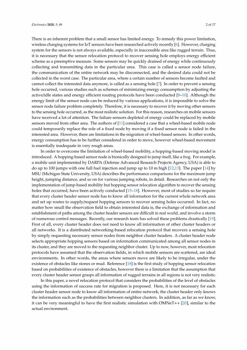
Message flow charts for the above described two scenarios could be explained easily, as shown inFigure 6. The cluster header HB of the zone B first detects its sensing hole occurred, and it transmits thefirst REQ message to the cluster header HA of the neighboring zone A, here the REQ includes that thenumber of member sensor node needed is one (i.e., cnt = 1). In fact, a direct communication betweenthe cluster headers is impossible, but for convenience, transmission and reception of their messageswith a RELAY node are omitted in the middle. The header HA selects M1 appropriately among itsmember nodes, and it sends a MOVE message to relocate to the sensing hole, zone B. Member nodeM1, which received MOVE, was able to recover the sensing hole without any problems for moving.
Electronics 2020, 9, 49 10 of 17Electronics 2020, 9, x FOR PEER REVIEW 10 of 16
(a) The previous relocation (b) The proposed relocation
Figure 6. Message flows for two scenarios. Figure 6. Message flows for two scenarios.
First, the message flows for the first scenario are depicted in Figure 6a. The cluster header ofB, HB, detects a sensing hole occurred again, and it sets two members (cnt = 2) for recovery in theREQ message, and sends the message (the second REQ) to the neighbor header HA. HA appropriately

Electronics 2020, 9, 49 11 of 17
selects two members (M2, M3) and transmits MOVE message to them to relocate, and the membernode M2 of them is moved to the zone B without any problems. However, the other member M3 is notable to move to the zone B due to an unexpected obstacle. After a certain time, the cluster header HB
determines that the sensing hole is not recovered. HB transmits a message (the third REQ) to requestone member needed to the zone A. HA directly sends MOVE message to the member M4, but M4unfortunately crashes into an obstacle and fails to recover the sensing hole. After a certain amountof time again, the header HB checks the current status of zone B, and it inserts that the value of cntis 1 (i.e., requires one member) in the requesting message and sends the message (the fourth REQ).The member M5 receiving MOVE from its cluster header HA successfully is moved to the sensing holezone B without colliding with obstacles.
Next, the message flows for the second scenario are depicted in Figure 6b. The header HB detectsa sensing hole occurred again and sends a message to request some hopping sensors. Here, HB
appropriately calculates the number of members required using that the movement success rate p isone and sets the value of cnt to two. HA chooses two members, M2 and M3, to transmit MOVE forrelocation, and then M2 is successfully moved to the neighbor zone B. However, another hoppingsensor M3 is unable to move because of unexpected obstacles. The cluster header HB determines thatthe sensing hole is not recovered after broadcasting HELLO message repeatedly. The header of zone Btransmits a message (the third REQ) to request some members needed from the header of zone A.
At this time, since the movement success rate for the previous REQ message is p = 1/2 (50%),the header of B could request two members calculated by Ceiling[(5 − 4) ∗ (1 + (1 − 1/2))], eventhough the zone B currently needs one member to recover the sensing hole. That is, HB recognizesthat the level of obstacles between cluster zones is high and requests a large number of sensors fromHA for rapid recovery. As expected, member M4 collided again with an obstacle, but member M5successfully moved to neighbor zone B. Since the proposed relocation protocol reduces the numberof REQ messages compared with the previous one, it could be verified that our protocol is energyefficient for wireless hopping sensor networks.
4. Simulation Results and Analysis
Unlike hopping sensor relocation studies so far, one of the most significant contributions thispaper is the use of OMNeT++ [26], which can realistically reflect wireless communications situationsin real-world environments. Table 1 describes the environment parameters used in the simulation forperformance evaluation.
Table 1. Simulation environments.
network area 250 m × 150 m
number of all member hopping sensor nodes 285
number of cluster headers 15
minimum number of members for each cluster to properly gather data(i.e., a sensing hole occurs if number of current members lower than the
value)10
the probability that an obstacle exists 0%, 1%, 2%, 3%
maximum communication radius for each sensor node 20 m
maximum communication radius when highly jumping 29 m
maximum distance that a sensor node moves forward with one jump 2 m
As shown in Figure 7, 285 hopping sensors are randomly scattered to the whole area of 250 m× 150 m to collect data. As mentioned in the previous Sections, since the aim of our research is notclustering techniques, we assume that the 15 cluster zones and headers are properly pre-set up in
Electronics 2020, 9, 49 12 of 17
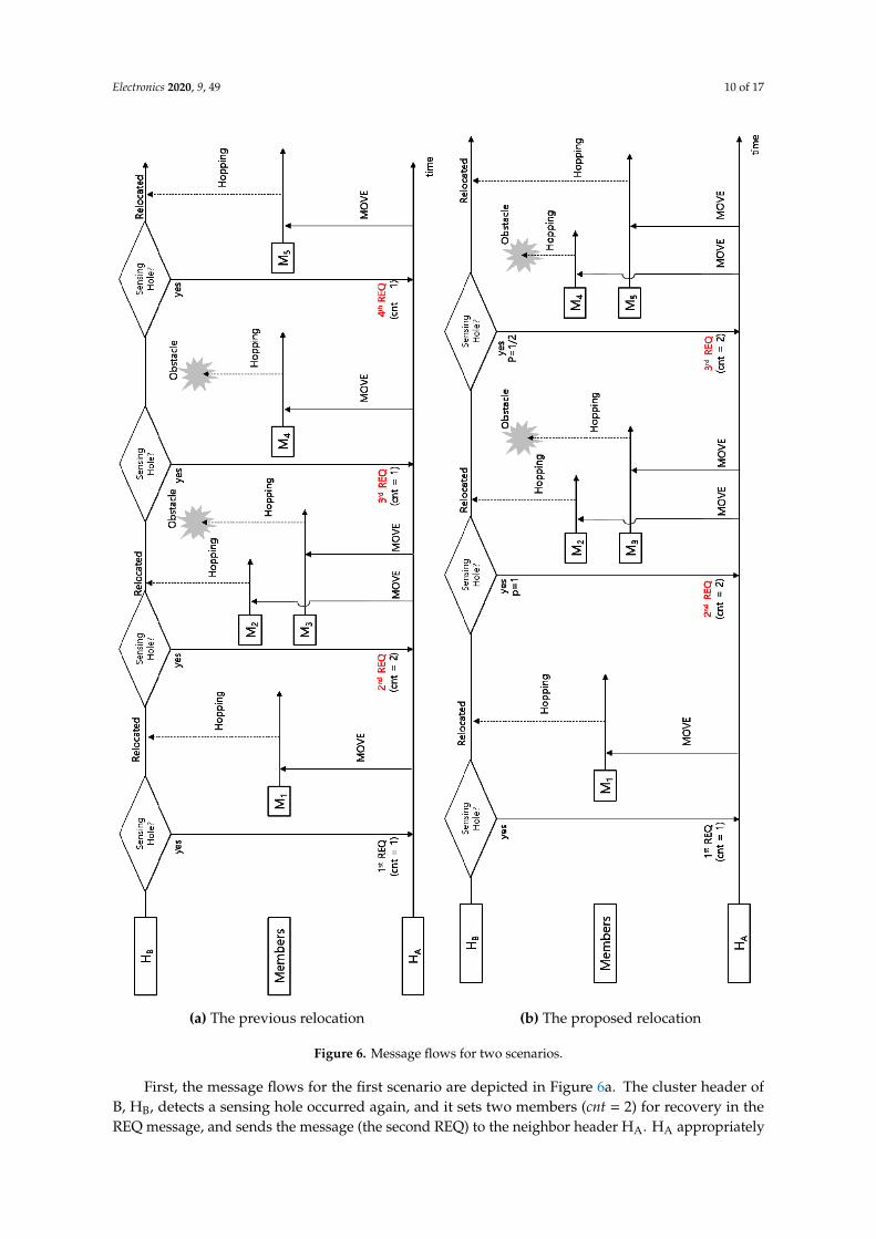
well-known ways. If there are fewer than 10 member sensor nodes in each cluster zone, excluding thecluster headers, the cluster header determines that its zone is a sensing hole.
Electronics 2020, 9, x FOR PEER REVIEW 12 of 16
nodes to recover the sensing hole occurred, sensor nodes in other zones are assumed to perform no data collection. It also indicates in yellow that a sensor has become faulted due to energy depletion after continuous data collection in Figure 7.
(a) legend (b) snapshot (obstacles 1%)
(c) snapshot (obstacles 2%) (d) snapshot (obstacles 3%)
Figure 7. Simulation snapshots for each environment.
In the majority of the hopping sensor relocation protocols so far, each sensor node knows all network information; like a central-based relocation protocol, it only considers the shortest path between cluster zones. However, it is very difficult to implement in reality; therefore, we propose a distributed-based relocation protocol, in order to overcome the drawbacks of the previous central-based relocation protocols. The implementation of the proposed protocol and simulation for performance evaluation are based on OMNeT++, which takes all communication system layers into account and also reflects both distributed computing of all sensors and actual environments. As far as we know, our implementation of hopping movement model considering obstacles is the first attempt in this field of study.
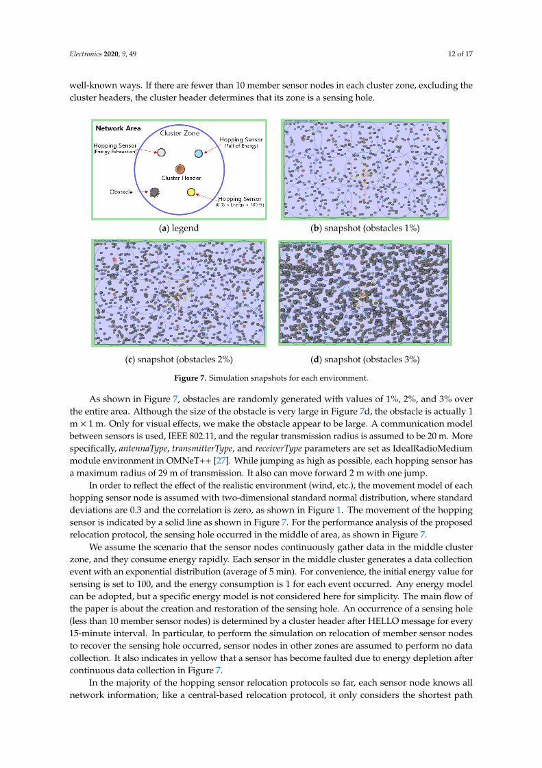
As previously explained, a sensing event occurs only in the middle cluster zone. After a three-day-long simulation, the result is shown in Figure 8. The dead member sensor node is colored yellow and the path of each hopping sensor is plotted by a solid line. Also, the movement of the sensor is shown as a zigzag due to environmental factors such as wind. It can also be confirmed that sensors captured in obstacles can no longer move and become faulted.
(a) obstacles 1% (b) obstacles 3%
Figure 8. Simulation snapshots finished for each obstacle.
Figure 7. Simulation snapshots for each environment.
As shown in Figure 7, obstacles are randomly generated with values of 1%, 2%, and 3% overthe entire area. Although the size of the obstacle is very large in Figure 7d, the obstacle is actually 1m × 1 m. Only for visual effects, we make the obstacle appear to be large. A communication modelbetween sensors is used, IEEE 802.11, and the regular transmission radius is assumed to be 20 m. Morespecifically, antennaType, transmitterType, and receiverType parameters are set as IdealRadioMediummodule environment in OMNeT++ [27]. While jumping as high as possible, each hopping sensor hasa maximum radius of 29 m of transmission. It also can move forward 2 m with one jump.
In order to reflect the effect of the realistic environment (wind, etc.), the movement model of eachhopping sensor node is assumed with two-dimensional standard normal distribution, where standarddeviations are 0.3 and the correlation is zero, as shown in Figure 1. The movement of the hoppingsensor is indicated by a solid line as shown in Figure 7. For the performance analysis of the proposedrelocation protocol, the sensing hole occurred in the middle of area, as shown in Figure 7.
We assume the scenario that the sensor nodes continuously gather data in the middle clusterzone, and they consume energy rapidly. Each sensor in the middle cluster generates a data collectionevent with an exponential distribution (average of 5 min). For convenience, the initial energy value forsensing is set to 100, and the energy consumption is 1 for each event occurred. Any energy modelcan be adopted, but a specific energy model is not considered here for simplicity. The main flow ofthe paper is about the creation and restoration of the sensing hole. An occurrence of a sensing hole(less than 10 member sensor nodes) is determined by a cluster header after HELLO message for every15-minute interval. In particular, to perform the simulation on relocation of member sensor nodesto recover the sensing hole occurred, sensor nodes in other zones are assumed to perform no datacollection. It also indicates in yellow that a sensor has become faulted due to energy depletion aftercontinuous data collection in Figure 7.
In the majority of the hopping sensor relocation protocols so far, each sensor node knows allnetwork information; like a central-based relocation protocol, it only considers the shortest path

Electronics 2020, 9, 49 13 of 17
between cluster zones. However, it is very difficult to implement in reality; therefore, we propose adistributed-based relocation protocol, in order to overcome the drawbacks of the previous central-basedrelocation protocols. The implementation of the proposed protocol and simulation for performanceevaluation are based on OMNeT++, which takes all communication system layers into account andalso reflects both distributed computing of all sensors and actual environments. As far as we know,our implementation of hopping movement model considering obstacles is the first attempt in this fieldof study.
As previously explained, a sensing event occurs only in the middle cluster zone. After athree-day-long simulation, the result is shown in Figure 8. The dead member sensor node is coloredyellow and the path of each hopping sensor is plotted by a solid line. Also, the movement of the sensoris shown as a zigzag due to environmental factors such as wind. It can also be confirmed that sensorscaptured in obstacles can no longer move and become faulted.
Electronics 2020, 9, x FOR PEER REVIEW 12 of 16
nodes to recover the sensing hole occurred, sensor nodes in other zones are assumed to perform no data collection. It also indicates in yellow that a sensor has become faulted due to energy depletion after continuous data collection in Figure 7.
(a) legend (b) snapshot (obstacles 1%)
(c) snapshot (obstacles 2%) (d) snapshot (obstacles 3%)
Figure 7. Simulation snapshots for each environment.
In the majority of the hopping sensor relocation protocols so far, each sensor node knows all network information; like a central-based relocation protocol, it only considers the shortest path between cluster zones. However, it is very difficult to implement in reality; therefore, we propose a distributed-based relocation protocol, in order to overcome the drawbacks of the previous central-based relocation protocols. The implementation of the proposed protocol and simulation for performance evaluation are based on OMNeT++, which takes all communication system layers into account and also reflects both distributed computing of all sensors and actual environments. As far as we know, our implementation of hopping movement model considering obstacles is the first attempt in this field of study.
As previously explained, a sensing event occurs only in the middle cluster zone. After a three-day-long simulation, the result is shown in Figure 8. The dead member sensor node is colored yellow and the path of each hopping sensor is plotted by a solid line. Also, the movement of the sensor is shown as a zigzag due to environmental factors such as wind. It can also be confirmed that sensors captured in obstacles can no longer move and become faulted.
(a) obstacles 1% (b) obstacles 3%
Figure 8. Simulation snapshots finished for each obstacle. Figure 8. Simulation snapshots finished for each obstacle.
We have simulated the relocation protocols using a sensor network topology generated randomly,and the results are described in Figures 9 and 10. First, Figure 9 shows the sensor retention rate in themiddle cluster. Since the minimum number of members for each cluster to properly gather data is 10,the sensor retention rate is 1 if there are more than 10 member sensor nodes. For example, if there arefive sensor nodes, the sensor retention rate is 0.5 (= 5/10), and if there is only one sensor, the sensorretention rate is 0.1. Since the previous hopping sensor relocation protocol [19] ignores the existence ofobstacles, the sensor retention rate of it tends to be much lower than that of the proposed protocol,as shown in Figure 9. Figure 9 shows the change of each sensor retention rate during about threedays. Since the sensing hole of the middle cluster occurs continuously, the neighbors’ cluster headersmight provide redundant sensors to recover the middle cluster’s sensing hole until around 1000 min.However, neighbors’ nodes are also depleted at that moment, thus the sensor retention rates in bothschemes start to drop as shown in the green circle of Figure 9a. The blue circle of Figure 9a indicatesthat the proposed method considering obstacles shows better retention rate than previous scheme.
Figure 9b illustrates the difference between the sensor retention rates of the proposed andthe previous protocols. It is easy to see that the number of top marks is more than that of belowmarks in Figure 9b. Since the sensor retention rates are only considered in the middle cluster zone,the denominator is ten, which is the minimum number of sensors to recover a sensing hole. In otherwords, if the difference of the rates is the positive 0.5, the proposed method accommodates five moresensors than the previous method at the same instance. A higher retention rate would result inrequesting a smaller number of sensors compared with another method and generating fewer messagesfor movements to neighboring cluster zones. Hence, the proposed scheme would consume smallerenergy to generate messages compared to the previous scheme and can play a major role in extendingthe lifetime of the network.

Electronics 2020, 9, 49 14 of 17
1
(a) obstacles 1%
(b) retention rate difference for (a)
(c) obstacles 2%
(d) obstacles 3%
Figure 9. Sensor retention rates at the middle cluster.
Specially, in Figure 9d of obstacles 3%, our protocol successfully recovers the sensing hole betterthan that of the previous one. In other words, it is possible to strongly predict that data collection couldbe better than the compared protocol, even if the cluster zone still cannot recover the sensing hole.
In the simulation, every HELLO message is periodically broadcasted by each cluster header.The interval is set to be 15 min, and the cluster header should determine whether or not its zone is asensing hole for every interval time. Whenever each cluster header checks the state of the sensinghole and sends REQ message, the moments for sensing hole appearance are shown in Figure 10.The delayed occurrence of sensing holes of this protocol compared to previous one indicates that moresuccessful data collection is achieved. In addition, as we mentioned earlier in the message flows,the short duration of each occurrence of the sensing hole means that numerous messages are generatedfor REQ throughout the entire network. This could lead to unnecessary energy consumption dueto message storms. Furthermore, in order to successfully accomplish the continuous desired datacorrection at the end of the wireless sensor network (i.e., the sink nodes), a relocation protocol has toavoid unnecessary energy consumption. Therefore, our relocation protocol is appropriate to reduceunnecessary energy consumption.
Electronics 2020, 9, 49 15 of 17
Electronics 2020, 9, x FOR PEER REVIEW 14 of 16
consume smaller energy to generate messages compared to the previous scheme and can play a major role in extending the lifetime of the network.
Specially, in Figure 9d of obstacles 3%, our protocol successfully recovers the sensing hole better than that of the previous one. In other words, it is possible to strongly predict that data collection could be better than the compared protocol, even if the cluster zone still cannot recover the sensing hole.
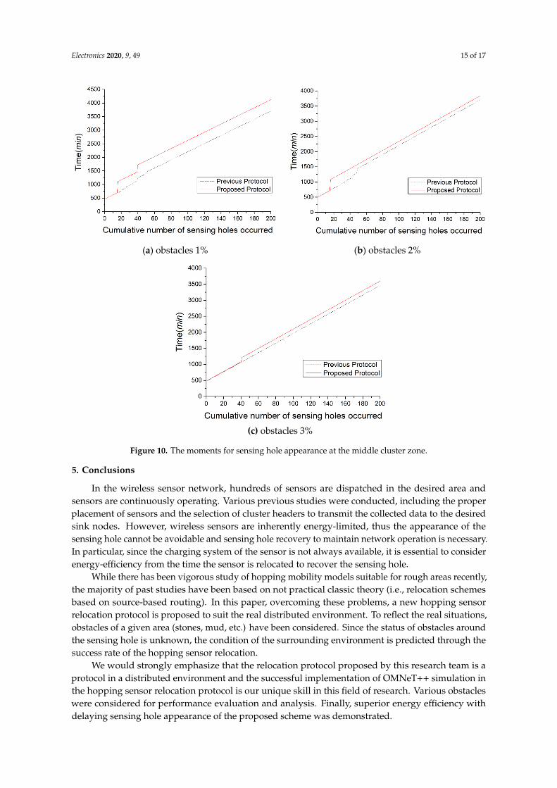
(a) obstacles 1%
(b) obstacles 2%
(c) obstacles 3%
Figure 10. The moments for sensing hole appearance at the middle cluster zone.
In the simulation, every HELLO message is periodically broadcasted by each cluster header. The interval is set to be 15 min, and the cluster header should determine whether or not its zone is a sensing hole for every interval time. Whenever each cluster header checks the state of the sensing hole and sends REQ message, the moments for sensing hole appearance are shown in Figure 10. The delayed occurrence of sensing holes of this protocol compared to previous one indicates that more successful data collection is achieved. In addition, as we mentioned earlier in the message flows, the short duration of each occurrence of the sensing hole means that numerous messages are generated for REQ throughout the entire network. This could lead to unnecessary energy consumption due to message storms. Furthermore, in order to successfully accomplish the continuous desired data correction at the end of the wireless sensor network (i.e., the sink nodes), a relocation protocol has to avoid unnecessary energy consumption. Therefore, our relocation protocol is appropriate to reduce unnecessary energy consumption.
5. Conclusion
Figure 10. The moments for sensing hole appearance at the middle cluster zone.
5. Conclusions
In the wireless sensor network, hundreds of sensors are dispatched in the desired area andsensors are continuously operating. Various previous studies were conducted, including the properplacement of sensors and the selection of cluster headers to transmit the collected data to the desiredsink nodes. However, wireless sensors are inherently energy-limited, thus the appearance of thesensing hole cannot be avoidable and sensing hole recovery to maintain network operation is necessary.In particular, since the charging system of the sensor is not always available, it is essential to considerenergy-efficiency from the time the sensor is relocated to recover the sensing hole.
While there has been vigorous study of hopping mobility models suitable for rough areas recently,the majority of past studies have been based on not practical classic theory (i.e., relocation schemesbased on source-based routing). In this paper, overcoming these problems, a new hopping sensorrelocation protocol is proposed to suit the real distributed environment. To reflect the real situations,obstacles of a given area (stones, mud, etc.) have been considered. Since the status of obstacles aroundthe sensing hole is unknown, the condition of the surrounding environment is predicted through thesuccess rate of the hopping sensor relocation.
We would strongly emphasize that the relocation protocol proposed by this research team is aprotocol in a distributed environment and the successful implementation of OMNeT++ simulation inthe hopping sensor relocation protocol is our unique skill in this field of research. Various obstacleswere considered for performance evaluation and analysis. Finally, superior energy efficiency withdelaying sensing hole appearance of the proposed scheme was demonstrated.

Electronics 2020, 9, 49 16 of 17
Author Contributions: S.P. and M.K. are the co-first authors and contributed equally. S.P., M.K., and W.L. designedthe protocol and the simulation process. S.P., M.K., and W.L. coordinated the grant funding, conducted the study,analyzed the data, and drafted the first version of the manuscript. The simulation was conducted by S.P. andM.K., and W.L. supervised the software development. All authors have read and agreed to the published versionof the manuscript.
Funding: This work was supported by Research Assistance Program (2019) in the Incheon National Universityand the National Research Foundation of Korea (NRF) grant funded by the Ministry of Science, ICT & FuturePlanning (No. NRF - 2019R1G1A1007832).
Conflicts of Interest: The authors declare no conflict of interest.
References
1. Yu, S.; Liu, M.; Dou, W.; Liu, X.; Zhou, S. Networking for Big Data: A Survey. IEEE Commun. Surv. Tutor.2017, 19, 531–549. [CrossRef]
2. Chen, M.; Mao, S.; Liu, Y. Big Data: A Survey. Mob. Netw. Appl. 2014, 19, 171–209. [CrossRef]3. Yaqoob, I.; Ahmed, E.; Hashem, I.A.T.; Ahmed, A.I.A.; Gani, A.; Imran, M.; Guizani, M. Internet of Things
Architecture: Recent Advances, Taxonomy, Requirements, and Open Challenges. IEEE Wirel. Commun. 2017,24, 10–16. [CrossRef]
4. Zhang, Y.; Xiong, Z.; Niyato, D.; Wang, P.; Kim, D.I. Toward a Perpetual IoT System: Wireless PowerManagement Policy With Threshold Structure. IEEE Internet Things J. 2018, 5, 5254–5270. [CrossRef]
5. Ray, P.P.; Mukherjee, M.; Shu, L. Internet of Things for Disaster Management: State-of-the-Art and Prospects.IEEE Access 2017, 5, 18818–18835. [CrossRef]
6. Chudzikiewicz, J.; Furtak, J.; Zielinski, Z. Fault-tolerant techniques for the Internet of Military Things.In Proceedings of the IEEE 2nd World Forum on Internet of Things (WF-IoT), Milan, Italy, 14–16 December2015; pp. 496–501.
7. Kosar, R.; Onur, E.; Ersoy, C. Redeployment Based Sensing Hole Mitigation in Wireless Sensor Networks.In Proceedings of the IEEE 2009 Wireless Communications and Networking Conference (WCNC), Budapest,Hungary, 5–8 April 2009.
8. Kim, M.; Park, S.; Lee, W. A Robust Energy Saving Data Dissemination Protocol for IoT-WSNs. In KSIITransactions on Internet and Information Systems (TIIS); 2018; pp. 5744–5764. [CrossRef]
9. Kim, M.; Jeong, E.; Bang, Y.-C.; Hwang, S.; Shin, C.; Jin, G.-J.; Kim, B. An Energy-aware Multipath RoutingAlgorithm in Wireless Sensor Networks. IEICE Trans. Inf. Syst. 2008, 91, 2419–2427. [CrossRef]
10. Elappila, M.; Chinara, S.; Parhi, D.R. Survivable Path Routing in WSN for IoT applications. Pervasive Mob.Comput. 2018, 43, 49–63. [CrossRef]
11. Luo, R.C.; Huang, J.-T.; Chen, O. A Triangular Selection Path Planning Method with Dead Reckoning Systemfor Wireless Mobile Sensor Mote. In Proceedings of the 2006 IEEE International Conference on Systems, Manand Cybernetics, Taipei, Taiwan, 8–11 October 2006; pp. 162–168.
12. Chellappan, S.; Snyder, M.E.; Thakur, M. Distributed exploratory coverage with limited mobility. Int. J.Space-Based Situated Comput. 2014, 4, 114–124. [CrossRef]
13. Snyder, M.E. Foundations of Coverage Algorithms in Autonomic Mobile Sensor Networks. Ph.D. Thesis,Missouri University of Science and Technology, Rolla, MO, USA, 2014.
14. Zhao, J.; Xu, J.; Gao, B.; Xi, N.; Cintrón, F.J.; Mutka, M.W.; Xiao, L. MSU Jumper: A Single-Motor-ActuatedMiniature Steerable Jumping Robot. IEEE Trans. Robot. 2013, 29, 602–614. [CrossRef]
15. Cen, Z.; Mutka, M.W. Relocation of Hopping Sensors. In Proceedings of the IEEE International Conferenceon Robotics and Automation (ICRA 08), Pasadena, CA, USA, 19–23 May 2008; pp. 569–574.
16. Kim, M.; Mutka, M.W. On Relocation of Hopping Sensors for Balanced Migration Distribution of Sensors; Springer:Berlin, Heidelberg, 2009; pp. 361–371.
17. Kim, M.; Mutka, M.W. Multipath-based Relocation Schemes Considering Balanced Assignment for HoppingSensors. In Proceedings of the IEEE/RSJ International Conference on Intelligent Robots and Systems (IROS 09),St. Louis, MO, USA, 10–15 October 2009; pp. 5095–5100.
18. Kim, M.; Mutka, M.W.; Choo, H. On Relocation of Hopping Sensors for Rugged Terrains. In Proceedings ofthe IEEE International Conference on Computational Sciences and its Applications (ICCSA 10), Fukuoka,Japan, 23–26 March 2010; pp. 203–210.
Electronics 2020, 9, 49 17 of 17
19. Kim, M.; Park, S.; Lee, W. Energy and Distance-Aware Hopping Sensor Relocation for Wireless SensorNetworks. Sensors 2019, 19, 1567. [CrossRef] [PubMed]
20. OMNeT Web Site. Available online: https://www.omnetpp.org (accessed on 9 December 2019).21. Cintr’on, F.; Pongaliur, K.; Mutka, M.W.; Xiao, L.; Zhao, J.; Xi, N. Leveraging height in a jumping sensor
network to extend network coverage. IEEE Trans. Wirel. Commun. 2012, 11, 1840–1849. [CrossRef]22. Cintr’on, F. Network Issues for 3D Wireless Sensors Networks. Ph.D. Thesis, Michigan State University,
East Lansing, MI, USA, 2013.23. Kim, M.; Kim, T.; Shon, M.; Kim, M.; Choo, H. Design of a Transmission Process for Hopping Sensors to
Enhance Coverage. In Proceedings of the International Conference Wireless Networks (ICWN 10), Las Vegas,NV, USA, 12–15 July 2010; pp. 377–382.
24. Rostami, A.S.; Badkoobe, M.; Mohanna, F.; Keshavarz, H.; Hosseinabadi, A.A.R.; Sangaiah, A.K. Survey onclustering in heterogeneous and homogeneous wireless sensor networks. J. Supercomput. 2018, 74, 277–323.[CrossRef]
25. Sabor, N.; Sasaki, S.; Abo-Zahhad, M.; Ahmed, S.M. A Comprehensive Survey on Hierarchical-BasedRouting Protocols for Mobile Wireless Sensor Networks: Review, Taxonomy, and Future Directions, Hindawi.Wirel. Commun. Mob. Comput. 2017, 2017, 23. [CrossRef]
26. Zarrad, A.; Alsmadi, I. Evaluating network test scenarios for network simulators systems. International J.Distrib. Sens. Netw. 2017, 13, 1550147717738216. [CrossRef]
27. Virdis, A.; Kirsche, M. Recent Advances in Network Simulation: The OMNeT++ Environment and Its Ecosystem;Springer: Cham, Switzerland, 2019. [CrossRef]
© 2019 by the authors. Licensee MDPI, Basel, Switzerland. This article is an open accessarticle distributed under the terms and conditions of the Creative Commons Attribution(CC BY) license (http://creativecommons.org/licenses/by/4.0/).