ciers course introduction · ciers-ga-lab01-ak ciers course introduction . the following graded...
TRANSCRIPT
CIERS-GA-LAB01-AK
CIERS Course Introduction The following graded assessment lab measures one’s ability to perform CCIE style problems under time pressure situations. The tasks presented in this lab will require carefully performed issue spotting and options analysis. Furthermore, one must rigorously verify all tasks performed. All of these tasks must be performed within a finite period of time. After completing the lab, a detailed answer key will be supplied along with access to a SHOWiT repository that represents the complete state of the pod at the end of the lab. Each Graded Assessment Lab user can compare his or her personal SHOWiT output with the SHOWiT output generated for the Master.
Graded Assessment Lab CIERS-GA-LAB01 Answer Key
2 CIERS Graded Assessment Labs v1.0 © 2008 Cisco CCIEXcel Pilot Program
Table of Contents
CIERS Course Introduction ...................................................................................................... 1 Graded Assessment Lab CIERS-GA-LAB01 Answer Key .............................................................. 1
Disclaimer ....................................................................................................................................................... 3 Cisco Non-Disclosure Agreement Compliance .............................................................................................. 3 Answer Key Structure ..................................................................................................................................... 3
Section One: ............................................................................................................................................ 3 Section Two: ............................................................................................................................................ 3
CIERS-GA-LAB01 Answer Key ......................................................................................................... 4 Grading and Duration ..................................................................................................................................... 4 Restrictions and Goals ................................................................................................................................... 4 Explanation of Each of the Restrictions and Goals ........................................................................................ 5
1. Frame Relay and Serial Communications Section ..................................................................................... 6 2. Catalyst Switch Configuration Section ........................................................................................................ 8 3. IPv4 OSPF Section .................................................................................................................................. 16 4. IPv4 EIGRP Section ................................................................................................................................. 21 5. IPv4 RIP ................................................................................................................................................... 23 6. IPv4 Redistribution Section ...................................................................................................................... 26 7. Border Gateway Protocol Section ............................................................................................................ 27 8. IPv6 Routing Section ................................................................................................................................ 31 9. QOS Section ............................................................................................................................................ 34 10. Security Section ..................................................................................................................................... 39 11. Address Administration Section .............................................................................................................. 40 12. Gateway Redundancy Section ............................................................................................................... 41 13. Multicast Section .................................................................................................................................... 42 14. Traffic Control Section ............................................................................................................................ 45

© 2008 Cisco CCIExcel Pilot Program CIERS Course Introduction 3
Disclaimer NetMasterClass, LLC is an independent training and consulting company based in Herndon, Virginia. The terms “Cisco”, “Cisco Systems” and “CCIE” are the trademarks of Cisco Systems, Inc. NetMasterClass, LLC is Cisco Learning Partner Text
Cisco Non-Disclosure Agreement Compliance All products and services offered by NetMasterClass, LLC are in full compliance with the Cisco CCIE Lab non-disclosure agreement. The content of the NetMasterClass CCIE preparation materials is based upon the NetMasterClass “issue spotting and analysis” internetwork training methods Text
Answer Key Structure
Section One:
The original exam with highlighted notes on the hidden issues the test taker should have spotted and the tasks the test taker should have performed. When you read through this section, make note of the bolded and italicized statements in the tasks of the original assessment exam. They are bolded and italicized to emphasize their inclusion of a hidden issue that you should have spotted.
Section Two:
To obtain a comprehensive view of the configuration for specific section, access the SHOWiT engine. With the SHOWiT engine, you can enter in over 1000 IOS commands as well a collection of NMC proprietary commands such as “show all”.
4 CIERS Graded Assessment Labs v1.0 © 2008 Cisco CCIEXcel Pilot Program
CIERS-GA-LAB01 Answer Key
Caution REGARDLESS OF ANY CONFIGURATION YOU PERFORM IN THIS EXAM, IT IS VERY IMPORTANT TO CONFORM TO THE GENERAL GUIDELINES PROVIDED BELOW. IF YOU DO NOT CONFORM TO THEM, THIS CAN RESULT IN A SIGNIFICANT DEDUCTION OF POINTS IN YOUR FINAL EXAM SCORE.
Grading and Duration
Lab duration - hours: 8 Maximum score - points: 100 Minimum passing score - points: 80
Restrictions and Goals
Caution Read this section carefully!
In order to receive any credit for a subsection you must fully complete the subsection as per requirements. There is no partial credit for the subsections.
IP subnets on the diagram belong to network 131.10.0.0/16.
Do not introduce any new IP addresses, use only IP addresses specified in the scenario.
Static IPv4 and IPv6 routes are not allowed in this exercise.
Advertise IPv4 and IPv6 Loopback interfaces with their original masks.
The Backbone Router BB is reachable via 150.100.10.110.
Do not configure Policy Based Routing (PBR).
All IPv4 IP addresses involved in this scenario must be reachable, except for the prefixes advertised from the backbone and interfaces connected to the shared equipment.
“N” represents the group number, “X” represents the pod number. Check your on-line instructions for your number “NX”. Failure to assign the correct IP address could result in losing points in multiple sections.
DO NOT modify the hostname, console or VTY configuration unless it specified otherwise.
DO NOT modify the initial interface or IP address numbering.

© 2008 Cisco CCIExcel Pilot Program CIERS Course Introduction 5
Explanation of Each of the Restrictions and Goals IP subnets in the Scenario diagram belong to network 131.10.0.0/16 The third and forth octets of the IP addresses displayed on the diagram belong to 131.10.0.0/16, unless specified otherwise. Do not use any static routes. Static routes can be used to solve a range of reachability problems. However, you cannot use them. You must rely on skillful configuration of all your unicast routing protocols. Make sure all IPv4 and IPv6 loopback interfaces are advertised with their original masks, unless noted otherwise. This requirement is primarily for the OSPF advertised loopbacks. Use “ip ospf network point-to-point” under the loopback interface. Otherwise, the loopback will be advertised as a /32 or /128 host entry by default. Make sure all IP interfaces in the diagram are reachable within this internetwork. This is a key goal to observe. This requires that all of your IGPs are configured properly. Also, all of your routing policy tasks must be configured properly. The key elements of your routing policy include route redistribution and the controlling of routing updates using distribute-lists, route-maps and the distance command. You must perform redistribution in order to assure that all IP addresses are reachable without the use of static routes. Networks received from the backbone routers and networks connected to shared equipment are excluded from the reachability requirement, as well as networks advertised in the BGP section. You are not required to make backbone prefixes reachable from all routers in your pod. Also, prefixes advertised via BGP need not necessarily be reachable from non-BGP speaking routers in you pod. Do not modify the hostname, console and vty configuration, initial interface and IP address numbering. Follow the numbering conventions carefully.

6 CIERS Graded Assessment Labs v1.0 © 2008 Cisco CCIEXcel Pilot Program
1. Frame Relay and Serial Communications Section Issue: Configure Frame Relay links using only the PVC’s displayed in the diagram. Solution: Since the FRS router is configured for a full mesh of PVCs, there are PVC’s that should not be used in this scenario, for example PVC’s between R4, R2 and R4, R3. Disable frame relay Inverse ARP functionality on the main interface and either map on the physical and multipoint interfaces. You can use the frame-relay interface-dlci command on the frame relay point-to-point interfaces to provide Layer 3 to Layer 2 association. Recommendation: Always read the scenario from end to end, look for issues, visualize it on the diagram and finally come up with a configuration and testing strategy. Verification: To verify that you have met the requirements, analyze the output from the commands show frame pvc and show frame map. Issue: This scenario tells you to configure different Frame Relay interface types. Solution: This task is a stage setting phase creating challenges for the IGP configuration. Please read more details in the OSPF section. Issue: Associate the PVC between R1 and R4 with the physical interface on router R1 and point-to-point interface on router R4 representing the subnet 131.10.14.0/24. Packets must be encapsulated with the PPP protocol. R1 and R4 should see each other as CDP neighbors. Solution: The PPP over Frame Relay feature allows a router to establish end-to-end Point-to-Point Protocol (PPP) sessions over Frame Relay. IP datagrams are transported over the PPP link using RFC 1973 compliant Frame Relay framing. In order for R1 and R4 to see each other as CDP neighbors, you have to enable CDP on the Virtual Template. The cloned Virtual Access interface will inherit the CDP configuration from the Virtual Template.
Router PPP over Frame Relay
R1
interface Serial0/0 no ip address encapsulation frame-relay frame-relay interface-dlci 104 ppp Virtual-Template1 ! interface Virtual-Template1 ip address 131.10.14.1 255.255.255.0 cdp enable
R4
interface Serial0/0 no ip address encapsulation frame-relay ! interface Serial0/0.14 point-to-point frame-relay interface-dlci 401 ppp Virtual-Template1 ! interface Virtual-Template1 ip address 131.10.14.4 255.255.255.0 cdp enable

© 2008 Cisco CCIExcel Pilot Program CIERS Course Introduction 7
Verification: The following is the output on R4 router, R1’s output is similar:
R4#show fram pvc 401 PVC Statistics for interface Serial0/0 (Frame Relay DTE) DLCI = 401, DLCI USAGE = LOCAL, PVC STATUS = ACTIVE, INTERFACE = Serial0/0.14 input pkts 103790 output pkts 149886 in bytes 4425220 out bytes 16412791 dropped pkts 0 in pkts dropped 0 out pkts dropped 0 out bytes dropped 0 in FECN pkts 0 in BECN pkts 0 out FECN pkts 0 out BECN pkts 0 in DE pkts 0 out DE pkts 0 out bcast pkts 18312 out bcast bytes 6171144 5 minute input rate 0 bits/sec, 0 packets/sec 5 minute output rate 1000 bits/sec, 1 packets/sec pvc create time 2d17h, last time pvc status changed 1d23h Bound to Virtual-Access1 (up, cloned from Virtual-Template1) R 4#
R4#show int Virtual-Access 1 Virtual-Access1 is up, line protocol is up Hardware is Virtual Access interface Internet address is 131.10.14.4/24 MTU 1500 bytes, BW 100000 Kbit, DLY 100000 usec, reliability 255/255, txload 1/255, rxload 1/255 Encapsulation PPP, LCP Open Open: CDPCP, IPCP PPPoFR vaccess, cloned from Virtual-Template1 Vaccess status 0x44 Bound to Serial0/0.14 DLCI 401, Cloned from Virtual-Template1, loopback not set Keepalive set (10 sec) DTR is pulsed for 5 seconds on reset Last input 00:00:01, output never, output hang never Last clearing of "show interface" counters 2d17h Input queue: 0/75/0/0 (size/max/drops/flushes); Total output drops: 0 Queueing strategy: fifo Output queue: 0/40 (size/max) 5 minute input rate 0 bits/sec, 0 packets/sec 5 minute output rate 0 bits/sec, 0 packets/sec 106867 packets input, 5258579 bytes, 0 no buffer Received 0 broadcasts, 0 runts, 0 giants, 0 throttles 0 input errors, 0 CRC, 0 frame, 0 overrun, 0 ignored, 0 abort 108574 packets output, 9568212 bytes, 0 underruns 0 output errors, 0 collisions, 0 interface resets 0 output buffer failures, 0 output buffers swapped out 0 carrier transitions R4# R4#sh cdp nei Capability Codes: R - Router, T - Trans Bridge, B - Source Route Bridge S - Switch, H - Host, I - IGMP, r - Repeater Device ID Local Intrfce Holdtme Capability Platform Port ID R1 Virtual-Access1 120 R T S I 3640 Virtual-Access1 SW2 Fas 0/1 132 R S I WS-C3550-2Fas 0/9 SW2 Fas 0/0 132 R S I WS-C3550-2Fas 0/5 R4#
The PPP over Frame Relay feature is documented here: http://www.cisco.com/en/US/customer/products/sw/iosswrel/ps1830/products_feature_guide09186a008008744a.html

8 CIERS Graded Assessment Labs v1.0 © 2008 Cisco CCIEXcel Pilot Program
Note To obtain a comprehensive view of the configuration tasks in this section, access the SHOWiT engine. With the SHOWiT engine, you can enter in over 1000 IOS commands as well a collection of NMC proprietary commands such as “show all”.
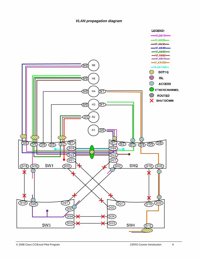
2. Catalyst Switch Configuration Section Configure the VLANs and the VLAN names according to the scenario specifications and assign the ports of the switches to these VLANs. Make sure the VLAN names are spelled correctly and match the letter case. Use the VLAN Table, Switch-to-Router Connections Table, and Switch-to-Switch Connections Table. Please see the following diagram for the VLAN layout:
© 2008 Cisco CCIExcel Pilot Program CIERS Course Introduction 9
VLAN propagation diagram

10 CIERS Graded Assessment Labs v1.0 © 2008 Cisco CCIEXcel Pilot Program
Issue: How do you enter a question mark in the domain name? Solution: Use control-V before you type “?”. Issue: Do not originate and process VTP updates, but allow VTP updates forwarding. Solution: Configure VTP mode Transparent. When set to VTP Transparent mode, switches forward VTP advertisements, but do not originate them or synchronize to them. Issue: The lab tells you to configure vlan 100 encapsulation on both logical interfaces of R1 and R6, however only vlans 10 and 40 are specified in the switch to router connections table. There is no vlan 100 in the vlan table as well. On SW3, configure an SVI interface on VLAN70. Disable CDP on the links between the ports 0/20 of SW1 and SW3, and between the ports 0/22 of SW2 and SW3. All three devices R1, R6 and SW3 must be communicating with each other on the same broadcast segment. Solution: The concept of dot1q “untagged” frames can be used to solve the issue with the tag 100. If the keyword “native” is specified on the logical interface of a router, the router will process the frames as untagged on that logical interface. If an untagged frame arrives on the ingress port of the catalyst switch configured with switchport trunk native vlan NNN, the frame will be processed by the instance of spanning tree associated with the vlan NNN, in our case VLAN10. Please see the diagram below. Note: In the command encapsulation dot1q 100 native on the routers, the number 100 can be any number, the number 100 is used to meet the requirement of this particular lab. The router will not do dot1q encapsulation, because the word “native” is specified. The router will send untagged Ethernet frames out the corresponding logical interface and will process received untagged Ethernet frames on this interface. This lab also requires you to configure different access VLAN numbers on the links between ports 0/20 and 0/22. Please see the diagram below. Since the switch ports are configured as access VLAN ports they send out untagged Ethernet frames as well, therefore there are no issues from the forwarding perspective between SW3, SW1 and SW2. CDP protocol will detect the mismatch in VLAN configuration and will report it via the logging mechanism. The requirement to disable CDP in this lab is there to stop these annoying console logging messages.

© 2008 Cisco CCIExcel Pilot Program CIERS Course Introduction 11
Note. SW3 is supposed to obtain its IP address from the DHCP pool configured on R1. Please read the DHCP section later in this answer key document. But at this step you could have assigned the IP address on the VLAN70 interface of SW3 manually to troubleshoot the issues related to this section. Configuration and Verification: R1:
interface FastEthernet0/0.100 encapsulation dot1Q 100 native ip address 131.10.160.1 255.255.255.0
R6:
interface FastEthernet0/0.100 encapsulation dot1Q 100 native ip address 131.10.160.6 255.255.255.0
SW1:
interface FastEthernet0/6 switchport trunk encapsulation dot1q switchport trunk native vlan 10

12 CIERS Graded Assessment Labs v1.0 © 2008 Cisco CCIEXcel Pilot Program
switchport trunk allowed vlan 10,40 switchport mode trunk interface FastEthernet0/20 switchport access vlan 10 switchport mode access no cdp enable end
SW2:
interface FastEthernet0/1 switchport trunk encapsulation dot1q switchport trunk native vlan 10 switchport trunk allowed vlan 10,40 switchport mode trunk end interface FastEthernet0/22 switchport access vlan 10 switchport mode access no cdp enable end
SW3:
interface FastEthernet0/20 switchport access vlan 70 switchport mode access no cdp enable end interface FastEthernet0/22 switchport access vlan 70 switchport mode access no cdp enable end
When you configure different VLANs on the link interfaces, you will see a logging message similar to the following:
4d18h: %CDP-4-NATIVE_VLAN_MISMATCH: Native VLAN mismatch discovered on FastEthernet0/20 (70), with SW1 FastEthernet0/20 (10).
The command no cdp enable stops these messages.
SW3#ping 131.10.160.255 Reply to request 0 from 131.10.160.1, 1 ms Reply to request 0 from 131.10.160.6, 1 ms Reply to request 1 from 131.10.160.1, 1 ms Reply to request 1 from 131.10.160.6, 1 ms Reply to request 2 from 131.10.160.1, 1 ms Reply to request 2 from 131.10.160.6, 1 ms Reply to request 3 from 131.10.160.1, 1 ms Reply to request 3 from 131.10.160.6, 1 ms Reply to request 4 from 131.10.160.1, 1 ms Reply to request 4 from 131.10.160.6, 1 ms SW3#
Issue: There will be no spanning tree instance for VLAN70 on SW3, however make sure that the traffic from SW3 is forwarded via SW3 access VLAN 70 port 0/22.
If SW3 port 0/22 fails, forwarding must continue via the port 0/20. Forwarding must be resumed via port 0/22 in 5 seconds after the port 0/22 is back up.
© 2008 Cisco CCIExcel Pilot Program CIERS Course Introduction 13
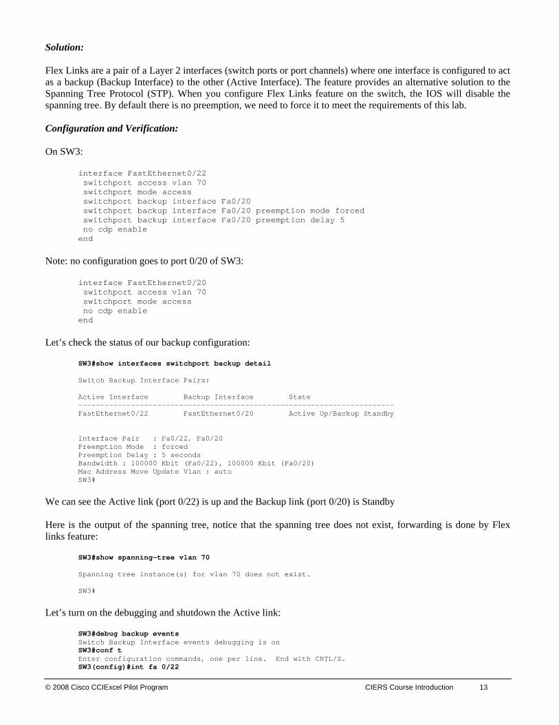
Solution: Flex Links are a pair of a Layer 2 interfaces (switch ports or port channels) where one interface is configured to act as a backup (Backup Interface) to the other (Active Interface). The feature provides an alternative solution to the Spanning Tree Protocol (STP). When you configure Flex Links feature on the switch, the IOS will disable the spanning tree. By default there is no preemption, we need to force it to meet the requirements of this lab. Configuration and Verification: On SW3:
interface FastEthernet0/22 switchport access vlan 70 switchport mode access switchport backup interface Fa0/20 switchport backup interface Fa0/20 preemption mode forced switchport backup interface Fa0/20 preemption delay 5 no cdp enable end
Note: no configuration goes to port 0/20 of SW3:
interface FastEthernet0/20 switchport access vlan 70 switchport mode access no cdp enable end
Let’s check the status of our backup configuration:
SW3#show interfaces switchport backup detail Switch Backup Interface Pairs: Active Interface Backup Interface State ------------------------------------------------------------------------ FastEthernet0/22 FastEthernet0/20 Active Up/Backup Standby Interface Pair : Fa0/22, Fa0/20 Preemption Mode : forced Preemption Delay : 5 seconds Bandwidth : 100000 Kbit (Fa0/22), 100000 Kbit (Fa0/20) Mac Address Move Update Vlan : auto SW3#
We can see the Active link (port 0/22) is up and the Backup link (port 0/20) is Standby Here is the output of the spanning tree, notice that the spanning tree does not exist, forwarding is done by Flex links feature:
SW3#show spanning-tree vlan 70 Spanning tree instance(s) for vlan 70 does not exist. SW3#
Let’s turn on the debugging and shutdown the Active link:
SW3#debug backup events Switch BackSW3#conf t
up Interface events debugging is on
Enter configuration commands, one per line. End with CNTL/Z. SW3(config)#int fa 0/22

14 CIERS Graded Assessment Labs v1.0 © 2008 Cisco CCIEXcel Pilot Program
SW3(config-if)#shut SW3(config-if)# 4d19h: sw_backup_int: Fa0/22 is now Down 4d19h: sw_backup_int: Fa0/20 is now Up SW3(config-if)# 4d19h: %LINK-5-CHANGED: Interface FastEthernet0/22, changed state to administratively down 4d19h: %LINEPROTO-5-UPDOWN: Line protocol on Interface FastEthernet0/22, changed state to down 4d19h: BACKUP_INT: intf Fa0/22, state down, bandwidth 100000 Kbps 4d19h: BACKUP_INT: setting WB 4d19h: BACKUP_INT: clearing WB 4d19h: BACKUP_INT: Pair Fa0/22 Fa0/20 mode forced, delay 5 seconds, Unscheduled SW3(config-if)#end
Check the status of the links:
SW3#show interfaces switchport backup detail Switch Backup Interface Pairs: Active Interface Backup Interface State ------------------------------------------------------------------------ FastEthernet0/22 FastEthernet0/20 Active Down/Backup Up Interface Pair : Fa0/22, Fa0/20 Preemption Mode : forced Preemption Delay : 5 seconds Bandwidth : 100000 Kbit (Fa0/22), 100000 Kbit (Fa0/20) Mac Address Move Update Vlan : auto
We can see the Active link (port 0/22) is Down and the Backup link (port 0/20) is Up. Let’s bring the port 0/22 back up and test the preemption:
SW3#conf t Enter configuration commSW3(config)#int fa 0/22
ands, one per line. End with CNTL/Z.
SW3(config-if)#no shut SW3(config-if)# 4d19h: sw_backup_int: Fa0/22 is now Waiting to sync 4d19h: sw_backup_int: Fa0/22 is now Waiting for peer state 4d19h: sw_backup_int: Fa0/22 is now Standby SW3(config-if)# 4d19h: %LINK-3-UPDOWN: Interface FastEthernet0/22, changed state to up 4d19h: %LINEPROTO-5-UPDOWN: Line protocol on Interface FastEthernet0/22, changed state to up 4d19h: BACKUP_INT: intf Fa0/22, state up, bandwidth 100000 Kbps 4d19h: BACKUP_INT: setting WB 4d19h: BACKUP_INT: clearing WB 4d19h: BACKUP_INT: AI Fa0/22 ai_state 2 ai_bw 100000, BI Fa0/20 bi_state 1 bi_bw 100000 4d19h: BACKUP_INT: Pair Fa0/22 Fa0/20 mode forced, delay 5 seconds, Scheduled SW3(config-if)# 4d19h: BACKUP_INT: AI Fa0/22 ai_state 2 ai_bw 100000, BI Fa0/20 bi_state 1 bi_bw 100000 4d19h: %BACKUP_INTERFACE-5-PREEMPT: Preempting interface Fa0/20 in backup pair (Fa0/22, Fa0/20), preemption mode is forced SW3(config-if)# 4d19h: sw_backup_int: Fa0/20 is now Down 4d19h: sw_backup_int: Fa0/22 is now Up 4d19h: sw_backup_int: Fa0/20 is now Waiting to sync 4d19h: sw_backup_int: Fa0/20 is now Waiting for peer state 4d19h: sw_backup_int: Fa0/20 is now Standby SW3(config-if)#end
Verify the link status again:
SW3#show interfaces switchport backup detail Switch Backup Interface Pairs: Active Interface Backup Interface State ------------------------------------------------------------------------ FastEthernet0/22 FastEthernet0/20 Active Up/Backup Standby

© 2008 Cisco CCIExcel Pilot Program CIERS Course Introduction 15
Interface Pair : Fa0/22, Fa0/20 Preemption Mode : forced Preemption Delay : 5 seconds Bandwidth : 100000 Kbit (Fa0/22), 100000 Kbit (Fa0/20) Mac Address Move Update Vlan : auto SW3#
Issue: Only SW2 switch should be able to start the automatic PAGP aggregation process. Solution: The interface starts actively sending PAGP negotiation protocol packets if it is configured with the keyword “desirable”. The “desirable” mode should be applied on SW2. If the interface is configured as “auto”, it listens to the PAGP packets and responds to them, but it does not initiate PAGP negotiation itself. The “auto” mode should be applied on the SW1. Verification:
SW2#show pagp internal Flags: S - Device is sending Slow hello. C - Device is in Consistent state. A - Device is in Auto mode. d - PAgP is down Timers: H - Hello timer is running. Q - Quit timer is running. S - Switching timer is running. I - Interface timer is running. Channel group 1 Hello Partner PAgP Learning Group Port Flags State Timers Interval Count Priority Method Ifindex Fa0/23 SC U6/S7 H 30s 1 128 Any 29 Fa0/24 SC U6/S7 H 30s 1 128 Any 29 SW2# SW2#show pagp neighbor Flags: S - Device is sending Slow hello. C - Device is in Consistent state. A - Device is in Auto mode. P - Device learns on physical port. Channel group 1 neighbors Partner Partner Partner Partner Group Port Name Device ID Port Age Flags Cap. Fa0/23 SW1 0009.e898.9800 Fa0/23 5s SAC 10001 Fa0/24 SW1 0009.e898.9800 Fa0/23 17s SAC 10001 SW2#
Issue: Allow only necessary VLANs on the link between SW1 and SW2. Solution: If you create a Layer 2 diagram like the one above, it is easy to determine which VLANs must cross each trunk link. Use the command switchport trunk allowed vlan 10,20,30,40,1026 on the port-channel interface. Issue: How do you authorize the port for traffic based on authentication of the client with the RADIUS server? Solution: 802.1X Port-Based Authentication will solve this task. The following steps can be configured on the catalyst SW2:
aaa new-model

16 CIERS Graded Assessment Labs v1.0 © 2008 Cisco CCIEXcel Pilot Program
aaa authentication dot1x default group radius radius-server host 131.10.160.200 (see note below) dot1x system-auth-control ! interface FastEthernet0/17 switchport access vlan 30 switchport mode access dot1x port-control auto
The IOS will generate the following command for the default Radius ports: radius-server host 131.10.160.200 auth-port 1812 acct-port 1813 For additional information check: http://www.cisco.com/univercd/cc/td/doc/product/lan/c3550/12119ea1/3550scg/sw8021x.htm#1002608
Note To obtain a comprehensive view of the configuration tasks in this section, access the SHOWiT engine. With the SHOWiT engine, you can enter in over 1000 IOS commands as well a collection of NMC proprietary commands such as “show all”.
3. IPv4 OSPF Section
Caution All OSPF routers must be configured with only one OSPF Process ID (PID). Use your IGP diagram to help guide configuration
Issue: OSPF adjacency between R1 and R2, R2 and R3, R2 and R5 must be formed statically without DR/BDR election. Solution: The keywords are “statically” and “without DR/BDR election”. The “statically” suggests unicast addressing for HELLO packets and database exchange. “Without DR/BDR election” matches either “point-to-point” or “point-to-multipoint” OSPF network types. The “point-to-point” OSPF network type cannot be modified to use unicast addressing, therefore the only option left is ip ospf network point-to-multipoint nonbroadcast. This command should be applied on all interfaces involved in the specified OSPF adjacencies. Do not forget to configure neighbors under the OSPF process to trigger the HELLO exchange. Here is an example of the configuration to fulfill the requirement; R2 and R5 were used to generate the example output: R2:
interface Serial0/0.21 point-to-point ip address 131.10.21.2 255.255.255.0 ip ospf network point-to-multipoint non-broadcast frame-relay interface-dlci 201 ! interface Serial0/0.23 point-to-point ip address 131.10.23.2 255.255.255.0 ip ospf network point-to-multipoint non-broadcast frame-relay interface-dlci 203 ! interface FastEthernet0/0.50 encapsulation dot1Q 50
© 2008 Cisco CCIExcel Pilot Program CIERS Course Introduction 17
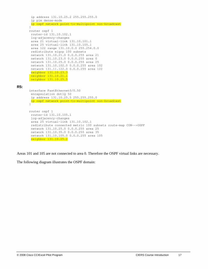
ip address 131.10.25.2 255.255.255.0 ip pim dense-mode ip ospf network point-to-multipoint non-broadcast ! router ospf 1 router-id 131.10.102.1 log-adjacency-changes area 21 virtual-link 131.10.101.1 area 25 virtual-link 131.10.105.1 area 122 range 131.10.0.0 255.254.0.0 redistribute eigrp 100 subnets network 131.10.21.0 0.0.0.255 area 21 network 131.10.23.0 0.0.0.255 area 0 network 131.10.25.0 0.0.0.255 area 25 network 131.10.102.0 0.0.0.255 area 102 network 131.11.122.0 0.0.0.255 area 122 neighbor 131.10.23.3 neighbor 131.10.21.1 neighbor 131.10.25.5
R5:
interface FastEthernet0/0.50 encapsulation dot1Q 50 ip address 131.10.25.5 255.255.255.0 ip ospf network point-to-multipoint non-broadcast ! router ospf 1 router-id 131.10.105.1 log-adjacency-changes area 25 virtual-link 131.10.102.1 redistribute connected metric 100 subnets route-map CON-->OSPF network 131.10.25.0 0.0.0.255 area 25 network 131.10.35.0 0.0.0.255 area 35 network 131.10.105.0 0.0.0.255 area 105 neighbor 131.10.25.2
Areas 101 and 105 are not connected to area 0. Therefore the OSPF virtual links are necessary. The following diagram illustrates the OSPF domain:
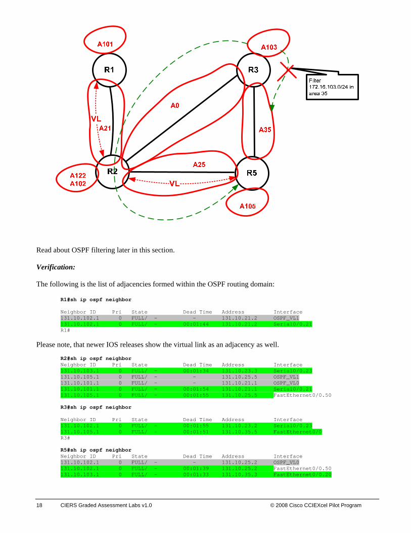
Read about OSPF filtering later in this section. Verification: The following is the list of adjacencies formed within the OSPF routing domain:
R1#sh ip ospf neighbor Neighbor ID Pri State Dead Time Address Interface 131.10.102.1 0 FULL/ - - 131.10.21.2 OSPF_VL1 131.10.102.1 0 FULL/ - 00:01:44 131.10.21.2 Serial0/0.21 R1#
Please note, that newer IOS releases show the virtual link as an adjacency as well.
R2#sh ip ospf neighbor Neighbor ID Pri State Dead Time Address Interface 131.10.103.1 0 FULL/ - 00:01:34 131.10.23.3 Serial0/0.23 131.10.105.1 0 FULL/ - - 131.10.25.5 OSPF_VL1 131.10.101.1 0 FULL/ - - 131.10.21.1 OSPF_VL0 131.10.101.1 0 FULL/ - 00:01:54 131.10.21.1 Serial0/0.21 1 31.10.105.1 0 FULL/ - 00:01:55 131.10.25.5 FastEthernet0/0.50
R3#sh ip ospf neighbor Neighbor ID Pri State Dead Time Address Interface 131.10.102.1 0 FULL/ - 00:01:55 131.10.23.2 Serial0/0.23 131.10.105.1 0 FULL/ - 00:01:51 131.10.35.5 FastEthernet0/0 R3# R5#sh ip ospf neighbor Neighbor ID Pri State Dead Time Address Interface 131.10.102.1 0 FULL/ - - 131.10.25.2 OSPF_VL0 131.10.102.1 0 FULL/ - 00:01:39 131.10.25.2 FastEthernet0/0.50 131.10.103.1 0 FULL/ - 00:01:33 131.10.35.3 FastEthernet0/0.20
18 CIERS Graded Assessment Labs v1.0 © 2008 Cisco CCIEXcel Pilot Program
© 2008 Cisco CCIExcel Pilot Program CIERS Course Introduction 19
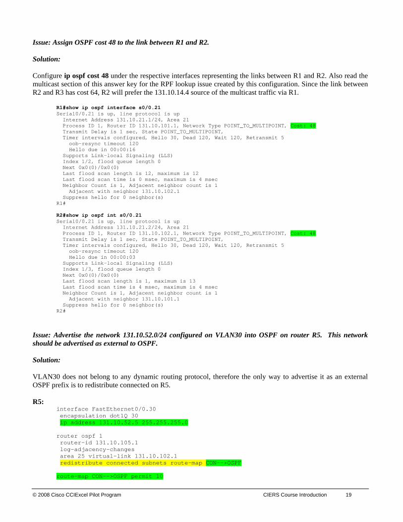
Issue: Assign OSPF cost 48 to the link between R1 and R2. Solution: Configure ip ospf cost 48 under the respective interfaces representing the links between R1 and R2. Also read the multicast section of this answer key for the RPF lookup issue created by this configuration. Since the link between R2 and R3 has cost 64, R2 will prefer the 131.10.14.4 source of the multicast traffic via R1.
R1#show ip ospf interface s0/0.21 Serial0/0.21 is up, line protocol is up Internet Address 131.10.21.1/24, Area 21 Process ID 1, Router ID 131.10.101.1, Network Type POINT_TO_MULTIPOINT, Cost: 48 Transmit Delay is 1 sec, State POINT_TO_MULTIPOINT, Timer intervals configured, Hello 30, Dead 120, Wait 120, Retransmit 5 oob-resync timeout 120 Hello due in 00:00:16 Supports Link-local Signaling (LLS) Index 1/2, flood queue length 0 Next 0x0(0)/0x0(0) Last flood scan length is 12, maximum is 12 Last flood scan time is 0 msec, maximum is 4 msec Neighbor Count is 1, Adjacent neighbor count is 1 Adjacent with neighbor 131.10.102.1 Suppress hello for 0 neighbor(s) R1# R2#show ip ospf int s0/0.21 Serial0/0.21 is up, line protocol is up Internet Address 131.10.21.2/24, Area 21 Process ID 1, Router ID 131.10.102.1, Network Type POINT_TO_MULTIPOINT, Cost: 48 Transmit Delay is 1 sec, State POINT_TO_MULTIPOINT, Timer intervals configured, Hello 30, Dead 120, Wait 120, Retransmit 5 oob-resync timeout 120 Hello due in 00:00:03 Supports Link-local Signaling (LLS) Index 1/3, flood queue length 0 Next 0x0(0)/0x0(0) Last flood scan length is 1, maximum is 13 Last flood scan time is 4 msec, maximum is 4 msec Neighbor Count is 1, Adjacent neighbor count is 1 Adjacent with neighbor 131.10.101.1 Suppress hello for 0 neighbor(s) R2#
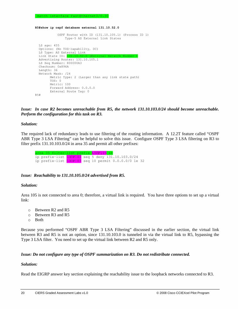
Issue: Advertise the network 131.10.52.0/24 configured on VLAN30 into OSPF on router R5. This network should be advertised as external to OSPF. Solution: VLAN30 does not belong to any dynamic routing protocol, therefore the only way to advertise it as an external OSPF prefix is to redistribute connected on R5. R5:
interface FastEthernet0/0.30 encapsulation dot1Q 30 ip address 131.10.52.5 255.255.255.0 router ospf 1 router-id 131.10.105.1 log-adjacency-changes area 25 virtual-link 131.10.102.1 redistribute connected subnets route-map CON-->OSPF route-map CON-->OSPF permit 10
20 CIERS Graded Assessment Labs v1.0 © 2008 Cisco CCIEXcel Pilot Program
match interface FastEthernet0/0.30
R5#show ip ospf database external 131.10.52.0 OSPF Router with ID (131.10.105.1) (Process ID 1) Type-5 AS External Link States LS age: 455 Options: (No TOS-capability, DC) LS Type: AS External Link Link State ID: 131.10.52.0 (External Network Number ) Advertising Router: 131.10.105.1 LS Seq Number: 800000A3 Checksum: 0x896A Length: 36 Network Mask: /24 Metric Type: 2 (Larger than any link state path) TOS: 0 Metric: 100 Forward Address: 0.0.0.0 External Route Tag: 0 R5#
Issue: In case R2 becomes unreachable from R5, the network 131.10.103.0/24 should become unreachable. Perform the configuration for this task on R3. Solution: The required lack of redundancy leads to use filtering of the routing information. A 12.2T feature called “OSPF ABR Type 3 LSA Filtering” can be helpful to solve this issue. Configure OSPF Type 3 LSA filtering on R3 to filter prefix 131.10.103.0/24 in area 35 and permit all other prefixes:
area 35 filter-list prefix LOOP103 in ip prefix-list LOOP103 seq 5 deny 131.10.103.0/24 ip prefix-list LOOP103 seq 10 permit 0.0.0.0/0 le 32
Issue: Reachability to 131.10.105.0/24 advertised from R5. Solution: Area 105 is not connected to area 0; therefore, a virtual link is required. You have three options to set up a virtual link:
o Between R2 and R5 o Between R3 and R5 o Both
Because you performed “OSPF ABR Type 3 LSA Filtering” discussed in the earlier section, the virtual link between R3 and R5 is not an option, since 131.10.103.0 is tunneled in via the virtual link to R5, bypassing the Type 3 LSA filter. You need to set up the virtual link between R2 and R5 only. Issue: Do not configure any type of OSPF summarization on R3. Do not redistribute connected. Solution: Read the EIGRP answer key section explaining the reachability issue to the loopback networks connected to R3.

© 2008 Cisco CCIExcel Pilot Program CIERS Course Introduction 21
Note To obtain a comprehensive view of the configuration tasks in this section, access the SHOWiT engine. With the SHOWiT engine, you can enter in over 1000 IOS commands as well a collection of NMC proprietary commands such as “show all”.
4. IPv4 EIGRP Section Issue: Configure EIGRP AS 100 between routers R2 and SW1 and EIGRP AS 200 between routers SW1 and SW2. Solution: Router SW1 will be running two processes: one for AS100 and the other for AS200. Issue: Advertise only a summary best describing networks 131.10.0.0/16 and 131.11.0.0/16 from R2 to SW1 and SW2. Solution: Unlike RIP, EIGRP allows advertisement of supernets with the interface command “ip summary” Here are the logical steps to fulfill this requirement: 1. Inject a prefix in the EIGRP 100 topology via redistribution. You can redistribute connected or redistribute OSPF. This step is necessary for the ip summary command to work. “Redistribute OSPF” is used in the final configuration. 2. On the interface connected to AS 200 on R2 configure:
ip summary-address eigrp 100 131.10.0.0 255.254.0.0 3. Redistribute EGRP AS100 routing information into EIGRP 200 on SW1, to make sure that the summary will be propagated to SW2 as well. The resulting routing tables should look similar to the following:
SW1#sh ip route Codes: C - connected, S - static, I - IGRP, R - RIP, M - mobile, B - BGP D - EIGRP, EX - EIGRP external, O - OSPF, IA - OSPF inter area N1 - OSPF NSSA external type 1, N2 - OSPF NSSA external type 2 E1 - OSPF external type 1, E2 - OSPF external type 2, E - EGP i - IS-IS, L1 - IS-IS level-1, L2 - IS-IS level-2, ia - IS-IS inter area * - candidate default, U - per-user static route, o - ODR P - periodic downloaded static route Gateway of last resort is not set 131.10.0.0/24 is subnetted, 1 subnets C 131.10.122.0 is directly connected, Vlan30 D EX 131.10.0.0/15 [170/2585856] via 131.10.122.2, 00:14:57, Vlan30 SW2# show ip route Codes: C - connected, S - static, I - IGRP, R - RIP, M - mobile, B - BGP D - EIGRP, EX - EIGRP external, O - OSPF, IA - OSPF inter area N1 - OSPF NSSA external type 1, N2 - OSPF NSSA external type 2 E1 - OSPF external type 1, E2 - OSPF external type 2, E - EGP i - IS-IS, L1 - IS-IS level-1, L2 - IS-IS level-2, ia - IS-IS inter area * - candidate default, U - per-user static route, o - ODR P - periodic downloaded static route

22 CIERS Graded Assessment Labs v1.0 © 2008 Cisco CCIEXcel Pilot Program
Gateway of last resort is not set 131.10.0.0/24 is subnetted, 3 subnets C 131.10.52.0 is directly connected, Vlan30 C 131.10.100.0 is directly connected, Vlan1026 D EX 131.10.122.0 [90/28416] via 131.10.100.10, 04:48:45, Vlan1026 D EX 131.10.0.0/15 [170/2585856] via 131.10.100.10, 04:48:35, Vlan1026
Issue: Configure MD5 authentication on EIGRP speakers. Solution: 1. Configure the same key chain on both routers. Names are up to you:
key chain keyeigrp200 key 1 key-string eigrp200
2. On all interfaces involved in the EIGRP AS200 routing updates exchange configure the following:
interface Vlan30 ip authentication mode eigrp 200 md5 ip authentication key-chain eigrp 200 keyeigrp200 SW1#show ip eigrp interfaces detail vlan 1026 IP-EIGRP interfaces for process 200 Xmit Queue Mean Pacing Time Multicast Pending Interface Peers Un/Reliable SRTT Un/Reliable Flow Timer Routes Vl1026 1 0/0 0 0/10 3812 0 Next xmit serial <none> Un/reliable mcasts: 0/2 Un/reliable ucasts: 4/3 Mcast exceptions: 0 CR packets: 0 ACKs suppressed: 0 Retransmissions sent: 1 Out-of-sequence rcvd: 0 Authentication mode is md5, key-chain is "keyeigrp200" IP-EIGRP interfaces for process 100 Xmit Queue Mean Pacing Time Multicast Pending Interface Peers Un/Reliable SRTT Un/Reliable Flow Timer Routes SW1#show key chain Key-chain keyeigrp200: key 1 -- text "eigrp200" accept lifetime (always valid) - (always valid) [valid now] send lifetime (always valid) - (always valid) [valid now] SW1#
Issue: Configure EIGRP AS 300 Between R1, R4 and R3, summarize loopback networks from R4 using the optimal summary. Do not advertise more specific prefixes from the summary range. Solution: The loopback networks should be advertised in EIGRP AS300 according to the IGP diagram. Summarize the loopback networks on the Virtual Template interface:
interface Virtual-Template1 ip address 131.10.14.4 255.255.255.0 ip summary-address eigrp 300 131.10.224.0 255.255.252.0 5

© 2008 Cisco CCIExcel Pilot Program CIERS Course Introduction 23
Since the summarized networks are internal to EIGRP AS 300, the summary will suppress more specific networks from its range:
R1#show ip route eigrp | inc 131.10.22 D 131.10.224.0/22 [90/2713600] via 131.10.14.4, 2d02h, Virtual-Access1 R1#
Issue: Advertise only loopback 236, 237 and 238 networks from R3 as EIGRP external networks. Summarize loopback 236, 237 and 238 networks from R3 using the optimal summary, do not advertise more specific prefixes from R3. Solution: There are orphaned loopback networks Lo233, Lo234, Lo235 on R3 which are not advertised in any dynamic protocols (redistribute connected is not permitted under OSPF configuration on R3 , see the OSPF requirements) and are not redistributed as connected since the requirement specifically lists the loopback 236, 237 and 238 only to be redistributed as connected. You still need to provide connectivity to all networks on R3. The OSPF section explicitly prohibits any OSPF summarization on R3, therefore the only remaining option is to summarize via EIGRP AS 300. This summary should be broad enough to allow connectivity to loopback networks Lo236, Lo 237, Lo 238 and Lo233, Lo234, Lo235 and be optimal at the same time:
interface Serial0/0.13 point-to-point ip address 131.10.13.3 255.255.255.0 ip summary-address eigrp 300 131.10.232.0 255.255.248.0 5 router eigrp 300 redistribute connected route-map CONN2EIGRP redistribute ospf 1 network 131.10.13.0 0.0.0.255 default-metric 1500 100 255 3 1500 auto-summary route-map CONN2EIGRP permit 10 match interface Loopback236 Loopback237 Loopback238 R1#show ip route eigrp | inc 131.10.23 D 131.10.232.0/21 [90/2297856] via 131.10.13.3, 2d02h, Serial0/0.13 R1#
Note To obtain a comprehensive view of the configuration tasks in this section, access the SHOWiT engine. With the SHOWiT engine, you can enter in over 1000 IOS commands as well a collection of NMC proprietary commands such as “show all”.
5. IPv4 RIP Issue: This scenario explicitly asks you to configure version 2. Solution: Configuring version 2 under the RIP process on routers R1 and R6 can do this. Verification:
24 CIERS Graded Assessment Labs v1.0 © 2008 Cisco CCIEXcel Pilot Program
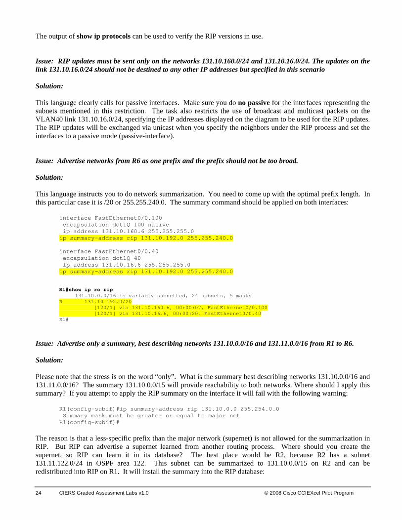
The output of show ip protocols can be used to verify the RIP versions in use. Issue: RIP updates must be sent only on the networks 131.10.160.0/24 and 131.10.16.0/24. The updates on the link 131.10.16.0/24 should not be destined to any other IP addresses but specified in this scenario Solution: This language clearly calls for passive interfaces. Make sure you do no passive for the interfaces representing the subnets mentioned in this restriction. The task also restricts the use of broadcast and multicast packets on the VLAN40 link 131.10.16.0/24, specifying the IP addresses displayed on the diagram to be used for the RIP updates. The RIP updates will be exchanged via unicast when you specify the neighbors under the RIP process and set the interfaces to a passive mode (passive-interface). Issue: Advertise networks from R6 as one prefix and the prefix should not be too broad. Solution: This language instructs you to do network summarization. You need to come up with the optimal prefix length. In this particular case it is /20 or 255.255.240.0. The summary command should be applied on both interfaces:
interface FastEthernet0/0.100 encapsulation dot1Q 100 native ip address 131.10.160.6 255.255.255.0 ip summary-address rip 131.10.192.0 255.255.240.0 interface FastEthernet0/0.40 encapsulation dot1Q 40 ip address 131.10.16.6 255.255.255.0 ip summary-address rip 131.10.192.0 255.255.240.0 R1#show ip ro rip 131.10.0.0/16 is variably subnetted, 24 subnets, 5 masks R 131.10.192.0/20 [120/1] via 131.10.160.6, 00:00:07, FastEthernet0/0.100 [120/1] via 131.10.16.6, 00:00:20, FastEthernet0/0.40 R1#
Issue: Advertise only a summary, best describing networks 131.10.0.0/16 and 131.11.0.0/16 from R1 to R6. Solution: Please note that the stress is on the word “only”. What is the summary best describing networks 131.10.0.0/16 and 131.11.0.0/16? The summary 131.10.0.0/15 will provide reachability to both networks. Where should I apply this summary? If you attempt to apply the RIP summary on the interface it will fail with the following warning:
R1(config-subif)#ip summary-address rip 131.10.0.0 255.254.0.0 Summary mask must be greater or equal to major net R1(config-subif)#
The reason is that a less-specific prefix than the major network (supernet) is not allowed for the summarization in RIP. But RIP can advertise a supernet learned from another routing process. Where should you create the supernet, so RIP can learn it in its database? The best place would be R2, because R2 has a subnet 131.11.122.0/24 in OSPF area 122. This subnet can be summarized to 131.10.0.0/15 on R2 and can be redistributed into RIP on R1. It will install the summary into the RIP database:
© 2008 Cisco CCIExcel Pilot Program CIERS Course Introduction 25
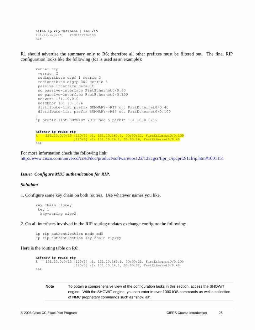
R1#sh ip rip database | inc /15 131.10.0.0/15 redistributed R1#
R1 should advertise the summary only to R6; therefore all other prefixes must be filtered out. The final RIP configuration looks like the following (R1 is used as an example):
router rip version 2 redistribute ospf 1 metric 3 redistribute eigrp 300 metric 3 passive-interface default no passive-interface FastEthernet0/0.40 no passive-interface FastEthernet0/0.100 network 131.10.0.0 neighbor 131.10.16.6 distribute-list prefix SUMMARY->RIP out FastEthernet0/0.40 distribute-list prefix SUMMARY->RIP out FastEthernet0/0.100 ! ip prefix-list SUMMARY->RIP seq 5 permit 131.10.0.0/15 R6#show ip route rip R 131.10.0.0/15 [120/3] via 131.10.160.1, 00:00:22, FastEthernet0/0.100 [120/3] via 131.10.16.1, 00:00:26, FastEthernet0/0.40 R6#
For more information check the following link: http://www.cisco.com/univercd/cc/td/doc/product/software/ios122/122cgcr/fipr_c/ipcprt2/1cfrip.htm#1001151 Issue: Configure MD5 authentication for RIP. Solution: 1. Configure same key chain on both routers. Use whatever names you like.
key chain ripkey key 1 key-string ripv2
2. On all interfaces involved in the RIP routing updates exchange configure the following:
ip rip authentication mode md5 ip rip authentication key-chain ripkey
Here is the routing table on R6:
R6#show ip route rip R 131.10.0.0/15 [120/3] via 131.10.160.1, 00:00:21, FastEthernet0/0.100 [120/3] via 131.10.16.1, 00:00:02, FastEthernet0/0.40 R6#
Note To obtain a comprehensive view of the configuration tasks in this section, access the SHOWiT engine. With the SHOWiT engine, you can enter in over 1000 IOS commands as well a collection of NMC proprietary commands such as “show all”.

26 CIERS Graded Assessment Labs v1.0 © 2008 Cisco CCIEXcel Pilot Program
6. IPv4 Redistribution Section IPv4 Reachability Verification: One way to test that your redistribution satisfies the goal of universal connectivity is to run a TCL script like the one below on each router. TCL scripting support is available in the IOS versions used here on routers R1, R2, R3, R4, R5 and R6 (the 3600 and 2600 models). The simple script below lists all of the IP addresses in our pod. It can be built once in notepad, and then pasted into each router to automate pings. There is a paper on TCL scripting available in the READiT section of the Netmasterclass website. Some addresses are used in later tasks and may not be reachable at this point. Run tclsh in privileged mode, paste the script below, and then issue the command tclq.
foreach address { 131.10.13.1 131.10.21.1 131.10.16.1 131.10.14.1 131.10.101.1 131.10.160.1 131.10.21.2 131.10.23.2 131.10.25.2 131.10.102.1 131.11.122.1 131.10.122.2 131.10.35.3 131.10.13.3 131.10.23.3 131.10.103.1 131.10.113.1 131.10.233.1 131.10.234.1 131.10.235.1 131.10.236.1 131.10.237.1 131.10.238.1 131.10.14.4 131.10.224.1 131.10.225.1 131.10.227.1 131.10.35.5 131.10.52.5 131.10.25.5 131.10.105.1 131.10.160.6 131.10.16.6 131.10.196.1 131.10.200.1 131.10.204.1 131.10.160.7 131.10.100.10 131.10.122.10 131.10.52.20 131.10.100.20} {ping $address}
We also need to make sure that our solution is a stable one. If we have split-horizon or other route feedback problems routes may continually be inserted and removed from our routing tables. We can test stability by observing the output of debug IP routing. Finally, we need to make sure that our routes are optimal: that native prefixes are routed by native protocols and that we are using the shortest paths. This requires close examination of each routing table.

© 2008 Cisco CCIExcel Pilot Program CIERS Course Introduction 27
Note To obtain a comprehensive view of the configuration tasks in this section, access the SHOWiT engine. With the SHOWiT engine, you can enter in over 1000 IOS commands as well a collection of NMC proprietary commands such as “show all”.
7. Border Gateway Protocol Section Issue: Configure R2, R3 and R5 in the same AS without using route reflectors or introducing any new AS numbers. Solution: In other words R2, R3 and R5 should be peered without route reflectors and confederations. That leaves one option – a full mesh of IBGP peer relationships. Issue: Configure peer relationship between AS 2010 and 1080 using routers R1, R2 and R3. Solution: Since the AS numbers are different, configure EBGP peer relationships between R1-R2 and R1-R3. Issue: Configure a BGP peer relationship between R4 and the backbone router BB1 that is in AS 9999. Solution: The backbone router is preconfigured and waiting for the right neighbor statement on your side. Make sure you apply the correct “NX” IP address on the interface of R4 connected to backbone and the correct AS number. Also, you have to make sure that VLAN 150 is configured and propagated properly on the switches. Verify basic connectivity between router R4 and BB1 router using ping. Issue: Allow only the given networks from the backbone AS 9999. Use a prefix list with the minimal number of statements to accomplish this task. Solution: First, make sure you receive the prefixes from the backbone router, and then apply your filtering solution. In this task you are required to apply a prefix list with the minimal statements. Let’s look at what is received from the backbone before the filter is applied:
R4#sh ip bgp BGP table version is 14, local router ID is 131.10.227.1 Status codes: s suppressed, d damped, h history, * valid, > best, i - internal Origin codes: i - IGP, e - EGP, ? - incomplete Network Next Hop Metric LocPrf Weight Path *> 166.103.140.0/24 150.100.10.110 0 0 9999 i *> 166.103.141.0/24 150.100.10.110 0 0 9999 i *> 166.103.142.0/24 150.100.10.110 0 0 9999 i *> 166.103.143.0/24 150.100.10.110 0 0 9999 i *> 170.10.133.0/24 150.100.10.110 0 0 9999 i *> 170.10.134.0/24 150.100.10.110 0 0 9999 i *> 170.10.135.0/24 150.100.10.110 0 0 9999 i R4#
28 CIERS Graded Assessment Labs v1.0 © 2008 Cisco CCIEXcel Pilot Program
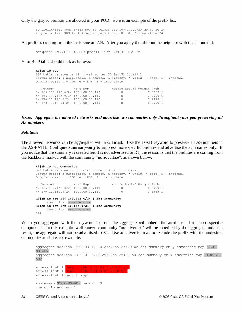
Only the grayed prefixes are allowed in your POD. Here is an example of the prefix list:
ip prefix-list SUM142-134 seq 10 permit 166.103.142.0/23 ge 24 le 24 ip prefix-list SUM142-134 seq 20 permit 170.10.134.0/23 ge 24 le 24
All prefixes coming from the backbone are /24. After you apply the filter on the neighbor with this command:
neighbor 150.100.10.110 prefix-list SUM142-134 in Your BGP table should look as follows:
R4#sh ip bgp BGP table version is 11, local router ID is 131.10.227.1 Status codes: s suppressed, d damped, h history, * valid, > best, i - internal Origin codes: i - IGP, e - EGP, ? - incomplete Network Next Hop Metric LocPrf Weight Path *> 166.103.142.0/24 150.100.10.110 0 0 9999 i *> 166.103.143.0/24 150.100.10.110 0 0 9999 i *> 170.10.134.0/24 150.100.10.110 0 0 9999 i *> 170.10.135.0/24 150.100.10.110 0 0 9999 i
Issue: Aggregate the allowed networks and advertise two summaries only throughout your pod preserving all AS numbers. Solution: The allowed networks can be aggregated with a /23 mask. Use the as-set keyword to preserve all AS numbers in the AS-PATH. Configure summary-only to suppress more specific prefixes and advertise the summaries only. If you notice that the summary is created but it is not advertised to R1, the reason is that the prefixes are coming from the backbone marked with the community “no advertise”, as shown below.
R4#sh ip bgp community BGP table version is 8, local router ID is 131.10.227.1 Status codes: s suppressed, d damped, h history, * valid, > best, i - internal Origin codes: i - IGP, e - EGP, ? - incomplete Network Next Hop Metric LocPrf Weight Path *> 166.103.143.0/24 150.100.10.110 0 0 9999 i *> 170.10.135.0/24 150.100.10.110 0 0 9999 i R4#sh ip bgp 166.103.143.0/24 | inc Community Community: no-advertise R4#sh ip bgp 170.10.135.0/24 | inc Community Community: no-advertise R4#
When you aggregate with the keyword “as-set”, the aggregate will inherit the attributes of its more specific components. In this case, the well-known community “no-advertise” will be inherited by the aggregate and; as a result, the aggregate will not be advertised to R1. Use an advertise-map to exclude the prefix with the undesired community attribute, for example:
aggregate-address 166.103.142.0 255.255.254.0 as-set summary-only advertise-map STOP-NO-ADV aggregate-address 170.10.134.0 255.255.254.0 as-set summary-only advertise-map STOP-NO-ADV access-list 1 deny 166.103.143.0 0.0.0.255 access-list 1 deny 170.10.135.0 0.0.0.255 access-list 1 permit any ! route-map STOP-NO-ADV permit 10 match ip address 1
© 2008 Cisco CCIExcel Pilot Program CIERS Course Introduction 29
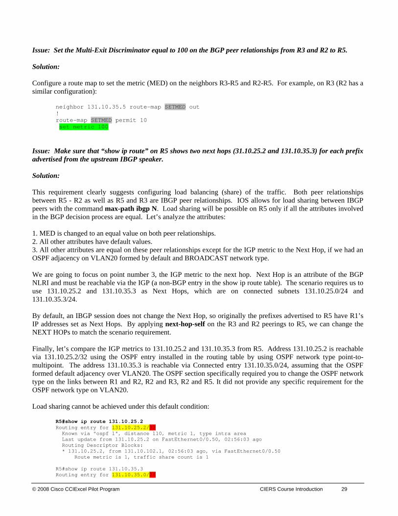
Issue: Set the Multi-Exit Discriminator equal to 100 on the BGP peer relationships from R3 and R2 to R5. Solution: Configure a route map to set the metric (MED) on the neighbors R3-R5 and R2-R5. For example, on R3 (R2 has a similar configuration):
neighbor 131.10.35.5 route-map SETMED out ! route-map SETMED permit 10 set metric 100
Issue: Make sure that “show ip route” on R5 shows two next hops (31.10.25.2 and 131.10.35.3) for each prefix advertised from the upstream IBGP speaker. Solution: This requirement clearly suggests configuring load balancing (share) of the traffic. Both peer relationships between R5 - R2 as well as R5 and R3 are IBGP peer relationships. IOS allows for load sharing between IBGP peers with the command max-path ibgp N. Load sharing will be possible on R5 only if all the attributes involved in the BGP decision process are equal. Let’s analyze the attributes: 1. MED is changed to an equal value on both peer relationships. 2. All other attributes have default values. 3. All other attributes are equal on these peer relationships except for the IGP metric to the Next Hop, if we had an OSPF adjacency on VLAN20 formed by default and BROADCAST network type. We are going to focus on point number 3, the IGP metric to the next hop. Next Hop is an attribute of the BGP NLRI and must be reachable via the IGP (a non-BGP entry in the show ip route table). The scenario requires us to use 131.10.25.2 and 131.10.35.3 as Next Hops, which are on connected subnets 131.10.25.0/24 and 131.10.35.3/24. By default, an IBGP session does not change the Next Hop, so originally the prefixes advertised to R5 have R1’s IP addresses set as Next Hops. By applying next-hop-self on the R3 and R2 peerings to R5, we can change the NEXT HOPs to match the scenario requirement. Finally, let’s compare the IGP metrics to 131.10.25.2 and 131.10.35.3 from R5. Address 131.10.25.2 is reachable via 131.10.25.2/32 using the OSPF entry installed in the routing table by using OSPF network type point-to-multipoint. The address 131.10.35.3 is reachable via Connected entry 131.10.35.0/24, assuming that the OSPF formed default adjacency over VLAN20. The OSPF section specifically required you to change the OSPF network type on the links between R1 and R2, R2 and R3, R2 and R5. It did not provide any specific requirement for the OSPF network type on VLAN20. Load sharing cannot be achieved under this default condition:
R5#show ip route 131.10.25.2 Routing entry for 131.10.25.2/32 Known via "ospf 1", distance 110, metric 1, type intra area Last update from 131.10.25.2 on FastEthernet0/0.50, 02:56:03 ago Routing Descriptor Blocks: * 131.10.25.2, from 131.10.102.1, 02:56:03 ago, via FastEthernet0/0.50 Route metric is 1, traffic share count is 1 R5#show ip route 131.10.35.3 Routing entry for 131.10.35.0/24
30 CIERS Graded Assessment Labs v1.0 © 2008 Cisco CCIEXcel Pilot Program
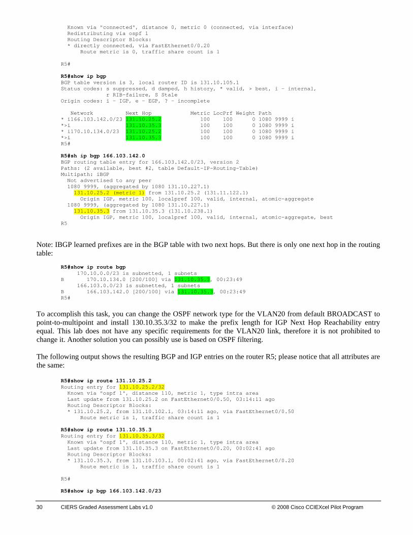
Known via "connected", distance 0, metric 0 (connected, via interface) Redistributing via ospf 1 Routing Descriptor Blocks: * directly connected, via FastEthernet0/0.20 Route metric is 0, traffic share count is 1 R5# R5#show ip bgp BGP table version is 3, local router ID is 131.10.105.1 Status codes: s suppressed, d damped, h history, * valid, > best, i - internal, r RIB-failure, S Stale Origin codes: i - IGP, e - EGP, ? - incomplete Network Next Hop Metric LocPrf Weight Path * i166.103.142.0/23 131.10.25.2 100 100 0 1080 9999 i *>i 131.10.35.3 100 100 0 1080 9999 i * i170.10.134.0/23 131.10.25.2 100 100 0 1080 9999 i *>i 131.10.35.3 100 100 0 1080 9999 i R5# R5#sh ip bgp 166.103.142.0 BGP routing table entry for 166.103.142.0/23, version 2 Paths: (2 available, best #2, table Default-IP-Routing-Table) Multipath: iBGP Not advertised to any peer 1080 9999, (aggregated by 1080 131.10.227.1) 131.10.25.2 (metric 1) from 131.10.25.2 (131.11.122.1) Origin IGP, metric 100, localpref 100, valid, internal, atomic-aggregate 1080 9999, (aggregated by 1080 131.10.227.1) 131.10.35.3 from 131.10.35.3 (131.10.238.1) Origin IGP, metric 100, localpref 100, valid, internal, atomic-aggregate, best R5
Note: IBGP learned prefixes are in the BGP table with two next hops. But there is only one next hop in the routing table:
R5#show ip route bgp 170.10.0.0/23 is subnetted, 1 subnets B 170.10.134.0 [200/100] via 131.10.35.3, 00:23:49 166.103.0.0/23 is subnetted, 1 subnets B 166.103.142.0 [200/100] via 131.10.35.3, 00:23:49 R5#
To accomplish this task, you can change the OSPF network type for the VLAN20 from default BROADCAST to point-to-multipoint and install 130.10.35.3/32 to make the prefix length for IGP Next Hop Reachability entry equal. This lab does not have any specific requirements for the VLAN20 link, therefore it is not prohibited to change it. Another solution you can possibly use is based on OSPF filtering. The following output shows the resulting BGP and IGP entries on the router R5; please notice that all attributes are the same:
R5#show ip route 131.10.25.2 Routing entry for 131.10.25.2/32 Known via "ospf 1", distance 110, metric 1, type intra area Last update from 131.10.25.2 on FastEthernet0/0.50, 03:14:11 ago Routing Descriptor Blocks: * 131.10.25.2, from 131.10.102.1, 03:14:11 ago, via FastEthernet0/0.50 Route metric is 1, traffic share count is 1
R5#show ip route 131.10.35.3 Routing entry for 131.10.35.3/32 Known via "ospf 1", distance 110, metric 1, type intra area Last update from 131.10.35.3 on FastEthernet0/0.20, 00:02:41 ago Routing Descriptor Blocks: * 131.10.35.3, from 131.10.103.1, 00:02:41 ago, via FastEthernet0/0.20 Route metric is 1, traffic share count is 1 R5# R5#show ip bgp 166.103.142.0/23

© 2008 Cisco CCIExcel Pilot Program CIERS Course Introduction 31
BGP routing table entry for 166.103.142.0/23, version 6 Paths: (2 available, best #2, table Default-IP-Routing-Table) Multipath: iBGP Flag: 0x840 Not advertised to any peer 1080 9999, (aggregated by 1080 131.10.227.1) 131.10.25.2 (metric 1) from 131.10.25.2 (131.11.122.1) Origin IGP, metric 100, localpref 100, valid, internal, atomic-aggregate, multipath 1080 9999, (aggregated by 1080 131.10.227.1) 131.10.35.3 (metric 1) from 131.10.35.3 (131.10.238.1) Origin IGP, metric 100, localpref 100, valid, internal, atomic-aggregate, multipath, best R5# R5#sh ip route bgp 170.10.0.0/23 is subnetted, 1 subnets B 170.10.134.0 [200/100] via 131.10.35.3, 00:35:13 [200/100] via 131.10.25.2, 00:35:13 166.103.0.0/23 is subnetted, 1 subnets B 166.103.142.0 [200/100] via 131.10.35.3, 00:35:13 [200/100] via 131.10.25.2, 00:35:13 R5#
Note To obtain a comprehensive view of the configuration tasks in this section, access the SHOWiT engine. With the SHOWiT engine, you can enter in over 1000 IOS commands as well a collection of NMC proprietary commands such as “show all”.
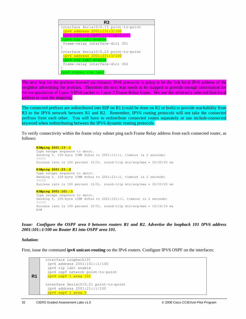
8. IPv6 Routing Section IMPORTANT! On all IPv6 routers enable the ipv6 unicast routing with the command “ipv6 unicast-routing”. Issue: Configure IPv6 addresses and IPV6 RIP routing processes ‘lab1” Solution: Before you start configuring the IPV6 routing protocols, enter ipv6 unicast-routing in global configuration mode on the IPv6 routers. Then, configure IPV6 addresses on the frame relay link between the routers R1, R2 and R3. Map the remote IPv6 addresses to the local DLCIs where it is necessary (on multipoint and physical interfaces). It is similar to IPv4, except you do not have to provide mapping for the local IPv6 addresses in order to be able to ping them. The link-local IPv6 addresses are not specified in this scenario, you are free to use the default mac-based IPv6 addresses or make them up where you want to make your frame relay mapping easier.
R1 R2 interface Loopback101 ipv6 address 2001:101::1/100 ipv6 rip lab1 enable ipv6 ospf network point-to-point ipv6 ospf 1 area 101 interface Serial0/0.13 multipoint ipv6 address 2001:13::1/100 ipv6 rip lab1 enable frame map ipv6 2001:13::3 103 broadcast frame-relay map ipv6 FE80::3 103 broadcast ! ipv6 router rip lab1 redistribute ospf 1 metric 1 include-connected
interface Serial0/0.23 point-to-point ipv6 address 2001:23::2/100 ipv6 rip lab1 enable frame-relay interface-dlci 203 ! ipv6 router rip lab1
32 CIERS Graded Assessment Labs v1.0 © 2008 Cisco CCIEXcel Pilot Program
R3
interface Serial0/0.13 point-to-point ipv6 address 2001:13::3/100 ipv6 address FE80::3 link-local ipv6 rip lab1 enable frame-relay interface-dlci 301 ! interface Serial0/0.23 point-to-point ipv6 address 2001:23::3/100 ipv6 rip lab1 enable frame-relay interface-dlci 302 ! ipv6 router rip lab1
The next hop for the prefixes learned via dynamic IPv6 protocols is going to be the link local IPv6 address of the neighbor advertising the prefixes. Therefore the next hop needs to be mapped to provide enough information for the encapsulation of Layer 3 IPv6 packet to Layer 2 Frame Relay frame. We use the arbitrarily selected link-local address to ease the mapping. The connected prefixes are redistributed into RIP on R1 (could be done on R2 or both) to provide reachability from R3 to the IPV6 network between R1 and R2. Remember, IPV6 routing protocols will not take the connected prefixes from each other. You will have to redistribute connected routes separately or use include-connected keyword when redistributing between the IPV6 dynamic routing protocols. To verify connectivity within the frame relay subnet ping each Frame Relay address from each connected router, as follows:
R3#ping 2001:13::1 Type escape sequence to abort. Sending 5, 100-byte ICMP Echos to 2001:13::1, timeout is 2 seconds: !!!!! Success rate is 100 percent (5/5), round-trip min/avg/max = 20/20/20 ms R3#ping 2001:23::2 Type escape sequence to abort. Sending 5, 100-byte ICMP Echos to 2001:23::2, timeout is 2 seconds: !!!!! Success rate is 100 percent (5/5), round-trip min/avg/max = 20/20/20 ms R3#ping 2001:101::1 Type escape sequence to abort. Sending 5, 100-byte ICMP Echos to 2001:101::1, timeout is 2 seconds: !!!!! Success rate is 100 percent (5/5), round-trip min/avg/max = 16/16/16 ms R3#
Issue: Configure the OSPF area 0 between routers R1 and R2. Advertise the loopback 101 IPV6 address 2001:101::1/100 on Router R1 into OSPF area 101. Solution: First, issue the command ipv6 unicast-routing on the IPv6 routers. Configure IPV6 OSPF on the interfaces:
R1
interface Loopback101 ipv6 address 2001:101::1/100 ipv6 rip lab1 enable ipv6 ospf network point-to-point ipv6 ospf 1 area 101 interface Serial0/0.21 point-to-point ipv6 address 2001:21::1/100 ipv6 ospf 1 area 0
© 2008 Cisco CCIExcel Pilot Program CIERS Course Introduction 33
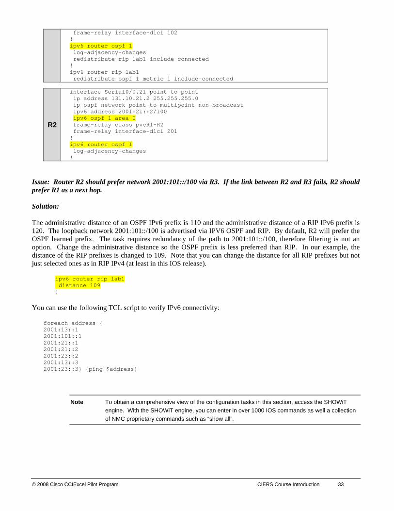
frame-relay interface-dlci 102 ! ipv6 router ospf 1 log-adjacency-changes redistribute rip lab1 include-connected ! ipv6 router rip lab1 redistribute ospf 1 metric 1 include-connected
R2
interface Serial0/0.21 point-to-point ip address 131.10.21.2 255.255.255.0 ip ospf network point-to-multipoint non-broadcast ipv6 address 2001:21::2/100 ipv6 ospf 1 area 0 frame-relay class pvcR1-R2 frame-relay interface-dlci 201 ! ipv6 router ospf 1 log-adjacency-changes !
Issue: Router R2 should prefer network 2001:101::/100 via R3. If the link between R2 and R3 fails, R2 should prefer R1 as a next hop. Solution: The administrative distance of an OSPF IPv6 prefix is 110 and the administrative distance of a RIP IPv6 prefix is 120. The loopback network 2001:101::/100 is advertised via IPV6 OSPF and RIP. By default, R2 will prefer the OSPF learned prefix. The task requires redundancy of the path to 2001:101::/100, therefore filtering is not an option. Change the administrative distance so the OSPF prefix is less preferred than RIP. In our example, the distance of the RIP prefixes is changed to 109. Note that you can change the distance for all RIP prefixes but not just selected ones as in RIP IPv4 (at least in this IOS release).
ipv6 router rip lab1 distance 109 !
You can use the following TCL script to verify IPv6 connectivity:
foreach address { 2001:13::1 2001:101::1 2001:21::1 2001:21::2 2001:23::2 2001:13::3 2001:23::3} {ping $address}
Note To obtain a comprehensive view of the configuration tasks in this section, access the SHOWiT engine. With the SHOWiT engine, you can enter in over 1000 IOS commands as well a collection of NMC proprietary commands such as “show all”.
34 CIERS Graded Assessment Labs v1.0 © 2008 Cisco CCIEXcel Pilot Program
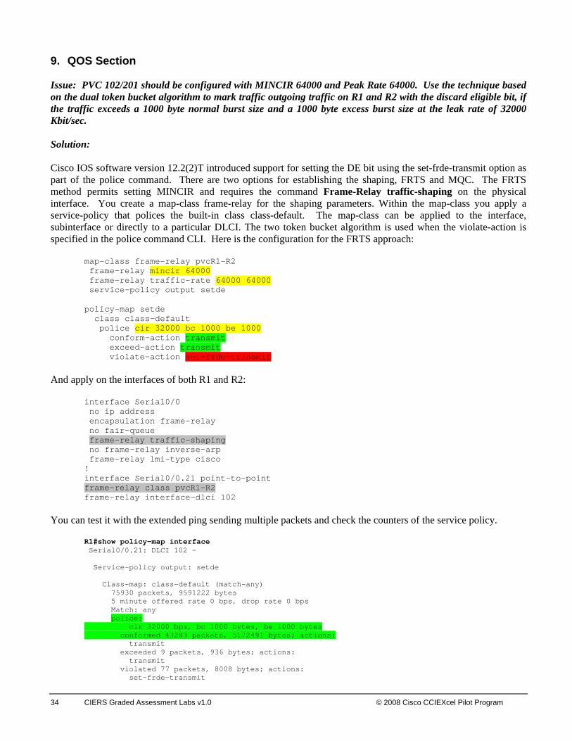
9. QOS Section Issue: PVC 102/201 should be configured with MINCIR 64000 and Peak Rate 64000. Use the technique based on the dual token bucket algorithm to mark traffic outgoing traffic on R1 and R2 with the discard eligible bit, if the traffic exceeds a 1000 byte normal burst size and a 1000 byte excess burst size at the leak rate of 32000 Kbit/sec. Solution: Cisco IOS software version 12.2(2)T introduced support for setting the DE bit using the set-frde-transmit option as part of the police command. There are two options for establishing the shaping, FRTS and MQC. The FRTS method permits setting MINCIR and requires the command Frame-Relay traffic-shaping on the physical interface. You create a map-class frame-relay for the shaping parameters. Within the map-class you apply a service-policy that polices the built-in class class-default. The map-class can be applied to the interface, subinterface or directly to a particular DLCI. The two token bucket algorithm is used when the violate-action is specified in the police command CLI. Here is the configuration for the FRTS approach:
map-class frame-relay pvcR1-R2 frame-relay mincir 64000 frame-relay traffic-rate 64000 64000 service-policy output setde policy-map setde class class-default police cir 32000 bc 1000 be 1000 conform-action transmit exceed-action transmit violate-action set-frde-transmit
And apply on the interfaces of both R1 and R2:
interface Serial0/0 no ip address encapsulation frame-relay no fair-queue frame-relay traffic-shaping no frame-relay inverse-arp frame-relay lmi-type cisco ! interface Serial0/0.21 point-to-point frame-relay class pvcR1-R2 frame-relay interface-dlci 102
You can test it with the extended ping sending multiple packets and check the counters of the service policy.
R1#show policy-map interface Serial0/0.21: DLCI 102 - Service-policy output: setde Class-map: class-default (match-any) 75930 packets, 9591222 bytes 5 minute offered rate 0 bps, drop rate 0 bps Match: any police: cir 32000 bps, bc 1000 bytes, be 1000 bytes conformed 43283 packets, 5172491 bytes; actions: transmit exceeded 9 packets, 936 bytes; actions: transmit violated 77 packets, 8008 bytes; actions: set-frde-transmit

© 2008 Cisco CCIExcel Pilot Program CIERS Course Introduction 35
conformed 0 bps, exceed 0 bps, violate 0 bps R1# R1#show fram pvc 102 PVC Statistics for interface Serial0/0 (Frame Relay DTE) DLCI = 102, DLCI USAGE = LOCAL, PVC STATUS = ACTIVE, INTERFACE = Serial0/0.21 input pkts 98176 output pkts 75939 in bytes 37287806 out bytes 9601380 dropped pkts 0 in pkts dropped 0 out pkts dropped 26 out bytes dropped 2704 late-dropped out pkts 26 late-dropped out bytes 2704 in FECN pkts 0 in BECN pkts 0 out FECN pkts 0 out BECN pkts 0 in DE pkts 21 out DE pkts 77 out bcast pkts 21751 out bcast bytes 3532953 5 minute input rate 0 bits/sec, 0 packets/sec 5 minute output rate 0 bits/sec, 0 packets/sec pvc create time 3d20h, last time pvc status changed 3d02h cir 64000 bc 64000 be 0 byte limit 1000 interval 125 mincir 64000 byte increment 1000 Adaptive Shaping none pkts 75938 bytes 9601366 pkts delayed 73 bytes delayed 7347 shaping inactive traffic shaping drops 26 service policy setde Serial0/0.21: DLCI 102 - Service-policy output: setde Class-map: class-default (match-any) 75932 packets, 9591498 bytes 5 minute offered rate 0 bps, drop rate 0 bps Match: any police: cir 32000 bps, bc 1000 bytes, be 1000 bytes conformed 43284 packets, 5172683 bytes; actions: transmit exceeded 9 packets, 936 bytes; actions: transmit violated 77 packets, 8008 bytes; actions: set-frde-transmit conformed 0 bps, exceed 0 bps, violate 0 bps Output queue size 0/max total 600/drops 26 R1#
For more information check: http://www.cisco.com/en/US/tech/tk543/tk545/technologies_tech_note09186a0080094acb.shtml
For information on traffic shaping with the MQC, try this link: http://www.cisco.com/univercd/cc/td/doc/product/software/ios122/122cgcr/fqos_c/fqcprt4/qcfcbshp.htm Issue: Send Ping traffic from SW3 to 131.10.16.6. On SW2, set the DSCP = 59 on the Ping traffic coming in on the port FA0/22. Make sure you test and see classified and DSCP=59 marked packets on SW2 Solution: We suggest read all the sections of this scenario carefully and draw out a diagram representing the traffic flow. Here is the example of such a diagram:

SW2 switch must have “mls qos” configured to turn on the QOS functionality. Here are the important steps reflecting the callout on the diagram: 1. The ICMP traffic flow from 131.10.160.7 to 131.10.16.6 is coming in on the interface 0/22 of SW2. Mark this
traffic with the DSCP 59.
mls qos ! class-map match-all ICMP-SW3-R6 match access-group 123 ! policy-map STEP-1 class ICMP-SW3-R6 set dscp 59 ! interface FastEthernet0/22 switchport access vlan 10 switchport mode access service-policy input STEP-1 mls qos monitor dscp 59 ! access-list 123 permit icmp host 131.10.160.7 host 131.10.16.6
Issue: You can test it and see classified DSCP=59 marked packets on SW2. The interface command mls qos monitor dscp 59 will instruct the switch SW2 to generate statistics for DSCP 59 on the ingress interface (on 3550 switches only, 3560 switches always monitor), which can be viewed with the following command:
SW2#show mls qos interface FA0/22 statistics FastEthernet0/22 Ingress dscp: incoming no_change classified policed dropped (in bytes)
36 CIERS Graded Assessment Labs v1.0 © 2008 Cisco CCIEXcel Pilot Program

© 2008 Cisco CCIExcel Pilot Program CIERS Course Introduction 37
59: 0 0 0 0 0 Others: 11428322 11370678 57644 0 0 Egress dscp: incoming no_change classified policed dropped (in bytes) 59: 0 n/a n/a 0 0 Others: 34869808 n/a n/a 0 0 SW2#
Verify DSCP 59 marking by pinging from SW3:
S W2#clear mls qos int fa0/22 statistics
SW2#show mls qos interface FA0/22 statistics FastEthernet0/22 Ingress dscp: incoming no_change classified policed dropped (in bytes) 59: 0 0 0 0 0 Others: 64 64 0 0 0 Egress dscp: incoming no_change classified policed dropped (in bytes) 59: 0 n/a n/a 0 0 Others: 1194 n/a n/a 0 0 SW2# SW3#ping 131.10.16.6 rep 1 size 100 Type escape sequence to abort. Sending 1, 100-byte ICMP Echos to 131.10.16.6, timeout is 2 seconds: ! Success rate is 100 percent (1/1), round-trip min/avg/max = 8/8/8 ms SW3# SW2#show mls qos interface FA0/22 statistics FastEthernet0/22 Ingress dscp: incoming no_change classified policed dropped (in bytes) 59: 0 0 118 0 0 Others: 619 501 0 0 0 Egress dscp: incoming no_change classified policed dropped (in bytes) 59: 0 n/a n/a 0 0 Others: 3982 n/a n/a 0 0 SW2#
Note: 18 bytes are added for Ethernet framing. 2. On R1 match IP traffic carrying DSCP 59 and set IP precedence 3 (flash) on the interface to R6.
class-map match-all DSCP59 match dscp 59 ! policy-map DSCP59toPREC3 class DSCP59 set ip precedence 3 ! interface FastEthernet0/0.40 encapsulation dot1Q 40 ip address 131.10.16.1 255.255.255.0 service-policy output DSCP59toPREC3
3. Make sure you trust the IP precedence on the interface FA0/1 of SW2, since SW2 is mls qos enabled it will
overwrite IP precedence. You need to preserve IP precedence 3 in the packets forwarded to R6.
interface FastEthernet0/1 switchport trunk encapsulation dot1q switchport trunk native vlan 10 switchport trunk allowed vlan 10,40 switchport mode trunk
38 CIERS Graded Assessment Labs v1.0 © 2008 Cisco CCIEXcel Pilot Program
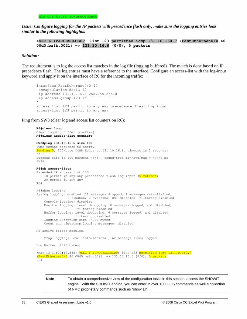
mls qos trust ip-precedence Issue: Configure logging for the IP packets with precedence flash only, make sure the logging entries look similar to the following highlights:
%SEC-6-IPACCESSLOGDP: list 123 permitted icmp 131.10.160.7 (FastEthernet0/0.40 00d0.ba8b.0021) -> 131.10.16.6 (0/0), 5 packets
Solution: The requirement is to log the access list matches in the log file (logging buffered). The match is done based on IP precedence flash. The log entries must have a reference to the interface. Configure an access-list with the log-input keyword and apply it on the interface of R6 for the incoming traffic:
interface FastEthernet0/0.40 encapsulation dot1Q 40 ip address 131.10.16.6 255.255.255.0 ip access-group 123 in ! access-list 123 permit ip any any precedence flash log-input access-list 123 permit ip any any
Ping from SW3 (clear log and access list counters on R6):
R6#clear logg Clear logging buffer [confirm] R6#clear access-list counters SW3#ping 131.10.16.6 size 100 Type escape sequence to abort. Sending 5, 100-byte ICMP Echos to 131.10.16.6, timeout is 2 seconds: !!!!! Success rate is 100 percent (5/5), round-trip min/avg/max = 4/4/8 ms SW3# R6#sh access-lists Extended IP access list 123 10 permit ip any any precedence flash log-input (5 matches) 20 permit ip any any R6# R6#show logging Syslog logging: enabled (11 messages dropped, 1 messages rate-limited, 0 flushes, 0 overruns, xml disabled, filtering disabled) Console logging: disabled Monitor logging: level debugging, 0 messages logged, xml disabled, filtering disabled Buffer logging: level debugging, 6 messages logged, xml disabled, filtering disabled Logging Exception size (4096 bytes) Count and timestamp logging messages: disabled No active filter modules. Trap logging: level informational, 62 message lines logged Log Buffer (4096 bytes): *Mar 13 11:02:14.882: %SEC-6-IPACCESSLOGDP: list 123 permitted icmp 131.10.160.7 (FastEthernet0/0.40 00d0.ba8b.0021) -> 131.10.16.6 (0/0), 5 packets R6#
Note To obtain a comprehensive view of the configuration tasks in this section, access the SHOWiT engine. With the SHOWiT engine, you can enter in over 1000 IOS commands as well a collection of NMC proprietary commands such as “show all”.

© 2008 Cisco CCIExcel Pilot Program CIERS Course Introduction 39
10. Security Section Issue: Provide the security solution allowing only routers SW3 and R6 to finger R4’s 131.10.14.4 IP address from their respective IP addresses 131.10.160.7 and 131.10.16.6. These permission entries must be created temporarily and should be removed if there are no packets on the finger sessions for 1 minute between the SW3 and R4 and 2 minutes for the finger sessions between the R6 and R4. Router R4 must not be able to finger to any router behind R1, including router R1 as well. The provided security solution should not be limited only to TCP types of traffic. Solution: This task requires us to allow TCP/IP session establishment from SW3 and R6 to R4 and disallow TCP/IP session establishment in the opposite direction. Two techniques come to mind: an access list with the keyword established, and reflexive access lists. Reflexive access list are more advanced, they create a temporary entry for each session and remove that entry if the session is idle for the specified timeout. Since there is a requirement to configure a timeout in this exam, a reflexive access list will be used to solve this security issue. See the diagram below.
Imagine that SW3 and R6 are on the internal network and R4 is on the external network. For this example the reflexive access list configuration will be applied on the external interface, which is R1’s virtual-template interface, connected to R4. Issue: The scenario requires configuration of different timeouts. Solution: The timeouts can be configured per evaluated sessions. Lets look at the following configuration: 1. interface Virtual-Template1 2. ip address 131.10.14.1 255.255.255.0 3. ip access-group INBOUND in 4. ip access-group OUTBOUND out 5. ip access-list extended INBOUND 6. permit tcp any any eq bgp
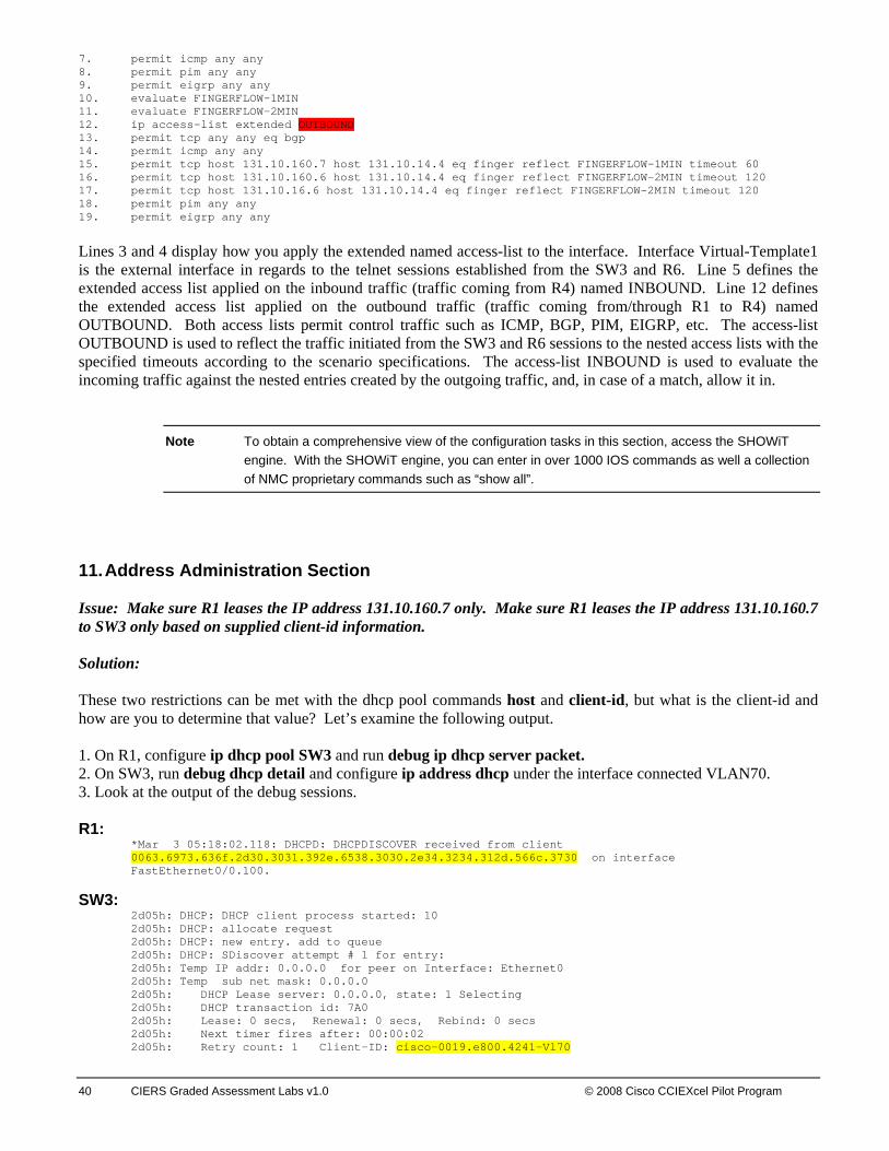
40 CIERS Graded Assessment Labs v1.0 © 2008 Cisco CCIEXcel Pilot Program
7. permit icmp any any 8. permit pim any any 9. permit eigrp any any 10. evaluate FINGERFLOW-1MIN 11. evaluate FINGERFLOW-2MIN 12. ip access-list extended OUTBOUND 13. permit tcp any any eq bgp 14. permit icmp any any 15. permit tcp host 131.10.160.7 host 131.10.14.4 eq finger reflect FINGERFLOW-1MIN timeout 60 16. permit tcp host 131.10.160.6 host 131.10.14.4 eq finger reflect FINGERFLOW-2MIN timeout 120 17. permit tcp host 131.10.16.6 host 131.10.14.4 eq finger reflect FINGERFLOW-2MIN timeout 120 18. permit pim any any 19. permit eigrp any any
Lines 3 and 4 display how you apply the extended named access-list to the interface. Interface Virtual-Template1 is the external interface in regards to the telnet sessions established from the SW3 and R6. Line 5 defines the extended access list applied on the inbound traffic (traffic coming from R4) named INBOUND. Line 12 defines the extended access list applied on the outbound traffic (traffic coming from/through R1 to R4) named OUTBOUND. Both access lists permit control traffic such as ICMP, BGP, PIM, EIGRP, etc. The access-list OUTBOUND is used to reflect the traffic initiated from the SW3 and R6 sessions to the nested access lists with the specified timeouts according to the scenario specifications. The access-list INBOUND is used to evaluate the incoming traffic against the nested entries created by the outgoing traffic, and, in case of a match, allow it in.
Note To obtain a comprehensive view of the configuration tasks in this section, access the SHOWiT engine. With the SHOWiT engine, you can enter in over 1000 IOS commands as well a collection of NMC proprietary commands such as “show all”.
11. Address Administration Section Issue: Make sure R1 leases the IP address 131.10.160.7 only. Make sure R1 leases the IP address 131.10.160.7 to SW3 only based on supplied client-id information. Solution: These two restrictions can be met with the dhcp pool commands host and client-id, but what is the client-id and how are you to determine that value? Let’s examine the following output. 1. On R1, configure ip dhcp pool SW3 and run debug ip dhcp server packet. 2. On SW3, run debug dhcp detail and configure ip address dhcp under the interface connected VLAN70. 3. Look at the output of the debug sessions. R1:
*Mar 3 05:18:02.118: DHCPD: DHCPDISCOVER received from client 0063.6973.636f.2d30.3031.392e.6538.3030.2e34.3234.312d.566c.3730 on interface FastEthernet0/0.100.
SW3: 2d05h: DHCP: DHCP client process started: 10 2d05h: DHCP: allocate request 2d05h: DHCP: new entry. add to queue 2d05h: DHCP: SDiscover attempt # 1 for entry: 2d05h: Temp IP addr: 0.0.0.0 for peer on Interface: Ethernet0 2d05h: Temp sub net mask: 0.0.0.0 2d05h: DHCP Lease server: 0.0.0.0, state: 1 Selecting 2d05h: DHCP transaction id: 7A0 2d05h: Lease: 0 secs, Renewal: 0 secs, Rebind: 0 secs 2d05h: Next timer fires after: 00:00:02 2d05h: Retry count: 1 Client-ID: cisco-0019.e800.4241-Vl70
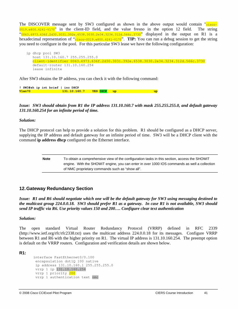
© 2008 Cisco CCIExcel Pilot Program CIERS Course Introduction 41
The DISCOVER message sent by SW3 configured as shown in the above output would contain "cisco-0019.e800.4241-Vl70" in the client-ID field, and the value fresno in the option 12 field. The string “0063.6973.636f.2d30.3031.392e.6538.3030.2e34.3234.312d.566c.3730” displayed in the output on R1 is a hexadecimal representation of “cisco-0019.e800.4241-Vl70”. TIP: You can run a debug session to get the string you need to configure in the pool. For this particular SW3 lease we have the following configuration:
ip dhcp pool SW3 host 131.10.160.7 255.255.255.0 client-identifier 0063.6973.636f.2d30.3031.392e.6538.3030.2e34.3234.312d.566c.3730 default-router 131.10.160.254 lease infinite
After SW3 obtains the IP address, you can check it with the following command: ! SW3#sh ip int brief | inc DHCP Vlan70 131.10.160.7 YES DHCP up up
Issue: SW3 should obtain from R1 the IP address 131.10.160.7 with mask 255.255.255.0, and default gateway 131.10.160.254 for an infinite period of time. Solution: The DHCP protocol can help to provide a solution for this problem. R1 should be configured as a DHCP server, supplying the IP address and default gateway for an infinite period of time. SW3 will be a DHCP client with the command ip address dhcp configured on the Ethernet interface.
Note To obtain a comprehensive view of the configuration tasks in this section, access the SHOWiT engine. With the SHOWiT engine, you can enter in over 1000 IOS commands as well a collection of NMC proprietary commands such as “show all”.
12. Gateway Redundancy Section Issue: R1 and R6 should negotiate which one will be the default gateway for SW3 using messaging destined to the multicast group 224.0.0.18. SW3 should prefer R1 as a gateway. In case R1 is not available, SW3 should send IP traffic via R6. Use priority values 150 and 200…. Configure clear text authentication Solution: The open standard Virtual Router Redundancy Protocol (VRRP) defined in RFC 2339 (http://www.ietf.org/rfc/rfc2338.txt) uses the multicast address 224.0.0.18 for its messages. Configure VRRP between R1 and R6 with the higher priority on R1. The virtual IP address is 131.10.160.254. The preempt option is default on the VRRP routers. Configuration and verification details are shown below. R1:
interface FastEthernet0/0.100 encapsulation dot1Q 100 native ip address 131.10.160.1 255.255.255.0 vrrp 1 ip 131.10.160.254 vrrp 1 priority 200 vrrp 1 authentication text nmc

42 CIERS Graded Assessment Labs v1.0 © 2008 Cisco CCIEXcel Pilot Program
R6: interface FastEthernet0/0.100 encapsulation dot1Q 100 native ip address 131.10.160.6 255.255.255.0 vrrp 1 ip 131.10.160.254 vrrp 1 priority 150 vrrp 1 authentication text nmc
R1#show vrrp all FastEthernet0/0.100 - Group 1 State is Master Virtual IP address is 131.10.160.254 Virtual MAC address is 0000.5e00.0101 Advertisement interval is 1.000 sec Preemption is enabled min delay is 0.000 sec Priority is 200 Authentication is enabled Master Router is 131.10.160.6, priority is 150 Master Advertisement interval is 1.000 sec Master Down interval is 3.609 sec (expires in 3.549 sec)
R6#show vrrp all FastEthernet0/0.100 - Group 1 State is Backup Virtual IP address is 131.10.160.254 Virtual MAC address is 0000.5e00.0101 Advertisement interval is 1.000 sec Preemption is enabled min delay is 0.000 sec Priority is 150 Authentication is enabled Master Router is 131.10.160.6 (local), priority is 200 Master Advertisement interval is 1.000 sec Master Down interval is 3.414 sec
Since SW3 simulates an IP host, its routing table will show the default gateway only:
SW3#show ip route Default gateway is 131.10.160.254 Host Gateway Last Use Total Uses Interface ICMP redirect cache is empty SW3#
Note To obtain a comprehensive view of the configuration tasks in this section, access the SHOWiT engine. With the SHOWiT engine, you can enter in over 1000 IOS commands as well a collection of NMC proprietary commands such as “show all”.
13. Multicast Section
Issue: Configure multicast traffic distribution based on a push technology. Solution: IP PIM Dense mode uses a push technology for traffic distribution. Traffic is flooded out all interfaces on which there is a PIM neighbor or a client, other than the rpf interface. This is unlike PIM Sparse mode, which can be described as a “pull” technology, based on explicit joins. Configure ip pim dense-mode on all the interfaces specified in the scenario only.

© 2008 Cisco CCIExcel Pilot Program CIERS Course Introduction 43
Issue: Do not configure PIM relationship on non-specified links. Solution: This requirement creates an issue with the RPF lookup back to the source of the multicast ping. The multicast pings are sourced from R4 by the scenario specifications. Look at the diagram displaying the RPF interfaces and the issues created by IGP configuration:
R4R1
R3
R2
R5
ping 232.2.2.2S=131.10.14.4
PIM Dense
RPF Interface for 131.10.14.4PROBLEM
R1 needs PIM configuration on its incoming interface to process the multicast packets; R1 will not form any PIM relationship with R4. The RPF interface for the source IP address 131.10.14.4 on R2 is the interface connected to R1, because of the OSPF path calculation. The OSPF cost of the link between R1 and R2 is lower than the cost of the link between R2 and R3. Therefore the default RPF interface is on the links R2 and R1. R2 will not accept the multicast traffic from R3. The RPF interface for the source IP address 131.10.14.4 on R5 is the interface connected to R3, because of the OSPF path calculation. R5 will not accept the multicast traffic from R2. You have two options: 1) Modify the IGP configuration to adjust the RPF interfaces 2) Use the ip mroute command to adjust the RPF interfaces. The second option is used as a solution. Look at the following diagram with the correct placement of the RPF interfaces:

44 CIERS Graded Assessment Labs v1.0 © 2008 Cisco CCIEXcel Pilot Program
R1#show ip rpf 131.10.14.4 RPF information for ? (131.10.14.4) RPF interface: Virtual-Access1 RPF neighbor: ? (131.10.14.4) - directly connected RPF route/mask: 131.10.14.4/32 RPF type: unicast (connected) RPF recursion count: 0 Doing distance-preferred lookups across tables R1# R3#show ip route | inc 131.10.14.4 D 131.10.14.4/32 [90/4729856] via 131.10.13.1, 1d00h, Serial0/0.13 R3# R3#show ip rpf 131.10.14.4 RPF information for ? (131.10.14.4) RPF interface: Serial0/0.13 RPF neighbor: ? (131.10.13.1) RPF route/mask: 131.10.14.4/32 RPF type: unicast (eigrp 300) RPF recursion count: 0 Doing distance-preferred lookups across tables R3# R2#show ip route | inc 131.10.14.4 O E2 131.10.14.4/32 [110/20] via 131.10.21.1, 00:26:55, Serial0/0.21 R2#show ip mroute static Mroute: 131.10.14.4/32, interface: Serial0/0.23 Protocol: none, distance: 0, route-map: none R2# R2#show ip rpf 131.10.14.4 RPF information for ? (131.10.14.4) RPF interface: Serial0/0.23 RPF neighbor: ? (131.10.23.0) RPF route/mask: 131.10.14.4/32 RPF type: static RPF recursion count: 0 Doing distance-preferred lookups across tables R2# R5#show ip route | inc 131.10.14.4 O E2 131.10.14.4/32 [110/20] via 131.10.35.3, 00:29:09, FastEthernet0/0.20 R5# R5#show ip mroute static Mroute: 131.10.14.4/32, RPF neighbor: 131.10.25.0 Protocol: none, distance: 0, route-map: none R5# R5#show ip rpf 131.10.14.4 RPF information for ? (131.10.14.4) RPF interface: FastEthernet0/0.50 RPF neighbor: ? (131.10.25.0) RPF route/mask: 131.10.14.4/32 RPF type: static RPF recursion count: 0 Doing distance-preferred lookups across tables R5#
Note To obtain a comprehensive view of the configuration tasks in this section, access the SHOWiT engine. With the SHOWiT engine, you can enter in over 1000 IOS commands as well a collection of NMC proprietary commands such as “show all”.
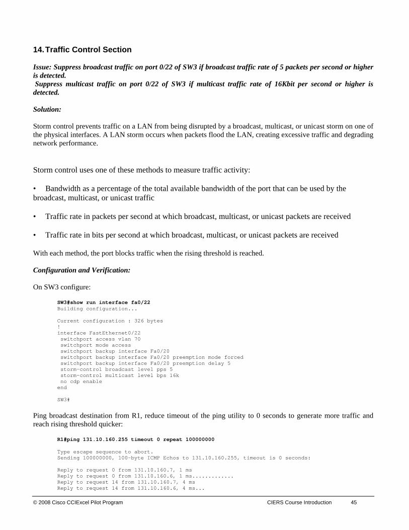
© 2008 Cisco CCIExcel Pilot Program CIERS Course Introduction 45
14. Traffic Control Section Issue: Suppress broadcast traffic on port 0/22 of SW3 if broadcast traffic rate of 5 packets per second or higher is detected. Suppress multicast traffic on port 0/22 of SW3 if multicast traffic rate of 16Kbit per second or higher is detected. Solution: Storm control prevents traffic on a LAN from being disrupted by a broadcast, multicast, or unicast storm on one of the physical interfaces. A LAN storm occurs when packets flood the LAN, creating excessive traffic and degrading network performance.
Storm control uses one of these methods to measure traffic activity:
• Bandwidth as a percentage of the total available bandwidth of the port that can be used by the broadcast, multicast, or unicast traffic
• Traffic rate in packets per second at which broadcast, multicast, or unicast packets are received
• Traffic rate in bits per second at which broadcast, multicast, or unicast packets are received
With each method, the port blocks traffic when the rising threshold is reached. Configuration and Verification: On SW3 configure:
SW3#show run interface fa0/22 Building configuration... Current configuration : 326 bytes ! interface FastEthernet0/22 switchport access vlan 70 switchport mode access switchport backup interface Fa0/20 switchport backup interface Fa0/20 preemption mode forced switchport backup interface Fa0/20 preemption delay 5 storm-control broadcast level pps 5 storm-control multicast level bps 16k no cdp enable end SW3#
Ping broadcast destination from R1, reduce timeout of the ping utility to 0 seconds to generate more traffic and reach rising threshold quicker:
R1#ping 131.10.160.255 timeout 0 repeat 100000000 Type escape sequence to abort. Sending 100000000, 100-byte ICMP Echos to 131.10.160.255, timeout is 0 seconds: Reply to request 0 from 131.10.160.7, 1 ms Reply to request 0 from 131.10.160.6, 1 ms............. Reply to request 14 from 131.10.160.7, 4 ms Reply to request 14 from 131.10.160.6, 4 ms...

46 CIERS Graded Assessment Labs v1.0 © 2008 Cisco CCIEXcel Pilot Program
Reply to request 18 from 131.10.160.7, 4 ms Reply to request 18 from 131.10.160.6, 4 ms....... Reply to request 26 from 131.10.160.6, 4 ms
On SW3 check the status of the port 0/22:
SW3#show storm-control broadcast Interface Filter State Upper Lower Current --------- ------------- ----------- ----------- ---------- Fa0/22 Blocking 5 pps 5 pps 10 pps SW3#show storm-control broadcast Interface Filter State Upper Lower Current --------- ------------- ----------- ----------- ---------- Fa0/22 Blocking 5 pps 5 pps 10 pps SW3#show storm-control broadcast Interface Filter State Upper Lower Current --------- ------------- ----------- ----------- ---------- Fa0/22 Forwarding 5 pps 5 pps 0 pps SW3#show storm-control broadcast Interface Filter State Upper Lower Current --------- ------------- ----------- ----------- ---------- Fa0/22 Blocking 5 pps 5 pps 6 pps SW3# SW3# 05:12:49: %STORM_CONTROL-3-FILTERED: A Broadcast storm detected on Fa0/22. A packet filter action has been applied on the interface.
Ping multicast destination from R1, reduce timeout of the ping utility to 0 seconds to generate more traffic and reach rising threshold quicker:
R1#ping 224.0.0.1 timeout 0 repeat 100000000 Type escape sequence to abort. Sending 100000000, 100-byte ICMP Echos to 224.0.0.1, timeout is 0 seconds: Reply to request 0 from 131.10.101.1, 4 ms Reply to request 1 from 131.10.101.1, 4 ms Reply to request 2 from 131.10.101.1, 1 ms Reply to request 3 from 131.10.101.1, 4 ms Reply to request 4 from 131.10.101.1, 1
On SW3 check the status of the port 0/22:
SW3#show storm-control multicast Interface Filter State Upper Lower Current --------- ------------- ----------- ----------- ---------- Fa0/22 Blocking 16k bps 16k bps 24.78k bps SW3#show storm-control multicast Interface Filter State Upper Lower Current --------- ------------- ----------- ----------- ---------- Fa0/22 Forwarding 16k bps 16k bps 656 bps SW3#show storm-control multicast Interface Filter State Upper Lower Current --------- ------------- ----------- ----------- ---------- Fa0/22 Blocking 16k bps 16k bps 26.57k bps SW3#show storm-control multicast Interface Filter State Upper Lower Current --------- ------------- ----------- ----------- ---------- Fa0/22 Blocking 16k bps 16k bps 26.64k bps SW3# 05:14:22: %STORM_CONTROL-3-FILTERED: A Multicast storm detected on Fa0/22. A packet filter action has been applied on the interface. SW3#
Note To obtain a comprehensive view of the configuration tasks in this section, access the SHOWiT engine. With the SHOWiT engine, you can enter in over 1000 IOS commands as well a collection of NMC proprietary commands such as “show all”.