cimentaciones de torres
TRANSCRIPT
There has been an increasing trend of construc-tion of microwave communication and transmis-sion line towers all over the country. The founda-tions of such towers constitute nearly 20 to 40percent of the total cost of towers. However, verylittle information is available on the design pro-cedure of tower foundation. The paper presentsthe underlying concepts for designing tower foun-dations efficiently and economically. A computerprogram in BASIC, which uses these concepts,is also presented. This program may be used tooptimally proportion the tower foundations.
N. $Orarnarf and V. Vaser01
Transmission line towers, antenna towers, towers used foroil well derricks and mine-shaft equipment, beacon supports.and observation platform, etc., are examples of self-supportingtowers. Out of these various types of towers, transmissionline towers are subjected to torsional forces, in addition toother forces.
Normally, the tower foundation constitutes about 20 to 40percent of the total cost of tower. A rough idea about thiscost could be obtained from the relative weights of the founda-tion and tower. It was observed that for a 100-m high micro-wave tower, the weight of the foundation concrete wasaround 410t, while the weight of the structural steel of thetower was only 65t. From the engineering point of view, thefoundation design of towers poses a serious problem due todifferent types of soils encountered and also due to thevarious forces acting on the foundation. Thus, the structuralengineer is faced with a difficult task of producing econo-mical and reliable design'. A very little information is avai-lable for the design of such foundations 1-3 ' 5-8
The design of tower foundation is basically an interativeprocedure. Since the uplift force is predominant, the designposes a number of problems, and hence, is amenable tocomputerization. However, till now, no program is availablein India for the design of these foundations. In this paper acomputer program is presented, based on the provisions ofthe recent Indian Codes of Practice 2 ' 3 ' 4 . A brief outline of theprocedure to be used for the design of tower foundations isalso described. Salient features of the package developed,baked on this procedure are enumerated. The package hasbeen developed using the BASIC language for use on anIBM PC or compatible machine based on the working stressmethod of design. Both unreinforced and reinforced concrete
Dr. N. Subramanian, Chief Executive, Computer Design Consultants, 191North Usman Road, T. Nagar, Madras 600 017.
Ms V. Vasanthi, Assistant Manager, Computer Design Consultants,Madras 600 017.
Design oftowerfoundations
sections could be designed by using this program. Differenttypes of soil conditions, viz., normal dry, wet, submerged,partially submerged. black cotton, wet black cotton, soft rock,and hard rock, are considered. Based on this procedure, theauthors have designed a 100-m microwave tower foundationwhich was executed by the Indian Telephone Industries inRajasthan.
DesignThere are two parts in the design. They are: stability analysis,and strength design. Stability analysis aims at removing thepossibility of failure by overturning, uprooting, sliding andtilting of the foundation due to soil pressure being in excessof the ultimate capacity of the soil. The strength design con-sists of proportioning the components of the foundation tothe respective maximum moment, shear, pull and thrust orcombination of the same.
The type of loading that controls the foundation designdepends mainly on the kind of towers being designed. Thecontrolling design loads for four-legged lattice towers arevertical uplift, compression and side thrust.
Depending on the site condition and the forces acting onthe tower legs, one of the following types of foundation isnormally employed:
(i) drilled and/or belled shaft(ii) pad and chimney
(iii) footing with undercut(iv) auger with reaming(v) grillage(vi) special type.
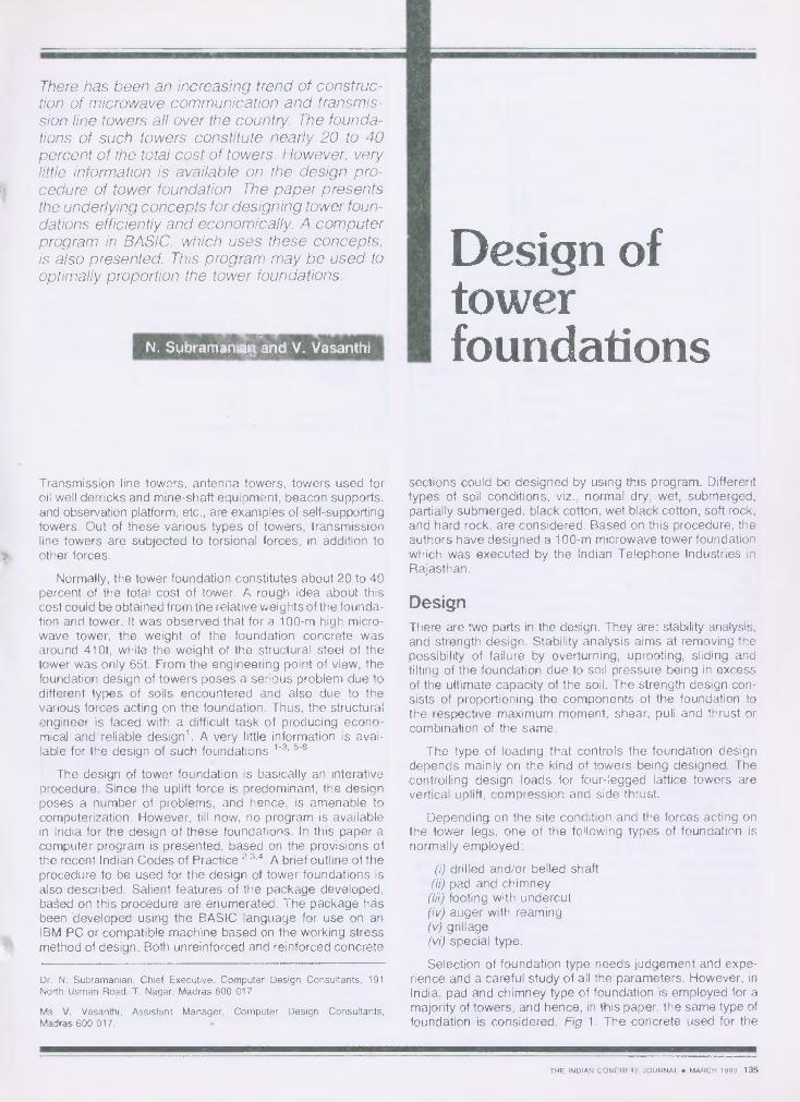
Selection of foundation type needs judgement and expe-rience and a careful study of all the parameters. However, inIndia, pad and chimney type of foundation is employed for amajority of towers, and hence, in this paper, the same type offoundation is considered, Fig 1. The concrete used for the
THE INDIAN CONCRETE JOURNAL ♦ MARCH 1990 135
Base plate
t _7
•
94 ,94w
T.Anchor bolts
T
tiStub angle
B1
TtiC
• Chimney• reinforcement
WNW -•
x
1 4_Chimney-pad type foundation Reinforced concrete foundation
(a) lb)
( C ) (d)
Stub angle
813
Benching of hard rock
– Mors — Earthcone
Balla —••-- Coulomb shear friction
Matsuo
Meyerhof and Adams
5000 300C, psf
30° 20°
0, degree
100
./.
*N.10
Tw
L
c,
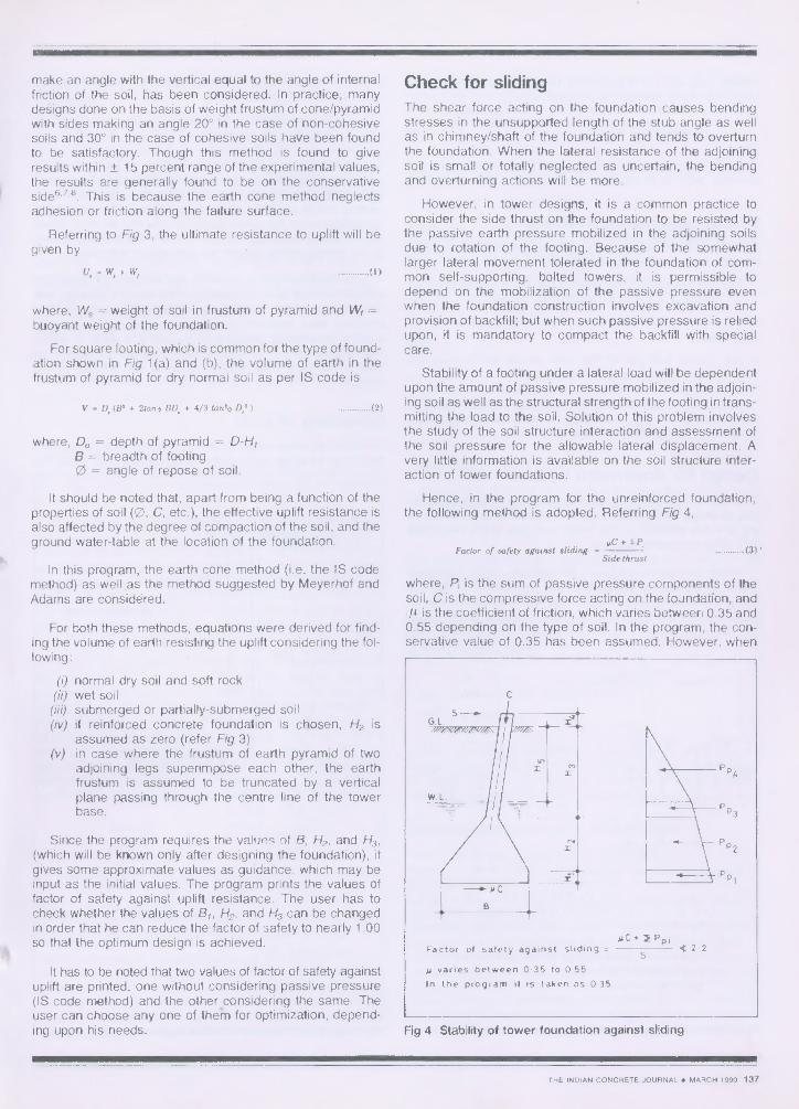
H1 = 50mm
H4 225mm
H5 = 750 mm for partiallysubmerged soil
H5 1.50m for wet soil
H5 = 750mm for wet soft rock
H5 .0 for dry soil
Fig 1 Different types of tower foundation
foundation is assumed to be of grade M-15 corresponding to1:2:4 nominal mix with 20mm coarse aggregate for chimneyportion and 40mm coarse aggregate for pyramid or slabportion. When reinforced concrete foundation is adopted, theentire footing is assumed to be made of 20mm coarseaggregate .
Design for uplift resistanceApart from resisting the vertical compression, the soil surroun-ding a tower foundation has also to resist a considerableamount of upward pull and side thrust. As a matter of fact,the available uplift resistance of the soil is the deciding factorin selecting the size of the footing. However, unfortunately,adequate theory has not yet been established for theaccurate assessment of the uplift resistance of the soil mass.It is generally considered that the resistance to uplift is pro-vided by the shed, strength of the soil and the weight of thefoundation. Various empirical relationships linking ultimateholding power to the physical properties of the soil, as wellas the dimensions of the footing have been proposed on thebasis of experimental results 5 .
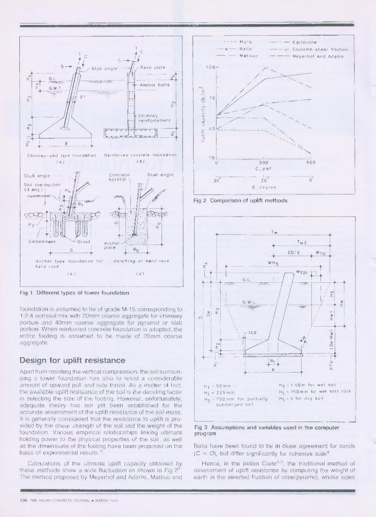
Calculations of the ultimate uplift capacity obtained bythese methods show a wide fluctuation as shown in Fig 2'.The method proposed by Meyerhof and Adams, Matsuo and
Fig 2 Comparison of uplift methods
Fig 3 Assumptions and variables used in the computerprogram
Balla have been found to be in close agreement for sands(C = 0), but differ significantly for cohesive soils 4 .
Hence, in the Indian Code2 . 3 , the traditional method ofassessment of uplift resistance by computing the weight ofearth in the inverted frustum of cone/pyramid, whose sides
136 THE INDIAN CONCRETE JOURNAL ♦ MARCH 1990
P
P p3
P
-2
4
C
B
(IC • M Pp,Factor of safety against sliding _ 22
5varies between 0.35 to 0.55
In the program it is taken as 0-35
make an angle with the vertical equal to the angle of internalfriction of the soil, has been considered. In practice, manydesigns done on the basis of weight frustum of cone/pyramidwith sides making an angle 20° in the case of non-cohesivesoils and 30° in the case of cohesive soils have been foundto be satisfactory. Though this method is found to giveresults within ± 15 percent range of the experimental values,the results are generally found to be on the conservativeside6 • 78 . This is because the earth cone method neglectsadhesion or friction along the failure surface.
Referring to Fig 3, the ultimate resistance to uplift will begiven by
U. W. W, (1)
where, Ws weight of soil in frustum of pyramid and 14/, =buoyant weight of the foundation.
For square footing, which is common for the type of found-ation shown in Fig 1(a) and (b), the volume of earth in thefrustum of pyramid for dry normal soil as per IS code is
V • D.(133 + 2tanb BD. + 4/3 tan'+ ) (2)
where, Do = depth of pyramid =B = breadth of footing0 = angle of repose of soil.
It should be noted that, apart from being a function of theproperties of soil (0, C, etc.), the effective uplift resistance isalso affected by the degree of compaction of the soil, and theground water-table at the location of the foundation.
In this program, the earth cone method (i.e. the IS codemethod) as well as the method suggested by Meyerhof andAdams are considered.
For both these methods, equations were derived for find-ing the volume of earth resisting the uplift considering the fol-lowing:
normal dry soil and soft rockwet soilsubmerged or partially-submerged soilif reinforced concrete foundation is chosen, H2 isassumed as zero (refer Fig 3)in case where the frustum of earth pyramid of twoadjoining legs superimpose each other, the earthfrustum is assumed to be truncated by a verticalplane passing through the centre line of the towerbase.
Since the program requires the values of B, H2, and H3,(which will be known only after designing the foundation), itgives some approximate values as guidance, which may beinput as the initial values. The program prints the values offactor of safety against uplift resistance. The user has tocheck whether the values of B,, H2, and H3 can be changedin order that he can reduce the factor of safety to nearly 1.00so that the optimum design is achieved.
It has to be noted that two values of factor of safety againstuplift are printed, one without considering passive pressure(IS code method) and the other considering the same. Theuser can choose any one of them for optimization, depend-ing upon his needs.
Check for slidingThe shear force acting on the foundation causes bendingstresses in the unsupported length of the stub angle as wellas in chimney/shaft of the foundation and tends to overturnthe foundation. When the lateral resistance of the adjoiningsoil is small or totally neglected as uncertain, the bendingand overturning actions will be more.
However, in tower designs, it is a common practice toconsider the side thrust on the foundation to be resisted bythe passive earth pressure mobilized in the adjoining soilsdue to rotation of the footing. Because of the somewhatlarger lateral movement tolerated in the foundation of com-mon self-supporting, bolted towers, it is permissible todepend on the mobilization of the passive pressure evenwhen the foundation construction involves excavation andprovision of backfill; but when such passive pressure is reliedupon, it is mandatory to compact the backfill with specialcare.
Stability of a footing under a lateral load will be dependentupon the amount of passive pressure mobilized in the adjoin-ing soil as well as the structural strength of the footing in trans-mitting the load to the soil. Solution of this problem involvesthe study of the soil structure interaction and assessment ofthe soil pressure for the allowable lateral displacement. Avery little information is available on the soil structure inter-action of tower foundations.
Hence, in the program for the unreinforced foundation,the following method is adopted. Referring Fig 4,
+ IP.
Factor of safety against sliding (3) *
Side thrust
where, Pi is the sum of passive pressure components of thesoil, C is the compressive force acting on the foundation, and
is the coefficient of friction, which varies between 0.35 and0.55 depending on the type of soil. In the program, the con-servative value of 0.35 has been assumed. However, when
Fig 4 Stability of tower foundation against sliding
THE INDIAN CONCRETE JOURNAL ♦ MARCH 1990 137
pp4
pp3
Pp 2
Pn 11-•
568 8/6
For stability against overturning
/Factor of safety -
(W2/2)5 613 4 2 2
(T - Wf ) 8 /3 • S(D e • H4 ) -E Pp; L a i
Where W2 Weight of soil in the cone pyramid for stability
T Uplift on the leg of tower
S. Maximum horizontal shear on tower leg
Wf .• Weight of footing
P p ; Passive pressure
Stub angle
1 I31_4
Section A-A
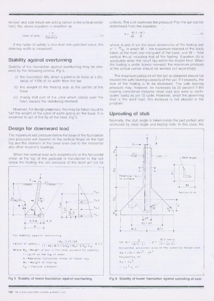
y 13/2 tan cctan a .
(13/2 - y) (1 • tan a )
horizontal projected area of the potential failure cone,
Ap ( 2y • dh ) 2 - dh 2
Neglecting dh,
Ap 4y 2
4 y 2 r c > T
CNI
13/2
tension and side thrust are acting (which is the critical condi-tion), the above equation is rewritten as
uniform. The unit maximum toe pressure P on the soil can bedetermined from the equation:
E P,Factor of safety (4)
Side thrustP.
W(1 fie')— —AB B
(5)
If the factor of safety is less than the specified value, thechimney width is increased.
Stability against overturningStability of the foundation against overturning may be che-cked by the following criteria, Fig 5,:
(i) the foundation tilts about a point in its base at a dis-tance of 1/6th of its width from the toe
(ii) the weight of the footing acts at the centre of thebase
(iii) mainly that part of the cone which stands over theheel, causes the stabilising moment.
However, for design purposes, this may be taken equal tohalf the weight of the cone of earth acting on the base. It isassumed to act at the tip of the heel, Fig 5.
Design for downward loadThe maximum soil pressure below the base of the foundation(toe pressure) will depend on the vertical thrust on the footing and the moment at the base level due to the horizontaland other eccentric loadings.
When the vertical load acts eccentrically or the horizontalshear at the top of the pedestal is transferred to the soilbelow the footing, the soil pressure at this level will not be
Fig 5 Stability of tower foundation against overturning
where A and B are the base dimensions of the footing ande' =- %, in which M = the maximum moment of the loadstaken at the level and mid point of the base, and W = totalvertical thrust including that of the footing. Equation (5) isapplicable when the result lies within the middle third. Whenthe footing is under biaxial moment, the maximum pressureat the critical corner should be worked out accordingly.
The maximum pressure on the soil so obtained should notexceed the safe bearing capacity of the soil. If it exceeds, thesize of the footing is to be increased. The safe bearingpressure may, however, be increased by 25 percent if theloading considered includes dead load and wind or earth-quake loads as per IS code. However, since the governingload is the wind load, this increase is not allowed in theprogram.
Uprooting of stubNormally, the stub angle is taken inside the pad portion andanchored by cleat angle and keying rods. In this case, the
Fig 6 Stability of tower foundation against uprooting of stub
138 THE INDIAN CONCRETE JOURNAL ♦ MARCH 1990
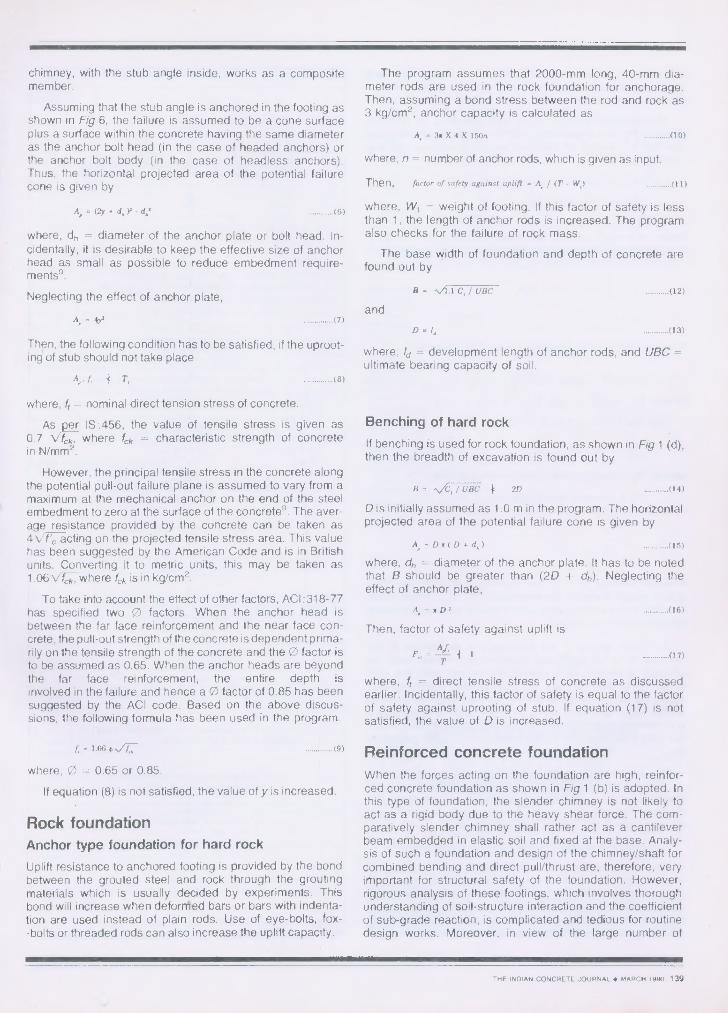
chimney, with the stub angle inside, works as a compositemember.
Assuming that the stub angle is anchored in the footing asshown in Fig 6, the failure is assumed to be a cone surfaceplus a surface within the concrete having the same diameteras the anchor bolt head (in the case of headed anchors) orthe anchor bolt body (in the case of headless anchors).Thus, the horizontal projected area of the potential failurecone is given by
A, = (2y + d, )2. d,' (6)
where, dh = diameter of the anchor plate or bolt head. In-cidentally, it is desirable to keep the effective size of anchorhead as small as possible to reduce embedment require-ments9 .
Neglecting the effect of anchor plate,
A, = (7)
Then, the following condition has to be satisfied, if the uproot-ing of stub should not take place
A,. f 4 T, (8)
where, ft = nominal direct tension stress of concrete.
As per IS :456, the value of tensile stress is given as0.7 Vf,k, where fek = characteristic strength of concretein N/mm2 .
However, the principal tensile stress in the concrete alongthe potential pull-out failure plane is assumed to vary from amaximum at the mechanical anchor on the end of the steelembedment to zero at the surface of the concretes . The aver-age resistance provided by the concrete can be taken as4 VP, acting on the projected tensile stress area. This valuehas been suggested by the American Code and is in Britishunits. Converting it to metric units, this may be taken as1.06Vfck , where fck is in kg/cm2 .
To take into account the effect of other factors, ACI :318-77has specified two 0 factors. When the anchor head isbetween the far face reinforcement and the near face con-crete, the pull-out strength of the concrete is dependent prima-rily on the tensile strength of the concrete and the 0 factor isto be assumed as 0.65. When the anchor heads are beyondthe far face reinforcement, the entire depth isinvolved in the failure and hence a 0 factor of 0.85 has beensuggested by the ACI code. Based on the above discus-sions, the following formula has been used in the program.
%/LT (9)
where, 0 = 0.65 or 0.85.
If equation (8) is not satisfied, the value of y is increased.
Rock foundationAnchor type foundation for hard rock
Uplift resistance to anchored footing is provided by the bondbetween the grouted steel and rock through the groutingmaterials which is usually decided by experiments. Thisbond will increase when deformed bars or bars with indenta-tion are used instead of plain rods. Use of eye-bolts, fox--bolts or threaded rods can also increase the uplift capacity.
The program assumes that 2000-mm long, 40-mm dia-meter rods are used in the rock foundation for anchorage.Then, assuming a bond stress between the rod and rock as3 kg/cm 2 , anchor capacity is calculated as
where, n = number of anchor rods, which is given as input.
where, Wi = weight of footing. If this factor of safety is lessthan 1, the length of anchor rods is increased. The programalso checks for the failure of rock mass.
The base width of foundation and depth of concrete arefound out by
and
where, Id = development length of anchor rods, and UBC =ultimate bearing capacity of soil.
Benching of hard rock
If benching is used for rock foundation, as shown in Fig 1 (d),then the breadth of excavation is found out by
B / UBC 2D (14)
D is initially assumed as 1.0 m in the program. The horizontalprojected area of the potential failure cone is given by
A,=Dir(D+d,) (15)
where, dh = diameter of the anchor plate. It has to be notedthat B should be greater than (2D + dh). Neglecting theeffect of anchor plate,
Then, factor of safety against uplift isA,f,
F., — I 1T
where, ft = direct tensile stress of concrete as discussedearlier. Incidentally, this factor of safety is equal to the factorof safety against uprooting of stub. If equation (17) is notsatisfied, the value of D is increased.
Reinforced concrete foundationWhen the forces acting on the foundation are high, reinfor-ced concrete foundation as shown in Fig 1 (b) is adopted. Inthis type of foundation, the slender chimney is not likely toact as a rigid body due to the heavy shear force. The com-paratively slender chimney shall rather act as a cantileverbeam embedded in elastic soil and fixed at the base. Analy-sis of such a foundation and design of the chimney/shaft forcombined bending and direct pull/thrust are, therefore, veryimportant for structural safety of the foundation. However,rigorous analysis of these footings, which involves thoroughunderstanding of soil-structure interaction and the coefficientof sub-grade reaction, is complicated and tedious for routinedesign works. Moreover, in view of the large number of
(Input: Ultimate tension, compression, shea77type of soil and its particulars j
H2
Yes
Yes
'Print approximatevalues of 13,H2, H3
Calculate Hibased on ben-ding moment
Check for downward load
Design the chimney for combined thrust/compression and bending
Design the reinforcement attop and bottom of pad
assumptions inherent in such a solution, the results willalways be of questionable nature for practical designs. Simp-lified solutions are, therefore, preferred.
The following procedure, as recommended by NationalThermal Power Corporation (NTPC) is adopted in the prog-ram for the design of the chimney for combined bendingmoment and pull.
For the foundation shown in Fig 6,
Equivalent concrete Area, Aeq = + m
(Cross sectional area of stub ) (18)
where, m = modular ratio, which may be taken as 18 for M15concrete. Equivalent moment of inertia about x-x axis,
1 = =+ m . Ira of stub angle (19)12
= I,/ B, (20)
Position of maximum bending moment in chimney
1- ✓ / stn.)1(1+ sat 0]
where, y = weight of soil. If / >H3 then I = H3
Now the following check is made:
+ tr, 1.33
a ',+ v a
where, ac = working direct compressive stress,
Crbc = working bending stress.
- A,
( 21 /3 +cre., z
If biaxial bending is there, the bending moment in the otheraxis is simply added in the expression for ab, . When equa-tion (22) is not satisfied, the size of stub is increased or extrareinforcement is provided.
As shown above, if the stub angle is embedded in thechimney to its full depth and anchored to The base-slab, thechimney is treated as a composite member with the stubangle inside the chimney working as rigid reinforcement.When the leg of the tower is fixed at the top of the shaft byanchor bolts, as shown in Fig 1 (b), the shaft is designed forand reinforced against tension/thrust plus the bending stres-ses from the moments — uniaxial or biaxial — as the case maybe.
The base slab is designed as per simple bending theory,i.e., the footing is assumed to behave as a flexural membercantilevered from the chimney portion. Hence, formulaecommonly used in the design of reinforced concrete flexuralmembers are made use of in this program4 ' 10 .
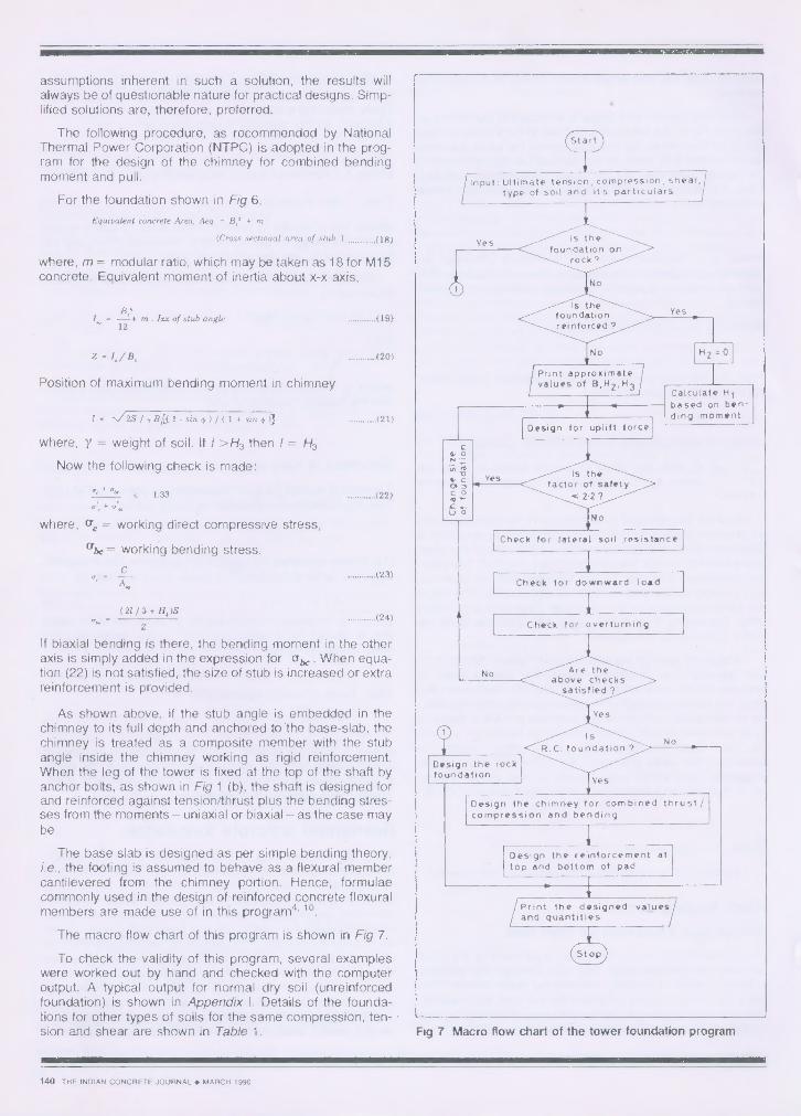
The macro flow chart of this program is shown in Fig 7.
To check the validity of this program, several exampleswere worked out by hand and checked with the computeroutput. A typical output for normal dry soil (unreinforcedfoundation) is shown in Appendix I. Details of the founda-tions for other types of soils for the same compression, ten-sion and shear are shown in Table 1.
=IP
Fig 7 Macro flow chart of the tower foundation program
(21)
(22)
(23)
(24)
140 THE INDIAN CONCRETE JOURNAL ♦ MARCH 1990
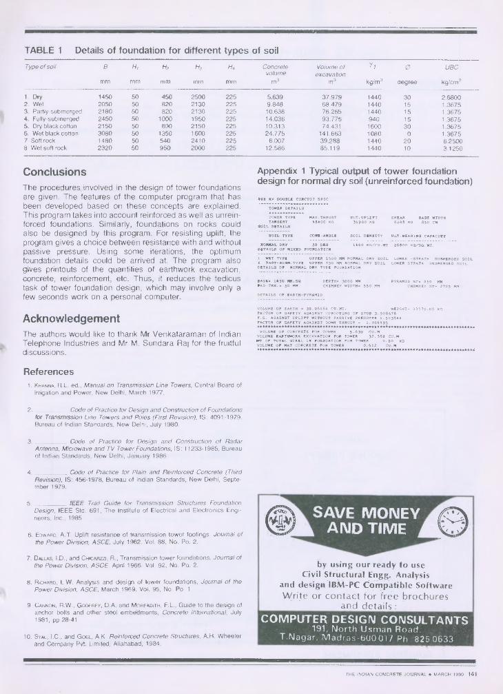
TABLE 1 Details of foundation for different types of soil
Type of soil B H, H2 H3 H,, Concrete Volume of yi 0 UBCvolume excavation
MM mm m m mm mm m3 m 3 kg/m3 degree kg/cm2
1. Dry 1450 50 450 2500 225 5.639 37.979 1440 30 2.68002. Wet 2050 50 820 2130 225 9.848 68.479 1440 15 1.36753. Partly-submerged 2180 50 820 2130 225 10.638 76.265 1440 15 1.36754. Fully-submerged 2450 50 1000 1950 225 14.036 93.775 940 15 1.36755. Dry black cotton 2150 50 800 2150 225 10.313 74.431 1600 30 1.36756. Wet black cotton 3080 50 1350 1600 225 24.775 141.663 1080 0 1.36757 Soft rock 1480 50 540 2410 225 6.007 39.288 1440 20 6.25008 Wet soft rock 2320 50 950 2000 225 12.586 85.119 1440 10 3.1250
4
ConclusionsThe procedures involved in the design of tower foundationsare given. The features of the computer program that hasbeen developed based on these concepts are explained.This program takes into account reinforced as well as unrein-forced foundations. Similarly, foundations on rocks couldalso be designed by this program. For resisting uplift, theprogram gives a choice between resistance with and withoutpassive pressure. Using some iterations, the optimumfoundation details could be arrived at. The program alsogives printouts of the quantities of earthwork excavation,concrete, reinforcement, etc. Thus, it reduces the tedicustask of tower foundation design, which may involve only afew seconds work on a personal computer.
AcknowledgementThe authors would like to thank Mr Venkataraman of IndianTelephone Industries and Mr M. Sundara Raj for the fruitfuldiscussions.
References1. KHANNA, R.L. ed., Manual on Transmission Line Towers, Central Board of
Irrigation and Power, New Delhi, March 1977.
2. Code of Practice for Design and Construction of Foundationsfor Transmission Line Towers and Poles (First Revision), IS: 4091 - 1979.Bureau of Indian Standards, New Delhi, July 1980.
3. Code of Practice for Design and Construction of RadarAntenna, Microwave and TV Tower Foundations, IS: 11233 - 1985, Bureauof Indian Standards, New Delhi, January 1986.
4. Code of Practice for Plain and Reinforced Concrete (ThirdRevision), IS: 456-1978, Bureau of Indian Standards, New Delhi, Septe-mber 1979.
5. . IEEE Trail Guide for Transmission Structures FoundationDesign, IEEE Std. 691, The Institute of Electrical and Electronics Engi-neers, Inc., 1985.
6. EDwARD. A.T. Uplift resistance of transmission tower footings, Journal ofthe Power Division, ASCE, July 1962. Vol. 88, No. Po. 2.
7. DALLAS, I.D., and CHICARZZI, R., Transmission tower foundations, Journal ofthe Power Division, ASCE, April 1966. Vol. 92, No. Po. 2.
8. RICHARD, L.W. Analysis and design of tower foundations, Journal of thePower Division, ASCE, March 1969. Vol. 95, No. Po. 1.
9 CANNON, R.W., GODFREY, D.A. and MOREADITH, F.L., Guide to the design ofanchor bolts and other steel embedments, Concrete International, July1981, pp 28-41.
10. SyAL, LC., and Goo_ A.K. Reinforced Concrete Structures, A.H. Wheelerand Company Pvt. Limited, Allahabad, 1984.
Appendix 1 Typical output of tower foundationdesign for normal dry soil (unreinforced foundation)
408 KV DOUBLE CIRCUIT SPIC
TOWER DETAILS
TOWER TYPE MAX.THRUST ULT.UPLIFT SHEAR EASE WIDTHTANGENT 48400 KG 31900 xo 6248 KO 85D CM
SOIL DETAILS
SOIL TYPE COOK-ANOLZ SOIL DENSITY ULT.EIZARING CAPACITY
NORMAL DRY 38 DIGDETAILS OF NIXIE. FOUNDATION
1 WWI TYPE UPPER 1500 MM NORMAL ORY SOIL LOWER -STRATA SUBMERGED SOIL• PART-SUBM.TYPZ UPPER 750 MN NORMAL DRY SOIL LOWER STRATA SUBMERGED SOILDETAILS OF NORMAL DRY TYPE FOUNDATION
BASE- 1450 MM.S0
DEPTH. 5000 MN PYRAMID HT. 450 MNPAD THK.. 50 PIM
CHIMNEY WIDTH. 550 MM CHIMNEY HT. 2725 MX
DETAILS OF 1ARTn-PYRAMID
VOLUME OF EARTH 38.96464 CU.ST. WEIGHT. 4 4 519,8 KGFACTOR OF SAFETY AGAINST UPROOTING OF STUB 3.508476F.S. AGAINST UPLIFT WITHOUT PASSIVE PRESSURE 1.503844FACTOR OF SAFETY AGAINST DOWN THRUST 1.004495
VOLUME OF CONCRETE FOR TOWER 5.639 CU.MVOLUM& EARTHWORK EXCAVATION FOR TOWER 37.362 CU.MMT OF TOTAL STEEL IN FOUNDATION FOR TOWER 0.80 KGVOLUME OF MAT CONCRETE FOR TOWER 0.612 CU.M
by using our ready to useCivil Structural Engg. Analysis
and design IBM-PC Compatible Software
Write or contact for free brochuresand details :
COMPUTER DESIGN CONSULTANTS191, North Usman Road,
T.Nagar, Madras-600 017 Ph:825 0633
1440 KO/CU.MT 26600 KG/SO.MT.
THE INDIAN CONCRETE JOURNAL ♦ MARCH 1990 141