cimple box assembly guide
TRANSCRIPT

1
www.andymark.com
CIMple Box
Assembly Guide
Version 1
Nov. 29, 2010

2
www.andymark.com
Contents Page
1. CIMple Box Overview and Specifications 2
2. CIMple Box Bill of Material and Part Photos 3
3. CIMple Box Assembly Instructions 5
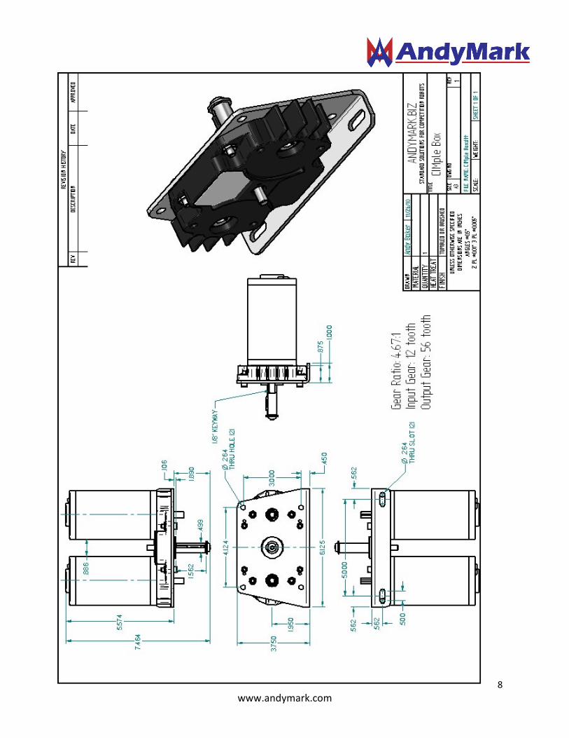
4. Layout Drawing 8
CIMple Box Overview and Specifications
The AndyMark CIMple Box gearbox (am-0734) is a single stage, spur gearbox. .
The CIMple Box is provided in kit form, unassembled. Full assembly instructions are included in this manual, and on the www.andymark.com website. Each CIMple Box includes all parts to mount two 2.5” CIM Motors as input devices. A US Digital E4P encoder fits onto the CIMple Box in between the two motor mount locations.
Gears:
• AGMA 620 dp, 14.5 deg. pressure angle
• Material: cold-formed 4140 steel
Gear Sizes:
� CIM Gear: 12 tooth (0.314” inside diameter with 2mm keyway) � Large Output Gear: 56 tooth (1/2” hex bore)
Gear Ratio:
• 4.67:1 (56/12)
Output Shaft:
• ½” diameter 4140 steel shaft, with 1/8” wide keyway
• ¼-20 x ½” deep threaded hole at end
• 1 machine key, washer and ¼-20 screw are provided
Materials:
• Housing: Nylon 6/6 with long fiber fill
• Shaft Plate: 5052 alumimum
• Gears: 4140 steel
3
www.andymark.com
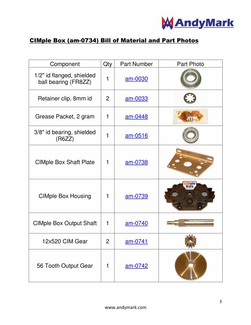
CIMple Box (am-0734) Bill of Material and Part Photos
Component Qty Part Number Part Photo
1/2" id flanged, shielded ball bearing (FR8ZZ)
1 am-0030
Retainer clip, 8mm id 2 am-0033
Grease Packet, 2 gram 1 am-0448
3/8" id bearing, shielded (R6ZZ)
1 am-0516
CIMple Box Shaft Plate 1 am-0738
CIMple Box Housing 1 am-0739
CIMple Box Output Shaft 1 am-0740
12x520 CIM Gear 2 am-0741
56 Tooth Output Gear 1 am-0742
4
www.andymark.com
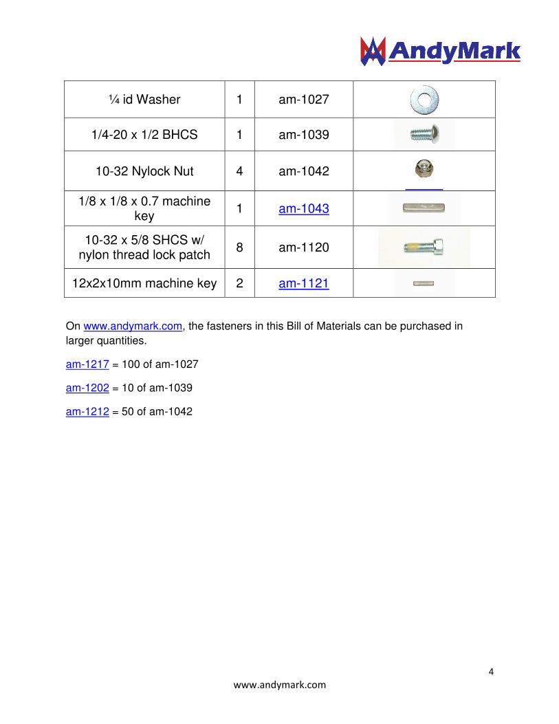
On www.andymark.com, the fasteners in this Bill of Materials can be purchased in
larger quantities.
am-1217 = 100 of am-1027
am-1202 = 10 of am-1039
am-1212 = 50 of am-1042
¼ id Washer 1 am-1027
1/4-20 x 1/2 BHCS 1 am-1039
10-32 Nylock Nut 4 am-1042
1/8 x 1/8 x 0.7 machine key
1 am-1043
10-32 x 5/8 SHCS w/ nylon thread lock patch
8 am-1120
12x2x10mm machine key 2 am-1121
5
www.andymark.com
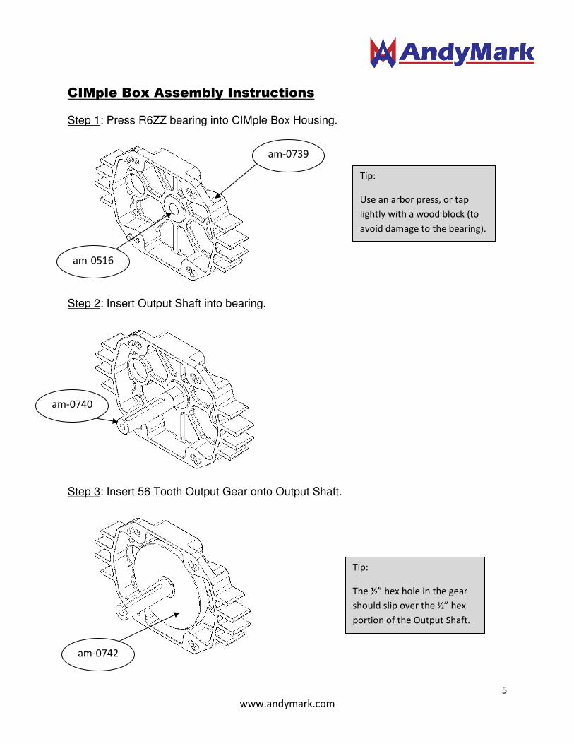
CIMple Box Assembly Instructions
Step 1: Press R6ZZ bearing into CIMple Box Housing.
Step 2: Insert Output Shaft into bearing.
Step 3: Insert 56 Tooth Output Gear onto Output Shaft.
Tip:
Use an arbor press, or tap
lightly with a wood block (to
avoid damage to the bearing).
Tip:
The ½” hex hole in the gear
should slip over the ½” hex
portion of the Output Shaft.
am-0739
am-0742
am-0516
am-0740

6
www.andymark.com
Step 4: Insert FR8ZZ Bearing into Shaft Plate.
Step 5: Slide the Shaft Plate and FR8ZZ Bearing onto the Output Shaft. This will be a tight slip fit. The four locating nubs on the Housing will line up with the four location holes on the Shaft Plate.
Step 6: One at a time, install 4 Nylock Nuts in the hex pockets on the back side of the Housing. Screw a 10-32 x 5/8” screw into each nut.
Tip:
Use an arbor press, or tap
lightly with a wood block (to
avoid damage to the bearing).
Tip:
Be sure that the FR8ZZ flange is
inside of the housing. If it is on
the outside of the plate, this
bearing will eventually fall out.
Tip:
You won’t need a wrench to
hold the nut. Just hold it into
the pocket with your finger as
you are driving the screw with
a 5/32” allen driver.
Location Holes
am-1120
am-1042
am-0738
am-0030
7
www.andymark.com
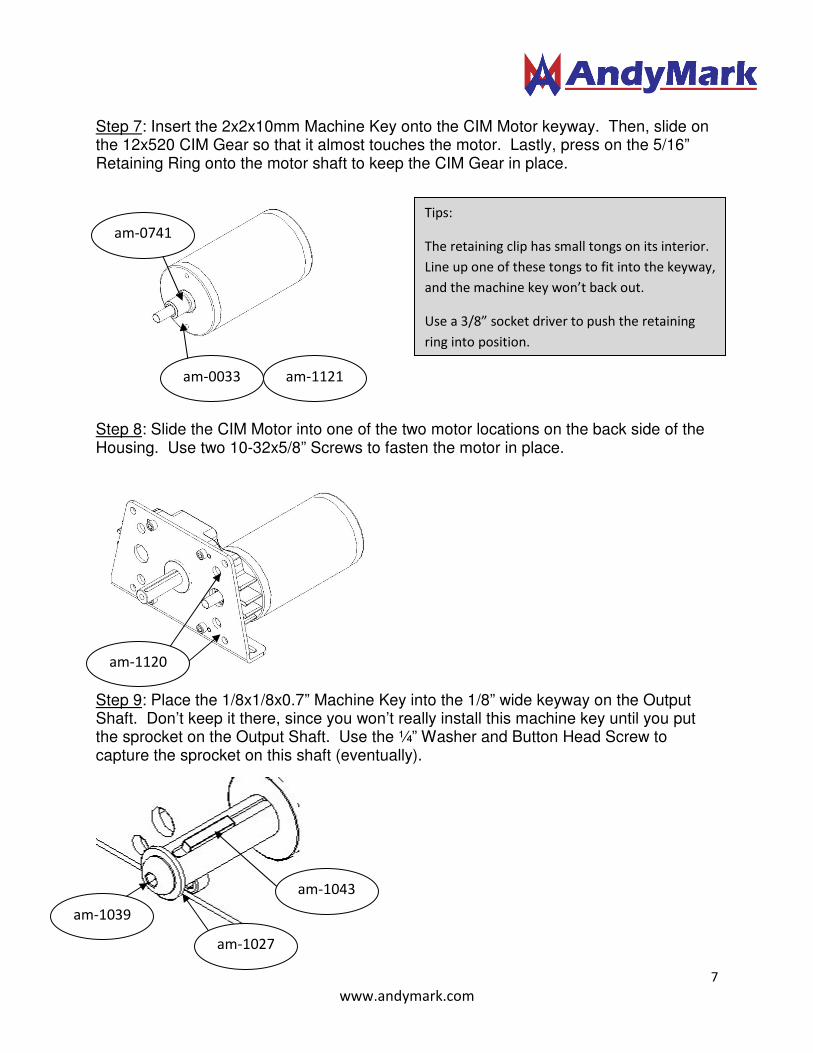
Step 7: Insert the 2x2x10mm Machine Key onto the CIM Motor keyway. Then, slide on the 12x520 CIM Gear so that it almost touches the motor. Lastly, press on the 5/16” Retaining Ring onto the motor shaft to keep the CIM Gear in place.
Step 8: Slide the CIM Motor into one of the two motor locations on the back side of the Housing. Use two 10-32x5/8” Screws to fasten the motor in place.
Step 9: Place the 1/8x1/8x0.7” Machine Key into the 1/8” wide keyway on the Output Shaft. Don’t keep it there, since you won’t really install this machine key until you put the sprocket on the Output Shaft. Use the ¼” Washer and Button Head Screw to capture the sprocket on this shaft (eventually).
Tips:
The retaining clip has small tongs on its interior.
Line up one of these tongs to fit into the keyway,
and the machine key won’t back out.
Use a 3/8” socket driver to push the retaining
ring into position.
am-0033
am-0741
am-1121
am-1120
am-1027
am-1043
am-1039
8
www.andymark.com