cipertm model 50 controller user guide
TRANSCRIPT

® U.S. Registered Trademark
Copyright © 2021 Honeywell Inc. • All Rights Reserved 31-00198-03
CIPerTM MODEL 50 CONTROLLER USER GUIDE
July 2021
IMPORTANT NOTE: Email your Host Id to Honeywell WEBs Customer Care ([email protected]), so that we can move the license to your organization. For additional queries contact your distributor.

CIPerTM MODEL 50 CONTROLLER – USER GUIDE
31-00198-03 2
Disclaimer The material in this document is for information purposes only. The content and the product described are
subject to change without notice. Honeywell makes no representations or warranties with respect to this
document. In no event shall Honeywell be liable for technical or editorial omissions or mistakes in this document,
nor shall it be liable for any damages, direct or incidental, arising out of or related to the use of this document. No
part of this document may be reproduced in any form or by any means without prior written permission from
Honeywell.
Copyright © 2021 HONEYWELL International, Inc. All rights reserved.
Software License Advisory
This document supports software that is proprietary to Honeywell Building Technologies and/or to third party
software vendors. Before software delivery, the end user must execute a software license agreement that governs
software use. Software license agreement provisions include limiting use of the software to equipment furnished,
limiting copying, preserving confidentiality, and prohibiting transfer to a third party. Disclosure, use, or
reproduction beyond that permitted in the license agreement is prohibited.
Trademark Notice
BACnet and ASHRAE are registered trademarks of American Society of Heating, Refrigerating and Air-
Conditioning Engineers. Microsoft, Excel, Internet Explorer, Windows, Windows Vista, Windows Server, and SQL
Server are registered trademarks of Microsoft Corporation. Oracle and Java are registered trademarks of Oracle
and/or its affiliates. Mozilla and Firefox are trademarks of the Mozilla Foundation. Echelon, LON, LonMark,
LonTalk, and LonWorks are registered trademarks of Echelon Corporation.
Niagara Framework ® is a registered trademark of Tridium Inc.
WEBs-AX, WEBs-N4 and WEBStation are registered trademarks of HONEYWELL International, Inc.
CIPerTM is registered trademark of Honeywell Building Technologies.

CIPerTM MODEL 50 CONTROLLER – USER GUIDE
3 31-00198-03
TABLE OF CONTENTS
Order numbers (SKU)............................................................................................................................................................... 5
HMI configuration principles ......................................................................................................................................................................6
HMI Service ..........................................................................................................................................................................................................7
HMI pin ...................................................................................................................................................................................................................9
HMI user rights ...................................................................................................................................................................................................9
HMI PIN lock-out...............................................................................................................................................................................................10
Enabling the alarming on the HMI ...........................................................................................................................................................11
Enabling the alarm LED on the HMI ........................................................................................................................................................11
Adjusting alarm poll-rate for the HMI .....................................................................................................................................................12
Local language HMI menus - translation .............................................................................................................................................13
Login user into the HMI and control the translation .......................................................................................................................13
Filling the Fast Access Lists .........................................................................................................................................................................14
Setting the time format on the home screen .......................................................................................................................................15
Onboard Inputs and Outputs ................................................................................................................................................ 16
Dual Ethernet ............................................................................................................................................................................. 17
Separated networks..........................................................................................................................................................................................17
Network switching mode ...........................................................................................................................................................................18
Combined network switching & separated networks ...................................................................................................................19
Front USB/Ethernet interface .....................................................................................................................................................................19
Secure Boot – Increased Cyber Security ................................................................................................................................................21
Part numbers and supporting material ..................................................................................................................................................22
Ordering Part Numbers ..............................................................................................................................................................................22
License Upgrades .........................................................................................................................................................................................22
Software Maintenance Agreements.........................................................................................................................................................22
Performance ........................................................................................................................................................................................................23
Performance tests ........................................................................................................................................................................................23
PanelBus Communication tuning .........................................................................................................................................................24
Panel-Bus cable type and length...........................................................................................................................................................25
I/O Modules .........................................................................................................................................................................................................26
Pluggable I/O Modules ..............................................................................................................................................................................26
Mixed I/O Modules.......................................................................................................................................................................................26
Terminal Sockets ...........................................................................................................................................................................................26
Color Coding ...................................................................................................................................................................................................26
LonWorks Product material number Substitution information ...............................................................................................28
Compatibility.............................................................................................................................................................................. 29
WEBs compatibility ..........................................................................................................................................................................................29
Input and Output module compatibility ................................................................................................................................................29
Spyder & Stryker tool compatibility...........................................................................................................................................................30
3rd party modules ...............................................................................................................................................................................................30
CIPer Model 50 modules ...............................................................................................................................................................................30
WEBs N4 Driver compatibility .....................................................................................................................................................................32
Web-Browser compatibility ..........................................................................................................................................................................33

CIPerTM MODEL 50 CONTROLLER – USER GUIDE
31-00198-03 4
CIPer Model 50 Firmware..............................................................................................................................................................................34
Firmware & Hardware compatibility .....................................................................................................................................................34
Firmware upgrade.........................................................................................................................................................................................34
Restore the CIPer Model 50 controller ...................................................................................................................................................35
Resetting CIPer Model 50 controller .......................................................................................................................................................37
Cable ...................................................................................................................................................................................................................37
Technical Documentation ............................................................................................................................................................................39
Appendix ..................................................................................................................................................................................... 40
USB Driver Installation for Windows 7 ....................................................................................................................................................40
USB Driver Installation for Windows 8 ....................................................................................................................................................43
USB Driver Installation for Windows 10 .................................................................................................................................................46

CIPerTM MODEL 50 CONTROLLER – USER GUIDE
5 31-00198-03
Order numbers (SKU)
The onboard HMI is featured in the below listed order numbers:
• WEB-EHSERIESNX26D
• WEB-EHSERIESNX26ND
IMPORTANT
To make efficient use of HMI functionality, it is required to do a few set-up steps in Honeywell
WEBStation N4.4.93 or higher. Refer to section HMI configuration principles given below.
WEB-EHSERIESNX26D
The XL2000HMI can be connected and operated with the below listed OS (SKU) numbers.
WEB-EHSERIESNX26ND

CIPerTM MODEL 50 CONTROLLER – USER GUIDE
31-00198-03 6
HMI configuration principles
To get the onboard HMI or detached HMI operational, the following configuration principles need to be done in
WEBs N4:
1. Add & enable the HMI Service.
2. Set a PIN for the HMI access.
3. Add HMI and LED Alarm recipients.
NOTE
As long as there are unacknowledged alarms in the station, the alarm symbol blink
regardless of the user is logged in to the HMI or not. See the picture below:
4. Configure the alarm for the HMI.
5. Fill the Fast Access Lists (FAL) with data points, schedules & parameters.
6. If desired, create a custom HMI sequence.

CIPerTM MODEL 50 CONTROLLER – USER GUIDE
7 31-00198-03
HMI Service
The onboard and detached HMI will only work when the HMI Service, called “HonEagleHawkHmiService” has been
placed into the “Services” of your station.
IMPORTANT
Always place the “HonEagleHawkHmiService” into the “Services” folder.
Do NOT place it under any service within “Services”
Steps to configure HMI Service
1. Select the “honEagleHawkHMI” palette and drag the “HonEagleHawkHmiService” into the “Services” of your station.
2. Enable the “HonEagleHawkHmiService”.
3. Changing, deleting, or translating the messages on the HMI.
4. Changing or deleting can be done in the property sheet of the HMI Service – see below:

CIPerTM MODEL 50 CONTROLLER – USER GUIDE
31-00198-03 8
For translating the “Warning” and “Welcome” message of the HMI, you can also use the WEBs N4 Lexicon tool,
see section “Local language HMI menus – translation” in this bulletin

CIPerTM MODEL 50 CONTROLLER – USER GUIDE
9 31-00198-03
HMI pin
PIN, PIN-configuration, and log-off definition are fully integrated with the Niagara “User Service”. This makes it
secure and allows to re-use the user definitions already in place for the station.
NOTE
It is mandatory to enter a 5-digit (Numeric only) PIN here. For security reasons, there is
no default PIN.
If the PIN is not present, the controller will not function.
HMI user rights
In the Admin column (marked red) for the user permissions of the RoleService, it is mandatory to enable “Read”
rights to the categories you want to access via HMI, otherwise, the user will have no access.
You may also provide the “Write” and “Invoke” rights to a category as required.

CIPerTM MODEL 50 CONTROLLER – USER GUIDE
31-00198-03 10
HMI PIN lock-out
For Cyber Security reasons, users will be locked out after multiple entries of a wrong PIN:
• After three wrong PIN entries in a row, user login is blocked for 1 min. For each wrong PIN after this, the user must wait for 1 min.
• This time sequence is repeated until a successful login is done.
NOTE
For Cyber Security reasons, all users are blocked during the waiting time.
This is intentional behavior.
1st time wrong PIN:
2nd time wrong PIN:
3rd time wrong PIN:
Wait time is 1 minute for all users.
4th / 5th / 6th / … etc time wrong PIN:
Correct PIN entry will restart the lock-out sequence.

CIPerTM MODEL 50 CONTROLLER – USER GUIDE
11 31-00198-03
Enabling the alarming on the HMI
From the “honEagleHawkHMI” palette, drag the “HmiAlarmConsoleRecipient” into the “Alarm Service” and
connect it to the “Default Alarm Class".
Enabling the alarm LED on the HMI
From the “clOnboardIO” palette, drag the “EagleHawkLedRecipient” into the “Alarm Service” and connect it to the
“Default Alarm Class”:

CIPerTM MODEL 50 CONTROLLER – USER GUIDE
31-00198-03 12
Adjusting alarm poll-rate for the HMI
The update rate for alarms and data points on the HMI has a default setting.
This can be adjusted with the CPU performance, to balance the information demand.
IMPORTANT
i). The faster the alarm and data-point poll rate, the more impact it will have on the
performance of the station. This might slower the CPU or station performance.
ii). The default setting for alarm and data-point poll-rate is 15s (15.000
milliseconds).
iii). The adjustable range is from 5s to 120s (5.000…120.000 milliseconds).
iv). By default, the poll-rate setting is hidden and can be made visible in the Slot
Sheet.
When adjusting for faster polling, watch the CPU load of the station.
To change the alarm poll rate
1. Select the alarm menu item and select the Slot Sheet:
2. Right-click the “updateIntervalMillis” and uncheck the “Hidden” flag.
3. Double-click the Alarm List in “HonEagleHawkHmiService” and change the poll rate as appropriate.

CIPerTM MODEL 50 CONTROLLER – USER GUIDE
13 31-00198-03
Local language HMI menus - translation
The HMI menus can be localized by making use of the standard Lexicon tool of WEBs N4:
• Open Lexicon tool of WEBs N4 and your local language lexicon file
• Open the “honEagleHawkHMI module
• Do the translations and save this lexicon file
• Commission the lexicon file into the controller
• Generate a new user which uses the new language file
Login user into the HMI and control the translation

CIPerTM MODEL 50 CONTROLLER – USER GUIDE
31-00198-03 14
Filling the Fast Access Lists
To fill the Fast Access Lists (FAL) with points, parameters, and schedules, you have two options:
• Option 1: Drag and drop points from the Navigation tree on the left into the Fast Access List on the property sheet on the right.
• Option 2: Use tagging: Drag and Drop “HonTagDictionary” into the “TagDictionaryService”. Select the point(s) you want to add, open the tag dialog, select the “HonTagDictionary” and select the tag “FALname”.
In the attached tag, add the name of the Fast Access List(s) you want to have this data point represented in. Separate multiple Fast Access Lists by using a semicolon “;”

CIPerTM MODEL 50 CONTROLLER – USER GUIDE
15 31-00198-03
Setting the time format on the home screen
1. Make sure that the Lexicon of the desired local language is installed. If not, use the Lexicon Installer to install it.
2. Set the language in the Station/PlatformService “locale” field.
CIPerTM MODEL 50 CONTROLLER – USER GUIDE
31-00198-03 16
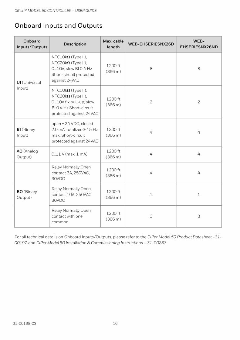
Onboard Inputs and Outputs
Onboard
Inputs/Outputs Description
Max. cable
length WEB-EHSERIESNX26D
WEB-
EHSERIESNX26ND
UI (Universal
Input)
NTC10kΩ (Type II),
NTC20kΩ (Type II),
0…10V, slow BI 0.4 Hz
Short-circuit protected
against 24VAC
1200 ft
(366 m) 8 8
NTC10kΩ (Type II),
NTC20kΩ (Type II),
0…10V fix pull-up, slow
BI 0.4 Hz Short-circuit
protected against 24VAC
1200 ft
(366 m) 2 2
BI (Binary
Input)
open = 24 VDC, closed
2.0 mA, totalizer @ 15 Hz
max. Short-circuit
protected against 24VAC
1200 ft
(366 m) 4 4
AO (Analog
Output) 0..11 V (max. 1 mA)
1200 ft
(366 m) 4 4
BO (Binary
Output)
Relay Normally Open
contact 3A, 250VAC,
30VDC
1200 ft
(366 m) 4 4
Relay Normally Open
contact 10A, 250VAC,
30VDC
1200 ft
(366 m) 1 1
Relay Normally Open
contact with one
common
1200 ft
(366 m) 3 3
For all technical details on Onboard Inputs/Outputs, please refer to the CIPer Model 50 Product Datasheet –31-
00197 and CIPer Model 50 Installation & Commissioning Instructions – 31-00233.

CIPerTM MODEL 50 CONTROLLER – USER GUIDE
17 31-00198-03
Dual Ethernet
The CIPer Model 50 is equipped with a Dual Ethernet interface. All information about the Dual Ethernet can be
found in the CIPer Model 50 Installation & Commissioning Instructions – 31-00233.
Separated networks
SEPARATED NETWORKS = DEFAULT SETTING
For cybersecurity reasons, the default setting of the Dual Ethernet is with the following IP settings:
• Ethernet port 1: IP address 192.168.200.20, subnet 255.255.255.0
• Ethernet port 2: IP address 192.168.201.20, subnet 255.255.255.0

CIPerTM MODEL 50 CONTROLLER – USER GUIDE
31-00198-03 18
Network switching mode
Optionally, the Dual Ethernet can be operated in network switching mode.
If this mode is desired, disable one of the Ethernet ports in WEBs N4 – see screenshot below.
Typical application scenarios are a closed BMS networks, like for daisy-chaining plant controllers or daisy-chaining room controllers on Ethernet.
NOTE
The switching functionality will not work during the power-fail of the CIPer Model 50 controller.
IMPORTANT
Set a gateway address
For the Ethernet switching functionality to work, it is mandatory to enter a Gateway address. If there is no gateway in the subnet, then use a gateway address that relates to the IP address of the Ethernet adapter that is enabled.
In the screenshot below, the gateway address is 192.168.1.1, hence the IP address of Ethernet adapter 1 must be
in the range of 192.168.1.2 to 192.168.1.255.

CIPerTM MODEL 50 CONTROLLER – USER GUIDE
19 31-00198-03
Combined network switching & separated networks
Optionally separating networks and switching functionality can be combined.
This allows to have one (or more) controllers connected to the customer intranet, and all other controllers residing
in a closed BMS network.
A typical application is the supervisory controller(s) accessible from the customer intranet, and the room
controllers residing in a closed network, and thus being not directly accessible from the customer intranet.
Front USB/Ethernet interface
All details regarding installation and commissioning of the CIPer Model 50 can be found within the Installation &
Commissioning Instructions – 31-00233.
All models of the CIPer Model 50 controller are equipped with a USB 2.0 Device interface at the front, which is an
Ethernet over the USB connection.
The permanent IP address of this USB interface is 192.168.255.241.
This interface allows connection of WEBs N4 for programming and operation, and web browsers or 3rd party touch
panels.
If your WEBs N4 PC or your web browser does not connect to this USB interface, the Windows driver may be
missing. In this case, please see Appendix chapters USB Driver Installation for Windows 7, USB Driver Installation
for Windows 8, and USB Driver Installation for Windows 10 installation for WINDOWS 7/8/10”.

CIPerTM MODEL 50 CONTROLLER – USER GUIDE
31-00198-03 20
ATTENTION:
Due to the risk of short-circuiting (see below figure), it is strongly recommended that the CIPer Model 50
controller be supplied with power from a dedicated transformer.
However, if the CIPer Model 50 controller is to be supplied by the same transformer powering other controllers or
devices (e.g., the PW M-Bus Adapter), care must be taken to ensure that correct polarity is observed.
For more details on the Power supply connections and recommended VA ratings, refer to the Power Supply
section in the CIPer Model 50 Installation & Commissioning Instructions – 31-00233.

CIPerTM MODEL 50 CONTROLLER – USER GUIDE
21 31-00198-03
Secure Boot – Increased Cyber Security
The CIPer Model 50 is an IIoT (Industrial Internet of Things) device.
Its benefits and typical deployments include network access as well as browser access via Intranet and Internet.
Beginning with the firmware of this release, the CIPer Model 50 will only boot and run authenticated WEBs N4
firmware. This is achieved by a firmware signature.
To achieve the best possible cybersecurity, please note the following:
1. Read and apply the Honeywell General Security Best Practices - 31-00129, available at the Honeywell Buildings Forum.
2. It is not possible to downgrade the released CIPer Model 50 firmware to a previous or older firmware version due to Cyber Security reasons.
3. Always install/upgrade to the latest firmware and software versions available on the Honeywell Buildings Forum for the latest secured versions and bug fixes.
4. Operate controllers either in internal networks, or use a coded VPN connection for internet access, to limit attacks from external Internet users.
5. Recommend your customers (network domain owners) to make use of HTTPS for secure web browser access to the controller.
6. Recommend your customers (network domain owners) to obtain a certificate from a Certification Authority and download this certificate into the controller.
7. If web access outside a VPN is to be realized, it should be handled through a firewall with appropriate “Whitelisting”, although a VPN is strongly recommended, because it is the best way to provide secure and encrypted communications to the controller.
8. Close all ports on the Internet router/gateway, and only open those ports that are mandatory for operation or maintenance, to minimize the attack surface.
9. BACnet (e.g. port 47808) should never be exposed to the Internet, not even through a firewall, but should only be exposed on internal networks or via a VPN because the BACnet protocol does not have security built-in.
10. Never use the default passwords, because they are widely available and are therefore easily guessed.
11. Use “strong” passwords, because modern password "crackers" can break simple passwords in a matter of minutes.
12. Never operate CIPer controllers unprotected on the open Internet.
NOTE
“Whitelisting” stands for allowing explicit IP-Addresses or MAC addresses of dedicated and trusted PCs
to access the controller behind the firewall and router.

CIPerTM MODEL 50 CONTROLLER – USER GUIDE
31-00198-03 22
Part numbers and supporting material
Ordering Part Numbers
Table 1. Ordering Part Numbers
OS Number (SKU) Description
WEB-EHSERIESNX26D CIPer Model 50 PLANT CONTROLLER, w/ HMI, 26 IO, 100 points, 5 devices
WEB-EHSERIESNX26ND CIPer Model 50 PLANT CONTROLLER, w/o HMI, 26 IO, 100 points, 5 devices
WEBSEHN4LIC CIPer MODEL 50 CORE LICENSE with SMA-0005-1YR-INT
PIN-0005 - 18 mo Maintenance
License Upgrades
Table 2. License Upgrades
Model License content/Upgrade license
EAGLEH255PUP 255 Additional Panel-bus Expansion I/O Points
PIN-DEV-UP-1 +50 open points upgrade, +1 Device
PIN-DEV-UP-2 +100 open points, +2 Devices
PIN-DEV-UP-10 +500 open points, +10 Devices
PIN-DEV-UP-25 +1250 open points, +25 Devices
PIN-DEV-UP-50 +2500 open points, +50 Devices
Software Maintenance Agreements
Table 21. Software Maintenance Agreements
Model License content/Upgrade license
SMA-0005-1YR PIN-0005 - 1 year maintenance
*SMA-0005-1YR-INIT PIN-0005 - Initial 18 month maintenance must be purchased in conjunction with the initial Core software. Optional 3 or 5 year maintenance may be substituted.
SMA-0005-3YR PIN-0005 - 3 year maintenance
SMA-0005-5YR PIN-0005 - 5 year maintenance
SMA-0010-1YR PIN-0010 - 1 year maintenance
SMA-0010-1YR-INIT PIN-0010 - Initial 18 month maintenance must be purchased in conjunction with the initial Core software. Optional 3 or 5 year maintenance may be substituted.
SMA-0010-3YR PIN-0010 - 3 year maintenance
SMA-0010-5YR PIN-0010 - 5 year maintenance
SMA-0025-1YR PIN-0025 - 1 year maintenance
SMA-0025-1YR-INIT PIN-0025 - Initial 18 month maintenance must be purchased in conjunction with the initial Core software. Optional 3 or 5 year maintenance may be substituted.
SMA-0025-3YR PIN-0025 - 3 year maintenance
SMA-0025-5YR PIN-0025 - 5 year maintenance
SMA-0100-1YR PIN-0100 - 1 year maintenance
SMA-0100-1YR-INIT PIN-0100 - Initial 18 month maintenance must be purchased in conjunction with the initial Core software. Optional 3 or 5 year maintenance may be substituted.
SMA-0100-3YR PIN-0100 - 3 year maintenance
SMA-0100-5YR PIN-0100 - 5 year maintenance
NOTE : *included with the initial purchase of WEBSEHN4LIC

CIPerTM MODEL 50 CONTROLLER – USER GUIDE
23 31-00198-03
Performance
Performance tests
The system boundaries are hard to define, as they depend on many factors, such the boundaries of the hardware
performance in general, the network performance, the “traffic” created by the application, concurrent polls from
Supervisors, Station Save intervals, Recovery Service intervals, etc.
In addition to the general Tridium guidance of a maximum of 80% CPU load, Honeywell has undertaken two
exemplary performance tests.
The maximum recommended CPU usage is outlined in the two tables below.
No. of
modules
No. of
hardware
I/O points
Points
in PX
pages
Freq. of
value
changes
Histories
enabled CPU usage Test result
Panel Bus (via
RS485-1) 46 A) 491 491B)
2 sec
(poll rate) --
30%
(occasionally:
50%)
OK for non-
critical
applications
C) BACnet MS/TP
(via RS485-2) 13 559 559 D)
2 sec
(COV) E) 500
A) 9x 821A, 9x 822A, 9x 823A, 9x 824, 5x 825, 5x 830A
B) Four (4) PX pages: AI, AO, BI, and BO points each in a dedicated PX page per point type
C) About 0.5% of the BACnet MS/TP point updates are occasionally delayed.
D) One (1) PX page with all points
E) COV: Change of Value. COV frequency is the rate of change in the value of an object property.
COV E)
frequency
Max. no. of COV updates per min.
across RS485-1 and RS485-2
together
CPU usage test result
BACnet MS/TP at
38,500 bps 4 sec 4,000
25…35%
(occasionally:
60%)
OK

CIPerTM MODEL 50 CONTROLLER – USER GUIDE
31-00198-03 24
PanelBus Communication tuning
The default polling time for all Panel-Bus points is set to “Normal = 10s”.
This means that the data from the field are updated every 10s.
Write commands are sent without time delay.
The polling frequency can be changed, and we do recommend that it must be updated more frequently.
IMPORTANT
For CIPer Model 50, the fastest poll rate is 200 milliseconds.
Do NOT set a faster poll rate, as this may overload the CPU in larger systems.
Editing the standard polling frequency can be done inside the “Poll Scheduler” of the Property Sheet of the
PanelbusNetwork:
WEBRS485-1

CIPerTM MODEL 50 CONTROLLER – USER GUIDE
25 31-00198-03
The Assignment of the different Poll Intervals for each point is done inside the Panelbus Point Discovery Dialog.
Panel-Bus cable type and length
See CIPer Model 50 Installation and Commissioning Instructions – 31- 00233 for all details.
Max. Panel Bus length:
120 ft (36.5 m) for any type of cabling and topology. No additional end termination is permitted.
2400 ft (731.5m) for twisted-pair or telephone cable and daisy chain topology. The Controller must be positioned
at one end of the Panel-Bus, and an end termination (120 Ω) at the other end. Furthermore, the three-position
slide switch must be set to "END." Use Honeywell cable 3322 or 3251.

CIPerTM MODEL 50 CONTROLLER – USER GUIDE
31-00198-03 26
I/O Modules
Pluggable I/O Modules
There are 2 variants of pluggable I/O modules:
• Panel Bus I/O modules with communication via Panel Bus (light-gray housings). Panel Bus I/O modules are automatically commissioned (with firmware download) by the CIPer Model 50 Controller.
• LONWORKS Bus I/O modules (dark-gray housings) with communication via LONWORKS (FTT10-A, link power compatible) for easy integration and use with 3rd-party controllers.
Mixed I/O Modules
Besides the pluggable Panel Bus I/O modules (consisting of a terminal socket and a removable electronic
module), there are also mixed Panel Bus I/O modules. Specifically: the XFU830A is mixed Panel Bus I/O module,
featuring an integrated screw terminal (incl. bridge connector and swivel label) and a variety of inputs and
outputs; housing matches XL800 design. Mixed Panel Bus I/O modules have a light-gray housing and are
likewise automatically commissioned (with firmware download) by the CIPer Model 50 Controller.
Terminal Sockets
Pluggable I/O modules must be mounted on the appropriate terminal sockets. Pluggable Panel Bus I/O modules
and pluggable LONWORKS Bus I/O modules use the same terminal sockets. These terminal sockets are available
with a screw-type terminal (XSU82…).
Mixed I/O modules feature an integrated terminal socket. 128 Panel-Bus IO modules per CIPer Model 50 are
supported.
Color Coding
To distinguish modules and components, the following color coding is used:
Color Part
Red All of the user-accessible adjustable mechanical parts (i.e., bridge connectors and locking
mechanism) and operating controls (manual overrides, etc.)
Light-gray Panel Bus I/O modules
Dark-gray LONWORKS Bus I/O modules

CIPerTM MODEL 50 CONTROLLER – USER GUIDE
27 31-00198-03
Pluggable
Analog Input
Pluggable
Analog Output
Pluggable
Binary Input
Pluggable Relay
Output
Pluggable
Floating
Output
Mixed I/O
LonWorks
BUS
MODULE
PANEL
BUS
MODULE
XFR825A
LonWorks or Panel Bus
CIPer Model 50
XFU830A

CIPerTM MODEL 50 CONTROLLER – USER GUIDE
31-00198-03 28
Panel Bus I/O Module Overview
Panel Bus module
LonWorks
Bus module
Description Inputs Outputs Manual controls
LEDs A)
XF821A *XFL821A Analog input module
8 – – –
XF822A *XFL822A Analog output module
– 8 – 8 status LEDs
XFR822A *XFLR822A Analog output module
– 8 8 Manual overrides
8 status LEDs
XF823A *XFL823A Binary input module
12 – – 12 status LEDs
XF824A *XFL824A Relay output module
– 6 B) – 6 status LEDs
XFR824A *XFLR824A Relay output module
– 6 B) 6 Manual overrides
6 status LEDs
XFR825A – Floating output module
– 3 3 Manual overrides
3 pairs of status LEDs
XFU830A - Mixed I/O Module 8 AI
12 BI
8 AO
6 BO
A) In addition to the power LED and service LED B) Changeover outputs
* Module no longer supportable, refer substitute product option(s)
IMPORTANT
LonWorks Product material number Substitution information
LonWorks Bus module products are no longer supportable. Substitute product option(s) have been identified to help ease the transition to currently supported products.
Please refer to the below table for Replacement.
Material Description Replacement
XFL821A 8 ANALOG INPUT (LON)
1. IF-LON2 w/ CIPer 50 & panelbus I/O
2. CLIF-CBUS
3. LON Spyder
4. LON Stryker
XFL822A 8 ANALOG OUPUT MODULE (LON)
XFL823A 12 BINARY INPUT MODULE (LON)
XFL824A 6 RELAY OUTPUT MODULE (LON)
XFLR822A 8 ANALOG OUTPUT MODULE (LON) W/OVR
XFLR824A 6 RELAY OUTPUT MODULE (LON) W/OVR
NOTE: If you do not purchase products directly from Honeywell, please coordinate purchases of the ‘End of Life’ products with your current supplier. In this case, recognize that your supplier must meet the outlined ‘Last Time Buy’ parameters. If you have any questions concerning this ‘End of Life’ or ‘Last Time Buy’ process, please contact your Distributor or Honeywell Sales Representative.

CIPerTM MODEL 50 CONTROLLER – USER GUIDE
29 31-00198-03
Compatibility
WEBs compatibility
WEBs 4.4U2 or higher is mandatory for CIPer Model 50, also the related jar files and modules to run the CIPer
Model 50 with HMI. Downloaded the workbench version WEBs N4.4.93 or higher from the Honeywell Buildings
Forum.
For compatibility of WEBs N4, please refer to the latest Release Bulletin.
Input and Output module compatibility
All Panel-Bus module versions (XF8xxx…) are supported by CIPer Model 50.
• XF821A
• XF822A, XFR822A
• XF823A
• XF824A, XFR824A
• XFR825A
• XFU830A
All LON I/O modules (XFL8xxx) are supported by CIPer Model 50.
Please review license limitations if LON modules should be used.
• *XFl821A
• *XFL822A, *XFLR822A
• *XFL823A
• *XFL824A, *XFLR824A
Note: *For replacement, refer to LonWorks Product material number Substitution information.

CIPerTM MODEL 50 CONTROLLER – USER GUIDE
31-00198-03 30
Spyder & Stryker tool compatibility
The Spyder tool is supported by CIPer Model 50 controller. Configured Spyder controllers LON and/or BACnet can
be integrated. They are supported as 3rd party LON and BACnet devices. The CIPer Model 50 comes with a
Honeywell license with the features required to program a non-ILC Spyder.
3rd party modules
Support and distribution of WEBs N4 modules that have been developed and distributed by 3rd party companies
lie with these 3rd party companies.
CIPer Model 50 modules
The following are the modules supported by CIPer Model 50 controller:
NOTE
These modules are supported by CIPer Model 50 controller, from WEBs N4.4.93 or higher versions.
Module Description Version
CentralineAhuPx-wb Centraline AHU Graphics 4.3.58.24.1
CentralineHtgPx-wb Centraline Heating Plant Graphics 4.3.58.24.1
CentralineLONIOr5-wb LON IO and Smart IO 4.10.0.2.0.12
clEnoceanNetwork-rt Enocean Network Utilities 4.3.58.1.84
clEnoceanNetwork-wb Enocean Network Utilities 4.3.58.1.84
clHVACAirConditioning-doc HVAC control macro library: Air Conditioning
4.8.0.110.51 clHVACAirConditioning-rt
clHVACChiller-doc HVAC control macro library: Chiller 4.8.0.110.51
clHVACChiller-rt
clHVAC-doc Eagle control primitives 4.4.94.14.1.10
clHVACEnergyManagement-doc HVAC control macro library: Energy
Management 4.8.0.110.51
clHVACEnergyManagement-rt
clHVACGeneral-doc HVAC control macro library: General 4.8.0.110.51
clHVACGeneral-rt
clHVACHeating-doc HVAC control macro library: Heating 4.8.0.110.51
clHVACHeating-rt
clHVACNordicAirCondition-doc HVAC control macro library: Nordic Air
Conditioning 4.8.0.110.51
clHVACNordicAirCondition-rt
clHVACNordicGeneral-doc HVAC control macro library: Nordic General
4.8.0.110.51 clHVACNordicGeneral-rt
clHVACRoomControl-doc HVAC control macro library: Room Control
4.8.0.110.51 clHVACRoomControl-rt
clHVAC-rt Eagle control primitives 4.4.94.14.1.10
clHVAC-wb
clIOcreation-rt Honeywell IO Creation modules 4.10.0.2.0.12

CIPerTM MODEL 50 CONTROLLER – USER GUIDE
31 31-00198-03
Module Description Version
clIOcreation-wb
clOnboardIO-rt Honeywell Onboard-IO Driver 4.10.0.2.0.12
clOnboardIO-wb
clPanelBus-rt Honeywell Panelbus serial driver 4.10.0.2.0.12
clPanelBus-wb
clPrintout-doc
Honeywell Printout 4.10.0.2.0.12 clPrintout-rt
clPrintout-wb
honEagleHawkHMI-rt Honeywell Human Machine Interface
4.10.0.2.0.12 honEagleHawkHMI-ux
honEagleHawkHMI-wb
honTagDictionary-rt Honeywell Tag Dictionary to generate station model based on HBT Ontology
4.10.0.2.0.12
platPanelbus-rt Honeywell Panelbus Platform Service 4.10.0.2.0.12
Steps to install into WEBs N4
1. Shut-down CIPer Model 50 controller.
2. Copy the *.jar files into the folder “c:\Honeywell\WEBStation-N4-4.x.x.xx\modules\” on your PC where the WEBStation N4 installation resides.
3. Restart WEBStation N4 workbench.
NOTE
While booting the controller station, a warning displays in the application directory.
This is a default behavior; it will not impact the controller's functionality or
performance.
4. Run the “software manager” and “update all out-of-date” files.
5. Start station.

CIPerTM MODEL 50 CONTROLLER – USER GUIDE
31-00198-03 32
WEBs N4 Driver compatibility
Supported Drivers
Protocol Default Port Hardware Interface(s)
Platform Daemon 3011 Ethernet RJ45, IP via USB-B
Platform Daemon SSL 5011 Ethernet RJ45, IP via USB-B
Station (FOX) 1911 Ethernet RJ45, IP via USB-B
Station Secure (FOXS) 4911 Ethernet RJ45, IP via USB-B
HTTP * 8080
8443
Ethernet RJ45, IP via USB-B
BACnet/IP 47808 Ethernet RJ45
Email, SMTP 25, 465, 587 (check Email provider) Ethernet RJ45
TCP/IP N/A Ethernet RJ45, IP via USB-B
SSH N/A Not supported
SNMP 10161, 10162 Ethernet RJ45
MQTT 1883 Ethernet RJ45
MQTT Secure 8883 Ethernet RJ45
KNX EIBnet/IP 3671 Ethernet RJ45
LON IP 2540, 2541 Ethernet RJ45
Modbus TCP 502 Ethernet RJ45
oBIX 80 or 8443 Ethernet RJ45
Open ADR Check customer System Admin
(e.g. 80, 8443, 5222, 5223, 5269,
5280)
Ethernet RJ45
EnOcean Check customer System Admin Ethernet RJ45
Fidelio FIAS MICROS
protocol
Check customer System Admin Ethernet RJ45
C-Bus Driver (SUSI) 2499 Ethernet RJ45
BACnet MSTP N/A RS485-1, RS485-2
Panel-Bus N/A RS485-1, RS485-2
Modbus RTU/ASCII
Master
N/A RS485-1, RS485-2
Modbus RTU/ASCII
Slave
N/A RS485-1, RS485-2
M-Bus N/A RS232 plus PW3/20/60
NOTE
For Cyber Security reasons, all ports ranging 1024 or lower cannot be used for services on the device.

CIPerTM MODEL 50 CONTROLLER – USER GUIDE
33 31-00198-03
Information on HTTP and HTTPS ports:
WEBs-N4 Version N4.4.93 or higher includes a template which automatically changes these two ports to 8080
(HTTP) and 8443 (HTTPS), when creating a new station.
Un-supported Drivers
Protocol Hardware Interface(s)
CCTV
Not supported for performance reasons.
Ethernet RJ45
SMS
The Niagara framework does not support this protocol on N4.
RS232 plus modem
RdbmsNetwork Ethernet RJ45
Drivers not tested
Protocol Hardware Interface(s)
Other drivers listed under “Supported Drivers” and “Un-supported Drivers” may
well work but have not been tested.
Ethernet RJ45
Web-Browser compatibility
Supported browsers are Google Chrome, Mozilla Firefox, MS Internet Explorer 11, and MS Edge.
For the best result, we recommend the current version of Google Chrome.

CIPerTM MODEL 50 CONTROLLER – USER GUIDE
31-00198-03 34
CIPer Model 50 Firmware
Firmware & Hardware compatibility
This WEBs N4 firmware version is compatible with all released CIPer Model 50 models, date code 1844 or later,
see table below:
OS Number (SKU) Description Built-in IO
points
WEB-EHSERIESNX26D CIPer Model 50 PLANT CONTROLLER, w/o HMI, 26 IO, 100 points, 5 devices
26 WEB-EHSERIESNX26ND
CIPer Model 50 PLANT CONTROLLER, w/o HMI, 26 IO, 100 points, 5 devices
WEBSEHN4LIC CIPer Model 50 Core License with SMA-0005-1YR-INT
PIN-0005 - 18 mo Maintenance
Firmware upgrade
Check the installed firmware version in your CIPer Model 50.
Open WEBs N4, go to the Platform/Platform Administration, and check the version of the Niagara Runtime for the
CIPer Model 50 installed.
Firmware updates may be available on the Honeywell Buildings Forum and the firmware upgrade procedure will
be available with the firmware updates. If there are any queries on Firmware updates, please reach out to your
WEBs technical support.

CIPerTM MODEL 50 CONTROLLER – USER GUIDE
35 31-00198-03
Restore the CIPer Model 50 controller
The CIPer Model 50 restore functionality has been enhanced to offer three levels of delete and restore, with three
different CleanDist files.
These CleanDist files allow each user to individually clean up the respective CIPer Model 50 controller according
to the requirements. To restore the CIPer Model 50 user needs to install the "Clean Dist" file.
NOTE
If there are any unsigned third-party modules with a release level of N4.10 or below connected to your
system, then any attempt to upgrade your controller may fail. For a successful controller upgrade, make
sure to sign all third-party modules using Niagara’s Jar Signing Tool.
If the upgrade still not successful after signing the third-party modules, then you should perform the
factory reset using the clean-dist-honeywell-nxubc.dist file.
Choose one of the following "CleanDist" files to delete and restore settings on the CIPer Model 50 controller.
CleanDist Files Details
CleanDist Type CleanDist file Version Description
CleanDist 1 clean-dist-1-
honeywell-nxubc.dist
1.2 Deletes all the station and modules.
CleanDist 2
clean-dist-2-
honeywell-nxubc.dist
1.4 Deletes all the station, modules, system passphrase,
username and password, and clean-up service folder
CleanDist 3
(Restore CIPer
50 Controller to
factory out
settings.)
clean-dist-3-
honeywell-nxubc.dist
1.3 Deletes all the station, modules, system passphrase,
username and password, clean-up service folder, license,
and certificates. Also resets the IP address to its default i.e.
• Ethernet interface 1: 192.168.200.20, mask
255.255.255.0
• Ethernet interface 2: 192.168.201.20, mask
255.255.255.0
Additionally, CleanDist 3 will reset the installed firmware to
the Factory Firmware Version 4.4.92.2.1.04.3.
Which Elements are deleted? CleanDist 1 CleanDist 2 CleanDist 3
Station X X X
Module X X X
System Passphrase -- X X
User & Password -- X X
Cleanup Service Folder -- X X
IPAddress -- -- X
License and Certificates -- -- X
Firmware -- -- X
Factory Default

CIPerTM MODEL 50 CONTROLLER – USER GUIDE
31-00198-03 36
NOTE
Factory out CIPer Model 50 Controller
The Factory out CIPer Model 50 Controller comes with WEBs N4.4 versions, which prevents the version
conflict during commissioning between engineering tool and controller.
The introduction of this basic firmware became necessary because the CIPer Model 50 controller cannot
downgraded in terms of the firmware. The base firmware does not allow to start a station and therefore it
must be upgraded to the appropriate firmware version using the Commissioning Wizard.
Before performing CIPer 50 controller rstoring process, make sure to copy clean dist file in the
C:\Honeywell\WEBStation-N4-4.x.x.xxx\cleanDist folder.
Steps to restore CIPer Model 50 Controller:
1. Connect and enter login details of the CIPer Model 50 platform.
NOTE
Users must keep a record of login credentials details for the CIPer Model 50 platform.
2. Select Distribution File Installer.
3. Select the file clean-dist-1-honeywell-nxubc.dist from the list and click the Install
.
Wait for the installation to complete.
After the installation has been completed, the CIPer Model 50 controller will disconnect and reboot.
o The default platform passphrase will be active after reboot, enter default login/password for the platform will be active after a reboot. After entering logging credentials Licenses and Certificates and TCP IP Address Settings will retain.
o This action will delete all the modules, station and station data will be erased.
o Now the Firmware is retained.
4. Click Close after completing the installation.

CIPerTM MODEL 50 CONTROLLER – USER GUIDE
37 31-00198-03
Resetting CIPer Model 50 controller
To reset the CIPer Model 50 controller, the user needs to delete the following
• Passphrase
• Username
• Password
• Ethernet IP
• Station
NOTE
In order to delete Modules, the “Clean dist file” needs to be downloaded.
Cable
Using the following two cables connected end-to-end, TECHTOO USB 3.0 and YIOVVOM DB9 Breakout
Connector, setup a connection between the CIPer Model 50 and a terminal program (Putty) via RS232.
Therefore you need the cables TECHTOO USB 3.0 and YIOVVOM DB9 Breakout Connector. Both a USB RS-232
DB-9 male adapter (since most PCs and laptops no longer have a conventional DB-9 male jack) as well as a nifty
little DB-9 female Jack with (small) screw terminals to connect wires (your cut Ethernet cable) to the pins.
To can make up your RJ-45 to conventional to RS-232 DB-9 female connecting cable using a standard Ethernet
cable with the one end cut off. The standard color codes are:
Pin 2 / RxD (receive data) = Orange
Pin 3 / TxD (transmit data) = White/Green stripe
Pin 5 / GND = White/Blue Stripe
For proper serial communication:
Tx on your host (laptop) must go to Rx on the CIPer50
Tx on the CIPer50 must connect to Rx on your host so
your Wire PIN 2 <> PIN 3 and PIN 3 <> PIN 2.
At the RS-232 DB-9 female connection:
• Orange > DB-9 pin 3
• White/Green > DB-9 Pin 2
• White/Blue > DB-9 Pin 5
You can purchase an equivalent cable or make one yourself as well.

CIPerTM MODEL 50 CONTROLLER – USER GUIDE
31-00198-03 38
NOTE
TECHTOO USB 3.0 to Serial Adapter USB RS232 Cable USB Serial
Cable Converter DB9 USB (10ft) with FTDI Chipset Gold Plated for
Win10/8.1/8/7/Vista/XP/2000/Android/Linux/Mac OS X10.6 &
Above.
YIOVVOM DB9 Breakout Connector to Wiring Terminal RS232 D-
SUB Male Serial Adapters Port Breakout Board Solder-Free Module
with case (Female Serial Adapter).
Connect the RS232 of the CIPer Model 50 (red marked) with the com port of your PC.
1. Start your terminal program and setup the serial interface with the following settings.
2. After the terminal program has started you have to restart the CIPer Model 50.

CIPerTM MODEL 50 CONTROLLER – USER GUIDE
39 31-00198-03
3. When the following screen is shown in the terminal program you have 3 seconds to push the key “c” to start the Boot menu.
4. The Boot menu looks like the below image.
5. Now push "F" to choose the reset the controller to factory default menu point.
6. To start the reset procedure, press the key “Y”.
7. Now the IP-Address and Login credential will also so be reset to default in addition to the modules and station.
Default platform Credentials:
• Passphrase = niagara
• Username = tridium
• Password = tridum
The default primary interface IP address is 192.168.200.20 and the subnet mask is 255.255.255.0
Technical Documentation
Product Document type Document name
WEBs Honeywell General Security Best Practices 31-00129
CIPer Model 50 Product Data Sheet 31-00197
CIPer Model 50 Mounting Instructions 31-00234
CIPer Model 50 Installation and Commissioning Instructions 31-00233
CIPer Model 50 Sell sheet 01-00110

CIPerTM MODEL 50 CONTROLLER – USER GUIDE
31-00198-03 40
Appendix
USB Driver Installation for Windows 7
1. Insert the A Male connector of the USB cable into an USB interface jack of the PC and insert the B Male connector into the controller´s USB device interface jack.
RESULT: The Found New Hardware Wizard is enabled in the Windows Task Line.
2. In the Windows Task Line, double-click the icon.
RESULT: The Driver Software Installation message box displays.
3. If no RNDIS/Ethernet Gadget driver was found as indicated by the message ´X No driver found`, click the Change setting… button.
RESULT: The Device Installation Settings dialog box displays.
4. Select No, let me choose what to do, and then select Install driver software from Windows Update if it is not found on my computer.
5. Click the Save Changes button.
RESULT: Software tries to install the RNDIS/Ethernet Gadget driver. If the driver is successfully installed, it can be seen in the following locations within Windows (see figures below):
6. In Control Panel\Hardware and Sound \ Devices and Printers.

CIPerTM MODEL 50 CONTROLLER – USER GUIDE
41 31-00198-03
In Control Panel \ Network and Internet \ Network Connections.
In Control Panel \ Device Manager \ Network Adapters
If the driver has still not been successfully installed, do the following:
7. Right-click on the driver in the Network adapters folder in the Device Manager, and then click Update Driver Software.
8. Click Browse my computer for driver software.
9. Click Let Me Pick from a list of device drivers on my computer.
10. Click Have Disk.
11. Click Browse and navigate to the folder <drive:>\CARE\drivers.
12. Depending on your Windows operating system type (32 bit or 64 bit), select the RNDIS USB driver (32Bit) or the RNDIS USB driver (64Bit) file, and then click Open.

CIPerTM MODEL 50 CONTROLLER – USER GUIDE
31-00198-03 42
13. Click OK.
14. Select Linux USB Ethernet/RNDIS Gadget, and then click Next>.
15. If a warning message displays, click Continue Anyway.
RESULT: Windows will install the driver.
16. Click Close.
17. Check the successful installation of the driver as described in step 5.
18. If this still does not work, use the driver shipped with Windows.
19. Right-click on the driver in the Network adapters folder in the Device Manager, and then click Update Driver Software.
20. Click Browse my computer for driver software.
21. Click Let Me Pick from a list of device drivers on my computer.
22. Uncheck the Show compatible hardware box.
23. Select the Manufacturer Microsoft Corporation.
24. Select Remote NDIS Compatible Device.
25. Check the successful installation of the driver as described in step 5.
26. If the device status is “This device cannot start. (Code 10)”, reboot your PC.

CIPerTM MODEL 50 CONTROLLER – USER GUIDE
43 31-00198-03
USB Driver Installation for Windows 8
1. Insert the A Male connector of the USB cable into a USB interface jack of the PC and insert the B Male connector into the controller´s USB device interface jack.
2. In Windows, start the device manager.
3. Click Other devices, then right-click RNDIS/Ethernet Gadget, and then select Update Driver Software.
RESULT: The Update Driver Software – RNDIS/Ethernet Gadget dialog displays.
4. Click Browse my computer for driver Software.

CIPerTM MODEL 50 CONTROLLER – USER GUIDE
31-00198-03 44
5. Click Let me pick from a list of device drivers on my computer.
6. Select Network adapters.

CIPerTM MODEL 50 CONTROLLER – USER GUIDE
45 31-00198-03
7. Select Microsoft.
8. Select USB-RNDIS-Adapter, and then click Next button.
RESULT: The Update Driver Warning message box displays.

CIPerTM MODEL 50 CONTROLLER – USER GUIDE
Honeywell Building Technologies
1985 Douglas Drive North
Golden Valley, MN 55422
customer.honeywell.com
Honeywell Building Controls
® U.S. Registered Trademark © 2020 Honeywell International Inc. 31-00198-03 | Rev 07-2021
9. Confirm the warning by clicking Yes button.
RESULT: The driver will be installed successfully as indicated by the final message box.
10. Click the Close button.
USB Driver Installation for Windows 10
Typically, the appropriate driver is automatically installed with a Windows update.
If you have issues with the installation, please contact the manufacturer of your PC to obtain updates on the
chipset driver.