circuit board lab pov business card
TRANSCRIPT
8/13/2019 Circuit Board Lab POV Business Card
http://slidepdf.com/reader/full/circuit-board-lab-pov-business-card 1/48
http://www.instructables.com/id/Circuit-Board-Lab-POV-Business-Card/
Home Sign Up! Browse Community Submit
All Art Craft Food Games Green Home Kids Life Music Offbeat Outdoors Pets Photo Ride Science Tech
Circuit Board Lab & POV Business Cardby sponges on March 14, 2011
Table of Contents
Circuit Board Lab & POV Business Card ............................................................................................
Intro: Circuit Board Lab & POV Business Card .....................................................................................
Step 1: Design an Etch Tank ..................................................................................................
File Downloads ...........................................................................................................
Step 2: Build the Etch Tank ...................................................................................................
Step 3: Modify a Laminator ................................................................................................... 1
Step 4: Build a Reflow Oven Controller .......................................................................................... 1
Step 5: Build an SMD Vacuum Pick and Place Tool ................................................................................. 2
Step 6: Design the Board .................................................................................................... 2
File Downloads ........................................................................................................... 3
Step 7: The Toner Transfer Process ............................................................................................ 3
Step 8: Etch your PCB ...................................................................................................... 3
Step 9: Screen the Solder and Populate the PCB ................................................................................... 4
Step 10: Bake your PCB ..................................................................................................... 4
Step 11: Program the PIC .................................................................................................... 4
File Downloads ........................................................................................................... 4
Related Instructables ........................................................................................................ 4
Comments ................................................................................................................ 4

8/13/2019 Circuit Board Lab POV Business Card
http://slidepdf.com/reader/full/circuit-board-lab-pov-business-card 2/48
http://www.instructables.com/id/Circuit-Board-Lab-POV-Business-Card/
Intro: Circuit Board Lab & POV Business CardThough there are many Instructables on some aspect of how to make circuit boards, this one is different. This is also an instructable on how to make the things you nto make circuit boards, specifically, a f lamboyant business card toy. Over the past six months I have set up fairly complete printed circuit board fabrication lab in myapartment, cheaply and safely, and I intend to cover all aspects of the process, from start to finish, in as wide a scope as I can. Some of it you may have seen before, here it is all in one place, in detail, with references.
All in all, I had to design and build an airtight etch tank out of laser cut acrylic, an SMD vacuum pickup tool, a reflow oven and temperature controller, refine the tonertransfer process with a modified laminator, build a custom programming jig, and of course design, program and build from scratch every aspect of the thing I did all thfor in the first place: my business card.
In the end, it was well worth the time to have the ability to make circuit boards appear in my hands in an evening.
The POV Business Card uses the classic persistence of vision optical illusion to flash your name and number in midair as you wave the card. Based on the PIC12F5an 8-pin 6 I/O ultra-low cost microcontroller, it is entirely surface mount and extremely thin- it uses PCB laminate that is as thin as a standard business card. And at
roughly $2 apiece in parts, depending on how good you are at sourcing components, they are cheap enough to hand out (to the right people).
But why go to all this trouble simply to make something to give away to someone I just met? Why not just have them printed up in an afternoon for less than 10 bucksKinko's? Why, because I want a card that would not get thrown out. A card that would embody exactly what I do, instead of clumsily trying to sum it up in an clever jotitle. A card that would get me places.
Picture the following scenario, if you will: you have just met someone who you need to know. In actual fact, they need to know you. Having exchanged introductions, "Man," complete with dark suit and power tie, casually hands you his cloned, company-issue business card.
"Here's my card," he grins, knowing that you wil l impressed by his Ownership Of Card, or at least his Power Over Someone Who Owns An Embossing Machine .
Probably he expects to see you to scribble your number on a torn scrap of paper. But when you reach into your pocket and pull out your card, certainly he doesn't exto see... your name glowing in midair, floating before his very eyes!
"It's called persistence of vision," you say, as you hand him your card. "I make these in my basement. From scratch."
You didn't even need to say another word; anything more would just be gloating. You can see the look in his eyes; he's already sold.
"Look at that subtle off-white coloring. The tasteful thickness of it. Oh my God, it even has a watermark." - Patrick Bateman, American Psycho
Disclaimer: I should note here that this Instructable involves a lot of things that could be dangerous if done without caution and informed planning, including fire hazarrisk of electrocution in various horrible ways, handling of nasty chemicals, and very toxic fumes. This one really has it all, folks. So be safe!
Step 1: Design an Etch TankWe'll start with the hard one: Build a leakproof, acid proof, and airtight etch tank, using no metal parts. Others have done this before, but I had to make it difficult formyself. I had built one before out of a plastic ammo can, but it was much too large. This time, I wanted to do it right. I designed it from scratch in illustrator and then hathe parts laser cut out of acrylic to my specifications by a fr iend (laser cutter use number one!).
For those new to this, you need an etch tank to hold the acid you use to eat away the copper on your circuit board that is not covered in some kind of etch resist. It canpretty nasty stuff, depending on the kind of acid you use, and you need to safely contain it if you plan on doing this both regularly and in the house that you live andbreathe in. Or anywhere near your kitchen sink.
The tank should be airtight, with a secure lid, have an air inlet for a bubbler, to agitate and oxygenate the solution, and an air outlet to a house that will vent out thewindow. It should hold the board upright for the minimum amount of acid, and it should be opaque to l ight so that the solution does not degrade from exposure to the sHowever, I left one side clear so I can look at the board to see if it is done etching, and also because it looks cooler that way.
I designed my tank for a total volume of roughly 2 Liters , planning on filling it to only 1.6L to leave room for the air bubbler and hose, the board itself,and a little extra fsafe lip on the top.
For reasons I'll elaborate on later, I chose to use Cupric Chloride (CuCl2) as my circuit board etchant. CuC2 is corrosive to most metals, and a few plastics.
When researching the materials you plan on using, datasheets abound under the search terms "xyz chemical resistance." Understanding the properties of materialsis critical in engineering something like this, so plan ahead. Finding out that a hose melted in your acid bath and contaminated the solution, and then having to fish outeach and every little tiny chunk is no fun.

8/13/2019 Circuit Board Lab POV Business Card
http://slidepdf.com/reader/full/circuit-board-lab-pov-business-card 3/48
http://www.instructables.com/id/Circuit-Board-Lab-POV-Business-Card/
Very few things will survive highly concentrated acids forever. We aren't using anything highly concentrated,as far as these things go, but the effect is the same; it's acresistant, not acid proof. In my experience, the following materials are generally safe to use (but don't take my word for it!):
* Polyethylene (PE) and High Density Polyethylene (HDPE)* Polypropylene (PP)* Viton* EPDM* Teflon* Glass* Acrylic* Polycarbonate (especially mar-resistant polycarbonate)
The following are definitely NOT safe, and should be avoided:
* Any metal (except titanium!)
* Nylon* Silicone

8/13/2019 Circuit Board Lab POV Business Card
http://slidepdf.com/reader/full/circuit-board-lab-pov-business-card 4/48
http://www.instructables.com/id/Circuit-Board-Lab-POV-Business-Card/
File Downloads
etch tank - laser cut pattern - sheet 1.svg (7 KB)[NOTE: When saving, if you see .tmp as the file ext, rename it to 'etch tank - laser cut pattern - sheet 1.svg']
Etch tank design.svg (15 KB)[NOTE: When saving, if you see .tmp as the file ext, rename it to 'Etch tank design.svg']
etch tank -laser cut pattern - sheet 2.svg (1 KB)[NOTE: When saving, if you see .tmp as the file ext, rename it to 'etch tank -laser cut pattern - sheet 2.svg']
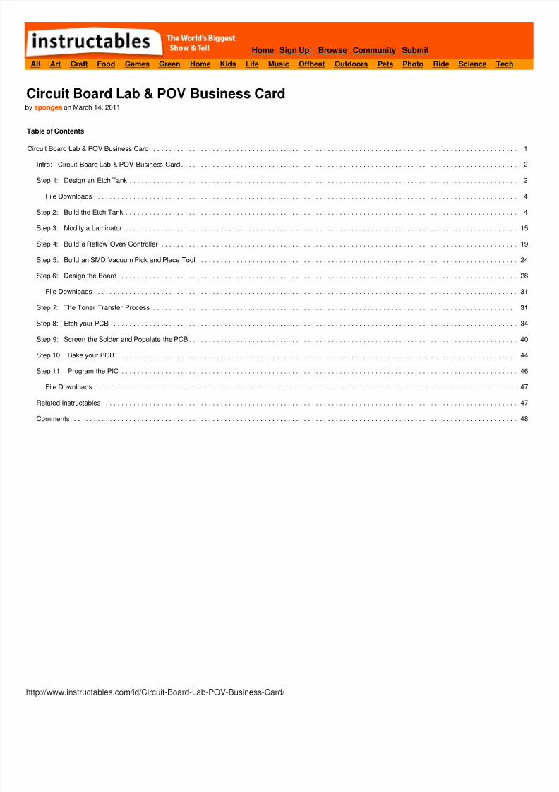
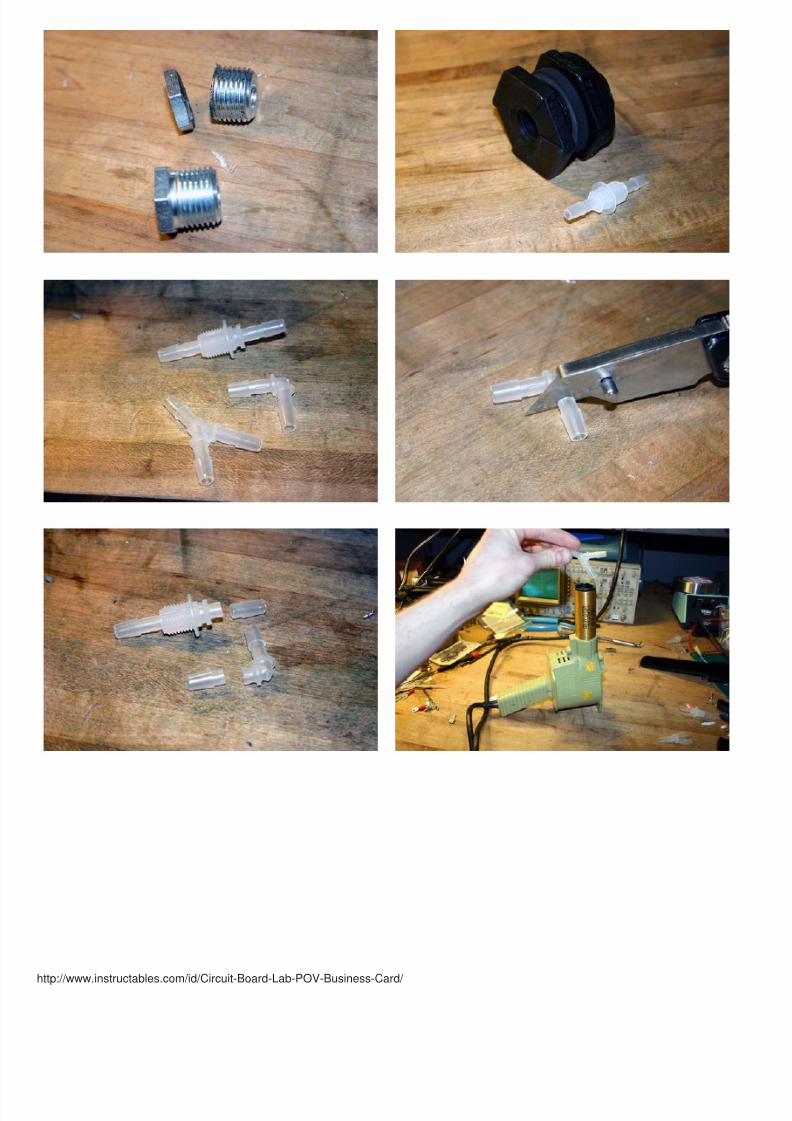
Step 2: Build the Etch TankTo be totally honest, the hardest part of building this thing is just finding the finding the freaking parts. It seems like my entire life is just an endless quest for the parts Ineed.
The most difficult part to find was a pair of bulkhead fittings that were small enough for the tank; small fittings are not common locally, as everything is plumbing sized,and online, the lab grade small fi ttings are only orderable in bulk. Some of these parts are scrounged, most of them I had to order special, and most of them took severounds of searching and receiving of parts that didn't fit together. US Plastics Corporation is the source of pretty much all of it; they are like the Digi Key of tubes and lafittings, as far as I'm concerned. Sources listed where available.
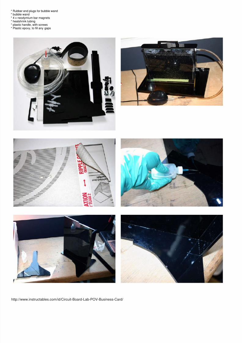
As far as the tank is concerned, the first step is getting it together. The standard for watertight acrylic bonding is Methylene Chloride, which is very nasty stuff, andcancerous, so do it outside. Just leaving a window open is definitely not sufficient. Accordingly, it is pretty hard to find given the recent regulation, so you may have toorder a methylene chloride based glue online, such as IPS Weld-On. I got a tiny little bottle from a friend who does acrylic fabrication professionally.
To be sure, you could probably get by with just the right kind of epoxy, but ideally the parts should be chemically bonded to each other, instead of a mysterious foreignagent.
When bonding parts with Methylene Chloride, you are after as tight a fi t as possible. Laser cut edges need special attention, as they are melted and rounded off. I speabout an hour with a file and sandpaper cleaning up the parts for a good fit.. Even for parts that fit together perfectly from the start, especially the uncut face of the acrit is important to roughen the abutting faces with sandpaper or there is no grab.
Once the parts fit together well, clamp or hold the parts tightly together and run the needle of a syringe or modified squeeze bottle full of the solvent along the crack;capillary action will draw it in. Within about 60 seconds the part will be secure enough to leave alone. It only takes about 30 minutes, for it to set up, sometimes a lot leI left it overnight just to be sure, but it's actually waterproof after about an hour.
After that, you need to make a lid. I cut a self adhesive gasket for both the lid and the lip of the tank to fill the gap, and to seal it up I mounted a pair of wings to either sof the tank with magnets to pull it down and hold it in place. It ends up working so that the lid tends to line itself up, and because the two sides are reversed in polarity,
impossible to put the lid on backwards. I still feel clever about that one. The only caveat is that the magnets need to be sealed in heatshrink tubing to resist corrosion.
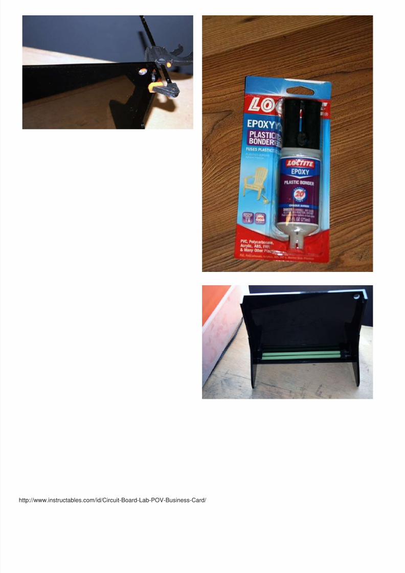
The bulkhead fittings I wanted only came in straight, not 90 degree, so I needed to cut down the one side and weld on an angled fitting. It works surprisingly well withpolypropylene. Its melting point is low enough that a hot air gun does the trick nicely.
Parts
* 1/4 inch acrylic or polycarbonate sheet* EPDM or Viton self adhesive gasket* 1/4" ID Tygon tubing, or high purity PVC* 1 air pump* 1/4" hose barb Polypropylene wye fitting* 1/4" hose barb Polypropylene barbed bulkhead fitting x 2* 1/4" NPT nut (I cut down a steel hex bushing)* 1/4" hose barb Polypropylene check valve* 1/4" hose barb 3/8" NPT HDPE (3/8" fits the bubble wand perfectly)* 1/4" to 1/8" hose bard adapter
8/13/2019 Circuit Board Lab POV Business Card
http://slidepdf.com/reader/full/circuit-board-lab-pov-business-card 5/48
http://www.instructables.com/id/Circuit-Board-Lab-POV-Business-Card/
* Rubber end plugs for bubble wand* bubble wand* 4 x neodymium bar magnets* heatshrink tubing* plastic handle, with screws* Plastic epoxy, to fill any gaps
8/13/2019 Circuit Board Lab POV Business Card
http://slidepdf.com/reader/full/circuit-board-lab-pov-business-card 6/48
http://www.instructables.com/id/Circuit-Board-Lab-POV-Business-Card/

8/13/2019 Circuit Board Lab POV Business Card
http://slidepdf.com/reader/full/circuit-board-lab-pov-business-card 7/48
http://www.instructables.com/id/Circuit-Board-Lab-POV-Business-Card/

8/13/2019 Circuit Board Lab POV Business Card
http://slidepdf.com/reader/full/circuit-board-lab-pov-business-card 8/48
http://www.instructables.com/id/Circuit-Board-Lab-POV-Business-Card/
8/13/2019 Circuit Board Lab POV Business Card
http://slidepdf.com/reader/full/circuit-board-lab-pov-business-card 9/48
http://www.instructables.com/id/Circuit-Board-Lab-POV-Business-Card/

8/13/2019 Circuit Board Lab POV Business Card
http://slidepdf.com/reader/full/circuit-board-lab-pov-business-card 10/48
http://www.instructables.com/id/Circuit-Board-Lab-POV-Business-Card/
8/13/2019 Circuit Board Lab POV Business Card
http://slidepdf.com/reader/full/circuit-board-lab-pov-business-card 11/48
http://www.instructables.com/id/Circuit-Board-Lab-POV-Business-Card/

8/13/2019 Circuit Board Lab POV Business Card
http://slidepdf.com/reader/full/circuit-board-lab-pov-business-card 12/48
http://www.instructables.com/id/Circuit-Board-Lab-POV-Business-Card/
8/13/2019 Circuit Board Lab POV Business Card
http://slidepdf.com/reader/full/circuit-board-lab-pov-business-card 13/48
http://www.instructables.com/id/Circuit-Board-Lab-POV-Business-Card/
8/13/2019 Circuit Board Lab POV Business Card
http://slidepdf.com/reader/full/circuit-board-lab-pov-business-card 14/48
http://www.instructables.com/id/Circuit-Board-Lab-POV-Business-Card/

8/13/2019 Circuit Board Lab POV Business Card
http://slidepdf.com/reader/full/circuit-board-lab-pov-business-card 15/48
http://www.instructables.com/id/Circuit-Board-Lab-POV-Business-Card/
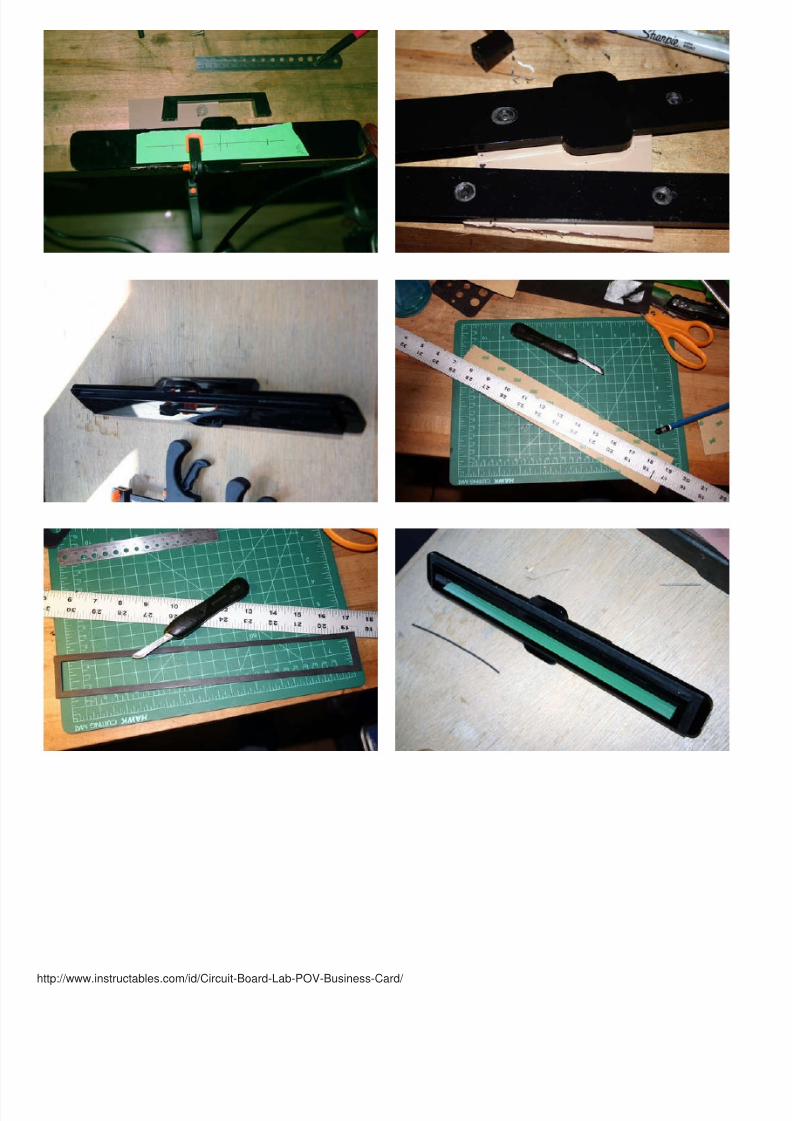
Step 3: Modify a LaminatorTo create positive etch resist mask, the most straight-forward approach , with components readily and cheaply available, is what is known as the Toner Transfer meth
The basic idea is that you print out your design onto a glossy paper and apply the printout to your board with heat and pressure, as evenly as possible. The paper isremoved, leaving only the toner as an etch resist, thereby protecting the copper below from the acid bath.
There are a lot of variables involved, so it is easy to see why a lot of people give up on it. Given enough time, though, it is very possible to get the process dead on. If yhave tried and given up on this method before, I'd recommend that you keep trying, because the payoff in time and money saved is well worth it.
The most important part of the process is the perfect balance between heat and pressure, consistent over the entire board. Proper pressure is easily achieved with astandard bag laminator. You just need to be sure to find one with heated rollers or you won't get the same results. GBC makes two commonly available models, the GCreative and the GBC Personal; they are functionally identical, except that the Personal has an extra switch.
Now all we need is to get the temperature right. Since both of the GBC laminators I mentioned are controlled by a simple thermal switch, all we have to do is swap it owith a switch one with a higher temperature rating. It's pretty simple; the switch closes when the rollers are too hot and opens when it's too cold.
In my case, though, I was able to find a variable thermal switch. Just like a fixed value thermal switch, it uses a bimetallic strip that warps with the changes intemperature. The two metals have two dif ferent coefficients of thermal expansion, and the whole piece bends forward at the proper temperature to close the contact. Unlike a fixed value switch, however, it has a screw that can be adjusted, changing the tension on the bimetallic strip, and thus changing the distance it has to t ravel tclose the contact, and turn on the heater. It's all very clever and simple and perfect for our laminator; we can calibrate it to our hearts desire, even to the point of matchit to the melting point of the toner from the specific model of printer we use. Huzzah!
For safety's sake, we will have to swap out the low temperature thermal fuse (as opposed to bypassing it entirely. Definitely not recommended!) with one of a higherrating, so the whole unit wil l lose power if it overheats and hopefully doesn't catch fire. BTW, you do this mod at your own risk, so don't leave it on unsupervised! It's kidangerous.
My laminator is set to around 180 degrees C (356 F). It varies +/- about 10 degrees, tested wi th a handy thermocouple directly on the rollers, taking care, of course, nolet the probe get pulled into the laminator. The fuse is for 240 C, for a good safe margin.
Parts
* GBC Creative/Personal Laminator* Variable temperature thermal switch, roughly 100-200 degree C* Crimp-on butt connectors* Crimp-on screw terminal connectors, with appropriate sized miniature screw/nut* 240 C thermal fuse

8/13/2019 Circuit Board Lab POV Business Card
http://slidepdf.com/reader/full/circuit-board-lab-pov-business-card 16/48
http://www.instructables.com/id/Circuit-Board-Lab-POV-Business-Card/

8/13/2019 Circuit Board Lab POV Business Card
http://slidepdf.com/reader/full/circuit-board-lab-pov-business-card 17/48
http://www.instructables.com/id/Circuit-Board-Lab-POV-Business-Card/

8/13/2019 Circuit Board Lab POV Business Card
http://slidepdf.com/reader/full/circuit-board-lab-pov-business-card 18/48
http://www.instructables.com/id/Circuit-Board-Lab-POV-Business-Card/

8/13/2019 Circuit Board Lab POV Business Card
http://slidepdf.com/reader/full/circuit-board-lab-pov-business-card 19/48
http://www.instructables.com/id/Circuit-Board-Lab-POV-Business-Card/
Step 4: Build a Reflow Oven ControllerYou may have noticed a trend here toward automation, and I don't deny it. This whole project was an attempt at small scale mass production, if you'll pardon theoxymoron. So here we go: instead of hand soldering every board, hey, guess what- I can just stencil on solder paste, glob it on real good sorta, and stuff the whole thiin a toaster for a minute or two?
Yup, that's the general idea.
The part that makes this possible is choosing Surface Mount (SMD) components over conventional (though now antiquated) through-hole components. They aresignificantly smaller and less expensive that thier larger counterparts. There are no holes to dri ll, and board size is reduced. In any case, I'll spare you the hard sell, asyou probably are already aware of their advantages. Any disadvantages they have are just side effects of their advantages simply being too advantageous: somecomponents can be too small for the home hobbyist to manipulate without the proper tools.
Regardless, the higher entry cost is outweighed by the longterm advantages, so it's time to build a reflow oven so I don't need to get carpal tunnel soldering hundred olittle grains of sand.
Typical SMT fabrication works like this: solder paste is spread through a stencil unto the solder pads of the board. Then the components are stuck into the paste, and entire thing is ramped at a set rate to several set temperature points, depending on the solder and heat resistance of the components. In our case, every componentexcept two can be baked; the battery and the switch need to be hand soldered later.

8/13/2019 Circuit Board Lab POV Business Card
http://slidepdf.com/reader/full/circuit-board-lab-pov-business-card 20/48
http://www.instructables.com/id/Circuit-Board-Lab-POV-Business-Card/
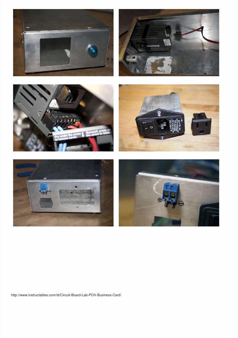
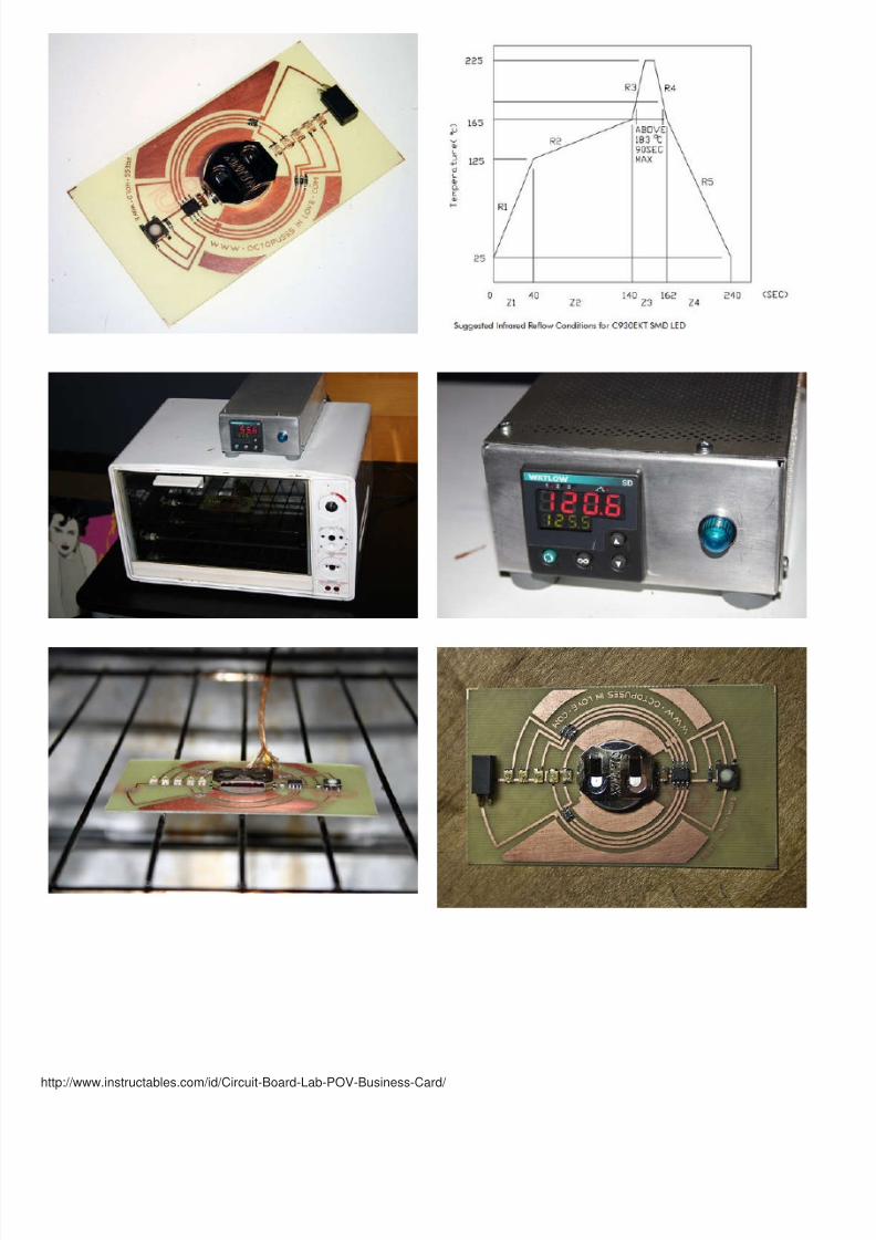
The cheapest commercially available reflow oven is certainly several thousand dollars. On the other end of the spectrum, the cheapest stand alone controllers are in t$100 range. Since the expensive ones are too expensive, and the cheap ones are too crippled, I had to build my own.
All the controller has to do is monitor the temperature of the oven and change it when it need to be changed. The ideal way to do this is with a Ramp/Soak temperaturcontroller, used in factory automation for just such a purpose. I was lucky enough to get a Watlow SD6R-LCJE-AARG ramp./soak controller for less than 50 dollars, anjust built the whole thing around it. YOu should be able to find something similar in the same price range without too much troule.Just make sure it can ramp thetemperature to multiple setpoints, as opposed to simply maintaining one stable temperature.
The Walow is pretty forgiving; it will take 24 AC/DC as power input it can display temperature in Fahrenheit of Celsius, and i t accepts almost any type of thermocoupleMore importantly, It has low voltage DC as a control output that we will use to drive a solid state relay, which will in turn switch on and off the heaters of a standard toaoven.
Any toaster oven will work, though the smaller the better, as the smaller volume of air will mean it can heat up much faster. Try and look for a newer oven with quartzheaters, but ceramic heaters would also be suitable. If your oven has a setting for always on, such as bake, all you need to do is drill a hole in the back for thethermocouple and the oven itself is done. Otherwise, you will need to open it up and wire the heaters to always be on - a dangerous affair that I would not recommend
You'll also need a thermocouple with a heat-resistant insulation, as our oven will reach temperatures of 260 degrees Celsius. This presents yet another fire hazard, sodon't leave it unattended, keep it away from the walls, and don't set anything on it.
Parts
* Old toaster oven, preferably small, with four quartz heating elements* Metal project enclosure* Ramp/Soak Temperature Controller* 10A or greater Solid State Relay, Crydom d2410f* High temp thermocouple
8/13/2019 Circuit Board Lab POV Business Card
http://slidepdf.com/reader/full/circuit-board-lab-pov-business-card 21/48
http://www.instructables.com/id/Circuit-Board-Lab-POV-Business-Card/

8/13/2019 Circuit Board Lab POV Business Card
http://slidepdf.com/reader/full/circuit-board-lab-pov-business-card 22/48
http://www.instructables.com/id/Circuit-Board-Lab-POV-Business-Card/

8/13/2019 Circuit Board Lab POV Business Card
http://slidepdf.com/reader/full/circuit-board-lab-pov-business-card 23/48
http://www.instructables.com/id/Circuit-Board-Lab-POV-Business-Card/
8/13/2019 Circuit Board Lab POV Business Card
http://slidepdf.com/reader/full/circuit-board-lab-pov-business-card 24/48
http://www.instructables.com/id/Circuit-Board-Lab-POV-Business-Card/
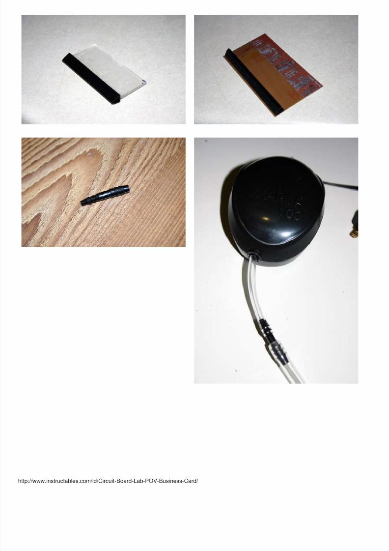
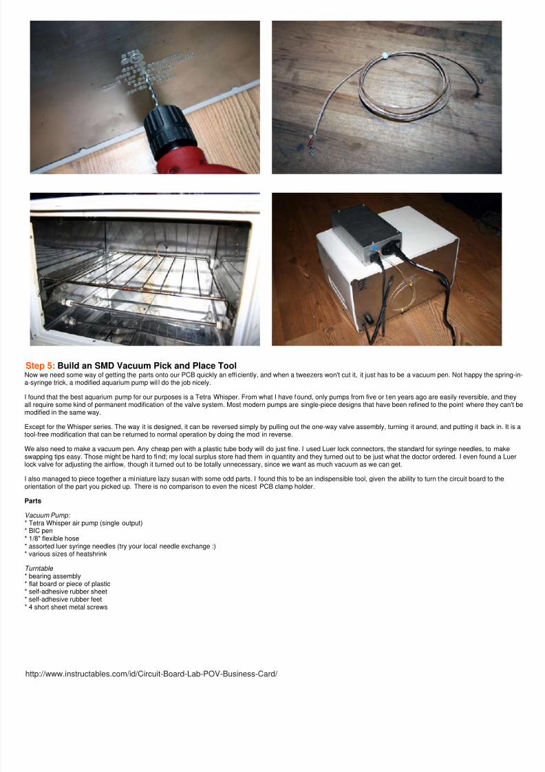
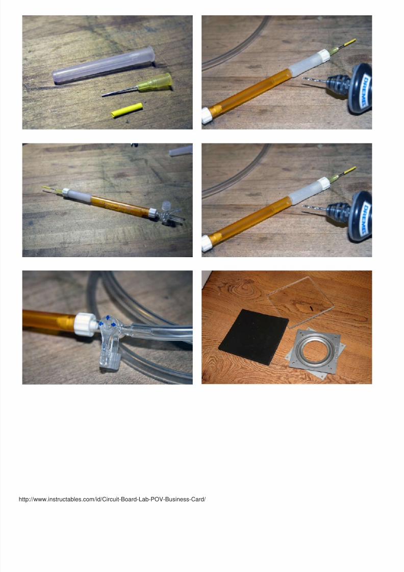
Step 5: Build an SMD Vacuum Pick and Place ToolNow we need some way of getting the parts onto our PCB quickly an efficiently, and when a tweezers won't cut it, it just has to be a vacuum pen. Not happy the springa-syringe trick, a modified aquarium pump wil l do the job nicely.
I found that the best aquarium pump for our purposes is a Tetra Whisper. From what I have found, only pumps from five or ten years ago are easily reversible, and the
all require some kind of permanent modification of the valve system. Most modern pumps are single-piece designs that have been refined to the point where they canmodified in the same way.
Except for the Whisper series. The way it is designed, it can be reversed simply by pulling out the one-way valve assembly, turning it around, and putting it back in. It itool-free modification that can be returned to normal operation by doing the mod in reverse.
We also need to make a vacuum pen. Any cheap pen with a plastic tube body will do just fine. I used Luer lock connectors, the standard for syringe needles, to makeswapping tips easy. Those might be hard to find; my local surplus store had them in quantity and they turned out to be just what the doctor ordered. I even found a Luelock valve for adjusting the airflow, though it turned out to be totally unnecessary, since we want as much vacuum as we can get.
I also managed to piece together a miniature lazy susan with some odd parts. I found this to be an indispensible tool, given the ability to turn the circuit board to theorientation of the part you picked up. There is no comparison to even the nicest PCB clamp holder.
Parts
Vacuum Pump: * Tetra Whisper air pump (single output)* BIC pen
* 1/8" flexible hose* assorted luer syringe needles (try your local needle exchange :)* various sizes of heatshrink
Turntable * bearing assembly* flat board or piece of plastic* self-adhesive rubber sheet* self-adhesive rubber feet* 4 short sheet metal screws

8/13/2019 Circuit Board Lab POV Business Card
http://slidepdf.com/reader/full/circuit-board-lab-pov-business-card 25/48
http://www.instructables.com/id/Circuit-Board-Lab-POV-Business-Card/

8/13/2019 Circuit Board Lab POV Business Card
http://slidepdf.com/reader/full/circuit-board-lab-pov-business-card 26/48
http://www.instructables.com/id/Circuit-Board-Lab-POV-Business-Card/
8/13/2019 Circuit Board Lab POV Business Card
http://slidepdf.com/reader/full/circuit-board-lab-pov-business-card 27/48
http://www.instructables.com/id/Circuit-Board-Lab-POV-Business-Card/

8/13/2019 Circuit Board Lab POV Business Card
http://slidepdf.com/reader/full/circuit-board-lab-pov-business-card 28/48
http://www.instructables.com/id/Circuit-Board-Lab-POV-Business-Card/
Step 6: Design the BoardThis really was the most time consuming step; that is, designing and planning the entire device. First things first: Design requirements: The goal is to make a 5 LEDmicrocontroller-based circuit with a small enough part count to fit on a 2" by 3.5" standard business card. It has to be a single sided board to reduce complexity, and it to be entirely surface mount components to save on time drilling holes, keep the profi le as thin as possible, and keep the end user from getting poked by leads stickingout of the bottom.
Most importantly, it needs to be cheap and quick to make. Again, that means a reduced parts count and surface mount components.
I ended up designing the whole thing around the Microchip PIC12F508 , the smallest, cheapest microcontroller I could find with the right number of pinouts. At the timewriting, they run around 46 cents apiece. Similar chips are available from ATMEL, under the AVR banner, and are more full featured, but cost about twice as much. Anin the quantities I want, that matters.
The PICF508 is no supercomputer. An ironic statement, and given the expectations what most people have of a device this size, it is a supercomputer. But relativelyspeaking, it is very, very simple. It runs nominally at 4MHz on its internal oscillator. It has only 750 bytes of program memory, and 25 bytes of RAM, but we don't needthat much, anyway. It also does not have interrupts or PWM, but, again, we can get by without those. As far as I/O goes, i t has exactly enough. There are 8 pins, two fpower, and 6 I/O pins, one of which is input only. We already know what that means: It will have five LEDs and one sensor, and that's it. The most important feature isthat it is programmable in-circuit (ICSP), meaning you don't have to take it off the board to reprogram it; an important point when you are dealing with a soldered on Spart.
That decision made, the rest comes easy, up to a point. Aside from the five LEDs and their current limiting resistors, a ball-switch that pulls Pin 4 (GP3) low when the tboard is tilted, a bypass capacitor across pin 1 and 8 (.1 uF C1) to prevent erratic CPU behavior, and a momentary power switch to prevent battery drain, there isn't mto it. It's simple, as promised. And with the right program, it can do anything! Anything at all. The only limit is yourself!
I spent a bit of time obsessing about the other components; I ordered about 20 different tactile switches from DigiKey to find the thinnest, nicest looking, softest feelingtactile switch possible. SInce the battery wil l overheat (and potentiall explode) if soldered to, I played around with conductive epoxy and conductive tape, with no luck. the end I bit the bullet and paid the 26 cents apiece of nice, solid, SMD battery retaining clips. They ended up fitting into the design fairly well, too.
Now all there is to do is obsess about the artistry of the PCB layout, and we're done. Ironically, I put more time into proportion and layout than anything else on thisproject, and it gets three sentences of description.
Well, the thing does have be pretty, after all.

8/13/2019 Circuit Board Lab POV Business Card
http://slidepdf.com/reader/full/circuit-board-lab-pov-business-card 29/48
http://www.instructables.com/id/Circuit-Board-Lab-POV-Business-Card/

8/13/2019 Circuit Board Lab POV Business Card
http://slidepdf.com/reader/full/circuit-board-lab-pov-business-card 30/48
http://www.instructables.com/id/Circuit-Board-Lab-POV-Business-Card/

8/13/2019 Circuit Board Lab POV Business Card
http://slidepdf.com/reader/full/circuit-board-lab-pov-business-card 31/48
http://www.instructables.com/id/Circuit-Board-Lab-POV-Business-Card/
File Downloads
POV card schematic 1.1.ai (83 KB)[NOTE: When saving, if you see .tmp as the file ext, rename it to 'POV card schematic 1.1.ai']
POV Card - PCB 7.ai (1 MB)[NOTE: When saving, if you see .tmp as the file ext, rename it to 'POV Card - PCB 7.ai']
POV Card - PCB 7 - layers.ai (1 MB)[NOTE: When saving, if you see .tmp as the file ext, rename it to 'POV Card - PCB 7 - layers.ai']
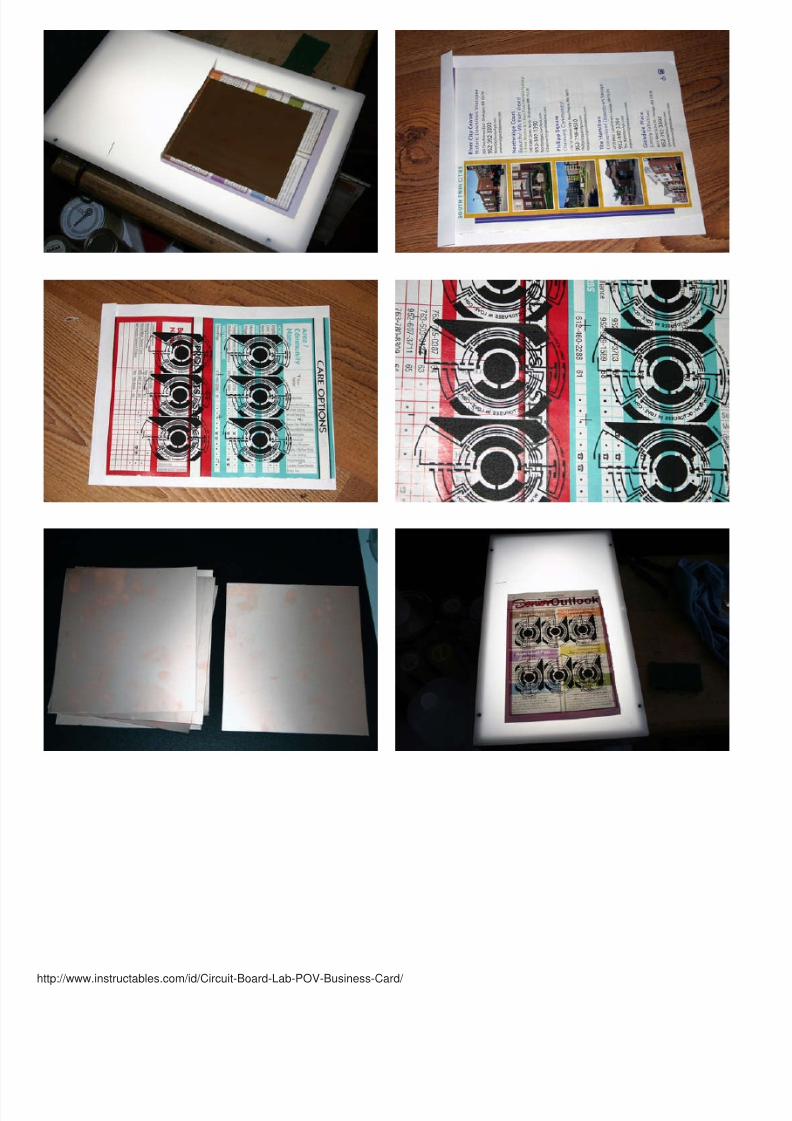
Step 7: The Toner Transfer ProcessLaminator in hand, now we need to use it. This is the f irst step of actual PCB fabrication; everything else was just foreplay.
The first step is to print a transfer onto suitable paper. If you are sufficiently bankrolled, you could use the commercial product made by Pulsar Pro , at about 10 cents sheet, or if you're feeling thri fty you can go the DIY Route, which is free. I don't know why I would even question that, though. Sorry.
Finding the right free (or cheaper) paper can be tricky. The two key characteristics are its ability to hold on to the toner when printed on and its ability to release it wheheated. One predictor of this is how glossy the paper is; more glossy, better release, less glossy, means better hold. We need a happy medium.
People on the internet will recommend all kinds of weird store brand glossy photo papers that are long discontinued, or have to be imported from overseas. Some peohave had success using the waxy backing on shipping labels, suggesting you buy them, and then peel off all the labels, or use them and then save them. Most freepapers are associated with the need to rub and peel and soak the boards just to get the paper off.
Forget that, if I am going to compromise it has to be actually free, not just less expensive than the real thing. I have tried many, many things. As it turns out, a Menard'coupon mailer turned out to give me the best results out of everything. I stopped getting the junk mailings, and they only had a few strangely sized pages eash, so I hato find a more consistently available but similar paper. The best analogue so far is the glossy Apartments For Rent listings they have at the grocery store in the freeliterature rack. It works remarkably well; It prints without toner loss, and when you run it under hot water, it releases instantly. Presto!
The paper is too thin to run through the Laser printer by itself, so you need to make a carrier out of regular white paper by folding over and creasing other top of one s
At this point I should mention the printer itself. For the most part, your final resolution, board quality, and minimum feature size is limited by the resolution of your printeotherwise, any black and white laser printer will work as well as any other. Toner density should be set to the maximum level, and hopefully you have a printer that hassingle-page slot in it so you can just feed the page in by hand.
One caveat, that I discovered too late: the standard Brother brand toner reputedly melts at a higher temperature than other kinds of printers, so I had to get an offbrand refilled cartridge that uses standard temperature toner to get consistent results. So far so good, though. It was a cheap fix, given that I specifically had to buy thebrand stuff.
Once the transfer is printed, you need to line up your PCB, precut to size, to your alignment marks, and here it really helps to have a light table so you can see thoughtransfer paper. Fold over one edge of the transfer, crease it, making sure that it doesn't move, and feed i t creased end into the preheated laminator.I have not noticed differences in adhesion based on transfer paper side-down or side-up, though I use very thin PCB. You may notice a difference for thicker PCBs.
The board is pulled through about 1/4 " per second. I usually run it though about three times, with no time for the board to cool between passes. Of course, the numbepasses will vary quite a bit depending on board thickness, the kind of toner, type of paper, and laminator settings.
Now to the sink where a stream of hot water is ready and waiting. The paper should peel right off after about 10 seconds, though the finer details will need a quickrubdown to clean off the remaining pulp.
And it's ready to etch!

8/13/2019 Circuit Board Lab POV Business Card
http://slidepdf.com/reader/full/circuit-board-lab-pov-business-card 32/48
http://www.instructables.com/id/Circuit-Board-Lab-POV-Business-Card/
8/13/2019 Circuit Board Lab POV Business Card
http://slidepdf.com/reader/full/circuit-board-lab-pov-business-card 33/48
http://www.instructables.com/id/Circuit-Board-Lab-POV-Business-Card/

8/13/2019 Circuit Board Lab POV Business Card
http://slidepdf.com/reader/full/circuit-board-lab-pov-business-card 34/48
http://www.instructables.com/id/Circuit-Board-Lab-POV-Business-Card/
Step 8: Etch your PCBAh, the most immediately hazardous step. This one involves a bit of chemistry, and if done without the proper precautions could be very dangerous. Be careful! You dthis one at your own risk, so wear proper protective equipment (goggles, face shield, rubber gloves) and dfinitely don't do this anywhere near your kitchen.
It's time to make the magic happen! This is the part where we get to break out that badass etch tank we made earlier and pump out hundreds of circuit boards.
The key ingredient for this to work is some kind of etchant. As i mentioned before, I decided on CuCl2 (Cupric Chloride). It is reusable, very cheap, and can be made freadily available chemicals. It is a very good alternative to Ferric Chloride, a common hobby etchant that is not easily regenerated and is quite expensive for a one timuse product. Surprisingly, it is fairly commonly used in the PCB industry, as much or possibly even more so than Ferric Chloride.
The best hobbyist paper on the etchant is Etching with Air Regenerated Acid Cupric Chloride , and there are other Instructables that go into detail on it as well. The firpaper is a must-read.
There is just not enough space here to go into any major detail on the chemistry, and this is covered in far greater detail in the those two links so I wil l breeze over mo it. Suffice it to say that those should be you major references.
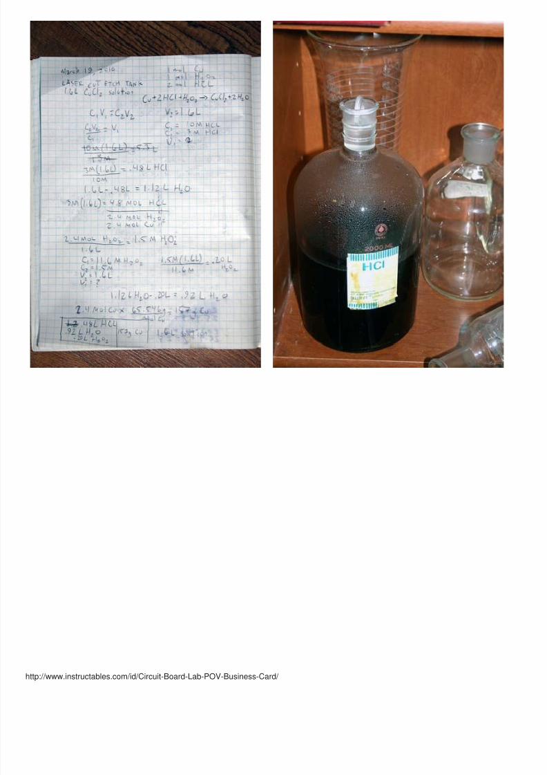
Simply put, given the right amounts of oxygen, HCl (Hydrochloric acid, or Muriatic Acid), copper, and water, we will have a perfect amount of etchant.

8/13/2019 Circuit Board Lab POV Business Card
http://slidepdf.com/reader/full/circuit-board-lab-pov-business-card 35/48
http://www.instructables.com/id/Circuit-Board-Lab-POV-Business-Card/
The reaction we want to happen is:Cu + 2 HCl + H2O2 --> CuCl2 + 2H2O
The copper comes, initially, from the circuit board itself. Hydrochloric acid is commonly available as a pool cleaner, sold as Muriatic Acid. Mine can as 31.45% (20 degBaume, or 10.01 Molar). Hydrogen Peroxide can be found in higher concentrations at health food stores. You want 35% Food grade (11.6 Molar); the 3% kind you getthe first aid section just won't cut it. You also need a jug of distilled water, as tap water is just too impure.
For my 2 L tank, I only need 1.6 Liters of etchant. The ratios in the above formula, and assuming my etchant should be 3 Molar HCl at its final volume, I came up with.48L HCl, .92L H2O, and .20L H2O2 as my reagents. Add the water, then the Peroxide, then the HCl, And do it outside, in a pyrex dish. It will produce heat and fumefairly violently at first, but as you begin to use the solution to etch boards, the fuming will decrease as it turns to Cupric Chloride.
Note: Do not make the mistake of mixing your etchant in your homemade etch tank. Absolutely do not etch too many boards (side by side) or mix raw copper into youetchant, as i did, especially in an enclosed sealed tank. The reaction will be violently exothermic and fume viscously. It will melt, crack, or break open your etch tank frpressure and heat that is far beyond what is normally produced with a controlled stable etchant. With a sufficient air bubbler, you won't need to mix in the copper initiaanyway. The solution will effectively make itself.
The boards will etch rapidly at f irst, in under a minute, and as the solution begins to become saturated, the etch times will increase to five minutes or more. Once itbecomes unreasonably long, you simply need to add the right amount of acid and/ or run the bubbler for a period to regenerate the solution and decrease etch times.Again, consult the above paper for how to do this properly; it is a very good reference.
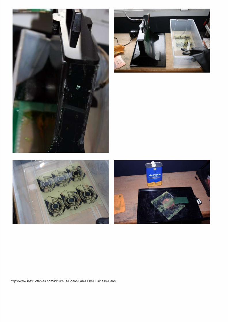
When you can see the board is fully etched, pull it out with plastic tongs, let the excess etchant drip into the tank, and place the board in a plastic dish to rinse it off. Thits on to the Scotch Brite pad and some acetone to take off the layer of toner, and the copper traces should polish up to a bright shine.
When the tank is not in use, the etchant should be stored in an airtight glass vessel that will not be used for food, out of the light, and properly labeled. Under nocircumstances should the etchant be poured down the drain, as it is both toxic and corrosive to metals. If you do happen to spill any, or need to dispose of it, the solutican be neutralized with lime, and mixed with concrete for disposal. Be sure to dispose of it properly, according to your local hazardous waste policy! Where I live theyhave a facility will take in waste like this for free.
8/13/2019 Circuit Board Lab POV Business Card
http://slidepdf.com/reader/full/circuit-board-lab-pov-business-card 36/48
http://www.instructables.com/id/Circuit-Board-Lab-POV-Business-Card/

8/13/2019 Circuit Board Lab POV Business Card
http://slidepdf.com/reader/full/circuit-board-lab-pov-business-card 37/48
http://www.instructables.com/id/Circuit-Board-Lab-POV-Business-Card/

8/13/2019 Circuit Board Lab POV Business Card
http://slidepdf.com/reader/full/circuit-board-lab-pov-business-card 38/48
http://www.instructables.com/id/Circuit-Board-Lab-POV-Business-Card/
8/13/2019 Circuit Board Lab POV Business Card
http://slidepdf.com/reader/full/circuit-board-lab-pov-business-card 39/48
http://www.instructables.com/id/Circuit-Board-Lab-POV-Business-Card/
8/13/2019 Circuit Board Lab POV Business Card
http://slidepdf.com/reader/full/circuit-board-lab-pov-business-card 40/48
http://www.instructables.com/id/Circuit-Board-Lab-POV-Business-Card/
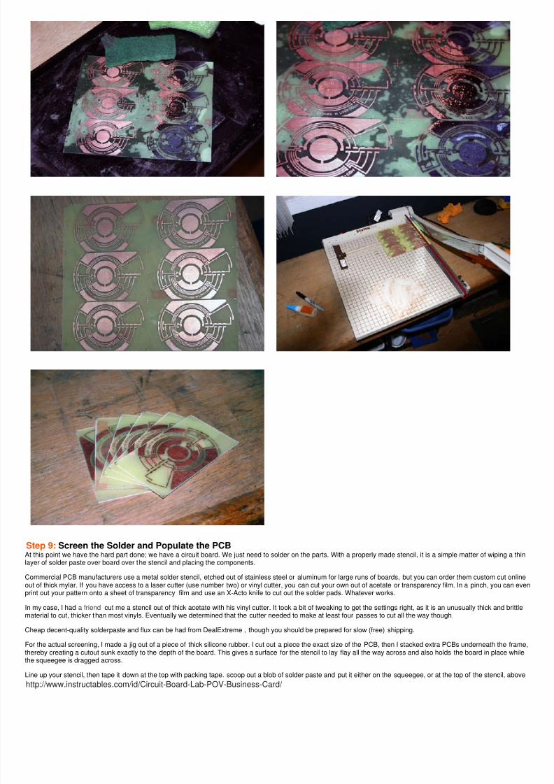
Step 9: Screen the Solder and Populate the PCBAt this point we have the hard part done; we have a circuit board. We just need to solder on the parts. With a properly made stencil, it is a simple matter of wiping a thlayer of solder paste over board over the stencil and placing the components.
Commercial PCB manufacturers use a metal solder stencil, etched out of stainless steel or aluminum for large runs of boards, but you can order them custom cut onlinout of thick mylar. If you have access to a laser cutter (use number two) or vinyl cutter, you can cut your own out of acetate or transparency film. In a pinch, you can evprint out your pattern onto a sheet of transparency film and use an X-Acto knife to cut out the solder pads. Whatever works.
In my case, I had a friend cut me a stencil out of thick acetate with his vinyl cutter. It took a bit of tweaking to get the settings right, as it is an unusually thick and brittlematerial to cut, thicker than most vinyls. Eventually we determined that the cutter needed to make at least four passes to cut all the way though.
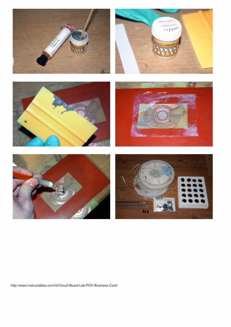
Cheap decent-quality solderpaste and flux can be had from DealExtreme , though you should be prepared for slow (free) shipping.
For the actual screening, I made a jig out of a piece of thick silicone rubber. I cut out a piece the exact size of the PCB, then I stacked extra PCBs underneath the framthereby creating a cutout sunk exactly to the depth of the board. This gives a surface for the stencil to lay flay all the way across and also holds the board in place whilthe squeegee is dragged across.
Line up your stencil, then tape it down at the top with packing tape. scoop out a blob of solder paste and put it either on the squeegee, or at the top of the stencil, abov

8/13/2019 Circuit Board Lab POV Business Card
http://slidepdf.com/reader/full/circuit-board-lab-pov-business-card 41/48
http://www.instructables.com/id/Circuit-Board-Lab-POV-Business-Card/
the cutouts. The Solder paste should be viscous, but not so viscous that it can't be spread. I t's a non-newtonian material, meaning that it holds it flows more easily undpressure, and solidifies somewhat when the pressure is released.
Hold the stencil tight at the bottom and run the squeegee across the stencil, taking care not to lift it off the surface. Repeat until all areas are filled and then carefully peup the stencil.This part definitely takes practice and you will probably have to make several attempts before you get it right.
Now just place the board on a lazy susan and pick and place the appropriate parts with a tweezers or a vacuum pen. Then it's off to the reflow oven, where you hopefdon't bump the board and spill the parts you just meticulously placed all over the floor and have to pick hairs and dir t off the parts because it stuck into the paste still othem.
Parts* Solder paste stencil* solder paste* SIlicone rubber sheet* packing tape* metal or rubber squeegee* X-Acto Knife
8/13/2019 Circuit Board Lab POV Business Card
http://slidepdf.com/reader/full/circuit-board-lab-pov-business-card 42/48
8/13/2019 Circuit Board Lab POV Business Card
http://slidepdf.com/reader/full/circuit-board-lab-pov-business-card 43/48
http://www.instructables.com/id/Circuit-Board-Lab-POV-Business-Card/
8/13/2019 Circuit Board Lab POV Business Card
http://slidepdf.com/reader/full/circuit-board-lab-pov-business-card 44/48
http://www.instructables.com/id/Circuit-Board-Lab-POV-Business-Card/
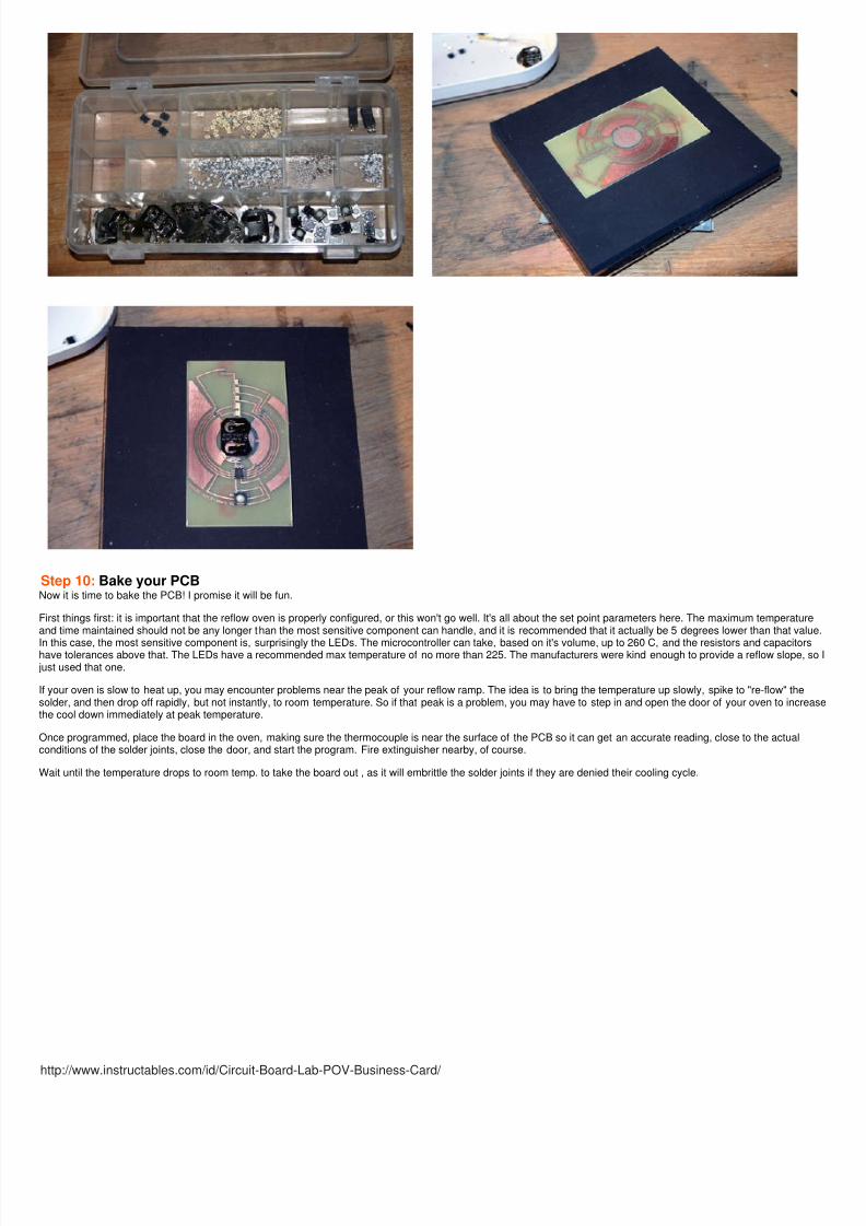
Step 10: Bake your PCBNow it is time to bake the PCB! I promise it will be fun.
First things first: it is important that the reflow oven is properly configured, or this won't go well. It's all about the set point parameters here. The maximum temperatureand time maintained should not be any longer than the most sensitive component can handle, and it is recommended that it actually be 5 degrees lower than that valu
In this case, the most sensitive component is, surprisingly the LEDs. The microcontroller can take, based on it's volume, up to 260 C, and the resistors and capacitorshave tolerances above that. The LEDs have a recommended max temperature of no more than 225. The manufacturers were kind enough to provide a reflow slope, sjust used that one.
If your oven is slow to heat up, you may encounter problems near the peak of your reflow ramp. The idea is to bring the temperature up slowly, spike to "re-flow" thesolder, and then drop off rapidly, but not instantly, to room temperature. So if that peak is a problem, you may have to step in and open the door of your oven to increathe cool down immediately at peak temperature.
Once programmed, place the board in the oven, making sure the thermocouple is near the surface of the PCB so it can get an accurate reading, close to the actualconditions of the solder joints, close the door, and start the program. Fire extinguisher nearby, of course.
Wait until the temperature drops to room temp. to take the board out , as it will embrittle the solder joints if they are denied their cooling cycle.
8/13/2019 Circuit Board Lab POV Business Card
http://slidepdf.com/reader/full/circuit-board-lab-pov-business-card 45/48
http://www.instructables.com/id/Circuit-Board-Lab-POV-Business-Card/

8/13/2019 Circuit Board Lab POV Business Card
http://slidepdf.com/reader/full/circuit-board-lab-pov-business-card 46/48
http://www.instructables.com/id/Circuit-Board-Lab-POV-Business-Card/
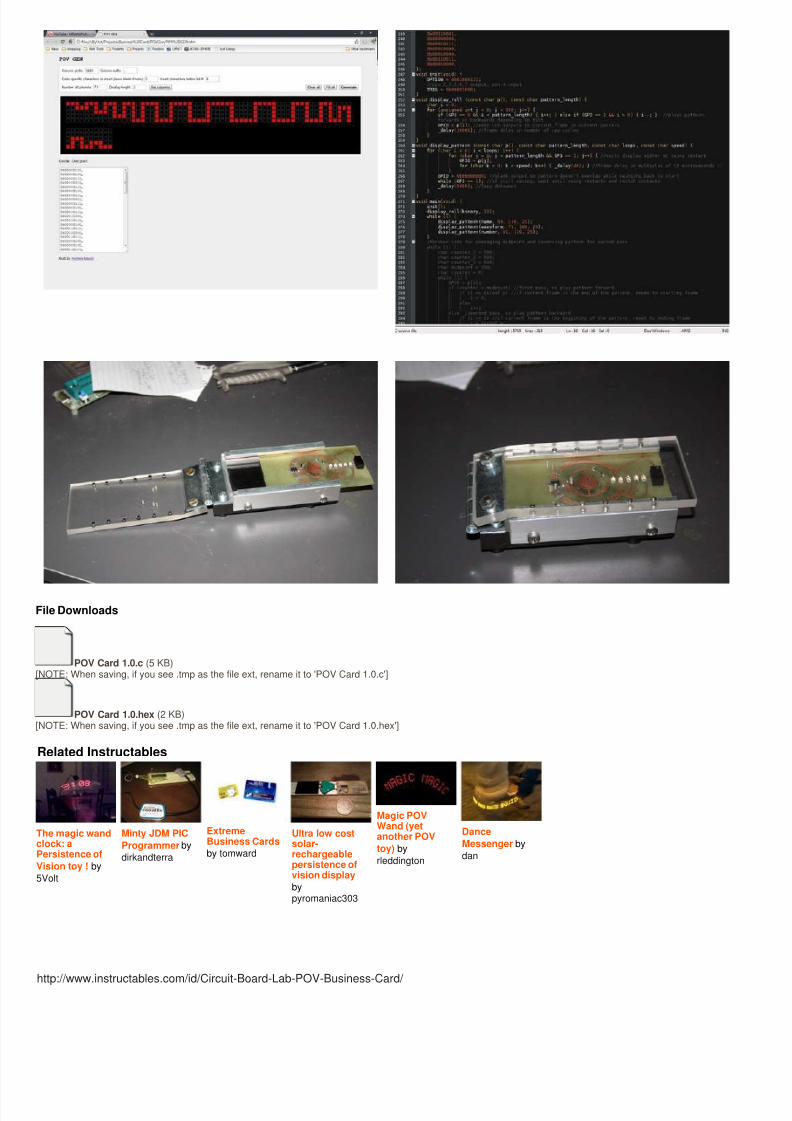
Step 11: Program the PICThe board now complete, we have only to give it a program to run, and it will be ready to set our creation free into the wild!
The PIC can be programmed either in C++ or assembly language. I chose C++, to save time, and because I didn't necessarily want to commit to this architecture. Andadmittedly, because assembly is no fun!
With no interrupts or PWM, the PIC12F508 is nothing fancy, but it definitely gets the job done.
Here's how it works:
The card is off until the momentary on switch is held down. On power up, the program simulates a little rolling ball with a binary counter that rolls in and out with the tiltthe card. After roughly four tilts back and forth, it then switches to Persistence Of Vision mode and cycles through a series of programmed patterns. Currently, it says mname, followed by a neat square wave pattern that acts as a separator, and then my phone number. When the tilt switch closes, the program recognizes that as the stof a wave, and plays the current pattern one time through, then waits until another wave starts. As long as the wave does not double back too soon, and the pattern is
too long, there will be no overlap as the pattern will be blank until it resets.
Each pattern is an array of bytes, each byte a column in the sequence. The time that each column (frame) in the pattern is left on and the time between framesdetermines the speed of the display, and how close the frames are spaced when the card is waved. Basically, it changes the width of the characters and the pattern awhole. Furthermore, the speed at which you wave the card also plays a part in the spacing, but not enough to make it illegible; since it changes frames at a constant rthe variation is not enough to matter, but is enough to make it look dynamic. Neat, huh?
Before you start writing a program, it helps to have a programmer to debug the code with. I have had good luck with the iCP01 USB programmer. Just don't hook up tprogrammer to the board with an external battery attached, or you will fry it.
It is capable of ICSP (In Circuit Serial Programming), which puts the chip in a high voltage programming mode and allows it to be programmed in the circuit, assumingrest of the circuit is relatively isolated. Using that, I make several little jigs. The one for programming surface mount ships simply used a scrap prototype board with SMpads for the IC and wires to the traces coming out of pins. Then I just position the chip and hold it down with my finger while it is being programmed, taking care not toshort out the leads. Alternately it has a magnet underneath the board that holds the ship in place. Because the PIC is entirely flash based, a non magnetic memory, itno effect on the chip.
For when the board is assembled, I also have a programmer that the card slides into, with a swing down lid, and pogo pins that touch down and make contact with speICSP pads on the board.
8/13/2019 Circuit Board Lab POV Business Card
http://slidepdf.com/reader/full/circuit-board-lab-pov-business-card 47/48
http://www.instructables.com/id/Circuit-Board-Lab-POV-Business-Card/
File Downloads
POV Card 1.0.c (5 KB)[NOTE: When saving, if you see .tmp as the file ext, rename it to 'POV Card 1.0.c']
POV Card 1.0.hex (2 KB)[NOTE: When saving, if you see .tmp as the file ext, rename it to 'POV Card 1.0.hex']
Related Instructables
The magic wandclock: aPersistence of
Vision toy ! by
5Volt
Minty JDM PIC
Programmer by
dirkandterra
ExtremeBusiness Cards
by tomward
Ultra low costsolar-rechargeablepersistence ofvision display
bypyromaniac303
Magic POVWand (yetanother POV
toy) by
rleddington
Dance
Messenger by
dan

8/13/2019 Circuit Board Lab POV Business Card
http://slidepdf.com/reader/full/circuit-board-lab-pov-business-card 48/48