circuit simulation: reality and challenges journée...
TRANSCRIPT

Jean-Marc Talbot
Engineering Director DSM/AMS
Circuit simulation: Reality and Challenges
Journée industrielle GDR Recherche Opérationnelle
November 26th;2013

© 2011 Mentor Graphics Corp. Company Confidential
www.mentor.com
Agenda
EDA Industry: brief overview
Mentor Graphics Corporate overview
The Deep Submicron Division (DSM)
Circuit simulation: reality and trends
Challenges of AMS simulation
Research & Innovation
Q & A
Journée industrielle GDR RO; JMT; Novembre 2013 2

© 2011 Mentor Graphics Corp. Company Confidential
www.mentor.com Your Initials, Presentation Title, Month Year
EDA Industry
3 Journée industrielle GDR RO; JMT; Novembre 2013

© 2011 Mentor Graphics Corp. Company Confidential
www.mentor.com
Moore’s Law: IC Complexity Steadily Rises, Creating Opportunities for EDA
Each new design generation creates demand for EDA tools
More licenses of existing tools
New tools and methodologies to address design problems that didn’t exist previously
Replacement of older tools that break (discontinuity)
1979 29,000
Transistors 8088
1982 134,000
Transistors 286
1985 275,000
Transistors 386
1989 1,290,000 Transistors
486
1993 3.1M+
Transistors Pentium
1995 5.5M+
Transistors Pentium Pro
1997 7.5M+
Transistors Pentium II
2000 42M
Transistors Pentium 4
2004 592M
Transistors Itanium 2
(9MB cache)
2002 220M
Transistors Itanium 2
2008
2.0B
Transistors
Tukwila
2010 3B
Transistors 28/22nm design rule
Journée industrielle GDR RO; JMT; Novembre 2013 4

© 2011 Mentor Graphics Corp. Company Confidential
www.mentor.com
Moore and More then Moore: technology trends
5 Journée industrielle GDR RO; JMT; Novembre 2013
More than Moore” ITRS – International Technology Roadmap for Semiconductor White Paper (2010) (http://www.itrs.net/)

© 2011 Mentor Graphics Corp. Company Confidential
www.mentor.com
New design paradigms: 3D IC, SiPhotonics: New EDA tools required for design & verification
6 Journée industrielle GDR RO; JMT; Novembre 2013
Logic Die
Package Substrate
Back Metal Layers
Active Circuitry Top Metal Layers
Top Metal Layers
Memory Die
Active Circuitry
TSV
Top Metal Layers
Silicon
Active Circuitry
Package Substrate
Passive Interposer
Top Metal Layers
Silicon
Active Circuitry
Metal Layers
2.5D Stacking, Interposer
3D Stacking, Die on Die
Maurizio Zuffada STMicroelectronics Photonics 21 - WG6 Workshop Brussels - April 30th, 2013
Silicon Photonics Hybrid IC (PIC): EO 40 Gbps Transceiver

© 2011 Mentor Graphics Corp. Company Confidential
www.mentor.com
What Is Electronic Design Automation?
Critical design software used to create the world’s electronic systems
Comprehensive EDA product portfolios address all levels – from component to systems
7 Journée industrielle GDR RO; JMT; Novembre 2013

© 2011 Mentor Graphics Corp. Company Confidential
www.mentor.com Your Initials, Presentation Title, Month Year
CORPORATE OVERVIEW
8 Journée industrielle GDR RO; JMT; Novembre 2013

© 2011 Mentor Graphics Corp. Company Confidential
www.mentor.com
Mentor Graphics
Electronic design automation (EDA) industry pioneer and global innovator of advanced design solutions
Founded in 1981
Revenue - ~$1.089B
Focused on growth through internal development
Source: EDAC Market Statistics
Journée industrielle GDR RO; JMT; Novembre 2013 9

© 2011 Mentor Graphics Corp. Company Confidential
www.mentor.com
Mentor Graphics Around the World
Journée industrielle GDR RO; JMT; Novembre 2013 10

© 2011 Mentor Graphics Corp. Company Confidential
www.mentor.com Your Initials, Presentation Title, Month Year
DSM OVERVIEW
11 Journée industrielle GDR RO; JMT; Novembre 2013
© 2011 Mentor Graphics Corp. Company Confidential
www.mentor.com
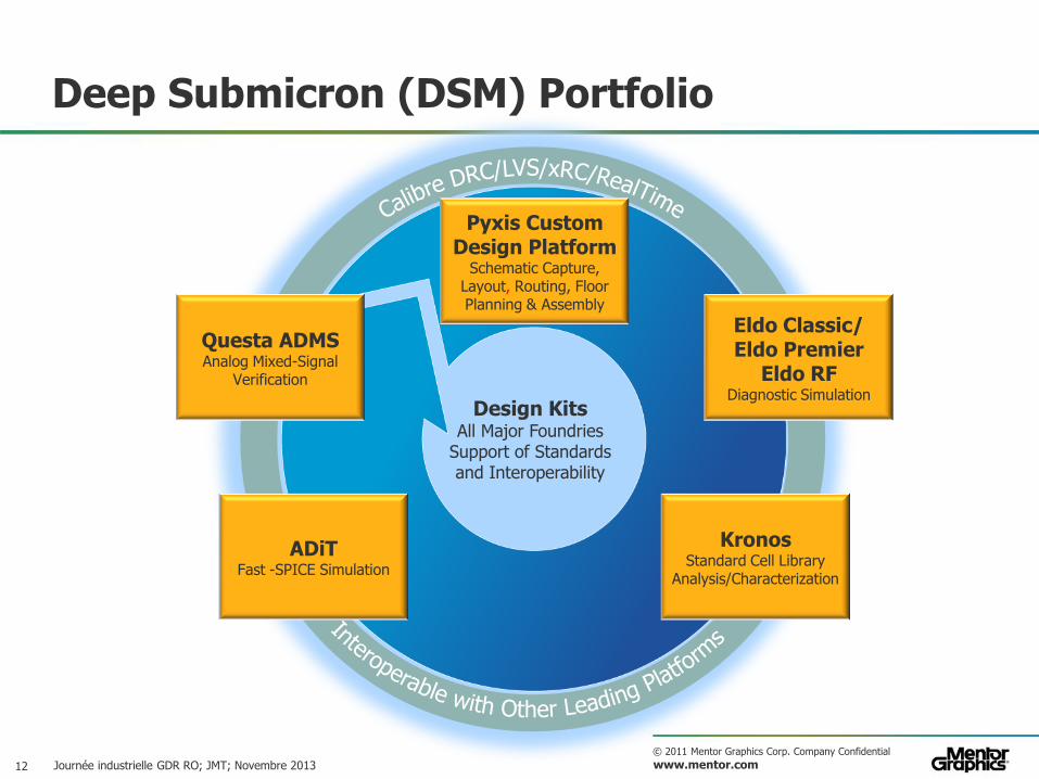
Design Kits All Major Foundries
Support of Standards and Interoperability
Deep Submicron (DSM) Portfolio
Journée industrielle GDR RO; JMT; Novembre 2013
ADiT Fast -SPICE Simulation
Pyxis Custom Design Platform
Schematic Capture, Layout, Routing, Floor Planning & Assembly
Kronos Standard Cell Library
Analysis/Characterization
Eldo Classic/ Eldo Premier
Eldo RF Diagnostic Simulation
Questa ADMS Analog Mixed-Signal
Verification
12

© 2011 Mentor Graphics Corp. Company Confidential
www.mentor.com
Mentor’s Custom IC Solutions Product Portfolio Overview
Pyxis Schematic Design Capture
Calibre® nmDRC/LVS Physical Verification
Calibre® xRC™
Parasitic Extraction
Questa® ADMS, Eldo® Classic and Premier ®
RF, ADiT™
Design Verification
Pyxis Layout IC Layout
Pyxis Custom Router Pyxis Assemble
Floorplan & Assembly
Design Kits All Major Foundries
Support of Standards and Interoperability
INTERACTIVE VERIFICATION
INTERACTIVE ANALYSIS
SCHEMATIC DRIVEN LAYOUT
INTERACTIVE PARASITIC DEBUG
DESIG
N M
AN
AG
ER
DATA M
AN
AG
EM
EN
T
13 Journée industrielle GDR RO; JMT; Novembre 2013
© 2011 Mentor Graphics Corp. Company Confidential
www.mentor.com Your Initials, Presentation Title, Month Year
Circuit Simulation: Reality and Trends
14 Journée industrielle GDR RO; JMT; Novembre 2013

© 2011 Mentor Graphics Corp. Company Confidential
www.mentor.com
Analog simulation
An analog simulator is used to design, verify and characterize analog IP blocks.
It is used by Analog designers. It computes the response of a circuit from its topological description and stimuli.
Journée industrielle GDR RO; JMT; Novembre 2013 15

© 2011 Mentor Graphics Corp. Company Confidential
www.mentor.com
Electronic circuits
An electronic circuit is composed of a (large) set of limited different devices (V, R, L, C, transistors, …)
Compact models are simple for R, L, C, but complex for transistors ( 104 loc)
Each device is represented by a compact models. Algebraic explicit equations describing currents and charges with respect to port voltages: I(V) and Q(V)
Journée industrielle GDR RO; JMT; Novembre 2013 16

© 2011 Mentor Graphics Corp. Company Confidential
www.mentor.com
Basic analyses
AC: linearized, frequency domain response
DC: static operating point
TRAN: time domain response
Journée industrielle GDR RO; JMT; Novembre 2013 17

© 2011 Mentor Graphics Corp. Company Confidential
www.mentor.com
System of equations
The simulator calculates the voltage value of all the nodes of the circuit: N unknowns (very wide range) — Cell Characterization: N 10 to 100 — « regular » IP blocks: N 102 to 105
— Flat display panels: N 106 to 108
Kirchoff Current Law is used to build the system of equations to be solved (sum of currents is null for all nodes): N equations
v: node voltages
i: sum of static currents on each nodes
q: sum of charges on each nodes
u: stimuli
0)())((
))(()),(( tudt
tvdqtvittvf
Journée industrielle GDR RO; JMT; Novembre 2013 18

© 2011 Mentor Graphics Corp. Company Confidential
www.mentor.com
System characteristics
DC: real, non linear, algebraic AC & Noise: complex, linear, algebraic TRAN: real, non linear, algebro-differential RF: complex, non linear, algebraic / algebro-differential Simulation requirements, as usual:
— Speed — Capacity — Accuracy — Scalability on multi-core platforms
Journée industrielle GDR RO; JMT; Novembre 2013 19

© 2011 Mentor Graphics Corp. Company Confidential
www.mentor.com
Circuit simulation trends (1/3)
Market demand to increase by orders of magnitude simulation speed and capacity:
— Accuracy: from « relaxed » to sign-off — Scalability on multi-core architectures
Leading edge designs at 20 nm and below dramatically increase variability effects
Journée industrielle GDR RO; JMT; Novembre 2013 20
• Die to Die
• Inside Die
• Layout Dependant Effects
• Wire parasitics
• Optical corrections
• Dual patterning
• Tiling
• Supply Voltage
• Thermal Variations
• Packaging / Board 3D integration
• Silicon (n/p BTI, HC)
• Interconnect (EM)
Process
Aging Implementation
Environment
Variabi
lity …
Help designers to better control the
predictability of performances in
presence of variability that arises
from chip fabrication or circuit
operation
Identify devices that have a
dominant contribution for
each cause of variability
Courtesy STMicroelectronics

© 2011 Mentor Graphics Corp. Company Confidential
www.mentor.com
Circuit simulation trends (2/3)
Electro Migration
Negative Bias Temperature Instability
Time Dependant Dielectric Breakdown
Hot Carrier Injection
All these issues are
critical from 65nm and below.
All industry sectors are
impacted
military-aerospace communications
consumer automotive

© 2011 Mentor Graphics Corp. Company Confidential
www.mentor.com
Circuit simulation trends (3/3)
Lifetime prediction is a MUST, not an option
Simulation of NBTI and HCI effects in analog and mixed-signal context
Benefits — Accurate & efficient — Prevents over-design — Supports Mixed Signal and RF — Supports Statistical Aging — Supports Aging Sensitivity — Supports specialty processes — Protects Intellectual Property

© 2011 Mentor Graphics Corp. Company Confidential
www.mentor.com Your Initials, Presentation Title, Month Year
CHALLENGES OF AMS SIMULATION
23 Journée industrielle GDR RO; JMT; Novembre 2013
© 2011 Mentor Graphics Corp. Company Confidential
www.mentor.com
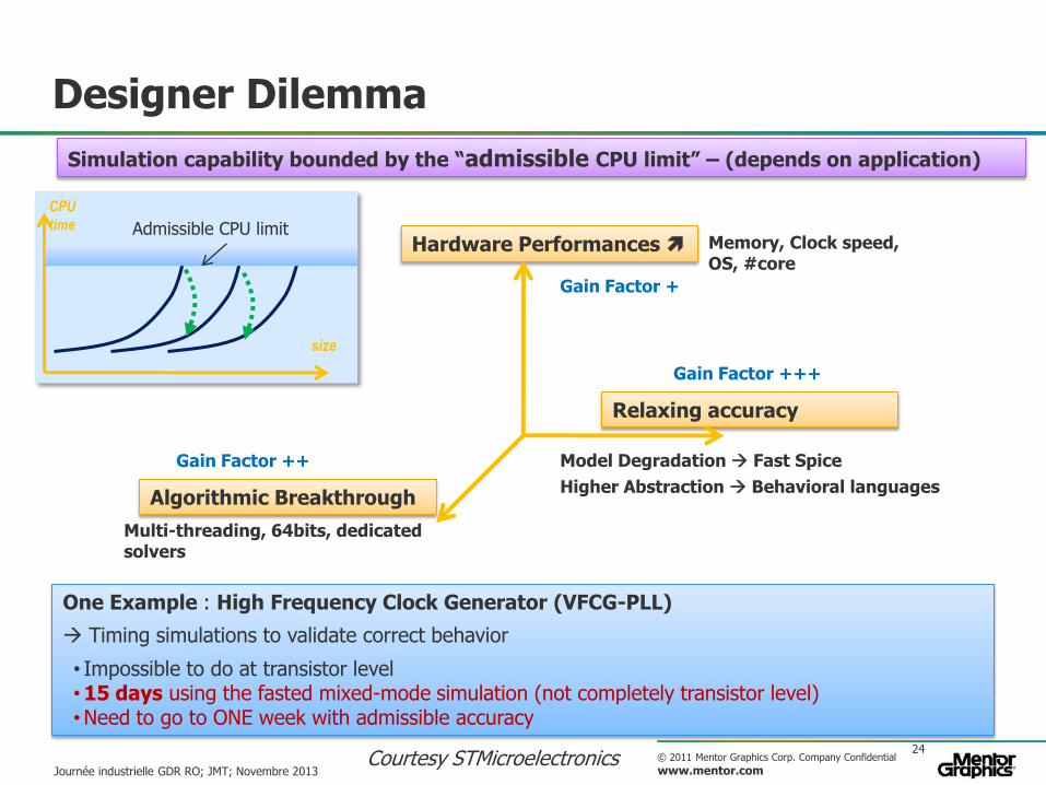
Designer Dilemma
24
Simulation capability bounded by the “admissible CPU limit” – (depends on application)
One Example : High Frequency Clock Generator (VFCG-PLL)
Timing simulations to validate correct behavior
• Impossible to do at transistor level • 15 days using the fasted mixed-mode simulation (not completely transistor level) • Need to go to ONE week with admissible accuracy
Admissible CPU limit
size
CPU
time
Hardware Performances
Algorithmic Breakthrough
Relaxing accuracy
Memory, Clock speed, OS, #core
Multi-threading, 64bits, dedicated solvers
Model Degradation Fast Spice
Higher Abstraction Behavioral languages
Gain Factor +
Gain Factor +++
Gain Factor ++
Journée industrielle GDR RO; JMT; Novembre 2013 Courtesy STMicroelectronics
© 2011 Mentor Graphics Corp. Company Confidential
www.mentor.com
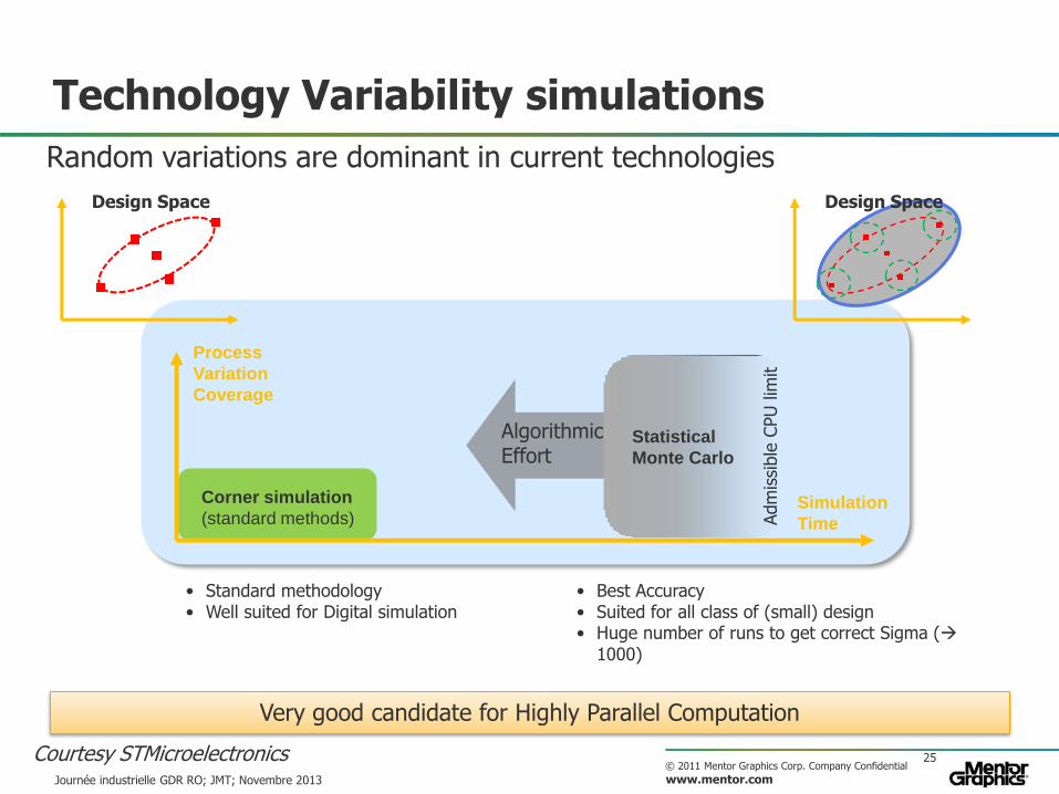
Technology Variability simulations
25
• Standard methodology • Well suited for Digital simulation
• Best Accuracy • Suited for all class of (small) design • Huge number of runs to get correct Sigma (
1000)
Design Space
Process
Variation
Coverage
Simulation
Time
Corner simulation
(standard methods)
Algorithmic Effort
Statistical
Monte Carlo
Design Space
Adm
issi
ble
CPU
lim
it
Random variations are dominant in current technologies
Very good candidate for Highly Parallel Computation
Journée industrielle GDR RO; JMT; Novembre 2013
Courtesy STMicroelectronics

© 2011 Mentor Graphics Corp. Company Confidential
www.mentor.com
Multiple Sources of Variability
Parametric: dimensions (W,L), doping concentration, Tox, Vth, Mobility, …
Environmental: supply voltage Vdd, temperature.
Aging: electro migration, hot carrier injection.
Dimensions Concentration des dopants
Electromigration Injection de porteurs chauds
W,L
Aging
Vdd, Temp

© 2011 Mentor Graphics Corp. Company Confidential
www.mentor.com
Trends for Variability
ITRS (International Technology Roadmap for Semiconductors)
Variability increases as the dimensions shrink
Systematic Variations — Compensation with new lithographic techniques (OPC, PSM, etc.)
Random Variations — No compensation at the manufacturing stage — Must be analyzed and monitored during the entire design flow
0%
10%
20%
30%
40%
50%
60%
70%
2012 2014 2016 2018 2020
Va
ria
bil
ity,
3σ
/µ
Year
Vdd
Vth
Dimensions
critiques
0%
10%
20%
30%
40%
50%
60%
70%
80%
2012 2014 2016 2018 2020
Va
ria
bil
ity,
3σ
/µ
Year
Performance
Consommation
© 2011 Mentor Graphics Corp. Company Confidential
www.mentor.com
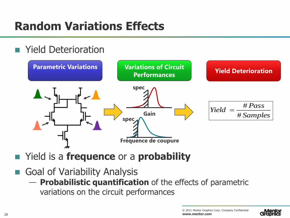
Random Variations Effects
Yield Deterioration
Yield is a frequence or a probability
Goal of Variability Analysis — Probabilistic quantification of the effects of parametric
variations on the circuit performances
Parametric Variations Yield Deterioration
Variations of Circuit
Performances
Samples
PassYield
#
#
Fréquence de coupure
spec Gain
spec
28

© 2011 Mentor Graphics Corp. Company Confidential
www.mentor.com
Methods: Verification and Sensitivity
Performance = Random Variable
– Density of Probability – Moments: mean,spread, shape,… – …
Tools for Characterization – Histogram, Density Plots,… – Statistical Tests (normality, …) – Estimation of Yield – …
Performance
Characterization of Performance
Variations Identification of the Most Important
Sources of Variability
Performance
How to screen out non-important input variations ?
Sensitivity Analysis – Sensitivity nalysis – Interaction analysis with transistor geometries – …
29

© 2011 Mentor Graphics Corp. Company Confidential
www.mentor.com Your Initials, Presentation Title, Month Year
RESEARCH & INNOVATION
30 Journée industrielle GDR RO; JMT; Novembre 2013

© 2011 Mentor Graphics Corp. Company Confidential
www.mentor.com
Overview of a SPICE simulator
Simulation Kernel
Device Model equations
(diode, bsim3v3, bsim4…)
Data Processor • Probing • Measurements/Extracts
• Parser • Elaboration
Simulation database
SPICE circuit description
Simulator commands (analysis, plot…) • Devices
• Topology (nodes…)
• Commands: – Analysis (AC, DC, TRAN…) – Control (STEP, MC, ALTER…) – Output (probe, extract…)
Sparse Matrix Solver
< 10%
~80%
< 10%
Percentage of CPU time
So far, parallelization efforts have been focused here
Conférence Technologique ENSIMAG; JMT; 07/12/2012 31

© 2011 Mentor Graphics Corp. Company Confidential
www.mentor.com
Linear System characteristics
Can be very large (several millions of rows/columns)
Very sparse in general, but can be denser (with back-annotated circuits / parasitics)
No specific structure
Can be singular or ill-conditionned
The simulator performance is directly related to the efficiency of the linear solver !

© 2011 Mentor Graphics Corp. Company Confidential
www.mentor.com
The linear solver (A.x = b)
General purpose linear solvers are not efficient enough.
Dedicated sparse LU with fill-in minimization techniques (matrix reordering). — Used now for more than 30 years. — Well suited for small/medium size circuits,
standard applications — Limited scalability
Iterative solvers (Krylov subspace,….). — Could be suited for large size and back-
annotated circuits — Requires a specific preconditionner

© 2011 Mentor Graphics Corp. Company Confidential
www.mentor.com
Domain decomposition techniques: hierarchical block diagonal bordered matrices — Graph theory for the partitionning — Hierarchical Schur complement resolution — More suitable for parallel computation,
better scalability
Additional speed_up: — Partial solve (bypass of the inactive part of
the circuit) — Isomorphism matching, solver sharing, state
sharing — Direct (assembly) code generation
The linear solver (A.x = b), new trends

© 2011 Mentor Graphics Corp. Company Confidential
www.mentor.com
Innovation & new products: Eldo Premier
Hierarchical Recursive Resolution
Multi Threading
Linear Algebra
Compiled Solvers
HR2 is a fundamental architectural breakthrough
Equation formulation radically different from traditional SPICE
Allows more scalable Multi-Threading, smarter Linear Algebra and optimized hardware usage
Key Technology Concept : HR2
Journée industrielle GDR RO; JMT; Novembre 2013 35

© 2011 Mentor Graphics Corp. Company Confidential
www.mentor.com
Traditional Multi-Threading
Traditionally, the parts of the solutions that are multi-threaded are : — Device evaluations : PSP,
BSIM4,… — Matrix LU decomposition
This leaves LOTS of 100% sequential code, and thus severely limits scalability
Device evaluations
Matrix loading
RHS1 assembly
Matrix Solving
Convergence Control
LTE2 Control
Journée industrielle GDR RO; JMT; Novembre 2013
1 – Right Hand Side 2 – Local Truncation Error
Multi-threaded Sequential
36

© 2011 Mentor Graphics Corp. Company Confidential
www.mentor.com
HR2 Enabled Multi-Threading
In contrast, HR2 formulation allows much more pervasive Multi-Threading
Scalability of the MT gain is much better
Device evaluations
Matrix loading
RHS1 assembly
Matrix solving
Convergence Control
LTE2 Control
1
2
3
4
5
6
7
8
1 2 3 4 5 6 7 8
SPEEDUP (#CORES)
1 – Right Hand Side 2 – Local Truncation Error
Premier*
Classic
Multi-threaded Sequential
*Speedup values shown here are an example. With 8 cores, Classic provides 3.5x to 5x, whereas Premier provides up to 7x speedup.
Journée industrielle GDR RO; JMT; Novembre 2013 37

© 2011 Mentor Graphics Corp. Company Confidential
www.mentor.com
Analog R& D topics
Parallel computing
Variability, sensitivity
Circuit partitioning
Macro-modeling
…….
Journée industrielle GDR RO; JMT; Novembre 2013 38

© 2011 Mentor Graphics Corp. Company Confidential
www.mentor.com
Strong Relationship with French Industrial Research
Nano2012 – DeCADE I — Advanced technologies for 32nm and below
Nano2017 – DeCADE II — Advanced technologies for 14 nm and below — Variability aware design flow
IRT – NanoElec — 3D-IC and Silicon-Photonic — Partnering with CEA-LETI, ST, Soitec, Minalogic…
IRT – SystemX — Automotive and large systems
European programs: — Places2Be, Things2Do lead by ST to enable a wide deployment in Europe of FDSOI technology
Journée industrielle GDR RO; JMT; Novembre 2013 39

© 2011 Mentor Graphics Corp. Company Confidential
www.mentor.com Your Initials, Presentation Title, Month Year
Thanks You! Q & A
40 Journée industrielle GDR RO; JMT; Novembre 2013

© 2011 Mentor Graphics Corp. Company Confidential
www.mentor.com 41 Journée industrielle GDR RO; JMT; Novembre 2013

© 2011 Mentor Graphics Corp. Company Confidential
www.mentor.com Your Initials, Presentation Title, Month Year
Back-Up
42 Journée industrielle GDR RO; JMT; Novembre 2013

© 2011 Mentor Graphics Corp. Company Confidential
www.mentor.com
Moore’s Law
“as transistors were made smaller through advances in photolithography, the number of transistors would increase at a rate of roughly a factor of two per year"
Benefits — Miniaturization, processing speed, memory capacity, more pixels in digital camera, … — Decrease of cost per unit
Physical Limits — Lithography — Leakage currents — Power dissipation — Reliability — … — Variability
43
Source Intel
1970 1980 1990 2000 2010 10
3
10 4
10 5
10 6
10 7
10 8
10 9
Nu
mb
er
of
Tra
ns
isto
rs
Year 1970 1980 1990 2000 2010
0.01
0.1
1
10 F
ea
ture
Siz
e (
µm
)
Intel® 4004
Intel® 8086
Intel® Core 2 Quad
Intel® Pentium®

© 2011 Mentor Graphics Corp. Company Confidential
www.mentor.com
Design & Verification of Analog & RF ICs: SPICE , faster SPICE or fast-SPICE
SPICE
Cell Char. “Small” IP
“Large” IP Full-chip
Eldo Classic Sign-off accuracy
Up to ~1M devices
Eldo Premier Sign-off accuracy
Higher performance Up to ~10M devices
ADiT Relaxed functional accuracy
Highest performance Up to ~50M devices
Journée industrielle GDR RO; JMT; Novembre 2013 44
(Simulation Program with Integrated Circuit Emphasis)

© 2011 Mentor Graphics Corp. Company Confidential
www.mentor.com
Mixed Signal Integration in Questa ADMS Pick your analog engine
MIXED SIGNAL
MS-IP Design
MS-IP Verification
ADMS Classic SPICE accuracy required
ADMS Premier SPICE accuracy required
Higher performance Higher capacity
ADMS ADiT Relaxed functional accuracy MS connectivity checking
45 Journée industrielle GDR RO; JMT; Novembre 2013

© 2011 Mentor Graphics Corp. Company Confidential
www.mentor.com
Mixed-Signal SoC
Functional Verification
Mentor Graphics Products Technologies
HDL System
Analog
behavioral
modeling
SPICE
Fast-SPICE
RF
Qu
esta
VHDL
Verilog System C
System Verilog
AM
S VHDL-AMS
Verilog-AMS
Tran
sist
or Eldo Classic Premier
ADiT
Eldo RF
Digital Logic
AMS IP
Analog
Embedded Memory
Power Management & AMS
RF Front-end
Questa ADMS
The Flow from Functional Verification to Questa ADMS - Unified Platform For All Design Methodology
46 Journée industrielle GDR RO; JMT; Novembre 2013

© 2011 Mentor Graphics Corp. Company Confidential
www.mentor.com
Designers analysis tools: EZWave
Journée industrielle GDR RO; JMT; Novembre 2013 47
Various waveform types — Analog (simple, compound, complex-
valued) — Digital (Verilog, VHDL, boolean, bit, bus,
user-defined enumerated) — Histogram, spectral, scattered
Various plots — XY plots for time domain, frequency
domain, parametric signals
— Continuous, sampled, scattered, spectral
modes
— Smith, polar, complex plant charts
— Eye, constellation, trajectory diagrams

© 2011 Mentor Graphics Corp. Company Confidential
www.mentor.com
Mixed-Signal analysis: EZwave
Journée industrielle GDR RO; JMT; Novembre 2013 48

© 2011 Mentor Graphics Corp. Company Confidential
www.mentor.com
Traditional matrix algebra in SPICE uses sparse LU matrix factorization — Notoriously MT-hostile… — Scales poorly with matrix size…
HR2 formulation almost eliminates these issues — HR2 is MT-friendly — HR2 makes LU factorization a
“non-problem”
HR2 empowers totally different linear algebra — Lots of advanced graph theory — Blend of “semi-direct” methods
Traditional circuit simulation matrix reordering : nice, but still the wrong way to look at the problem !
HR2 : Linear algebra revisited
Journée industrielle GDR RO; JMT; Novembre 2013 49

© 2011 Mentor Graphics Corp. Company Confidential
www.mentor.com
Traditional Interpreted Code
Traditionally, SPICE simulation uses interpreted code, including all the algorithmic parts
Device evaluations
Matrix loading
RHS1 assembly
Matrix Solving
Convergence Control
LTE2 Control
1 – Right Hand Side 2 – Local Truncation Error
Compiled Interpreted
Journée industrielle GDR RO; JMT; Novembre 2013 50

© 2011 Mentor Graphics Corp. Company Confidential
www.mentor.com
HR2 : Using Compiled Optimized Code
In contrast HR2 formulation allows using much more efficient compiled code
Mixed interpreted-compiled approach
Heterogeneous granularity of the compiled units further optimize efficiency on multi-core CPUs
Device evaluations
Matrix loading
RHS1 assembly
Matrix Solving
Convergence Control
LTE2 Control
1 – Right Hand Side 2 – Local Truncation Error
Compiled Interpreted
Journée industrielle GDR RO; JMT; Novembre 2013 51