circular saw - bolton toolsboltontool.com/pdf/cs250 cs275.pdf · circular saw model: cs 250 ......
TRANSCRIPT

1
CIRCULAR SAW Model: CS 250/275
OPERATION MANUAL

2
Operation Manual
1 Introduction 1.1. General We advise you to read the enclosed operator’s manual carefully, so that you will soon be familiar with the operation and maintenance of the machine. This will minimize the times of ’downtime’. We also ask you to pay special attention to the safety aspect that will be dealt with in chapter 1.2. Should any unexpected malfunctions occur, which can not be remedied by means of the instructions given in this operator’s manual, please apply to your nearest sales outlet. 1.2 Safety regulations
• Read this manual carefully, in order to get thoroughly acquainted with the operation of your machine. • Secure the machine to the floor. • The floor on which is the machine is secured, must be flat and rigid. • Prevent unwanted starting of the machine. See to it that the speed selector switch is in the Off postions while the machine is being connected. • Provide a sufficient grounding of the machine. • Avoid dangerous working conditions. Do not use the machine in a damp or wet environment. • NEVER work without a safety guard. • Wear safety goggles. Do not work with trailing pieces of clothing which could be caught by moving parts. Preferably wear ear mufflers. • In case of danger resulting from defects, immediately contact the person in charge of the machine. • Support long workpieces. Your machine can easily be extended with Bewo roller conveyors. • Do not saw workpieces larger than those for which the machine was designed. • Before sawing clamp the workpiece tightly. • Do not saw with excessive pressure on the saw blade. This can cause breakage of the saw blade. • Replace worn or damaged parts in time and do not work with blunt saw blades. • Comply with the lubricating instructions and keep the machine clean. • Use original Bewo spare parts and accessories only. • Disconnect the mains while carrying out repairs or replacing parts. • Make sure the saw blade is not resting on the material when the machine is switched on. • HAVE YOUR MACHINE INSTALLED BY AN AUTHORIZED INSTALLER!!

3
1.3 Guarantee
Defects to goods delivered of which can be proved that they have occurred within 6
months of delivery as a result of an incorrectness in the design or of faulty finish or use
of bad materials will be repaired by us free of charge. Claims about externally noticeable
faults are to be put in at the time of testing or inspection in our factory resp. at the latest,
or in case no test or inspection takes place in our factory, within two weeks after
reception of the goods. If this period is exceeded all claims relating to the faults
concerned will expire. Claims about faults which are not externally noticeable are to put
in as soon as possible, however, not later than two weeks after expiry of the period of
guarantee. If this period is exceeded all claims relating to the faults concerned will expire.
The purchaser’s appeal for guarantee does not relinquish his contractual obligations
towards us. As long as the purchaser does not fulfill his contractual obligations towards
us we deny our obligation to render guarantee.
Fig. 2.01
3. Description of machine
The machine is standardly equipped with a machine base with incorporated cutting oil tank and pump.
The machine is fitted with a tolerance-free long-life worm and worm wheel. The worm gear runs in an oil bath case and is virtually maintenance-free.
The machine is fitted with a single material vice.
4 Installation 4.1 Installation and mounting
Unpack the machine. • Determine where the sawing machine will be placed. In doing so take into account the feed and discharge of materials, optional built-on accessories, maintenance and repairs. • Place the saw unit - if necessary by means of hoisting equipment – on the machine base (cover at the rear) and attach each other. • Secure the machine to the floor. The necessary holes have already been made in the machine base.

4
• Install the handle in the saw head and lock it 4.2 Coolant
The sawing machine can, depending on the version, be equipped with a circulation system or with atomized lubrication.
Circulation system
Fill the tank with coolant. Use sawing coolant and absolutely NO cutting oil. Bewo recommends Bewo Oil S, avaible from your dealer. The coolant must be diluted in wear in a ratio between 1:10 and 1:20, depending on the kind of material. Add the oil slowly to the water while stirring it continually. The filler cap is positioned at the rear of the machine base. The capacity of the tank is 30 litres. The coolant circulates and for the larger part flows back into the tank. After some time the coolant will be used up completely and the tank will have to be filled again. A filter is also incorporated in the coolant circuit.
4.3 Electricity
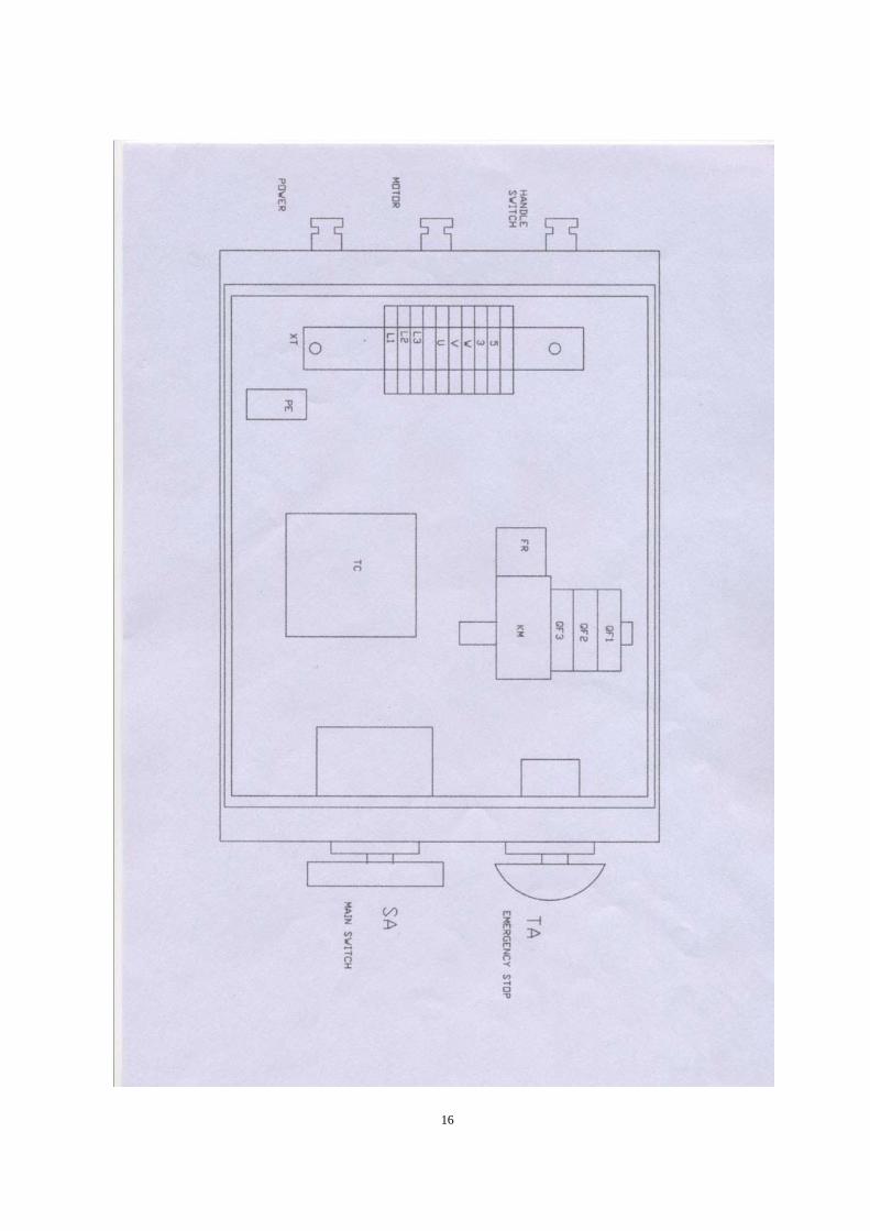
Have the electrical connections made by a qualified installer. Connect the machine in accordance with the electrical diagram applying to your machine.
Saw motor check whether the voltage indicated on the motor plate complies with the local main voltage. 5. Operation 5.1 Selection of the sawblade After years of research we recommend you to use only Timewinner saw blades. These saw blades have undergone a special heat treatment which guarantees high wear resistance. This means longer life before resharpening and less chance of cold welding. The quality of the saw blade is of great importance. The selection of the correct pitch depends on the material to be sawn. The selection of the correct pitch and rake angle is of great importance for the life of the sawblade.
5.2 Selection of pitch and tooth form
If the pitch is too small and the length of the cut too large, the cut material cannot be taken into the tooth cavity. The chip will get stuck in the tooth cavity, so that it is inactive in case of a second cut of the same tooth. This can cause the saw blade to jam and break. A pitch which is too large will cause the sawing tooth to hack as a result of which teeth can break free.
Hint :If a short, hard jerk is felt during sawing and the saw starts jolting, do not continue. In such cases it is almost certain that at one or more places a fine chip has

5
fused away at the flank of the saw tooth. This causes the saw to be slightly thicker at certain places. Remove the saw blade and remove the fused material with a fine-grained, high-grade saw file. Selection of the tooth form.
Besides a well selected pitch the following factors, too, are of great importance to facilitate the correct machining of the material (fig. 5.02):
Clearance angle ß and rake angle y of the tooth have been selected correctly in view of the material to be sawn. the principle is as follows.
Material Clearance angle Rake angle
Steel 8 22°
Stainless steel 6 15°
Non-ferrous 12 25°

6
Form of tooth cavity large enough compared to the pitch. A quick removal of the cut material and a correct depth and rounding of the tooth cavity are of the outmost importance. The tooth cavity must be large enough for the removed chips to be bend as long as the tooth is cutting. When the cutting tooth leaves the saw cut, the chip drops out of the tooth cavity.
The alternate saw (alternately bevelled edge) is often used for small pitches, especially up to 4 mm.
The precutting and finishing teeth are used for larger, solid material, usually from pitch 4 mm onwards. These teeth ensure that the chips are not all of the same length. If a chip were to be cut out the normal way, it would get hot, expand and become wider than the width of the cut. This would cause it to get stuck, as a result of which the chip could not be removed from the cut. The finishing tooth must be positioned 0.2 to 0.4 mm higher than the precutting tooth. The larger the pitch, the higher the precutting tooth must be placed as compared to the finishing tooth.
Consequently, only special machines are suitable for regrinding these teeth. When the blade has lost its cutting power, do not strain it. As a result the teeth may break off, which doubles the regrinding costs.
5.3 Sawing Capacity
For the maximum capacity in mm see the schedule for the profile figure/cross-cut in relationship with the miter angle. Write 90º we mean straight sawing.
5.4 Installing and replacing the saw blade
• Set the main switch in the off position. • Put the saw head in the upper position. • Open the guards • Release the socket head screw M8 of the saw spindle and remove the saw flange. • Remove the saw blade.

7
• Carefully clean the saw spindle and the saw flange. • Installing is done in reverse order. Pay attention to the direction of rotation of the sawblade. Make sure the saw blade is placed flush against the flange of the saw spindle. Check the setting of the sawing depth. Do not forget to close the safety guard. 5.5 Saw feed Manual saw feed The saw feed is determined by hand. The saw is lowered onto the material by means of the handle. Press the saw blade firmly onto the material, without using unnecessary force. When the saw pressure is too high this can cause the saw too break; when the saw pressure is too low, the saw will rapidly go blunt.
5.6 Every material has it’s own cutting speed. Below advice for some materials:
20 m/min > For steel alloy e.g. stainless steel 40 m/min > For normal steel 80 m/min > For non-ferrous materials
5.7 Clamping the material
It is of the outmost importance that the material is safely clamped in the material vice, so that it cannot tilt over or even move during sawing. In order to work efficiently, the material must always be clamped in such a way that the contact surface of the saw and the material is as small as possible. For instance, saw flat material on its thinnest side; this will considerable shorten sawing times. When very short pieces have to be sawn, and consequently only half of the material vice will be used, in order to prevent it from pulling out of alingment, a piece of material of equal thickness must be clamped in the other half of the vice. In this way the material is clamped tightly and evenly. Application of special vice jaws is recommendable for repetitive work

8
Mitre-sawing
Pull the clamping rod to the right and turn the sawing unit in the required miter position. The position can be read out on the scale division.Then fasten the clamping rod again. Do not use unnecessary force, a slight pull will suffice. Before clamping the material, check whether the saw is running completely clear between the jaws of the material vice. Place the steel vice jaws as closely as possible to the saw. 5.8 Cooling Cooling is of great importance to the life of the saw blade. After thorough investigation it has been established that the emulsifiable coolant absolutely prevents - among other things - the forming of so-called built-ups (the fusing of cut material to the tooth point flanks). This will prevent a jolting saw, which results in damage and breakage. Oils forms a lubricating film on the saw tooth points, so that, in case of increased saw feed, the high pressure between chip and tooth (chip surface of the saw tooth) will not lead to overheating of the saw. Here it is important that a correctly directed stream at the cutting edges of the saw ensures an ample supply of coolant for the removal of chips and the elimination of frictional heat.
5.9 Start/stop
• Make sure the material has been fed. • Check the sight-glass to see whether there is sufficient oil in the saw head. If necessary top up with BP GRXP 680 (ISO) through the vent hole in the handle. • Check the depth setting of the saw blade. • Check whether the vice jaws are suited for this material. • Adjust the material vice to the material. • Switch on the machine with the main switch. • Select the required speed. • Open the coolant cock on the safety guard (not in case of atomized lubrication). • Start machine with the switch on the pulling rod.
6 Maintenance
6.1 General
Clean the machine after it has been used and provide rust protection by applying a protective oil. Regularly remove the chips which gather underneath the vice jaws. In doing so use a thin, flat brush and NEVER an air jet.
The gears, the worm and the worm gear are subject to wear. The moment the replacement of these parts is due, depends on the usage. You can order a complete set, including instructions for disassembly and assembly from your

9
dealer. This kit is available from stock.
Regularly clean the coolant tank. This will considerable lengthen the life of the pump. Check the condition of the oil filter in the cooling circuit . If the filter is severely polluted, it needs to be cleaned or replaced. Check the oil level in the saw head every week. Check the oil level of the saw feed tank and refill if necessary. Check the oil bowl and the water separator every day. Refill the oil bowl with BP HLP 15 or a type of the same quality. Remove the water from the water separator of the air unit. With the PK-versions the glass can be screwed off.
6.2 Lubrication The gear box with the gear parts must be rinsed clean at least once per six months, depending on the use of the machine. Loosen the plug at the bottom of the saw head and drain the oil. Rinse the unit with petroleum and drain it thoroughly. Fill the unit with BP GRXP 680 (ISO) with 1.1 litre. Check the oil level on the sight-glass. If the saw head gets too hot while used continuously, the oil level in the saw head may be too high.
Once every three months the grease nipples of the pivots of the saw head must be greased with a universal grease. The 315 and 350-version has one grease nipple (fig. 6.03). The threaded spindle, the guide rods of the material vice and the guides of the machine bed must be oiled regularly. Use BP SHF 15 for this purpose.
6.3 Grinding the sawblades
It is only possible to work efficiently with a circular sawing machine when the saw blade
is reground in time. When the saw has lost its cutting ability, do not try to continue
sawing by pulling the handle harder, for this can cause teeth to break and the cost of
regrinding doubled.
Regrinding should only be done on special machines, constructed for this kind of work. Besides that it is advisable to check the saw optically in your own factory after they have been reground. In these optical checks special attention must be paid to the rake angle and the cleara nce angle
Fig. 6.03

10
Trouble shooting
Trouble Possible cause Remedy Excessive bouncing or breaking of the saw.
1. Speed an/or saw feed too high.
2. Teeth blunt, tooth cavities too small.
3. Wrong coolant Use Bewo Oil S
4. Saw jolts because chips remain in the saw cavity (cold-welding on the saw). 5. Saw installed incorrectly with respect to the direction of rotation.
Have the saw ground and the tooth cavity polished, so that the chips can easily slide through the tooth cavity. Turn the saw and check the teeth.
6. Worm and worm wheel worn out.
Replace.
Motor does not turn 1. Motor incorrectly connected.
2. Relays or motor defective.
3. Selector switch is in the OFF position
4. Thermal protection of motor defective
5. Fuses blown
6. Emergency stop button depressed
Cooling system does not work
1. Cock on saw guard in closed position.
2. Pump incorrectly connected.
3. Pump defective
4. Cooling tank empty
5. Suction pipe of cooling pump obstructed.

11
Survey of available saw blades Saw blades HSS DMO5, steam passivated
Material Dim. (mm) Pitch Article number
Steel 250x2x32 250x2x32
3/240 teeth 4/200 teeth
250x2x32 250x2x32 250x2x32
5/160 teeth 6/128 teeth 8/100 teeth
250x2x32 10/72 teeth 250x2x32 12/60 teeth Stainless steel 250x2x32
250x2x32 3/240 teeth 4/200 teeth
250x2x32 250x2x32
5/160 teeth 6/128 teeth
250x2x32 250x2x32 250x2x32
8/100 teeth 10/72 teeth 12/60 teeth
Steel 315x2,5x40
315x2,5x40 315x2,5x40
3/320 teeth 4/250 teeth 5/200 teeth
315x2,5x40 315x2,5x40
6/160 teeth 8/120 teeth
315x2,5x40 315x2,5x40
10/100 teeth 12/80 teeth
315x2,5x40 15/60 teeth Stainless steel 315x2,5x40
315x2,5x40 3/320 teeth 4/250 teeth
315x2,5x40 315x2,5x40
5/200 teeth 6/160 teeth
315x2,5x40 315x2,5x40 315x2,5x40
8/120 teeth 10/100 teeth 12/80 teeth
315x2,5x40 15/60 teeth Available on request:
.- Special saw blades for aluminium, brass and cupper Ordering spare parts : Direct your orders to your dealer only. In order to process your orders in the quickest way possible, we ask you to state the necessary information on your order including: Mains voltage, year of construction, description spare part and part No. , quantity ect..

12
Besides spare parts you can also order coolant and saw blades.
Parts drawing for CS250

13

14

15
16

17

18

19
Parts list for CS250/CS275 NO. Description Model Q'TY NO. Description Model Q'TY
1 Socket screw M8X20 2 45 Lock screw M8 1 1 Socket screw M6X16 1 46 Leading screw 1 2 Pulling arm 1 47 Spring 1 4 Spring ring 60 1 48 Bushing 1 5 Spring pin 6X20 1 49 Oil cup 6 1 6 Pulling arm 1 50 Lock sleeve 1 7 Safety guard 1 51 Lock screw M8X10 2 8 Hex screw M6X10 1 52 Lock handle 1 9 Fixed block 1 53 Thrust bearing 1 10 Water pipe 1 54 Sleeve 1 11 Water pipe 1 55 Handle 3 12 Hex screw M6X25 2 56 Handle seat 1 13 Washer 6 2 57 Big washer 8 1 14 Safety guard 1 58 Hex.screw M8X30 1 15 Hex screw M12X25 1 59 Lower vise 1 16 Press cover 1 60 Hex.screw M6X25 1 17 Pin 2 61 Shaft 1 18 Blade 1 62 Handle 1 19 Splined shaft 1 63 Screw M6 1 20 Fasten screw M8X8 1 64 Screw M8X16 2 21 Gear 1 65 Eccentri sleeve 1 22 Hex.screw M4X16 3 66 Eccentri shaft 1 23 Washer 4 3 67 Lock screw M6X12 1 24 Pump 1 68 Screw M10 3 25 Spring ring 9 1 69 Bolt M10X55 1 26 Bearing 1 70 Sping 1 27 Motor 1 71 Mat 1 28 Lock screw M8 4 72 Bolt M10X35 1 29 Stud bolt 4 73 Mat 1 30 Sealing ring 1 74 Bolt M10X30 2 31 Worm 1 75 Swivel arm 1 32 Screw M16 2 76 Spring pin M6X28 2 33 Bearing 1 77 Screw 1 34 Gear box 1 78 Hex.Screw M5X10 6 35 Handle lever 1 79 Washer 5 6 36 Screw M5X10 2 80 Water box 1 37 Handle switch M5X10 1 81 Base 1

20
38 Hex.screw M12X25 3 82 Sleeve 1 39 Mat 1 83 Hex.screw M8X35 1 40 Dovetail board 1 84 Lock handle 1 41 Bolt M20X1.5 1 85 Bolt M8X30 4 42 O-ring 1 86 Washer 8 4 43 Upper vise 1 87 Fixing bracket 1 44 Lock screw M8X20 1 88 Stand 1
Note: This manual is only for your reference. Owing to continuous improvement of the machines, Changes may be made at any time without obligation on notice.Please note the local voltage for operating this kind of electric machine