circular sump-oil drain
TRANSCRIPT

8/8/2019 Circular Sump-Oil Drain
http://slidepdf.com/reader/full/circular-sump-oil-drain 1/27
14.10.2010 R0 First Issue SDC SIVEN P SKL
DATE REV. NO. DESCRIPTION esigne Checked Approved
REVISIONS
AREVA T & D
CLIENT
MSETCLSS1B/SS2B PACAKAGE
PROJECT :
220/132/33KV SUBSTATION
JOB No.5257PN902/903
TOTAL NO. OF PAGES TITLE :
NAME SIGN DATE
Design of Circular Water Sump (Circular type)
DSGN SDC 31.05.10
CHKD IVEN 01.06.10
APPD SKL 07.06.10
REV.
DOC. N 5 2 5 7 P N 9 0 2 - C M D - C - S Y D - C A LR0
- 0 7 1 5
RELEASED FOR PRELIMINARY TENDER INFORMATION P APPROVAL CONSTRUCTION
T h i s d o c u m e n t i s t h e p r o p e r t y o
f A R E V A T & D I N D I A L T D a n d m u s
t n o t b e p a s s e d o n t o a n y t h i r d p e r s o n o r f i r m
n o t a u t h o r i s e d
b y u s , n o r b e c o p i e d / m a d e u s e o f i n f u l l o r p a r t b y s u c h p e r s o n o r f i r m
w i t h o u t o
u r p r i o r p e r m i s s i o n w r i t i n g

8/8/2019 Circular Sump-Oil Drain
http://slidepdf.com/reader/full/circular-sump-oil-drain 2/27

8/8/2019 Circular Sump-Oil Drain
http://slidepdf.com/reader/full/circular-sump-oil-drain 3/27

8/8/2019 Circular Sump-Oil Drain
http://slidepdf.com/reader/full/circular-sump-oil-drain 4/27

8/8/2019 Circular Sump-Oil Drain
http://slidepdf.com/reader/full/circular-sump-oil-drain 5/27
DESIGN OF CIRCULAR SUMP
8/8/2019 Circular Sump-Oil Drain
http://slidepdf.com/reader/full/circular-sump-oil-drain 6/27
AREVA T& D INDIA LIMITED
PROJECT 400/220/132 KV SUBSTATION, Nawada ( FARIDABAD)DOCUMENT NO. DATE
5257PN088-NWD-C-SYD-CAL-0715 14.10.2010
TITLE Design of Circular Water Sump (Circular type)DES CHKD APP
SKL ASL SKL
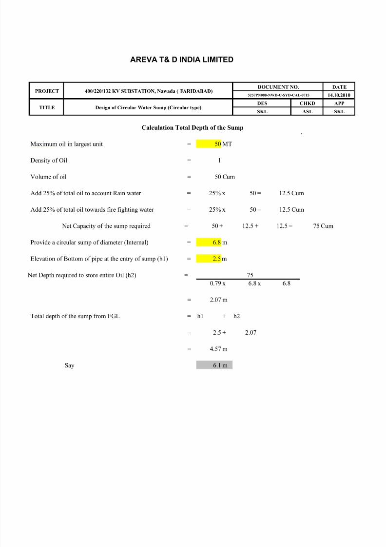
Calculation Total Depth of the Sump
`
Maximum oil in largest unit = 50 MT
Density of Oil = 1
Volume of oil = 50 Cum
Add 25% of total oil to account Rain water = 25% x 50 = 12.5 Cum
Add 25% of total oil towards fire fighting water = 25% x 50 = 12.5 Cum
Net Capacity of the sump required = 50 + 12.5 + 12.5 = 75 Cum
Provide a circular sump of diameter (Internal) = 6.8 m
Elevation of Bottom of pipe at the entry of sump (h1) = 2.5 m
Net Depth required to store entire Oil (h2) = 75
0.79 x 6.8 x 6.8
= 2.07 m
Total depth of the sump from FGL = h1 + h2
= 2.5 + 2.07
= 4.57 m
Say 6.1 m

8/8/2019 Circular Sump-Oil Drain
http://slidepdf.com/reader/full/circular-sump-oil-drain 7/27
Cap(m3 Dia Area Ht req FB Hoop Bars Vertical steel
20 4 12.57 1.59 0.15 1.74 1.75 0.15 0.15 0.15
25 4 12.57 1.99 0.15 2.14 2.14 0.15 0.15 0.15
30 4 12.57 2.39 0.15 2.54 2.54 0.2 0.2 0.240 5 19.63 2.04 0.15 2.19 2.19 0.2 0.2 0.2
50 5 19.63 2.55 0.15 2.70 2.70 0.2 0.2 0.2
Total clear ht
Roundu p
Wallthicknes
RaftThickness
TopSlabThickness

8/8/2019 Circular Sump-Oil Drain
http://slidepdf.com/reader/full/circular-sump-oil-drain 8/27
AREVA T& D INDIA LIMITED
PROJECT SS1B & SS2B PACKAGE MSETCLDOCUMENT NO. DATE
10/14/2010
TITLE Design Of circular water Tank DESIGNED CHECKED APPROVED
SDC SIVEN P SKL
DESIGN OF CIRCULAR SUMP
INPUT DATA
1) Diameter of well (D) = 4 m
2) Density of soil, ϒ = 1.76
3) Thickness of wall ( t ) at bottom = 0.25 m
4) = 30 °
5) Depth of well. (H) = 1.8 m
6) Density of Oil 1.00 t/m3
7) Density of Water 1.00 t/m3
8) Internal radius of the well r = 2 m
9) Maximum Permissible stress in direct Tension (Concrete) = 1.3 As per IS 3370 table 1 clause 3.3.1
10) Maximum Permissible stress in bending Tension (Concrete) 1.8 As per IS 3370 table 1 clause 3.3.1
11) Maximum Permissible stress in steel (as per IS 3370) = 150 N/mm2
12) Unit weight of Concrete = 2.5
13) Grade of concrete M 25 N/mm2
14) Grade of reinforcement steel Fe 415 N/mm2
Design coefficient
15) Permissible bending stress in conc 9 N/mm2
16) Modular Ratio (m) 10.37
17) Nutral axis depth factor (k) 0.38
18) Lever arm ( j ) 0.87
A Design of Wall
A well lining should be design considering the well as a special case of a thick cylinder,
the principle stresses developed are hoop stress & radial stress. Both hoop stress and radial stressdeveloped in awell are principl stresses and compressive in nature. The hoop stresses devloped is the
maximum and is twice the radial stress.Hence it is considered for the purpose of design.
Wall of the tank with fixed base will be subjected to bending moments also in addition to hoop tension
Moment shall be maximum at the base of the tank and for coefficient table 10 IS 3370
Asuume total thickness of the wall at the base = 150mm
Effective thickness of the wall 9 cm
As bending stress will reduce from bottom to top, thickness of the wall can be reduced as it moves up.
provide thickness of wall from top to 2.0 m below FGL. = 150 mm
provide thickness of wall from 2.01 to 4.0 m below FGL. = 150 mm
provide thickness of wall from 4.01 to 6.1 m below FGL. = 150 mm
H^2 = 3.06 = 5.1
D x t 4 x 0.15
Max Bending Moment = k1 * w * H^3 Kg-m/m
Refer Table 10 IS 3370 IV k1 = 0.01 (at Baseof the tank)
Max bending Moment = 0.01 x x 1000 x 5.36
= 42 Kgm/m
t/m3
Angle of repose (φ)
N/mm2
N/mm2
t/m3

8/8/2019 Circular Sump-Oil Drain
http://slidepdf.com/reader/full/circular-sump-oil-drain 9/27
AREVA T& D INDIA LIMITED
PROJECT SS1B & SS2B PACKAGE MSETCLDOCUMENT NO. DATE
10/14/2010
TITLE Design Of circular water Tank DESIGNED CHECKED APPROVED
SDC SIVEN P SKL
Max stress due to bending = 6 * M 6 * 4200 =
b x d^2 100 x 81
= 3.11 Kg/sqcm < 18 O.K.
P P
P
Hoop stress , = P*D*k2
2
for k2 refer table 9 of IS 3370 part IV
When Tank is empty P shall be due to earth pressure
P = 0.33 x 0 x 175
= 0.1 Kg/Cm2
When Tank is Full and there is no Soil outside (Density of Water is considered for calculation purpose)
P = 1 x 0 x 175.0= 0.18 Kg/Cm2
Maximum Pressure = 0.18K g/Cm2
k2 for H^2/Dt of 14 = 0.477
Hoop tension (T) at Base = 0.18 x 400 x 0.477
2
= 16.7 Kg/cm
Max direct tension in conc (T/thk) = 16.7
9
= 1.86 Kg/sq.cm < 13 O.K.
Check for Acutal direct tension + Actual bending stress < 1
Per. Direct tension per. Bending stress
1.86 + 3.11 = 0.32 < 1 O.K.
13 18
Reinforcement Steel
στmax
r r1

8/8/2019 Circular Sump-Oil Drain
http://slidepdf.com/reader/full/circular-sump-oil-drain 10/27
AREVA T& D INDIA LIMITED
PROJECT SS1B & SS2B PACKAGE MSETCLDOCUMENT NO. DATE
10/14/2010
TITLE Design Of circular water Tank DESIGNED CHECKED APPROVED
SDC SIVEN P SKL
1) Area of hoop reinforcement = 16.7 x 1001500
= 1.2 Cm2/ meter (both faces)
At each face 60 mm2
Provide reinf. both way @ 230 m c/c of dia 8 mm
Actual area of steel provided = 2.18 cm2 > 0.6 O.K.
2) Vertical reinforcement steel Ast' 420000
Ast = = 150 x 0.87 x 90
= 35.67 sq. mm
Minimum Reinforcement required = 0.3% on both the faces and hence 0.15% on each face.
= 0.15 x 9 = 1.35 cm2 per meter
Provide reinf. both way @ 210 mm c/c of dia 8 mm
Actual area of steel provided = 2.39 cm2 > 1.35 O.K. (On both the faces.)
B. Design of Base slab
Provide same thickness as of wall 15 cm
provide minimum reinforcement steel 0.24% on both faces
= 0.24 x 15 x 100100
= 3.6 cm2
Area of steel required at each face = 1.8 cm2
Provide bottom reinf. both way @ 193 mm c/c of dia 8 mm
Actual area of steel provided = 2.60 cm2 > 1.8 O.K. (On both faces and bothways)
B. Design of Roof slab
Assume thickness of roof slab = 15 cm
Load Calculations
1) Self weght of slab = 2500 x 0.15 = 375 Kgs
2) Plaster and finishes = 2400 x 0.015 = 36 Kgs
3) Live Load = = 350 Kgs
Total 761 Kgs
Say 7.5 KN
Maximum Radial Moment = 1 x W x r^2
16
B.M./(σst*j*d)
8/8/2019 Circular Sump-Oil Drain
http://slidepdf.com/reader/full/circular-sump-oil-drain 11/27
AREVA T& D INDIA LIMITED
PROJECT SS1B & SS2B PACKAGE MSETCLDOCUMENT NO. DATE
10/14/2010
TITLE Design Of circular water Tank DESIGNED CHECKED APPROVED
SDC SIVEN P SKL
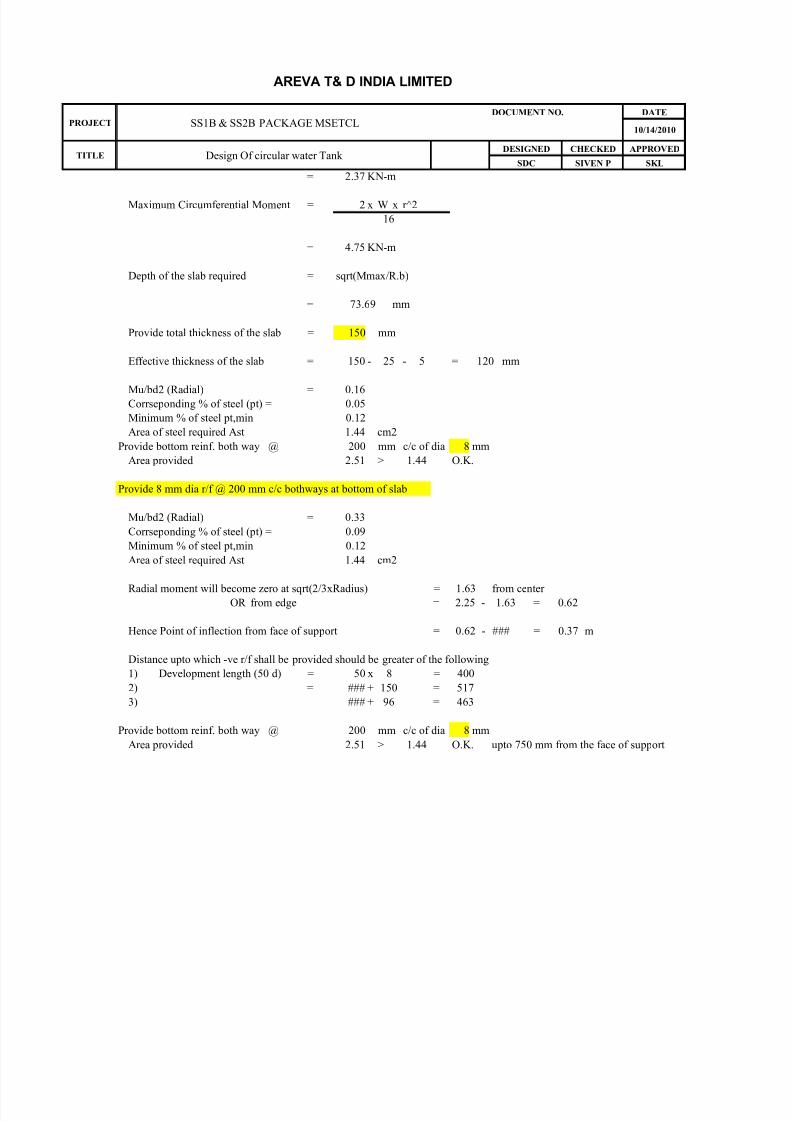
= 2.37 KN-m
Maximum Circumferential Moment = 2 x W x r^2
16
= 4.75 KN-m
Depth of the slab required = sqrt(Mmax/R.b)
= 73.69 mm
Provide total thickness of the slab = 150 mm
Effective thickness of the slab = 150 - 25 - 5 = 120 mm
Mu/bd2 (Radial) = 0.16Corrseponding % of steel (pt) = 0.05
Minimum % of steel pt,min 0.12
Area of steel required Ast 1.44 cm2
Provide bottom reinf. both way @ 200 mm c/c of dia 8 mm
Area provided 2.51 > 1.44 O.K.
Provide 8 mm dia r/f @ 200 mm c/c bothways at bottom of slab
Mu/bd2 (Radial) = 0.33
Corrseponding % of steel (pt) = 0.09
Minimum % of steel pt,min 0.12
Area of steel required Ast 1.44 cm2
Radial moment will become zero at sqrt(2/3xRadius) = 1.63 from center OR from edge = 2.25 - 1.63 = 0.62
Hence Point of inflection from face of support = 0.62 - ### = 0.37 m
Distance upto which -ve r/f shall be provided should be greater of the following
1) Development length (50 d) = 50 x 8 = 400
2) = ### + 150 = 517
3) ### + 96 = 463
Provide bottom reinf. both way @ 200 mm c/c of dia 8 mm
Area provided 2.51 > 1.44 O.K. upto 750 mm from the face of support

8/8/2019 Circular Sump-Oil Drain
http://slidepdf.com/reader/full/circular-sump-oil-drain 12/27
AREVA T& D INDIA LIMITED
PROJECT /220/132 KV SUBSTATION, Pimpalgaon (Nashik)DOCUMENT NO. DATE
10/14/2010
TITLE Design Of circular water Tank DESIGNED CHECKED APPROVED
SDC SIVEN P SKL
DESIGN OF CIRCULAR SUMP
INPUT DATA
1) Diameter of well (D) = 4 m
2) Density of soil, ϒ = 1.76
3) Thickness of wall ( t ) at bottom = 0.25 m
4) = 30 °
5) Depth of well. (H) = 2.2 m
7) Density of Water 1.00 t/m3
8) Internal radius of the well r = 2 m
9) Maximum Permissible stress in direct Tension (Concrete) = 1.3 As per IS 3370 table 1 clause 3.3.1
10) Maximum Permissible stress in bending Tension (Concrete) 1.8 As per IS 3370 table 1 clause 3.3.1
11) Maximum Permissible stress in steel (as per IS 3370) = 150 N/mm2
12) Unit weight of Concrete = 2.5
13) Grade of concrete M 25 N/mm2
14) Grade of reinforcement steel Fe 415 N/mm2
Design coefficient
15) Permissible bending stress in conc 9 N/mm2
16) Modular Ratio (m) 10.37
17) Nutral axis depth factor (k) 0.38
18) Lever arm ( j ) 0.87
A Design of Wall
A well lining should be design considering the well as a special case of a thick cylinder,
the principle stresses developed are hoop stress & radial stress. Both hoop stress and radial stress
developed in awell are principl stresses and compressive in nature. The hoop stresses devloped is themaximum and is twice the radial stress.Hence it is considered for the purpose of design.
Wall of the tank with fixed base will be subjected to bending moments also in addition to hoop tension
Moment shall be maximum at the base of the tank and for coefficient table 10 IS 3370
Asuume total thickness of the wall at the base = 150mm
Effective thickness of the wall 9 cm
As bending stress will reduce from bottom to top, thickness of the wall can be reduced as it moves up.
provide thickness of wall from top to 2.0 m below FGL. = 150 mm
provide thickness of wall from 2.01 to 4.0 m below FGL. = 150 mm
provide thickness of wall from 4.01 to 6.1 m below FGL. = 150 mm
H^2 = 4.84 = 8.07
D x t 4 x 0.15
Max Bending Moment = k1 * w * H^3 Kg-m/m
Refer Table 10 IS 3370 IV k1 = 0.01 (at Baseof the tank)
Max bending Moment = 0.01 x x 1000 x 10.65
= 156 Kgm/m
Max stress due to bending = 6 * M 6 * 15600 =
t/m3
Angle of repose (φ)
N/mm2
N/mm2
t/m3

8/8/2019 Circular Sump-Oil Drain
http://slidepdf.com/reader/full/circular-sump-oil-drain 13/27
AREVA T& D INDIA LIMITED
PROJECT /220/132 KV SUBSTATION, Pimpalgaon (Nashik)DOCUMENT NO. DATE
10/14/2010
TITLE Design Of circular water Tank DESIGNED CHECKED APPROVED
SDC SIVEN P SKL
b x d^2 100 x 81
= 11.56 Kg/sqcm < 18 O.K.
P
P P
PHoop stress , = P*D*k2
2
for k2 refer table 9 of IS 3370 part IV
When Tank is empty P shall be due to earth pressure
P = 0.33 x 0 x 220
= 0.13 Kg/Cm2
When Tank is Full and there is no Soil outside (Density of Water is considered for calculation purpose)
P = 1 x 0 x 220.0
= 0.22 Kg/Cm2
Maximum Pressure = 0.22K g/Cm2
k2 for H^2/Dt of 14 = 0.575
Hoop tension (T) at Base = 0.22 x 400 x 0.575
2
= 25.3 Kg/cm
Max direct tension in conc (T/thk) = 25.3
9
= 2.81 Kg/sq.cm < 13 O.K.
Check for Acutal direct tension + Actual bending stress < 1
Per. Direct tension per. Bending stress
2.81 + 11.56 = 0.86 < 1 O.K.
13 18
Reinforcement Steel
στmax
r r1

8/8/2019 Circular Sump-Oil Drain
http://slidepdf.com/reader/full/circular-sump-oil-drain 14/27
AREVA T& D INDIA LIMITED
PROJECT /220/132 KV SUBSTATION, Pimpalgaon (Nashik)DOCUMENT NO. DATE
10/14/2010
TITLE Design Of circular water Tank DESIGNED CHECKED APPROVED
SDC SIVEN P SKL
1) Area of hoop reinforcement = 25.3 x 100
1500= 1.7 Cm2/ meter (both faces)
At each face 85 mm2
Provide reinf. both way @ 230 m c/c of dia 8 mm
Actual area of steel provided = 2.18 cm2 > 0.85 O.K.
2) Vertical reinforcement steel Ast' 1560000
Ast = = 150 x 0.87 x 90
= 132.5 sq. mm
Minimum Reinforcement required = 0.3% on both the faces and hence 0.15% on each face.
= 0.15 x 9 = 1.35 cm2 per meter
Provide reinf. both way @ 210 mm c/c of dia 8 mm
Actual area of steel provided = 2.39 cm2 > 1.35 O.K. (On both the faces.)
B. Design of Base slab
Provide same thickness as of wall 15 cm
provide minimum reinforcement steel 0.24% on both faces
= 0.24 x 15 x 100
100= 3.6 cm2
Area of steel required at each face = 1.8 cm2
Provide bottom reinf. both way @ 193 mm c/c of dia 8 mm
Actual area of steel provided = 2.60 cm2 > 1.8 O.K. (On both faces and bothways)
B. Design of Roof slab
Assume thickness of roof slab = 15 cm
Load Calculations
1) Self weght of slab = 2500 x 0.15 = 375 Kgs
2) Plaster and finishes = 2400 x 0.015 = 36 Kgs
3) Live Load = = 350 Kgs
Total 761 Kgs
Say 7.5 KN
Maximum Radial Moment = 1 x W x r^2
16
= 2.37 KN-m
B.M./(σst*j*d)

8/8/2019 Circular Sump-Oil Drain
http://slidepdf.com/reader/full/circular-sump-oil-drain 15/27
AREVA T& D INDIA LIMITED
PROJECT /220/132 KV SUBSTATION, Pimpalgaon (Nashik)DOCUMENT NO. DATE
10/14/2010
TITLE Design Of circular water Tank DESIGNED CHECKED APPROVED
SDC SIVEN P SKL
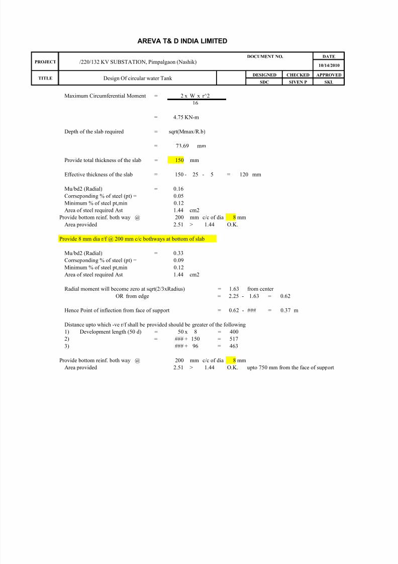
Maximum Circumferential Moment = 2 x W x r^216
= 4.75 KN-m
Depth of the slab required = sqrt(Mmax/R.b)
= 73.69 mm
Provide total thickness of the slab = 150 mm
Effective thickness of the slab = 150 - 25 - 5 = 120 mm
Mu/bd2 (Radial) = 0.16
Corrseponding % of steel (pt) = 0.05Minimum % of steel pt,min 0.12
Area of steel required Ast 1.44 cm2
Provide bottom reinf. both way @ 200 mm c/c of dia 8 mm
Area provided 2.51 > 1.44 O.K.
Provide 8 mm dia r/f @ 200 mm c/c bothways at bottom of slab
Mu/bd2 (Radial) = 0.33
Corrseponding % of steel (pt) = 0.09
Minimum % of steel pt,min 0.12
Area of steel required Ast 1.44 cm2
Radial moment will become zero at sqrt(2/3xRadius) = 1.63 from center
OR from edge = 2.25 - 1.63 = 0.62
Hence Point of inflection from face of support = 0.62 - ### = 0.37 m
Distance upto which -ve r/f shall be provided should be greater of the following
1) Development length (50 d) = 50 x 8 = 400
2) = ### + 150 = 517
3) ### + 96 = 463
Provide bottom reinf. both way @ 200 mm c/c of dia 8 mm
Area provided 2.51 > 1.44 O.K. upto 750 mm from the face of support

8/8/2019 Circular Sump-Oil Drain
http://slidepdf.com/reader/full/circular-sump-oil-drain 16/27
AREVA T& D INDIA LIMITED
PROJECT /220/132 KV SUBSTATION, Pimpalgaon (Nashik)DOCUMENT NO. DATE
10/14/2010
TITLE Design Of circular water Tank DESIGNED CHECKED APPROVED
SDC SIVEN P SKL
DESIGN OF CIRCULAR SUMP
INPUT DATA
1) Diameter of well (D) = 4 m
2) Density of soil, ϒ = 1.76
3) Thickness of wall ( t ) at bottom = 0.25 m
4) = 30 °
5) Depth of well. (H) = 2.6 m
7) Density of Water 1.00 t/m3
8) Internal radius of the well r = 2 m
9) Maximum Permissible stress in direct Tension (Concrete) = 1.3 As per IS 3370 table 1 clause 3.3.1
10) Maximum Permissible stress in bending Tension (Concrete) 1.8 As per IS 3370 table 1 clause 3.3.1
11) Maximum Permissible stress in steel (as per IS 3370) = 150 N/mm2
12) Unit weight of Concrete = 2.5
13) Grade of concrete M 25 N/mm2
14) Grade of reinforcement steel Fe 415 N/mm2
Design coefficient
15) Permissible bending stress in conc 9 N/mm2
16) Modular Ratio (m) 10.37
17) Nutral axis depth factor (k) 0.38
18) Lever arm ( j ) 0.87
A Design of Wall
A well lining should be design considering the well as a special case of a thick cylinder,
the principle stresses developed are hoop stress & radial stress. Both hoop stress and radial stress
developed in awell are principl stresses and compressive in nature. The hoop stresses devloped is themaximum and is twice the radial stress.Hence it is considered for the purpose of design.
Wall of the tank with fixed base will be subjected to bending moments also in addition to hoop tension
Moment shall be maximum at the base of the tank and for coefficient table 10 IS 3370
Asuume total thickness of the wall at the base = 200mm
Effective thickness of the wall 14 cm
As bending stress will reduce from bottom to top, thickness of the wall can be reduced as it moves up.
provide thickness of wall from top to 2.0 m below FGL. = 200 mm
provide thickness of wall from 2.01 to 4.0 m below FGL. = 200 mm
provide thickness of wall from 4.01 to 6.1 m below FGL. = 200 mm
H^2 = 6.76 = 8.45
D x t 4 x 0.20
Max Bending Moment = k1 * w * H^3 Kg-m/m
Refer Table 10 IS 3370 IV k1 = 0.01 (at Baseof the tank)
Max bending Moment = 0.01 x x 1000 x 17.58
= 257 Kgm/m
Max stress due to bending = 6 * M 6 * 25700 =
t/m3
Angle of repose (φ)
N/mm2
N/mm2
t/m3

8/8/2019 Circular Sump-Oil Drain
http://slidepdf.com/reader/full/circular-sump-oil-drain 17/27
AREVA T& D INDIA LIMITED
PROJECT /220/132 KV SUBSTATION, Pimpalgaon (Nashik)DOCUMENT NO. DATE
10/14/2010
TITLE Design Of circular water Tank DESIGNED CHECKED APPROVED
SDC SIVEN P SKL
b x d^2 100 x 196
= 7.87 Kg/sqcm < 18 O.K.
P
P P
PHoop stress , = P*D*k2
2
for k2 refer table 9 of IS 3370 part IV
When Tank is empty P shall be due to earth pressure
P = 0.33 x 0 x 260
= 0.15 Kg/Cm2
When Tank is Full and there is no Soil outside (Density of Water is considered for calculation purpose)
P = 1 x 0 x 260.0
= 0.26 Kg/Cm2
Maximum Pressure = 0.26K g/Cm2
k2 for H^2/Dt of 14 = 0.608
Hoop tension (T) at Base = 0.26 x 400 x 0.608
2
= 31.62 Kg/cm
Max direct tension in conc (T/thk) = 31.62
14
= 2.26 Kg/sq.cm < 13 O.K.
Check for Acutal direct tension + Actual bending stress < 1
Per. Direct tension per. Bending stress
2.26 + 7.87 = 0.61 < 1 O.K.
13 18
Reinforcement Steel
στmax
r r1

8/8/2019 Circular Sump-Oil Drain
http://slidepdf.com/reader/full/circular-sump-oil-drain 18/27
AREVA T& D INDIA LIMITED
PROJECT /220/132 KV SUBSTATION, Pimpalgaon (Nashik)DOCUMENT NO. DATE
10/14/2010
TITLE Design Of circular water Tank DESIGNED CHECKED APPROVED
SDC SIVEN P SKL
1) Area of hoop reinforcement = 31.62x 100
1500= 2.2 Cm2/ meter (both faces)
At each face 110 mm2
Provide reinf. both way @ 230 m c/c of dia 8 mm
Actual area of steel provided = 2.18 cm2 > 1.1 O.K.
2) Vertical reinforcement steel Ast' 2570000
Ast = = 150 x 0.87 x 140
= ### sq. mm
Minimum Reinforcement required = 0.3% on both the faces and hence 0.15% on each face.
= 0.15 x 14 = 2.1 cm2 per meter
Provide reinf. both way @ 210 mm c/c of dia 8 mm
Actual area of steel provided = 2.39 cm2 > 2.1 O.K. (On both the faces.)
B. Design of Base slab
Provide same thickness as of wall 20 cm
provide minimum reinforcement steel 0.24% on both faces
= 0.24 x 20 x 100
100= 4.8 cm2
Area of steel required at each face = 2.4 cm2
Provide bottom reinf. both way @ 193 mm c/c of dia 8 mm
Actual area of steel provided = 2.60 cm2 > 2.4 O.K. (On both faces and bothways)
B. Design of Roof slab
Assume thickness of roof slab = 15 cm
Load Calculations
1) Self weght of slab = 2500 x 0.15 = 375 Kgs
2) Plaster and finishes = 2400 x 0.015 = 36 Kgs
3) Live Load = = 350 Kgs
Total 761 Kgs
Say 7.5 KN
Maximum Radial Moment = 1 x W x r^2
16
= 2.37 KN-m
B.M./(σst*j*d)
8/8/2019 Circular Sump-Oil Drain
http://slidepdf.com/reader/full/circular-sump-oil-drain 19/27
AREVA T& D INDIA LIMITED
PROJECT /220/132 KV SUBSTATION, Pimpalgaon (Nashik)DOCUMENT NO. DATE
10/14/2010
TITLE Design Of circular water Tank DESIGNED CHECKED APPROVED
SDC SIVEN P SKL
Maximum Circumferential Moment = 2 x W x r^216
= 4.75 KN-m
Depth of the slab required = sqrt(Mmax/R.b)
= 73.69 mm
Provide total thickness of the slab = 150 mm
Effective thickness of the slab = 150 - 25 - 5 = 120 mm
Mu/bd2 (Radial) = 0.16
Corrseponding % of steel (pt) = 0.05Minimum % of steel pt,min 0.12
Area of steel required Ast 1.44 cm2
Provide bottom reinf. both way @ 200 mm c/c of dia 8 mm
Area provided 2.51 > 1.44 O.K.
Provide 8 mm dia r/f @ 200 mm c/c bothways at bottom of slab
Mu/bd2 (Radial) = 0.33
Corrseponding % of steel (pt) = 0.09
Minimum % of steel pt,min 0.12
Area of steel required Ast 1.44 cm2
Radial moment will become zero at sqrt(2/3xRadius) = 1.63 from center
OR from edge = 2.25 - 1.63 = 0.62
Hence Point of inflection from face of support = 0.62 - ### = 0.37 m
Distance upto which -ve r/f shall be provided should be greater of the following
1) Development length (50 d) = 50 x 8 = 400
2) = ### + 150 = 517
3) ### + 96 = 463
Provide bottom reinf. both way @ 200 mm c/c of dia 8 mm
Area provided 2.51 > 1.44 O.K. upto 750 mm from the face of support

8/8/2019 Circular Sump-Oil Drain
http://slidepdf.com/reader/full/circular-sump-oil-drain 20/27
AREVA T& D INDIA LIMITED
PROJECT /220/132 KV SUBSTATION, Pimpalgaon (Nashik)DOCUMENT NO. DATE
10/14/2010
TITLE Design Of circular water Tank DESIGNED CHECKED APPROVED
SDC SIVEN P SKL
DESIGN OF CIRCULAR SUMP
INPUT DATA
1) Diameter of well (D) = 5 m
2) Density of soil, ϒ = 1.76
3) Thickness of wall ( t ) at bottom = 0.25 m
4) = 30 °
5) Depth of well. (H) = 2.2 m
7) Density of Water 1.00 t/m3
8) Internal radius of the well r = 2.5 m
9) Maximum Permissible stress in direct Tension (Concrete) = 1.3 As per IS 3370 table 1 clause 3.3.1
10) Maximum Permissible stress in bending Tension (Concrete) 1.8 As per IS 3370 table 1 clause 3.3.1
11) Maximum Permissible stress in steel (as per IS 3370) = 150 N/mm2
12) Unit weight of Concrete = 2.5
13) Grade of concrete M 25 N/mm2
14) Grade of reinforcement steel Fe 415 N/mm2
Design coefficient
15) Permissible bending stress in conc 9 N/mm2
16) Modular Ratio (m) 10.37
17) Nutral axis depth factor (k) 0.38
18) Lever arm ( j ) 0.87
A Design of Wall
A well lining should be design considering the well as a special case of a thick cylinder,
the principle stresses developed are hoop stress & radial stress. Both hoop stress and radial stress
developed in awell are principl stresses and compressive in nature. The hoop stresses devloped is themaximum and is twice the radial stress.Hence it is considered for the purpose of design.
Wall of the tank with fixed base will be subjected to bending moments also in addition to hoop tension
Moment shall be maximum at the base of the tank and for coefficient table 10 IS 3370
Asuume total thickness of the wall at the base = 200mm
Effective thickness of the wall 14 cm
As bending stress will reduce from bottom to top, thickness of the wall can be reduced as it moves up.
provide thickness of wall from top to 2.0 m below FGL. = 200 mm
provide thickness of wall from 2.01 to 4.0 m below FGL. = 200 mm
provide thickness of wall from 4.01 to 6.1 m below FGL. = 200 mm
H^2 = 4.84 = 4.84
D x t 5 x 0.20
Max Bending Moment = k1 * w * H^3 Kg-m/m
Refer Table 10 IS 3370 IV k1 = 0.02 (at Baseof the tank)
Max bending Moment = 0.02 x x 1000 x 10.65
= 235 Kgm/m
Max stress due to bending = 6 * M 6 * 23500 =
t/m3
Angle of repose (φ)
N/mm2
N/mm2
t/m3

8/8/2019 Circular Sump-Oil Drain
http://slidepdf.com/reader/full/circular-sump-oil-drain 21/27
AREVA T& D INDIA LIMITED
PROJECT /220/132 KV SUBSTATION, Pimpalgaon (Nashik)DOCUMENT NO. DATE
10/14/2010
TITLE Design Of circular water Tank DESIGNED CHECKED APPROVED
SDC SIVEN P SKL
b x d^2 100 x 196
= 7.19 Kg/sqcm < 18 O.K.
P
P P
PHoop stress , = P*D*k2
2
for k2 refer table 9 of IS 3370 part IV
When Tank is empty P shall be due to earth pressure
P = 0.33 x 0 x 220
= 0.13 Kg/Cm2
When Tank is Full and there is no Soil outside (Density of Water is considered for calculation purpose)
P = 1 x 0 x 220.0
= 0.22 Kg/Cm2
Maximum Pressure = 0.22K g/Cm2
k2 for H^2/Dt of 14 = 0.477
Hoop tension (T) at Base = 0.22 x 500 x 0.477
2
= 26.24 Kg/cm
Max direct tension in conc (T/thk) = 26.24
14
= 1.87 Kg/sq.cm < 13 O.K.
Check for Acutal direct tension + Actual bending stress < 1
Per. Direct tension per. Bending stress
1.87 + 7.19 = 0.54 < 1 O.K.
13 18
Reinforcement Steel
στmax
r r1

8/8/2019 Circular Sump-Oil Drain
http://slidepdf.com/reader/full/circular-sump-oil-drain 22/27
AREVA T& D INDIA LIMITED
PROJECT /220/132 KV SUBSTATION, Pimpalgaon (Nashik)DOCUMENT NO. DATE
10/14/2010
TITLE Design Of circular water Tank DESIGNED CHECKED APPROVED
SDC SIVEN P SKL
1) Area of hoop reinforcement = 26.24x 100
1500= 1.8 Cm2/ meter (both faces)
At each face 90 mm2
Provide reinf. both way @ 230 m c/c of dia 8 mm
Actual area of steel provided = 2.18 cm2 > 0.9 O.K.
2) Vertical reinforcement steel Ast' 2350000
Ast = = 150 x 0.87 x 140
= ### sq. mm
Minimum Reinforcement required = 0.3% on both the faces and hence 0.15% on each face.
= 0.15 x 14 = 2.1 cm2 per meter
Provide reinf. both way @ 210 mm c/c of dia 8 mm
Actual area of steel provided = 2.39 cm2 > 2.1 O.K. (On both the faces.)
B. Design of Base slab
Provide same thickness as of wall 20 cm
provide minimum reinforcement steel 0.24% on both faces
= 0.24 x 20 x 100
100= 4.8 cm2
Area of steel required at each face = 2.4 cm2
Provide bottom reinf. both way @ 193 mm c/c of dia 8 mm
Actual area of steel provided = 2.60 cm2 > 2.4 O.K. (On both faces and bothways)
B. Design of Roof slab
Assume thickness of roof slab = 15 cm
Load Calculations
1) Self weght of slab = 2500 x 0.15 = 375 Kgs
2) Plaster and finishes = 2400 x 0.015 = 36 Kgs
3) Live Load = = 350 Kgs
Total 761 Kgs
Say 7.5 KN
Maximum Radial Moment = 1 x W x r^2
16
= 3.54 KN-m
B.M./(σst*j*d)

8/8/2019 Circular Sump-Oil Drain
http://slidepdf.com/reader/full/circular-sump-oil-drain 23/27
AREVA T& D INDIA LIMITED
PROJECT /220/132 KV SUBSTATION, Pimpalgaon (Nashik)DOCUMENT NO. DATE
10/14/2010
TITLE Design Of circular water Tank DESIGNED CHECKED APPROVED
SDC SIVEN P SKL
Maximum Circumferential Moment = 2 x W x r^216
= 7.09 KN-m
Depth of the slab required = sqrt(Mmax/R.b)
= 90.07 mm
Provide total thickness of the slab = 150 mm
Effective thickness of the slab = 150 - 25 - 5 = 120 mm
Mu/bd2 (Radial) = 0.25
Corrseponding % of steel (pt) = 0.07Minimum % of steel pt,min 0.12
Area of steel required Ast 1.44 cm2
Provide bottom reinf. both way @ 200 mm c/c of dia 8 mm
Area provided 2.51 > 1.44 O.K.
Provide 8 mm dia r/f @ 200 mm c/c bothways at bottom of slab
Mu/bd2 (Radial) = 0.49
Corrseponding % of steel (pt) = 0.14
Minimum % of steel pt,min 0.12
Area of steel required Ast 1.68 cm2
Radial moment will become zero at sqrt(2/3xRadius) = 2.04 from center
OR from edge = 2.75 - 2.04 = 0.71
Hence Point of inflection from face of support = 0.71 - ### = 0.46 m
Distance upto which -ve r/f shall be provided should be greater of the following
1) Development length (50 d) = 50 x 8 = 400
2) = ### + 150 = 609
3) ### + 96 = 555
Provide bottom reinf. both way @ 200 mm c/c of dia 8 mm
Area provided 2.51 > 1.68 O.K. upto 750 mm from the face of support

8/8/2019 Circular Sump-Oil Drain
http://slidepdf.com/reader/full/circular-sump-oil-drain 24/27
AREVA T& D INDIA LIMITED
PROJECT /220/132 KV SUBSTATION, Pimpalgaon (Nashik)DOCUMENT NO. DATE
10/14/2010
TITLE Design Of circular water Tank DESIGNED CHECKED APPROVED
SDC SIVEN P SKL
DESIGN OF CIRCULAR SUMP
INPUT DATA
1) Diameter of well (D) = 5 m
2) Density of soil, ϒ = 1.76
3) Thickness of wall ( t ) at bottom = 0.25 m
4) = 30 °
5) Depth of well. (H) = 2.7 m
7) Density of Water 1.00 t/m3
8) Internal radius of the well r = 2.5 m
9) Maximum Permissible stress in direct Tension (Concrete) = 1.3 As per IS 3370 table 1 clause 3.3.1
10) Maximum Permissible stress in bending Tension (Concrete) 1.8 As per IS 3370 table 1 clause 3.3.1
11) Maximum Permissible stress in steel (as per IS 3370) = 150 N/mm2
12) Unit weight of Concrete = 2.5
13) Grade of concrete M 25 N/mm2
14) Grade of reinforcement steel Fe 415 N/mm2
Design coefficient
15) Permissible bending stress in conc 9 N/mm2
16) Modular Ratio (m) 10.37
17) Nutral axis depth factor (k) 0.38
18) Lever arm ( j ) 0.87
A Design of Wall
A well lining should be design considering the well as a special case of a thick cylinder,
the principle stresses developed are hoop stress & radial stress. Both hoop stress and radial stress
developed in awell are principl stresses and compressive in nature. The hoop stresses devloped is themaximum and is twice the radial stress.Hence it is considered for the purpose of design.
Wall of the tank with fixed base will be subjected to bending moments also in addition to hoop tension
Moment shall be maximum at the base of the tank and for coefficient table 10 IS 3370
Asuume total thickness of the wall at the base = 200mm
Effective thickness of the wall 14 cm
As bending stress will reduce from bottom to top, thickness of the wall can be reduced as it moves up.
provide thickness of wall from top to 2.0 m below FGL. = 200 mm
provide thickness of wall from 2.01 to 4.0 m below FGL. = 200 mm
provide thickness of wall from 4.01 to 6.1 m below FGL. = 200 mm
H^2 = 7.29 = 7.29
D x t 5 x 0.20
Max Bending Moment = k1 * w * H^3 Kg-m/m
Refer Table 10 IS 3370 IV k1 = 0.02 (at Baseof the tank)
Max bending Moment = 0.02 x x 1000 x 19.68
= 369 Kgm/m
Max stress due to bending = 6 * M 6 * 36900 =
t/m3
Angle of repose (φ)
N/mm2
N/mm2
t/m3

8/8/2019 Circular Sump-Oil Drain
http://slidepdf.com/reader/full/circular-sump-oil-drain 25/27
AREVA T& D INDIA LIMITED
PROJECT /220/132 KV SUBSTATION, Pimpalgaon (Nashik)DOCUMENT NO. DATE
10/14/2010
TITLE Design Of circular water Tank DESIGNED CHECKED APPROVED
SDC SIVEN P SKL
b x d^2 100 x 196
= 11.3 Kg/sqcm < 18 O.K.
P
P P
PHoop stress , = P*D*k2
2
for k2 refer table 9 of IS 3370 part IV
When Tank is empty P shall be due to earth pressure
P = 0.33 x 0 x 270
= 0.16 Kg/Cm2
When Tank is Full and there is no Soil outside (Density of Water is considered for calculation purpose)
P = 1 x 0 x 270.0
= 0.27 Kg/Cm2
Maximum Pressure = 0.27K g/Cm2
k2 for H^2/Dt of 14 = 0.575
Hoop tension (T) at Base = 0.27 x 500 x 0.575
2
= 38.81 Kg/cm
Max direct tension in conc (T/thk) = 38.81
14
= 2.77 Kg/sq.cm < 13 O.K.
Check for Acutal direct tension + Actual bending stress < 1
Per. Direct tension per. Bending stress
2.77 + 11.3 = 0.84 < 1 O.K.
13 18
Reinforcement Steel
στmax
r r1

8/8/2019 Circular Sump-Oil Drain
http://slidepdf.com/reader/full/circular-sump-oil-drain 26/27
AREVA T& D INDIA LIMITED
PROJECT /220/132 KV SUBSTATION, Pimpalgaon (Nashik)DOCUMENT NO. DATE
10/14/2010
TITLE Design Of circular water Tank DESIGNED CHECKED APPROVED
SDC SIVEN P SKL
1) Area of hoop reinforcement = 38.81x 100
1500= 2.6 Cm2/ meter (both faces)
At each face 130 mm2
Provide reinf. both way @ 230 m c/c of dia 8 mm
Actual area of steel provided = 2.18 cm2 > 1.3 O.K.
2) Vertical reinforcement steel Ast' 3690000
Ast = = 150 x 0.87 x 140
= ### sq. mm
Minimum Reinforcement required = 0.3% on both the faces and hence 0.15% on each face.
= 0.15 x 14 = 2.1 cm2 per meter
Provide reinf. both way @ 210 mm c/c of dia 8 mm
Actual area of steel provided = 2.39 cm2 > 2.1 O.K. (On both the faces.)
B. Design of Base slab
Provide same thickness as of wall 20 cm
provide minimum reinforcement steel 0.24% on both faces
= 0.24 x 20 x 100
100= 4.8 cm2
Area of steel required at each face = 2.4 cm2
Provide bottom reinf. both way @ 193 mm c/c of dia 8 mm
Actual area of steel provided = 2.60 cm2 > 2.4 O.K. (On both faces and bothways)
B. Design of Roof slab
Assume thickness of roof slab = 15 cm
Load Calculations
1) Self weght of slab = 2500 x 0.15 = 375 Kgs
2) Plaster and finishes = 2400 x 0.015 = 36 Kgs
3) Live Load = = 350 Kgs
Total 761 Kgs
Say 7.5 KN
Maximum Radial Moment = 1 x W x r^2
16
= 3.54 KN-m
B.M./(σst*j*d)

8/8/2019 Circular Sump-Oil Drain
http://slidepdf.com/reader/full/circular-sump-oil-drain 27/27
AREVA T& D INDIA LIMITED
PROJECT /220/132 KV SUBSTATION, Pimpalgaon (Nashik)DOCUMENT NO. DATE
10/14/2010
TITLE Design Of circular water Tank DESIGNED CHECKED APPROVED
SDC SIVEN P SKL
Maximum Circumferential Moment = 2 x W x r^216
= 7.09 KN-m
Depth of the slab required = sqrt(Mmax/R.b)
= 90.07 mm
Provide total thickness of the slab = 150 mm
Effective thickness of the slab = 150 - 25 - 5 = 120 mm
Mu/bd2 (Radial) = 0.25
Corrseponding % of steel (pt) = 0.07Minimum % of steel pt,min 0.12
Area of steel required Ast 1.44 cm2
Provide bottom reinf. both way @ 200 mm c/c of dia 8 mm
Area provided 2.51 > 1.44 O.K.
Provide 8 mm dia r/f @ 200 mm c/c bothways at bottom of slab
Mu/bd2 (Radial) = 0.49
Corrseponding % of steel (pt) = 0.14
Minimum % of steel pt,min 0.12
Area of steel required Ast 1.68 cm2
Radial moment will become zero at sqrt(2/3xRadius) = 2.04 from center
OR from edge = 2.75 - 2.04 = 0.71
Hence Point of inflection from face of support = 0.71 - ### = 0.46 m
Distance upto which -ve r/f shall be provided should be greater of the following
1) Development length (50 d) = 50 x 8 = 400
2) = ### + 150 = 609
3) ### + 96 = 555
Provide bottom reinf. both way @ 200 mm c/c of dia 8 mm
Area provided 2.51 > 1.68 O.K. upto 750 mm from the face of support