cis 632 / eec 687 mobile computing•rts must include some information on how long. •for rts, the...
TRANSCRIPT
1
CIS 632 / EEC 687Mobile Computing
Wireless PHY & MAC
Chansu Yu
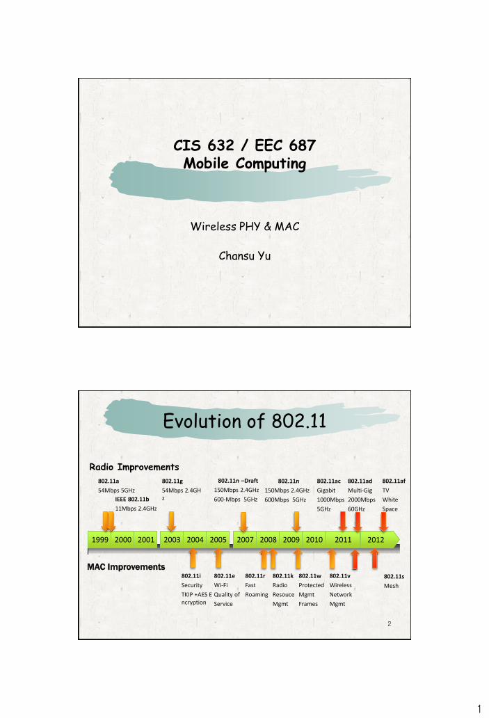
Evolution of 802.11
2
Radio Improvements
IEEE 802.11b
11Mbps 2.4GHz
802.11n
150Mbps 2.4GHz
600Mbps 5GHz
802.11ac
Gigabit
1000Mbps
5GHz
802.11a
54Mbps 5GHz
802.11i
Security
TKIP +AES Encryption
802.11g
54Mbps 2.4GHz
802.11ad
Multi-Gig
2000Mbps
60GHz
20121999 2000 2001 2003 2004 2005 2007 2008 2009 2010 2011
MAC Improvements802.11e
Wi-Fi
Quality of
Service
802.11k
Radio
Resouce
Mgmt
802.11v
Wireless
Network
Mgmt
802.11r
Fast
Roaming
802.11w
Protected
Mgmt
Frames
802.11af
TV
White
Space
802.11n –Draft
150Mbps 2.4GHz
600-Mbps 5GHz
802.11s
Mesh
2
3
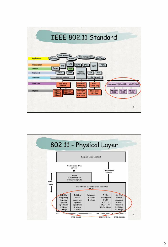
IEEE 802.11 Standard
4
802.11 - Physical Layer
3
5
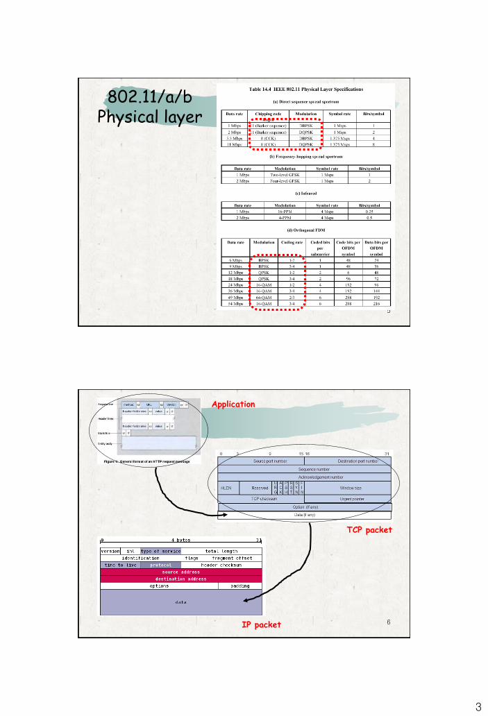
802.11/a/bPhysical layer
6
Application
TCP packet
IP packet
4
7
IP packet
Frame
controlDuration Addr1 Addr2 Payload
2 2 6 6 0-2312
Addr3
6
CRC
4Seq.
control
2
Addr4
6
synchronization SFD signal service HEC Payload (MPDU)
PLCP preamble PLCP header
128 16 8 8 16 variable
length
16
802.11 MAC packet
802.11 PHY packet
8
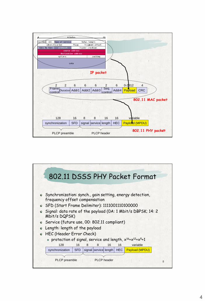
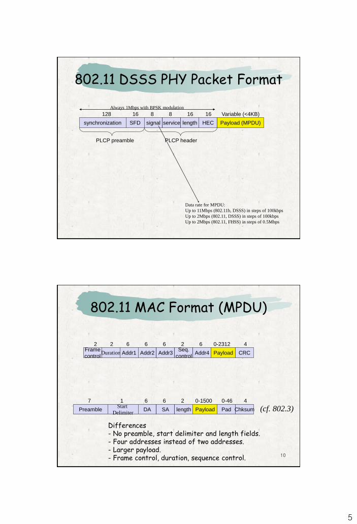
802.11 DSSS PHY Packet Format
synchronization SFD signal service HEC Payload (MPDU)
PLCP preamble PLCP header
128 16 8 8 16 variable
length
16
Synchronization: synch., gain setting, energy detection, frequency offset compensation
SFD (Start Frame Delimiter): 1111001110100000
Signal: data rate of the payload (0A: 1 Mbit/s DBPSK; 14: 2 Mbit/s DQPSK)
Service (future use, 00: 802.11 compliant)
Length: length of the payload
HEC (Header Error Check)
protection of signal, service and length, x16+x12+x5+1
5
802.11 DSSS PHY Packet Format
synchronization SFD signal service HEC Payload (MPDU)
PLCP preamble PLCP header
128 16 8 8 16
length
16
Always 1Mbps with BPSK modulation
Data rate for MPDU:
Up to 11Mbps (802.11b, DSSS) in steps of 100kbps
Up to 2Mbps (802.11, DSSS) in steps of 100kbps
Up to 2Mbps (802.11, FHSS) in steps of 0.5Mbps
Variable (<4KB)
10
802.11 MAC Format (MPDU)
PreambleStart
DelimiterDA SA PadPayload
7 1 6 6 0-1500
length
2
(cf. 802.3)Chksum
0-46 4
Frame
controlDuration Addr1 Addr2 Payload
2 2 6 6 0-2312
Addr3
6
CRC
4Seq.
control
2
Addr4
6
Differences- No preamble, start delimiter and length fields.- Four addresses instead of two addresses.- Larger payload.- Frame control, duration, sequence control.
6
Frame
controlDuration Addr1 Addr2 Payload
2 2 6 6 0-2312
Addr3
6
CRC
4Seq.
control
2
Addr4
6
A B C
RTS
CTSCTS
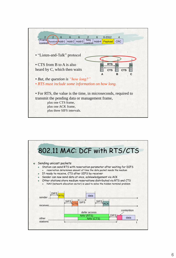
• “Listen-and-Talk” protocol
• CTS from B to A is also
heard by C, which then waits
• But, the question is “how long?”
• RTS must include some information on how long.
• For RTS, the value is the time, in microseconds, required to
transmit the pending data or management frame, plus one CTS frame,
plus one ACK frame,
plus three SIFS intervals.
802.11 MAC: DCF with RTS/CTS
Sending unicast packets Station can send RTS with reservation parameter after waiting for DIFS
reservation determines amount of time the data packet needs the medium
If ready to receive, CTS after SIFS by receiver Sender can now send data at once, acknowledgement via ACK Other stations store medium reservations distributed via RTS and CTS
NAV (network allocation vector) is used to solve the hidden terminal problem
t
SIFS
DIFS
data
ACK
other
stations
receiver
senderdata
DIFS
contention
RTS
CTSSIFS SIFS
defer access
NAV (RTS)NAV (CTS)
7
13
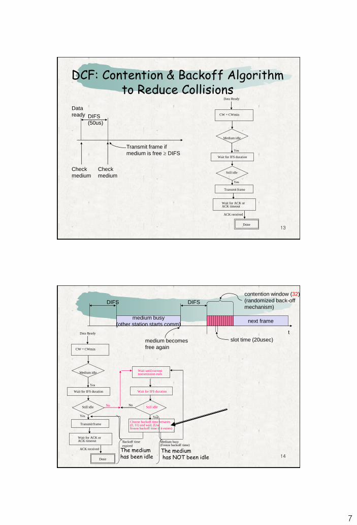
DCF: Contention & Backoff Algorithm to Reduce Collisions
CW = CWmin
Medium idle
Wait for IFS duration
Still idle
Transmit frame
Yes
Yes
Data Ready
Wait for ACK or ACK timeout
ACK received
Done
DIFS
(50us)
Transmit frame if
medium is free DIFS
Check
medium
Check
medium
Data
ready
14
CW = CWmin
Medium idle
Wait for IFS duration
Still idle
Transmit frame
Yes
Wait for ACK or ACK timeout
ACK received
Yes
Done
Data Ready t
medium busy
(other station starts comm)
DIFSDIFS
next frame
contention window (32)
(randomized back-off
mechanism)
slot time (20usec)medium becomes
free again
Wait until current transmission ends
Still idle No No
Wait for IFS duration
Yes
Choose backoff time between (0, 31) and wait. (Use frozen backoff time if it exists)
Backoff time
expired
Medium busy(Freeze backoff time)
The mediumhas been idle
The mediumhas NOT been idle
8
15
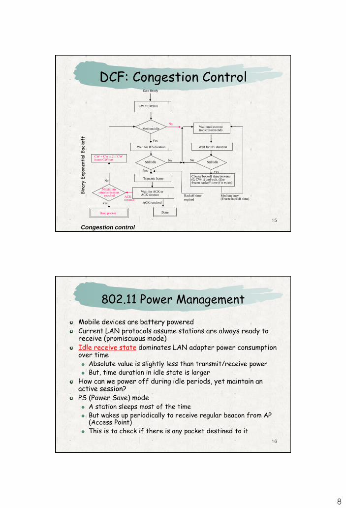
CW = CWmin
Medium idle
Wait for IFS duration
Still idle
Transmit frame
Yes
Wait until current transmission ends
Still idle No
Yes
No
Choose backoff time between (0, CW-1) and wait. (Use frozen backoff time if it exists)
Wait for ACK or ACK timeout
ACK received
No
Yes
Wait for IFS duration
Done
Data Ready
Backoff time
expired
Medium busy(Freeze backoff time)
Yes
Maximumretransmissions
reached
CW = CW 2 if CW is not CWmax
No
Drop packet
ACK timeout
Congestion control
DCF: Congestion ControlB
inar
y E
xpo
nent
ial
Bac
koff
16
802.11 Power Management
Mobile devices are battery poweredCurrent LAN protocols assume stations are always ready to receive (promiscuous mode)Idle receive state dominates LAN adapter power consumption over time Absolute value is slightly less than transmit/receive power But, time duration in idle state is larger
How can we power off during idle periods, yet maintain an active session?PS (Power Save) mode A station sleeps most of the time But wakes up periodically to receive regular beacon from AP
(Access Point) This is to check if there is any packet destined to it
9
17
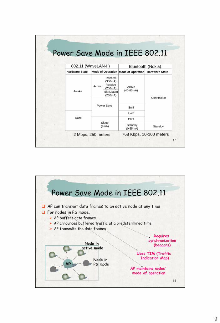
Power Save Mode in IEEE 802.11
768 Kbps, 10-100 meters2 Mbps, 250 meters
802.11 (WaveLAN-II) Bluetooth (Nokia)Hardware State Mode of Operation Mode of Operation Hardware State
Transmit
(300mA)
Receive
(250mA)
Idle(Listen)
(230mA)
Active
Awake
Power Save
Sleep
(9mA)
Doze
Active
(40-60mA)
Sniff
Hold
Park
Connection
StandbyStandby
(0.55mA)
18
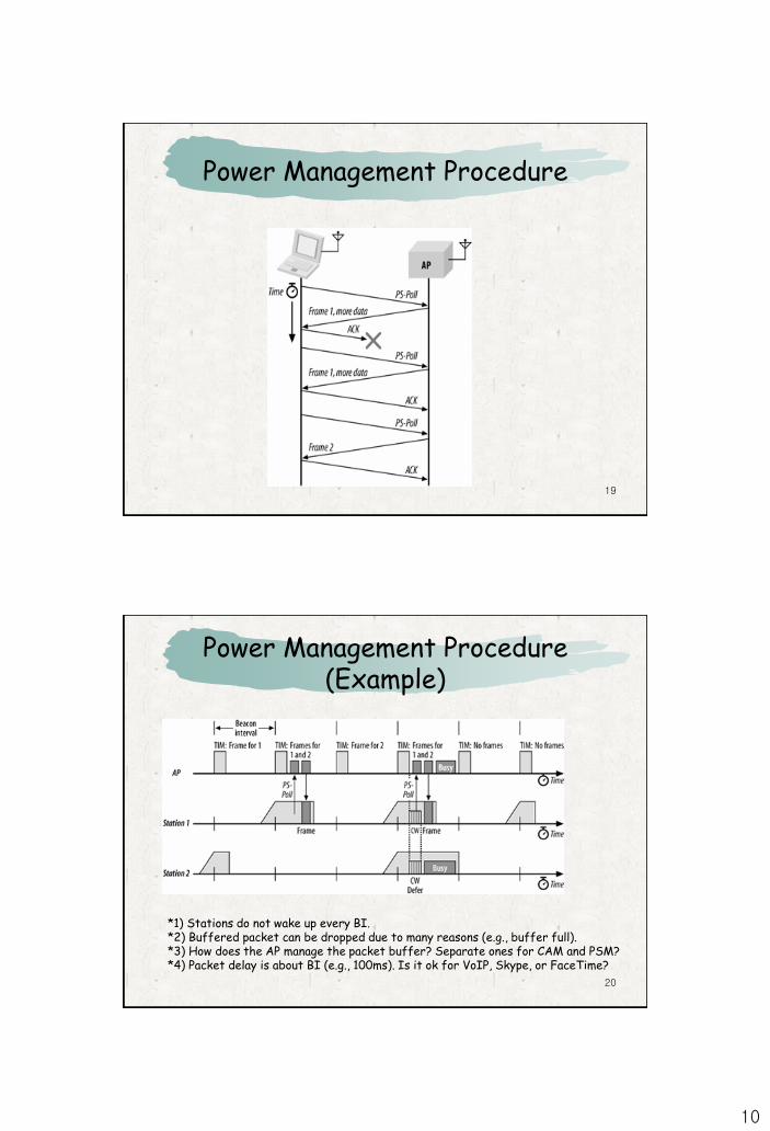
Power Save Mode in IEEE 802.11
AP can transmit data frames to an active node at any time
For nodes in PS mode, AP buffers data frames
AP announces buffered traffic at a predetermined time
AP transmits the data frames
AP
Node in active mode
Node in PS mode
Requires synchronization
(beacons)
Uses TIM (Traffic Indication Map)
AP maintains nodes’ mode of operation
10
19
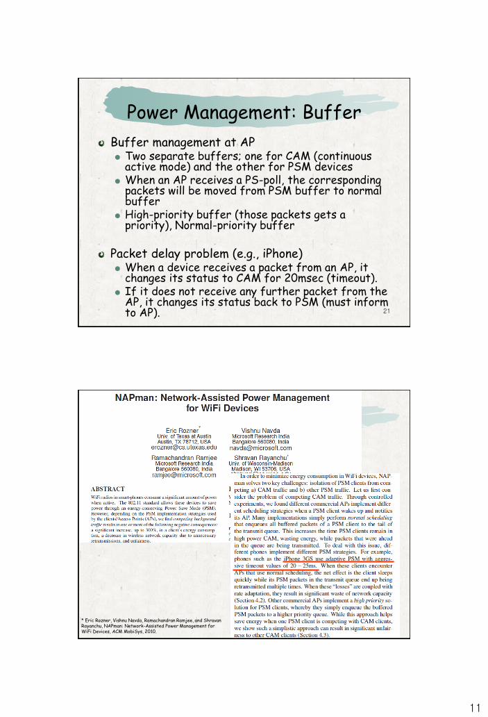
Power Management Procedure
20
Power Management Procedure (Example)
*1) Stations do not wake up every BI.*2) Buffered packet can be dropped due to many reasons (e.g., buffer full).*3) How does the AP manage the packet buffer? Separate ones for CAM and PSM?*4) Packet delay is about BI (e.g., 100ms). Is it ok for VoIP, Skype, or FaceTime?
11
21
Power Management: Buffer
Buffer management at AP Two separate buffers; one for CAM (continuous
active mode) and the other for PSM devices When an AP receives a PS-poll, the corresponding
packets will be moved from PSM buffer to normal buffer
High-priority buffer (those packets gets a priority), Normal-priority buffer
Packet delay problem (e.g., iPhone) When a device receives a packet from an AP, it
changes its status to CAM for 20msec (timeout). If it does not receive any further packet from the
AP, it changes its status back to PSM (must inform to AP).
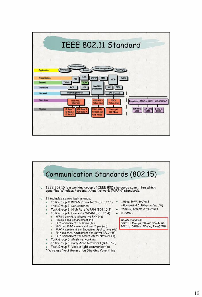
22* Eric Rozner, Vishnu Navda, Ramachandran Ramjee, and Shravan Rayanchu, NAPman: Network-Assisted Power Management for WiFi Devices, ACM MobiSys, 2010.
12
IEEE 802.11 Standard
Communication Standards (802.15)
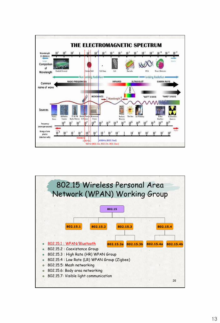
IEEE 802.15 is a working group of IEEE 802 standards committee which specifies Wireless Personal Area Network (WPAN) standards.
It includes seven task groups. Task Group 1: WPAN / Bluetooth (802.15.1) Task Group 2: Coexistence Task Group 3: High Rate WPAN (802.15.3) Task Group 4: Low Rate WPAN (802.15.4)
WPAN Low Rate Alternative PHY (4a) Revision and Enhancement (4b) PHY Amendment for China (4c) PHY and MAC Amendment for Japan (4d) MAC Amendment for Industrial Applications (4e) PHY and MAC Amendment for Active RFID (4f) PHY Amendment for Smart Utility Network (4g)
Task Group 5: Mesh networking Task Group 6: Body Area Networks (802.15.6) Task Group 7: Visible light communication* Wireless Next Generation Standing Committee
1Mbps, 1mW, 8mJ/MB
(Bluetooth 4.0: 1Mbps, a few uW)
55Mbps, 200uW, 0.03mJ/MB
0.25Mbps
WLAN standards802.11b: 11Mbps, 50mW, 36mJ/MB802.11g: 54Mbps, 50mW, 7.4mJ/MB
13
900MHz2.4GHz
5GHz (802.11a, 802.11n, 802.11ac)
60GHz (802.11ad)
2626
802.15 Wireless Personal Area Network (WPAN) Working Group
802.15
802.15.1 802.15.2
802.15.4b802.15.3a 802.15.3b
802.15.4802.15.3
802.15.1 : WPAN/Bluetooth
802.15.2 : Coexistence Group
802.15.3 : High Rate (HR) WPAN Group
802.15.4 : Low Rate (LR) WPAN Group (Zigbee)
802.15.5: Mesh networking
802.15.6: Body area networking
802.15.7: Visible light communication
802.15.4a
14
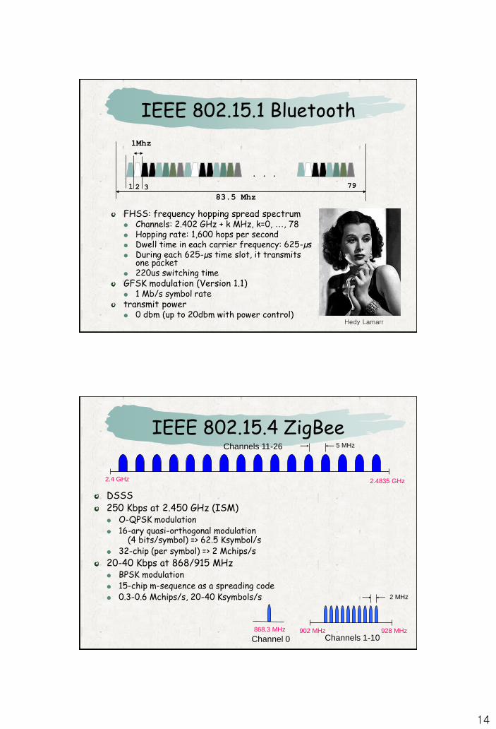
IEEE 802.15.1 Bluetooth
FHSS: frequency hopping spread spectrum Channels: 2.402 GHz + k MHz, k=0, …, 78 Hopping rate: 1,600 hops per second Dwell time in each carrier frequency: 625-µs During each 625-µs time slot, it transmits
one packet 220us switching timeGFSK modulation (Version 1.1) 1 Mb/s symbol ratetransmit power 0 dbm (up to 20dbm with power control)
. . .
1Mhz
1 2 3 79
83.5 Mhz
Hedy Lamarr
IEEE 802.15.4 ZigBee
DSSS250 Kbps at 2.450 GHz (ISM) O-QPSK modulation 16-ary quasi-orthogonal modulation
(4 bits/symbol) => 62.5 Ksymbol/s 32-chip (per symbol) => 2 Mchips/s
20-40 Kbps at 868/915 MHz BPSK modulation 15-chip m-sequence as a spreading code 0.3-0.6 Mchips/s, 20-40 Ksymbols/s
868.3 MHz
Channel 0 Channels 1-10928 MHz902 MHz
2 MHz
2.4 GHz
Channels 11-26
2.4835 GHz
5 MHz
15
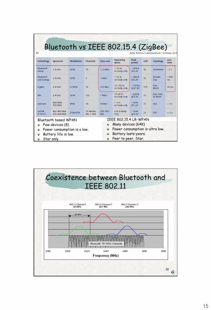
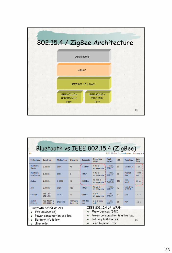
Bluetooth vs IEEE 802.15.4 (ZigBee)
Bluetooth based WPANFew devices (8)Power consumption is a low.Battery life is low.Star only.
IEEE 802.15.4 LR-WPANMany devices (64K)Power consumption is ultra low.Battery lasts years.Peer to peer, Star.
3030
Coexistence between Bluetooth and IEEE 802.11
16
31
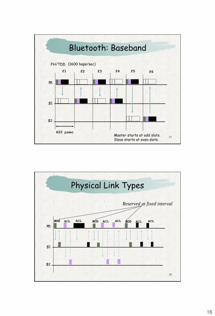
Bluetooth: Baseband
m
s1
s2
625 sec
f1 f2 f3 f4
(1600 hops/sec)
f5 f6
FH/TDD
Master starts at odd slots.Slave starts at even slots.
32
Physical Link Types
m
s1
s2
SCO SCO SCOSCO SCO SCOACL ACL ACLACL ACL ACL
Reserved at fixed interval
17
33
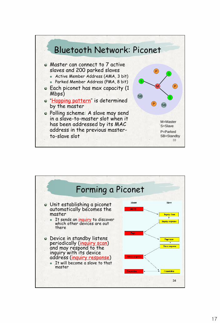
Bluetooth Network: Piconet
M=Master
S=Slave
P=Parked
SB=Standby
M
S
P
SB
S
S
P
P
SB
Master can connect to 7 active slaves and 200 parked slaves Active Member Address (AMA, 3 bit) Parked Member Address (PMA, 8 bit)
Each piconet has max capacity (1 Mbps)“Hopping pattern” is determined by the masterPolling scheme: A slave may send in a slave-to-master slot when it has been addressed by its MAC address in the previous master-to-slave slot
3434
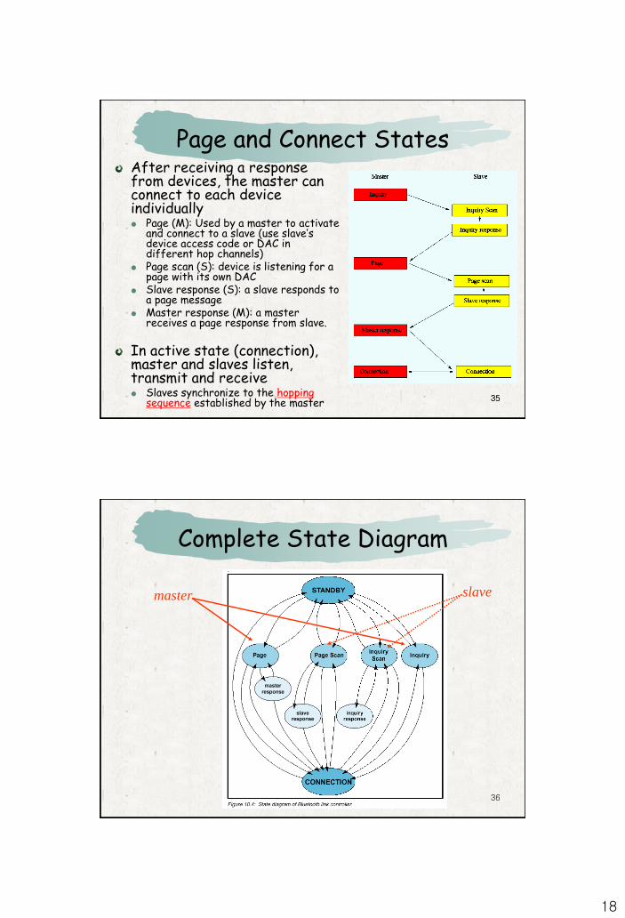
Forming a Piconet
Unit establishing a piconet automatically becomes the master It sends an inquiry to discover
which other devices are out there
Device in standby listens periodically (inquiry scan) and may respond to the inquiry with its device address (inquiry response) It will become a slave to that
master
18
3535
Page and Connect StatesAfter receiving a response from devices, the master can connect to each device individually Page (M): Used by a master to activate
and connect to a slave (use slave’s device access code or DAC in different hop channels)
Page scan (S): device is listening for a page with its own DAC
Slave response (S): a slave responds to a page message
Master response (M): a master receives a page response from slave.
In active state (connection), master and slaves listen, transmit and receive Slaves synchronize to the hopping
sequence established by the master
36
Complete State Diagram
slavemaster
19
3737
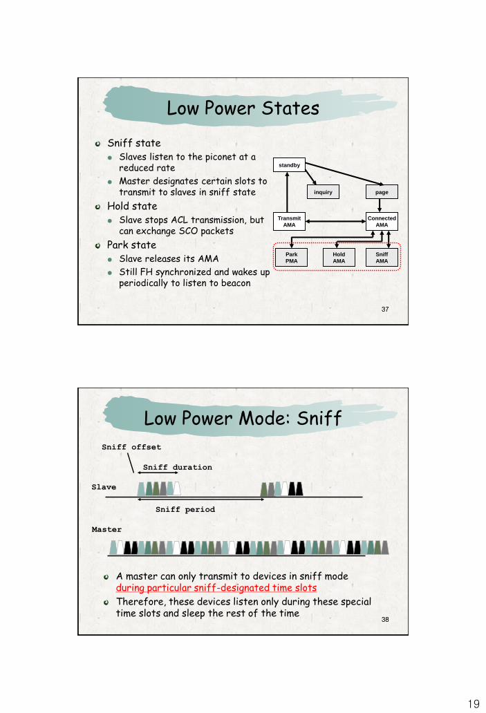
Low Power States
Sniff state Slaves listen to the piconet at a
reduced rate
Master designates certain slots to transmit to slaves in sniff state
Hold state Slave stops ACL transmission, but
can exchange SCO packets
Park state Slave releases its AMA
Still FH synchronized and wakes up periodically to listen to beacon
standby
inquiry page
Transmit
AMA
Connected
AMA
Park
PMA
Hold
AMA
Sniff
AMA
3838
Low Power Mode: Sniff
Master
Slave
Sniff period
Sniff offset
Sniff duration
A master can only transmit to devices in sniff mode during particular sniff-designated time slots
Therefore, these devices listen only during these special time slots and sleep the rest of the time
20
3939
Low Power Mode: Hold
Slave
Hold duration
Hold offset
Master
A slave in hold mode, alternatively, does not receive any asynchronous packets and listens only to determine if it should become active again (but still participate in SCO exchanges)
4040
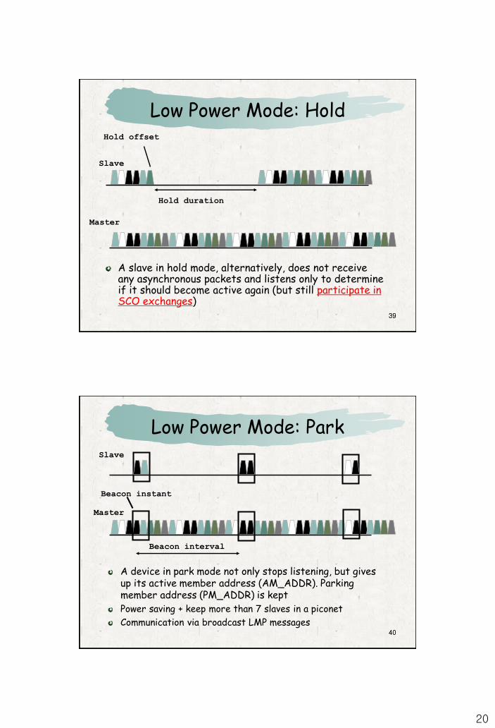
Low Power Mode: Park
Master
Slave
Beacon interval
Beacon instant
A device in park mode not only stops listening, but gives up its active member address (AM_ADDR). Parking member address (PM_ADDR) is kept
Power saving + keep more than 7 slaves in a piconet
Communication via broadcast LMP messages
21
4141
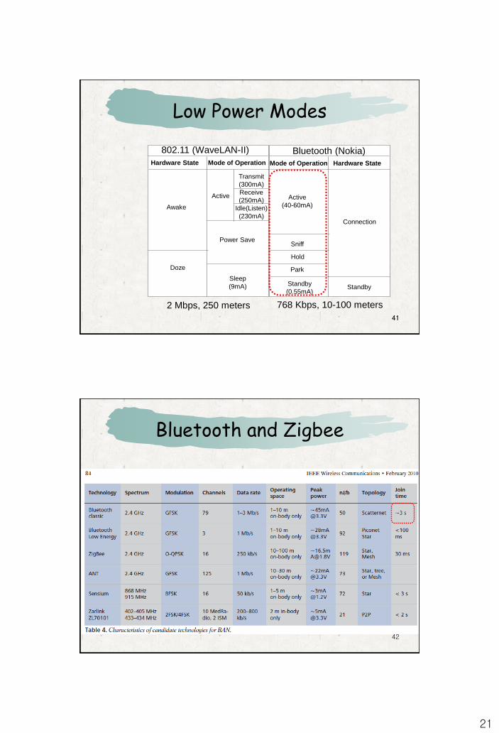
Low Power Modes
768 Kbps, 10-100 meters2 Mbps, 250 meters
802.11 (WaveLAN-II) Bluetooth (Nokia)Hardware State Mode of Operation Mode of Operation Hardware State
Transmit
(300mA)
Receive
(250mA)
Idle(Listen)
(230mA)
Active
Awake
Power Save
Sleep
(9mA)
Doze
Active
(40-60mA)
Sniff
Hold
Park
Connection
StandbyStandby
(0.55mA)
42
Bluetooth and Zigbee
22
43
Hop Selection (Volume 2, Part B, Section 2.6 of Bluetooth 2.0 Spec.)
Which hops to use for data communications? A basic channel hopping sequence An adapted channel hopping sequence
When devices is in standby mode, which hops does the master use for discovering the devices(page, inquiry)? A page hopping sequence A page response hopping sequence An inquiry hopping sequence An inquiry response hopping sequence
44
Hop Selection (Volume 2, Part B, Section 2.6 of Bluetooth 2.0 Spec.)
A basic channel hopping sequence which has a very long period length, which does not show repetitive patterns over a short time interval, and which distributes the hop frequencies equally over the 79 MHz during a short time interval.
An adapted channel hopping sequence derived from the basic channel hopping sequence which uses the same channel mechanism and may use fewer than 79 frequencies. The adapted channel hopping sequence is only used in place of the basic channel hopping sequence. All other hopping sequences are not affected by hop sequence adaptation.
23
45
Hop Selection (Volume 2, Part B, Section 2.6 of Bluetooth 2.0 Spec.)A page hopping sequence with 32 wake-up frequencies distributed equally over the 79 MHz, with a period length of 32;A page response hopping sequence covering 32 response frequencies that are in a one-to-one correspondence to the current page hopping sequence. The master and slave use different rules to obtain the same sequence;An inquiry hopping sequence with 32 wake-up frequencies distributed equally over the 79 MHz, with a period length of 32;An inquiry response hopping sequence covering 32 response frequencies that are in a one-to-one correspondence to the current inquiry hopping sequence.
46
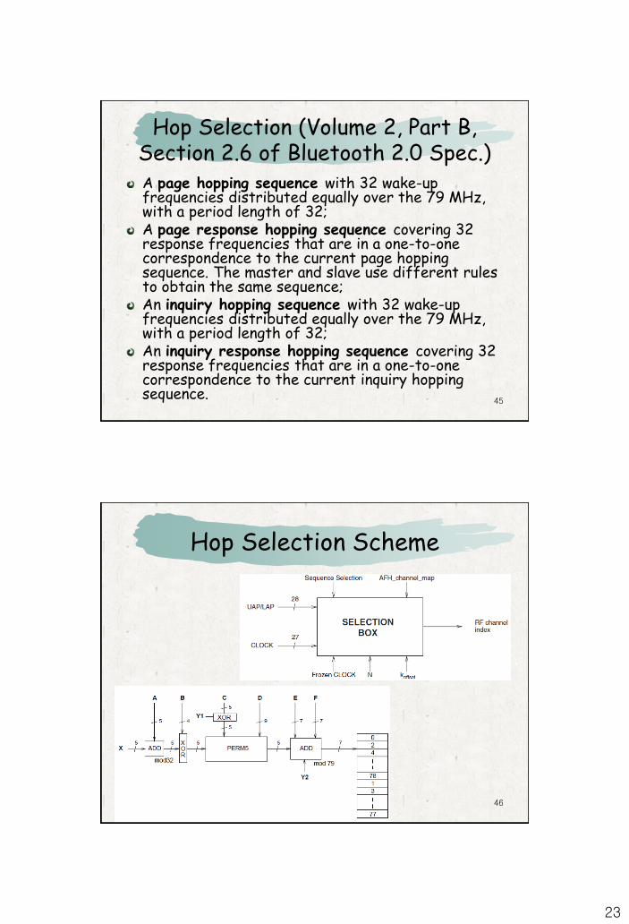
Hop Selection Scheme
24
47
Quiz: Connection Latency
A device becomes a master by initiating a connection (if he knows the address of the receiver) Send 16 identical page messages on 16 different hop
frequencies and then remaining 16 frequencies (send on 2 channels in one slot and listen in the next slot => takes 16 slots for trying all 16 channels)
A device in unconnected listens for paging messages Tune to 32 wakeup carriers (chosen based on device’s identity)
every 2048 slots (1.28 sec) for 18 slots (11.25 msec) Gets the DeviceAccessCode, goes into “connected” state and
he becomes a “slave” The slave then synchronize to the master's clock and to the
correct frequency hopping pattern
What is the maximum delay for connection ?
* Volume 2, Part B, Sections 2, 8.3 of Bluetooth 2.0 Spec
4848
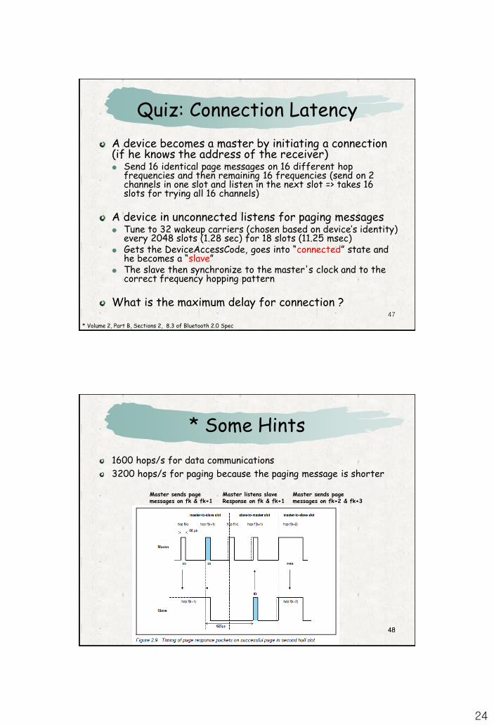
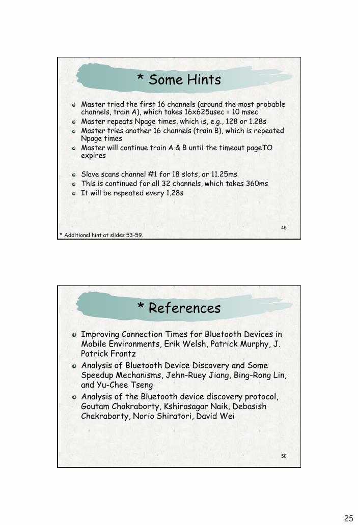
* Some Hints
1600 hops/s for data communications
3200 hops/s for paging because the paging message is shorter
Master sends page messages on fk & fk+1
Master listens slave Response on fk & fk+1
Master sends page messages on fk+2 & fk+3
25
4949
* Some Hints
Master tried the first 16 channels (around the most probable channels, train A), which takes 16x625usec = 10 msecMaster repeats Npage times, which is, e.g., 128 or 1.28sMaster tries another 16 channels (train B), which is repeated Npage timesMaster will continue train A & B until the timeout pageTO expires
Slave scans channel #1 for 18 slots, or 11.25msThis is continued for all 32 channels, which takes 360msIt will be repeated every 1.28s
* Additional hint at slides 53-59.
50
* References
Improving Connection Times for Bluetooth Devices in Mobile Environments, Erik Welsh, Patrick Murphy, J. Patrick Frantz
Analysis of Bluetooth Device Discovery and Some Speedup Mechanisms, Jehn-Ruey Jiang, Bing-Rong Lin, and Yu-Chee Tseng
Analysis of the Bluetooth device discovery protocol, Goutam Chakraborty, Kshirasagar Naik, Debasish Chakraborty, Norio Shiratori, David Wei
50
26
51
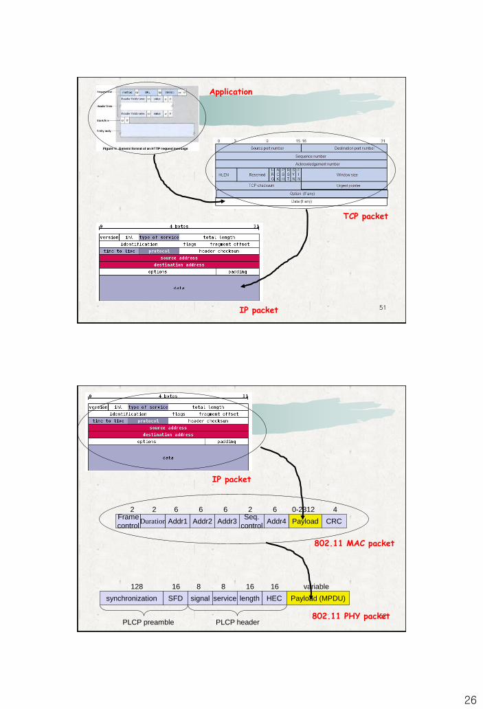
Application
TCP packet
IP packet
52
IP packet
Frame
controlDuration Addr1 Addr2 Payload
2 2 6 6 0-2312
Addr3
6
CRC
4Seq.
control
2
Addr4
6
synchronization SFD signal service HEC Payload (MPDU)
PLCP preamble PLCP header
128 16 8 8 16 variable
length
16
802.11 MAC packet
802.11 PHY packet
27
53
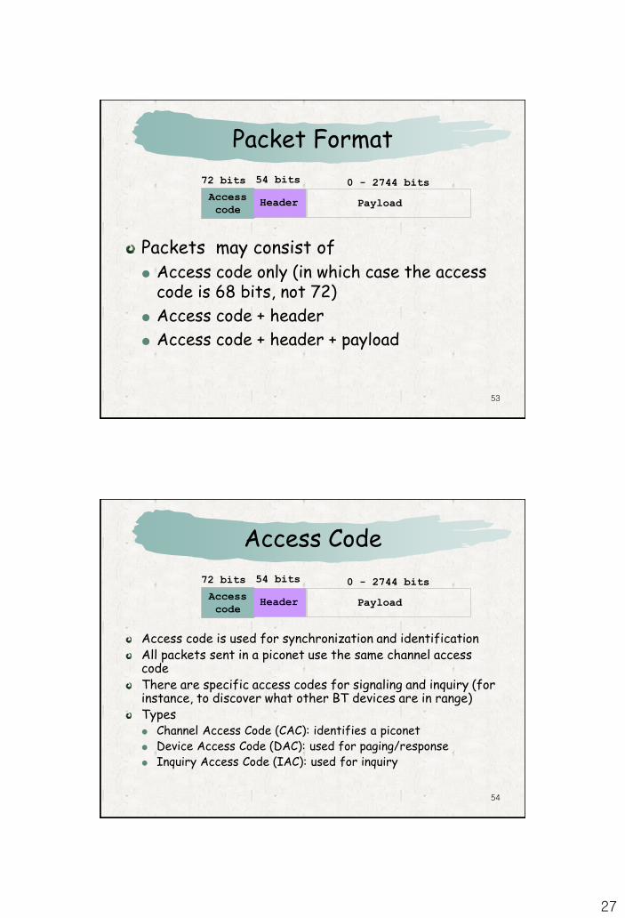
Packet Format
Packets may consist of Access code only (in which case the access
code is 68 bits, not 72)
Access code + header
Access code + header + payload
72 bits 54 bits 0 - 2744 bits
Access
codeHeader Payload
54
Access Code
Access code is used for synchronization and identificationAll packets sent in a piconet use the same channel access codeThere are specific access codes for signaling and inquiry (for instance, to discover what other BT devices are in range)Types Channel Access Code (CAC): identifies a piconet Device Access Code (DAC): used for paging/response Inquiry Access Code (IAC): used for inquiry
72 bits 54 bits 0 - 2744 bits
Access
codeHeader Payload
28
55
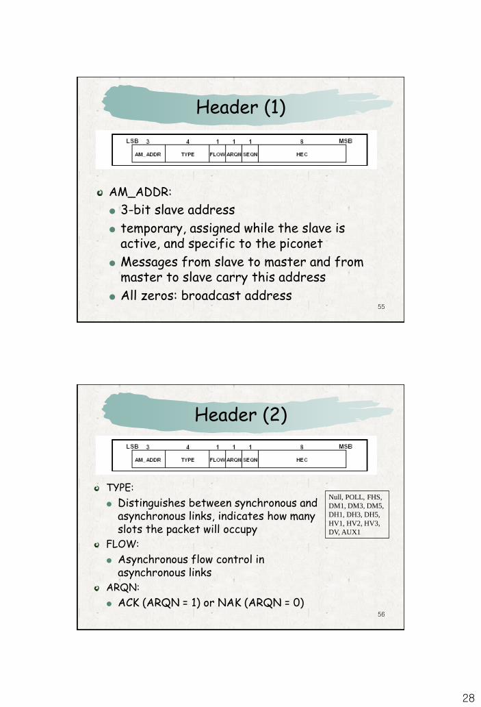
Header (1)
AM_ADDR:
3-bit slave address
temporary, assigned while the slave is active, and specific to the piconet
Messages from slave to master and from master to slave carry this address
All zeros: broadcast address
56
Header (2)
TYPE:
Distinguishes between synchronous and asynchronous links, indicates how many slots the packet will occupy
FLOW:
Asynchronous flow control in asynchronous links
ARQN:
ACK (ARQN = 1) or NAK (ARQN = 0)
Null, POLL, FHS,
DM1, DM3, DM5,
DH1, DH3, DH5,
HV1, HV2, HV3,
DV, AUX1
29
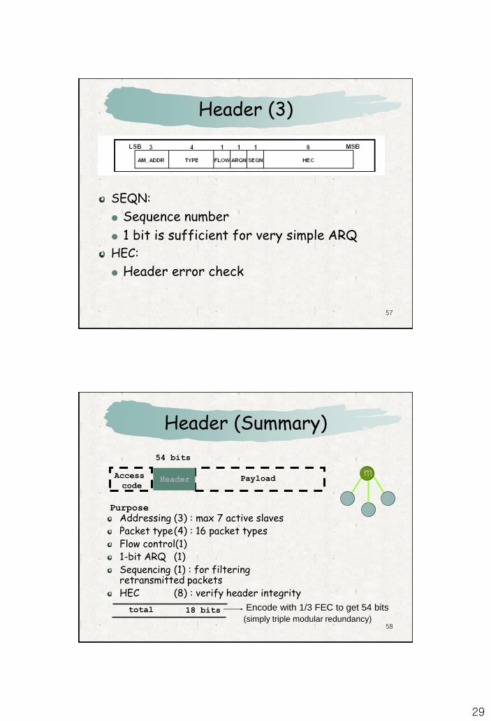
57
Header (3)
SEQN:
Sequence number
1 bit is sufficient for very simple ARQHEC:
Header error check
58
Header (Summary)
Addressing (3) : max 7 active slavesPacket type(4) : 16 packet typesFlow control(1)1-bit ARQ (1)Sequencing (1) : for filtering retransmitted packetsHEC (8) : verify header integrity
Access
codeHeader Payload
54 bits
Purpose
Encode with 1/3 FEC to get 54 bits
(simply triple modular redundancy)18 bitstotal
ss
m
s
30
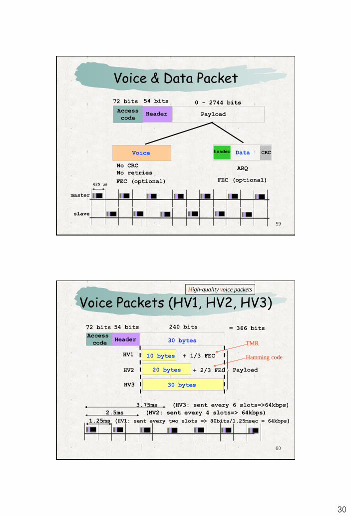
59
Voice & Data Packet
72 bits 54 bits 0 - 2744 bits
Access
codeHeader Payload
DataVoice CRC
No CRC
No retries
625 µs
master
slave
ARQ
FEC (optional) FEC (optional)
60
Voice Packets (HV1, HV2, HV3)
Access
codeHeader
Payload
72 bits 54 bits 240 bits
30 bytes
= 366 bits
10 bytes
+ 2/3 FEC
+ 1/3 FEC
20 bytes
30 bytesHV3
HV2
HV1
3.75ms (HV3: sent every 6 slots=>64kbps)
2.5ms (HV2: sent every 4 slots=> 64kbps)
1.25ms (HV1: sent every two slots => 80bits/1.25msec = 64kbps)
TMR
Hamming code
High-quality voice packets
31
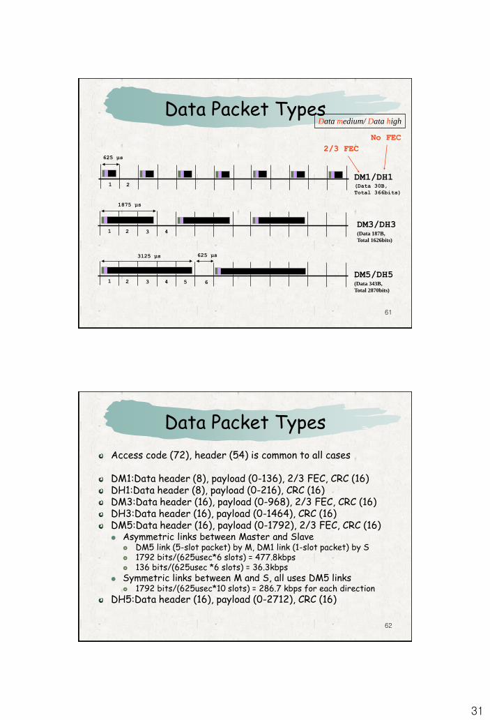
61
Data Packet Types
625 µs
1 2
1875 µs
1 2 3 4
3125 µs 625 µs
1 2 3 4 5 6
DM1/DH1(Data 30B,
Total 366bits)
DM3/DH3(Data 187B,
Total 1626bits)
DM5/DH5(Data 343B,
Total 2870bits)
2/3 FEC
No FEC
Data medium/ Data high
62
Data Packet Types
Access code (72), header (54) is common to all cases
DM1:Data header (8), payload (0-136), 2/3 FEC, CRC (16)DH1:Data header (8), payload (0-216), CRC (16)DM3:Data header (16), payload (0-968), 2/3 FEC, CRC (16)DH3:Data header (16), payload (0-1464), CRC (16)DM5:Data header (16), payload (0-1792), 2/3 FEC, CRC (16) Asymmetric links between Master and Slave
DM5 link (5-slot packet) by M, DM1 link (1-slot packet) by S 1792 bits/(625usec*6 slots) = 477.8kbps 136 bits/(625usec *6 slots) = 36.3kbps
Symmetric links between M and S, all uses DM5 links 1792 bits/(625usec*10 slots) = 286.7 kbps for each direction
DH5:Data header (16), payload (0-2712), CRC (16)
32
63
Quiz: Packet Types
1. Bluetooth supports asynchronous and asymmetric data traffic up to 723.2/57.6 Kbps. Which data packet types are used for that data rate?
2. Which combination of data packet types produces the maximum throughput?
3. Bluetooth supports three types of voice packets, HV1, HV2 and HV3. Do they differ in packet rate (number of packets per second)? Do they differ in resulting data rate? (Yes, No)
4. A group of piconets is called a scatternet. Can a slave of a piconet belong to another piconet as a slave or a master? Can a master of a piconet belong to another piconet as a slave or a master? (Yes, No)
6464
IEEE 802.15.4
IEEE 802.15.4 task group began to develop a standard for low-rate WPAN (LR-WPAN).
The goal of this group was to provide a standard with ultra-low complexity, cost, and power for low-data-rate wireless connectivity among inexpensive devices.
The Zigbee Alliance is an association of companies involved with building higher-layer standards based on IEEE 802.15.4. This includes network, security, and application protocols.
33
65
IEEE 802.15.4 MAC
Applications
IEEE 802.15.4
2400 MHz
PHY
IEEE 802.15.4
868/915 MHz
PHY
802.15.4 / ZigBee Architecture
ZigBee
66
Bluetooth vs IEEE 802.15.4 (ZigBee)
Bluetooth based WPANFew devices (8)Power consumption is a low.Battery life is low.Star only.
IEEE 802.15.4 LR-WPANMany devices (64K)Power consumption is ultra low.Battery lasts years.Peer to peer, Star.
34
67
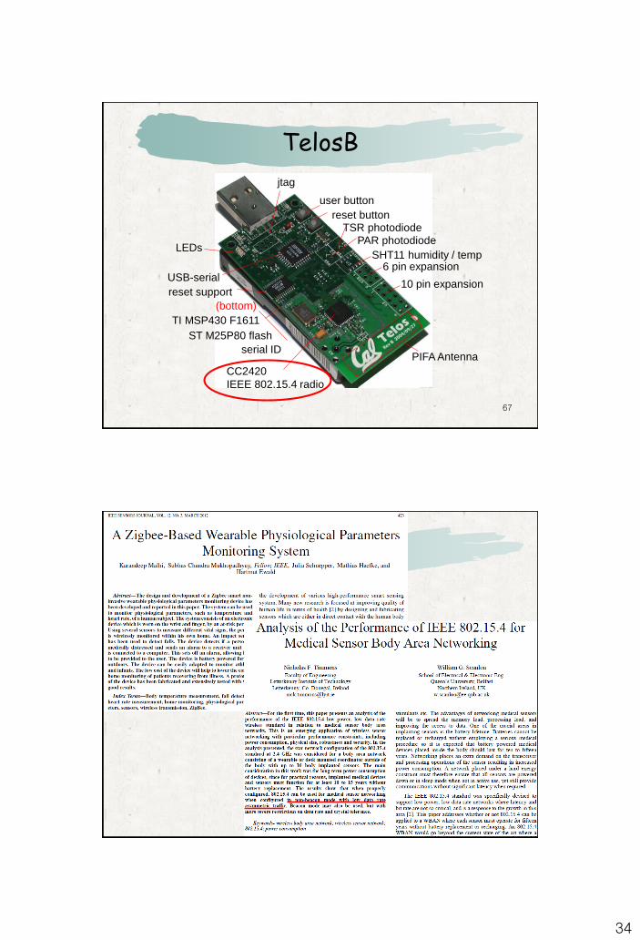
TelosB
CC2420
IEEE 802.15.4 radio
PIFA Antenna
USB-serial10 pin expansion
6 pin expansionSHT11 humidity / temp
TI MSP430 F1611
reset button
user button
TSR photodiode
PAR photodiodeLEDs
(bottom)
ST M25P80 flash
reset support
jtag
serial ID
68