cis barb insertion tool instructions hunobtainiumsupply.com/downloads/instructions/cis barb...
TRANSCRIPT

K-Jetronic(CIS) Barb Insertion Tool
Instructions
Rev. HEffective: 14-JUN-2015
Unobtainium Supply Co.523 Longley Rd
Groton, MA 01450978.448.2110
www.UnobtainiumSupply.com

ContentsK-Jetronic (CIS) BARB INSERTION TOOL INSTRUCTIONS ...................................... 3
USING THE BARB INSERTION TOOL ............................................................................ 38mm LINE BARB INSERTION .................................................................................. 13WOODEN BLOCK BARB INSERTION TOOL: ....................................................... 15

K-Jetronic (CIS) BARB INSERTION TOOLINSTRUCTIONS
USING THE BARB INSERTION TOOLThese instructions apply to both the V1 maple barb insertion tool, and also theV2 plastic barb insertion tool.
It is suggested that you read this FerrariChat topic for the latest CIS fuel linerestoration tips:
Unobtainium Supplies: K-Jetronic (CIS) Plastic Fuel Line/HoseRestoration Kit
http://www.ferrarichat.com/forum/showthread.php?t=186689
In addition to the tool, you will need:- K-Jetronic (CIS) Plastic (or SS braid covered) Fuel Line/Hose Restoration
Kit- Heat Gun (think industrial strength hair dryer).- Vise- End Cutting pliers- Tubing Flaring tool or wooden blocks(see below).
NOTE:The K-Jetronic (CIS) Plastic Fuel Line/Hose Restoration Kit (soldseparately) contains sufficient lengths of the correct 5mm, 6mm,& 8mmblack polyamide(aka: Nylon™) Cohline™, imported from Germany, torestore a Ferrari CIS system. There is enough extra line of each size toallow for several mistakes while learning how to insert the metal barbsinto the line.
The following steps will guide you in restoring your fuel lines. They begin withremoving the old fuel line and guide you thru using the tool to install the barbsinto the new line:
1. Remove the old line.Make sure there is no fuel remaining in the old line. Blowing it out withcompressed air is the best way to ensure this. This is important becausethe old fuel can ignite producing a mini-explosion & turning the tube intoa mini flame-thrower!!!!
Heat the old line with a hot air gun until it is very soft and can be pulled offof the barb by hand. Alternatively, a soldering iron can be used to melt agroove the length of the barb allowing the line to be pulled off.
Either of the above methods avoid the risk of scratching the barb whenscoring the tubing as described in the BOSCH literature. It makes removalmuch easier and is a LOT FASTER than the scoring method!
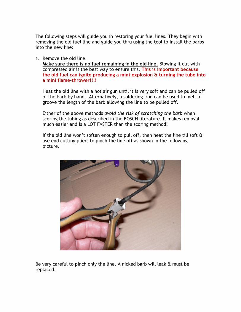
If the old line won’t soften enough to pull off, then heat the line till soft &use end cutting pliers to pinch the line off as shown in the followingpicture.
Be very careful to pinch only the line. A nicked barb will leak & must bereplaced.
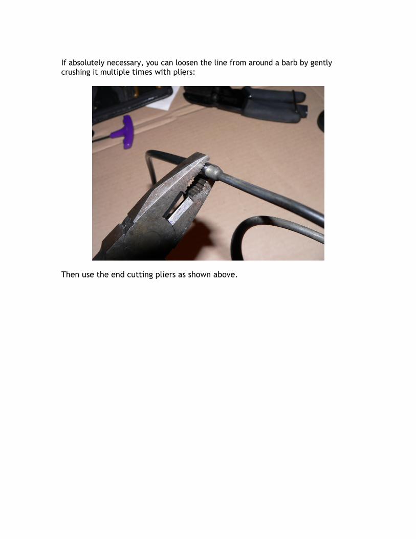
If absolutely necessary, you can loosen the line from around a barb by gentlycrushing it multiple times with pliers:
Then use the end cutting pliers as shown above.

2. Let the barb cool to room temperature before inserting it into the new line.
3. Separate the bottom section of the tool from the top. The pieces are shownin this picture:

The following illustration shows the insertion tool's two bottom halves. Thegroove’s lower smaller width section clamps the line and the wider uppersection provides room for the barb to expand the line. The tool can handleboth the 6mm & 5mm lines just by switching sides. The top section willproperly align the barb with either of the bottom grooves.
4. Insert the line’s end into one side of the bottom section. The line shouldextend slightly above upper edge. Next slide the other half over the pinsand clamp the tool’s bottom section in a vice. The round alignment pins willkeep the tool from sliding down thru the vice jaws.
The vice jaws both clamp the line in the bottom half, and also provide theouter edges of rectangular guides for the top section’s square alignmentkeys. The square keys ensure the barb is kept vertical & goes straight intothe tube.

5. Loosen the top section thumb screw loose enough so that gap between thehalves is wide enough to insert the tubing barb or banjo fitting.
6. Insert the tubing barb (or banjo fitting) between the halves of the topsection.
7. The two top section halves can be left as a sliding fit on the line and barb soit's easy to work with. While the picture shows the top section separated, Inpractice just leave the top section thumb screw loose enough so that the topwill just slide open wide enough to insert the tubing barb or banjo fitting inthe gap between the top pieces.
8. Squeeze the two halves of the top section together, clamping the barb orbanjo between them. Then slip the alignment pins into the square groovesalong the bottom section. The vice jaws holding the bottom half will also holdthe top section together by the square alignment pins.

9. Press the top section downward, inserting the barb into the fuel line:
The preceding picture is a side view just before insertion. The squarealignment grooves in the bottom section along with the vice jaws guide the topsections alignment pins to ensure the barb is exactly aligned with the fuel line.
Note that in this picture the tubing is slightly off-center in the clearance holerelative to the barb’s end.

This is a side view just after beginning insertion using finger pressure. Notethat the barb has brought the tubing back to center!

The following picture shows the tool in its closed position, the barb is fullyinserted.
The barb can usually be fully inserted into 5mm line by pushing down with boththumbs on the tool’s top. The barb can sometimes be fully seated into 6mmtubing by hand, but it often takes a tap or 2 with a plastic mallet on the tool’stop of the to ensure it's fully seated.
Note that in the above picture the set screw isn't fully tight. The setscrewdoesn’t need to be tight as the square alignment pins and vice jaws will holdthe top closed. The screw is just loose enough for the barbed line or banjo toslip in & out between the halves. This can speed up operation considerably!
NOTE:The large banjo on top of the fuel distributor will not fit into the tool’s upperhalf. Use this alternate procedure to install the oversize barb:
1. Clamp the new line in the bottom half as previously described.2. Hold the large banjo place with your fingers with it’s barb pointing
straight down into the line’s opening. Alternatively, use a piece of

wooden dowel, or other cylindrical object thru the banjo’s center holeto hold the banjo.
3. Tap on the banjo’s top with a plastic hammer to drive its barb into thenew line.

8mm LINE BARB INSERTIONThe CIS barb insertion tool is not needed to insert barbs into 8mm line.
Instead, you wrap the area to be clamped with 2 layers of masking tape toprotect the line. Use the clamping part of a tubing flaring tool, or make awooden block tool (see below) clamped into a vise to hold the new 8mm linewhile using a plastic hammer to tap the banjo’s barb into the line.
TIPS for SS Braid covered line: To cut the line: wrap the area to be cut with masking tape, then use a
fine blade saw to cut the line thru the wrapped tape. Use side cutters totrim off any stray protruding wires & trim off any frayed plastic line.Then remove the masking tape.
Barb insertion: Slip the metal sleeve onto the end of the line, then wrap2 layers of masking tape immediately below the sleeve. Insert the lineinto the clamping tool with the sleeve resting on the top edge of thetool. The tool will grip the wrapped tape. It is very important to makesure that the plastic line is firmly clamped, otherwise the barb might bepartially inserted, resulting in a fuel leak. If possible leak test the linewith 90psi compressed air before installing it.
The sleeve does not require crimping. When the barb is inserted, itexpands the plastic line. The expanded plastic line clamps the SS braidfirmly outward against the metal sleeve.
FLARING TOOL:Use the tubing clamp part of a basic flaring tool set, available at most hdwstores. Also often found in the $8.99 tool bin at auto parts stores:

Try the 5/16"(7.94 mm) hole, it should grip fine on either the 8mm plastic or SSbraided line. Only tighten the wing nuts enough to hold the line while insertingthe barb. Once you get the line gripped by the tool, lay the tool between visejaws that grip it & let the wing nuts keep the tool from going thru the vise jawswhile tapping the barb into the fuel line.

WOODEN BLOCK BARB INSERTION TOOL:
This block drawing was posted by echrisconner in one of the Porsche CISthreads. It is just variant of the barb insertion tool's bottom half & works thesame way. In fact, it was the inspiration for the barb insertion tool.
To make one take 2 2” long 1x2 wooden blocks, clamp them together with apiece of cardboard or thin wood about 1/16"-3/32” thick between them, thendrill a 7/32" hole thru the blocks. Next drill the 9/32” hole. Removing thecardboard separator results in the the blocks having slightly less than 1/2 ofthe hole in each block. The partial half-holes will clamp the line firmly, whensnugged together in a vise. Like the barb insertion tool, the larger holesegment is needed to ensure there's room for the barb to expand the line.
Chris’s version uses 4 pins to align the 2 halves. 4 is overkill, 2 is plenty. Infact, If you're just doing a couple of lines, don't bother with the alignment pins.The line itself will hold the 2 blocks in alignment.
If you want alignment pins, clamp the 2 blocks together again, drill thealignment pin holes thru one wooden block & ½ way into the 2nd block. Thedrill size should produce a tight press fit. Press the pins into the block withpartial thru-holes. Then use a drill size that lets the pin slide freely & drill the2 thru-holes in the other block oversize.
Unobtainium Supply Co.523 Longley Rd.
Groton, MA01450